EP2026429A1 - Compact low-voltage safety breaker with completely covered suspension catches - Google Patents
Compact low-voltage safety breaker with completely covered suspension catches Download PDFInfo
- Publication number
- EP2026429A1 EP2026429A1 EP08014360A EP08014360A EP2026429A1 EP 2026429 A1 EP2026429 A1 EP 2026429A1 EP 08014360 A EP08014360 A EP 08014360A EP 08014360 A EP08014360 A EP 08014360A EP 2026429 A1 EP2026429 A1 EP 2026429A1
- Authority
- EP
- European Patent Office
- Prior art keywords
- adapter
- busbar
- protective
- plate element
- busbars
- Prior art date
- Legal status (The legal status is an assumption and is not a legal conclusion. Google has not performed a legal analysis and makes no representation as to the accuracy of the status listed.)
- Withdrawn
Links
Images


Classifications
-
- H—ELECTRICITY
- H02—GENERATION; CONVERSION OR DISTRIBUTION OF ELECTRIC POWER
- H02B—BOARDS, SUBSTATIONS OR SWITCHING ARRANGEMENTS FOR THE SUPPLY OR DISTRIBUTION OF ELECTRIC POWER
- H02B1/00—Frameworks, boards, panels, desks, casings; Details of substations or switching arrangements
- H02B1/20—Bus-bar or other wiring layouts, e.g. in cubicles, in switchyards
- H02B1/21—Bus-bar arrangements for rack-mounted devices with withdrawable units
Definitions
- a low-voltage safety circuit breaker of the type mentioned, referred to as fuse switch disconnectors, is off DE 10 2005 012 364 A1 known.
- the electrically non-conductive protective element is latched to a T-shaped hook clamp.
- the point at which the protective element is to be attached to the hook clamp, selected accordingly, and a resulting in the adapter open space is covered by an additional, insertable into the adapter base masking element.
- the adapter should be turned over by 180 °.
- the T-shaped hook clamps are slidably guided along an inner metal rail.
- safety disconnect switches are known in which a masking the hook clamp protective element is attached to the adapter of the safety disconnector. Again, the protective element for all three phases L1, L2, L3 is identical. However, such devices have no way to adapt the safety disconnector to a different busbar distance.
- Out DE 100 62 634 is a hood-like, attachable to the hook clamp of a circuit breaker protective element known. In order to prevent the falling out of the protective element from the circuit breaker, it is frictionally connected to the hook clamp and held in a strip body of the circuit breaker.
- the object of the invention is to design a compact low-voltage safety isolator, which offers improved protection against accidental touches as well as short circuits during mounting on the busbar system.
- the low-voltage safety isolator should be adaptable to different busbar distances without sacrificing improved protection.
- disconnector is a device that consists of a Adapter, a mounted on the adapter fuse latch and a lid with adjacent fuse links.
- the busbar spacing is normally sized between longitudinal symmetry lines of two adjacent busbars, provided that the width dimension of the busbars is the same.
- the adapter according to the invention is basically intended for two busbar spacings of the size 60 mm and 100 mm.
- the other busbar spacings, such as 40 mm and 80 mm, are not excluded.
- the protective element to be covered by the hook clamp can be connected to the plate element and form a uniform protective body, which is preferably made of a piece of material by injection molding.
- a uniform protective body which is preferably made of a piece of material by injection molding.
- material for the protective body are thermoplastics which are distinguished by improved mechanical properties, such as hardness and impact resistance, and thermal resistance, for example polycarbonates.
- the protective element arranged above the plate element is hood-shaped, so that the hook clamp can be completely covered. This is of great advantage since it virtually eliminates the risk of accidental contact with the hook clamps.
- the protective body can be latched or screwed to the bottom of the adapter.
- a preferred latching connection may comprise resilient webs, tabs, tongues or latching thumbs, which may engage in corresponding grooves, slots, sleeves and gradations of the counter-element.
- the arranged at the bottom of the adapter recesses and the protruding over the floor hook clamps can be covered by the removably attachable, interchangeable protective body at both the 60mm busbar distance and at the larger, 100mm busbar distance, without the structure to change the adapter and the protective body in any way.
- Another advantage is that you do not need four, but two interchangeable protective body for two adapters for different busbar distances.
- the use of an adapter for different busbar distances is also possible.
- a compact circuit breaker (low voltage circuit breaker 100) is shown, which consists of a complete lower part B, a complete adapter C and a pivoting complete switch cover D.
- the adjective "complete” refers to fully equipped parts of the circuit breaker that can be put into operation.
- the complete shift cover D is pivotally mounted on the lower part B. It has a control handle 13 for lifting the lid about a known, not shown axis of rotation. Furthermore, the complete shift cover D has three adjacent, approximately trapezoidal, transparent discs 31 with middle sliders 32 and corresponding test openings 33 for test tool on. When mounted, closed switch cover D there is an electrical connection between inlet and outlet connections. For this purpose, not shown, located below the discs 31 fuse links are provided.
- the complete lower part B is only schematically in Fig. 1 indicated. It includes known per se, not shown parts, such as complete contact clamps with their seats, Isolationspenn personallyn, corresponding mounting holes and mounting sleeves, cable clamps, screws, etc. Since the internal structure of the lower part B is irrelevant to the invention, will be omitted here to its description.
- the adapter C has in the FIGS. 6 and 7 shown, planar, ribbed box-shaped housing 1, whose outer contours are adapted to the outer contours of the lower part B (see. Fig. 1 ).
- the housing 1 is bounded by two side walls 34.1, 34.2, an end wall 35 and a rear wall 36.
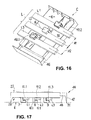
- the adapter C has an upper side 27 and an underside 28 opposite the upper side (cf. Fig. 17 ) on.
- the end wall 35 does not extend to the side walls 34.1, 34.2, but leaves in each case an input gap 39 to the guide channel 38.1, 38.2.
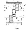
- the housing 1 has a bottom 10 located on the bottom 10, on the first sleeves 41.1, 41.2, to the Side walls 34.1, 34.2 adjacent second sleeves 42.1, 42.2 and two rectangular recesses 15.1, 15.2 are arranged.
- the recesses 15.1, 15.2 are each divided by a transverse rib 29 in two openings 30.1, 30.2 (see. Fig. 7 ), according to Fig. 6
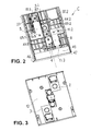
- the hook clamps 11.1, 11.3 and a middle hook clamp 11.2 are in Figures 2 and 17 to see.
- the sleeves 41.1, 41.2; 42.1, 42.2 extend to the top 27 of the adapter.
- connecting means such as screws, for non-positive connection of the adapter C with the lower part B are admitted.
- the sleeves 41.1, 41.2; 42.1, 42.2 on a bottom, in the middle of a small opening for carrying a screw tip is provided.
- the sleeves 41.1, 41.2; 42.1, 42.2 replaced by blind holes, the bottom of which is thin-walled and thus can be pierced by a screw.
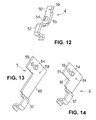
- Fig. 12 is a medium 4 complete bus bar Adapters shown, consist of a flat iron 50 and a sleeve-shaped connecting piece 54.
- the flat iron 50 is a continuous, communicating with the connecting piece 54 opening 55 and a mounting opening 56 is arranged.
- a flat iron 60 and 61 also carries the sleeve-shaped connecting piece 54 and has a bow 57, a mounting opening 58 and a further opening 59.
- the lateral busbars 5; 6 differed from each other in their total length.
- the middle busbar 4 is placed between the isolation partitions 44.1, 44.2 of the housing 1. There, it rests against the plate 45.1 and is helically connected via the mounting plate 56 lying on the flat iron with the sleeve-shaped mounting hole 52.2 of the housing 1. In this case, the arc 57 of the busbar 4 is supported on a recess 62 arranged between the isolation dividing walls 44.1, 44.2.
- the connecting piece 54 allows a screwing of the busbar with a complete contact 12 (see. Fig. 15 ).
- the connecting piece 54 optionally engages in one of the longitudinal symmetry line S arranged openings 43.1, 43.2 a.
- the busbars 5, 6 are based with their flat parts each in Fig. 6 shown walls 63.1, 63.2 and ribs 64.1, 64.2 of the housing 1 and are there fixed by means screwed into the mounting holes 58 of the busbar and mounting holes 53.1, 53.2 of the housing screws 65.1, 65.2.
- the connecting piece 54 can optionally be arranged on one of the openings 55, 59.
- FIGS. 8, 9, 10 and 11 show protective body 40.1, 40.2, which cover the recesses 15.1, 15.2 and the hook clamps 11.1, 11.3 (see. Figures 3 . 4 and 5 ).
- FIGS. 8, 9 and 10, 11 represented protective body 40.1, 40.2 has a protective element 7, 9 supporting, rectangular plate member 2; 3, on which an opening 14 for the passage of the hook clamp 11.1, 11.3 is arranged. This is parallel to the plate element 2; 3 arranged protective element 7; 9 in a right angle over the plate member 2; 3 projecting wall 12 via which with the plate member 2; 3 is connected.
- the protective element 7, 9 and the wall 12 are at their free edges with angled protective webs 17.1, 17.2, 17.3; 16.1, 16.2 provided so that the on the plate member 2; 3 projecting part of the protective body 40.1; 40.2 acts as a hood.
- a depression 66 introduced (see. FIGS. 8, 10 ), which at the top of the plate element (see. Figures 11 . 4 and 5 ) gives a survey 67.
- the arcs 57 of the busbars are based.
- the plate element 2; 3 has two mutually opposite locking ribs 21.1, 21.2 (see. Fig. 8 ) and four, in pairs on its longitudinal edges 24.1, 24.2 downwardly projecting, resilient Resting thumb 22.1, 22.1, 22.3, 22.4.
- the latching thumbs 22.1, 22.1, 22.3, 22.4 engage in the seating elements 25.1, 25.2, 25.3, 25.4 arranged at the inner edges 23.1, 23.2 of the recess 15.1, 15.2 (cf. Fig. 7 ) one.
- the plate element 2; 3 is a removable, plate-shaped masking element 18.1 located outside the opening 14; Arranged 18.2, which is connected to the rest of the plate element via circumferential predetermined breaking points 19. If necessary, the masking element 18.1; 18.2 be removed with a simple tool.
- the protective bodies 40.1, 40.2 differ from each other by the arrangement of the hood-shaped protective element 7, 9 with respect to the masking element 18.1, 18.2. This is clear from the FIGS. 9, 11 and 4, 5 to recognize.
- the protective element 7 with its protective web 17.3 points to the masking element 18.1, the wall 12 and the recess 66 or elevation 67 facing a narrow edge 68 of the plate element.
- the protective element 9 with its protective web 17.3 points to a narrow edge 69, the wall 12 and the recess 66 or elevation 67 facing the masking element 18.2. This allows a simple change of position of the protective body 40.1, 40.2 without rotation by 180 ° in the Adaptation to other busbar distances (cf. FIGS. 4 and 5 ).
- the entire protective body 40.1; 40.2 including locking ribs and locking thumb is made of polycarbonate in a piece of material by injection molding.
- the Fig. 16 shows the mounted on a busbar system L adapter C from below.
- the protective body 40.1 completely covers the hook clamp 11.3 embracing the busbar L3 (see in particular FIG Fig. 17 ).
- the protective body 40.2 covers the hook rail 11.1 embracing the busbar L1.
- the hook clamp 11.2 covering protective element 8 forms together with the wall 12 and the protective webs 16.1, 16.2; 17.1, 17.2, 17.3 another protective body 70.
- a plate element, as in the protective bodies 40.1, 40.2, is not present.
- the protective body 70 completely covers the hook rail 11.2 embracing the busbar L2.
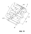
- the busbars L1, L2, L3, also of equal width, arranged in a larger busbar spacing A2 100 mm.
- the same protective body 40.1, 40.2 are used, being provided for the busbar L1 of the protective body 40.1 and for the busbar L3 of the protective body 40.2.
- guide elements 48 of an additional, front-side busbar shield 46 are inserted into the input gaps.
- the bus bar shield 46 made of electrically non-conductive plastic has two plate-shaped cover elements 47 lying perpendicular to one another; 49 and the mentioned guide elements 48.
- the extending in the inserted state parallel to the end wall 35 of the housing 1 cover 47 extends with its lower edge 51 approximately to a lowermost level E of the circuit breaker, by protective elements 7; 8th; 9 of the hook clamps 11 is defined.
Landscapes
- Engineering & Computer Science (AREA)
- Power Engineering (AREA)
- Distribution Board (AREA)
Abstract
Description
Die Erfindung betrifft einen kompakten Niederspannungs-Sicherheitstrennschalter, der aufweist:
- einen rippenkastenförmigen Adapter zum Aufsetzen auf ein dreiphasiges, aus Sammelschienen bestehendes Sammelschienensystem,
- über einen Boden des Adapters hinaus ragende Hakenklemmen, die zur Herstellung einer Strom- und Klemmverbindung der Sammelschienen mit den im Adapter befindlichen Stromschienen vorgesehen sind,
und wobei die Hakenklemmen jeweils durch ein elektrisch nichtleitendes Schutzelement wenigstens teilweise abgedeckt sind.The invention relates to a compact low-voltage safety circuit breaker comprising:
- a ribbed box-shaped adapter for mounting on a three-phase busbar system consisting of busbars,
- Hook clamps projecting beyond a bottom of the adapter and intended for producing a current and clamp connection of the busbars with the busbars located in the adapter,
and wherein the hook clamps are each at least partially covered by an electrically non-conductive protective element.
Ein Niederspannungs-Sicherheitstrennschalter der eingangs genannten Art, als Sicherungslasttrennschalter bezeichnet, ist aus
Es sind auch kompakte Sicherheitstrennschalter bekannt, bei denen das elektrisch nicht leitende Schutzelement für die Hakenklemme am Adapter des Sicherheitstrennschalters befestigt wird. Das Schutzelement ist für alle drei Phasen L1, L2, L3 identisch. Zwecks Anpassung des Trennschalters an einen anderen Sammelschienen-Abstand wird dasselbe Schutzelement an entsprechenden Stellen des Adapters befestigt, und die darin entstandenen freien Öffnungen werden mit Hilfe eines zusätzlichen Schutzelementes am Adapter maskiert.There are also compact safety disconnect switch are known in which the electrically non-conductive protective element for the hook clamp is attached to the adapter of the safety disconnect switch. The protection element is identical for all three phases L1, L2, L3. In order to adapt the circuit breaker to a different bus bar spacing, the same protective element is attached to corresponding points of the adapter, and the resulting free openings are masked by means of an additional protective element on the adapter.
Ferner sind Sicherheitstrennschalter bekannt, bei denen ein die Hakenklemme maskierendes Schutzelement am Adapter des Sicherheitstrennschalter befestigt ist. Auch hier ist das Schutzelement für alle drei Phasen L1, L2, L3 identisch. Solche Apparate haben jedoch keine Möglichkeit, den Sicherheitstrennschalter an einen anderen Sammelschienen-Abstand anzupassen.Furthermore, safety disconnect switches are known in which a masking the hook clamp protective element is attached to the adapter of the safety disconnector. Again, the protective element for all three phases L1, L2, L3 is identical. However, such devices have no way to adapt the safety disconnector to a different busbar distance.
Aus
Diese Konstruktion weicht jedoch vom Oberbegriff der vorliegenden Erfindung ab.However, this construction deviates from the preamble of the present invention.
Ein aus
Aufgabe der Erfindung ist, einen kompakten Niederspannungs-Sicherheitstrennschalter zu konzipieren, der einen verbesserten Schutz vor zufälligen Berührungen sowie vor Kurzschlüssen während der Montage am Sammelschienensystem bietet. Dabei soll der Niederspannungs-Sicherheitstrennschalter an verschiedene Sammelschienen-Abstände anpassbar sein, ohne Abstriche am verbesserten Schutz zu machen.The object of the invention is to design a compact low-voltage safety isolator, which offers improved protection against accidental touches as well as short circuits during mounting on the busbar system. The low-voltage safety isolator should be adaptable to different busbar distances without sacrificing improved protection.
Diese Aufgabe ist durch einen gattungsgemäßen kompakten Niederspannungs-Sicherheitstrennschalter gelöst, bei dem
- am Boden des Adapters wenigstens eine Aussparung zur Unterbringung eines Plattenelementes vorgesehen ist, das das Schutzelement trägt,
- an dem Plattenelement wenigstens eine Öffnung zur Durchführung der Hakenklemme angeordnet ist,
- und dass das Plattenelement mit seinem Schutzelement sowohl bei einem ersten Sammelschienen-Abstand als auch bei einem anderen, sich von dem ersten unterscheidenden Sammelschienen-Abstand an den Hakenklemmen der ersten und dritten Sammelschiene abwechselnd einsetzbar ist.
- at least one recess for accommodating a plate element, which carries the protective element, is provided at the bottom of the adapter,
- on the plate element at least one opening for the passage of the hook clamp is arranged,
- and that the plate member is alternately insertable with its protective member at both a first bus bar spacing and at another bus bar spacing different from the first one at the hook terminals of the first and third bus bars.
Es sei angemerkt, dass es sich bei dem kompakten Niederspannungs-Sicherheitstrennschalter, im Weiteren Trennschalter genannt, um ein Gerät handelt, das aus einem Adapter, einem auf den Adapter aufgesetzten Sicherungslastrenner und einem Deckel mit nebeneinander liegenden Sicherungseinsätzen besteht.It should be noted that it is the compact low-voltage safety disconnector, hereinafter called disconnector, is a device that consists of a Adapter, a mounted on the adapter fuse latch and a lid with adjacent fuse links.
Der Sammelschienen-Abstand wird normalerweise zwischen Längssymmetrielinien zweier benachbarten Sammelschienen bemessen, vorausgesetzt, dass das Breitenmaß der Sammelschienen gleich ist. Der Adapter gemäß Erfindung ist grundsätzlich für zwei Sammelschienen-Abstände von der Größe 60 mm und 100 mm gedacht. Die anderen Sammelschienen-Abstände, wiem 40 mm und 80 mm, sind nicht ausgeschlossen.The busbar spacing is normally sized between longitudinal symmetry lines of two adjacent busbars, provided that the width dimension of the busbars is the same. The adapter according to the invention is basically intended for two busbar spacings of the
Das die Hakenklemme abzudeckende Schutzelement kann mit dem Plattenelement verbunden sein und einen einheitlichen Schutzkörper bilden, der vorzugsweise aus einem Materialstück im Spritzgußverfahren gefertigt ist. Als Material für den Schutzkörper eignen sich insbesondere thermoplastische Kunststoffe, die sich durch verbesserte mechanische Eigenschaften, wie Härte und Stoßfestigkeit, sowie thermische Beständigkeit auszeichnen, beispielsweise Polycarbonate.The protective element to be covered by the hook clamp can be connected to the plate element and form a uniform protective body, which is preferably made of a piece of material by injection molding. Particularly suitable as material for the protective body are thermoplastics which are distinguished by improved mechanical properties, such as hardness and impact resistance, and thermal resistance, for example polycarbonates.
Vorzugsweise ist das über dem Plattenelement angeordnete Schutzelement haubenförmig ausgebildet, so dass die Hakenklemme vollständig abgedeckt werden kann. Dies ist von großem Vorteil, da dadurch die Gefahr einer zufälligen Berührung der Hakenklemmen nahezu ausgeschlossen ist.Preferably, the protective element arranged above the plate element is hood-shaped, so that the hook clamp can be completely covered. This is of great advantage since it virtually eliminates the risk of accidental contact with the hook clamps.
Der Schutzkörper kann mit dem Boden des Adapters verrastbar oder verschraubbar sein. Eine bevorzugte Rastverbindung kann federnde Stege, Laschen, Zungen oder Rastdaumen umfassen, die in entsprechende Nuten, Schlitze, Hülsen und Abstufungen des Gegenelementes eingreifen können.The protective body can be latched or screwed to the bottom of the adapter. A preferred latching connection may comprise resilient webs, tabs, tongues or latching thumbs, which may engage in corresponding grooves, slots, sleeves and gradations of the counter-element.
Die am Boden des Adapters angeordneten Aussparungen sowie die über den Boden ragenden Hakenklemmen können durch die abnehmbar befestigbaren, auswechselbaren Schutzkörper sowohl bei dem 60mm-Sammelschienen-Abstand als auch bei dem größeren, 100mm-Sammelschienen-Abstand abgedeckt sein, ohne den Aufbau des Adapters und der Schutzkörper in irgendeiner Weise verändern zu müssen.The arranged at the bottom of the adapter recesses and the protruding over the floor hook clamps can be covered by the removably attachable, interchangeable protective body at both the 60mm busbar distance and at the larger, 100mm busbar distance, without the structure to change the adapter and the protective body in any way.
Ein weiterer Vorteil ist, dass man für zwei Adapter für unterschiedliche Sammelschienen-Abstände nicht vier, sonder zwei auswechselbare Schutzkörper braucht. Der Einsatz eines Adapters für unterschiedliche Sammelschienen-Abstände ist auch möglich.Another advantage is that you do not need four, but two interchangeable protective body for two adapters for different busbar distances. The use of an adapter for different busbar distances is also possible.
Die Erfindung ist in einem Ausführungsbeispiel anhand der Zeichnung näher erläutert. Die Figuren zeigen:
- Fi.1
- einen kompletten Trennschalter in einer perspektivischen Ansicht;
- Fig. 2
- einen kompletten Adapter in einer perspektivischen Ansicht von oben;
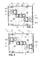
- Fig. 3
- den Adapter gemäß
Fig. 2 in einer perspektivischen Ansicht von unten; - Fig. 4
- den Adapter gemäß
Fig. 2 , für 60mm-Sammelschienen-Abstand, in einer schematischen Draufsicht auf den Boden des Adapters; - Fig. 5
- den Adapter gemäß
Fig. 2 , für 100mm-Sammelschienen-Abstand, in einer schematischen Draufsicht auf den Boden des Adapters; - Fig. 6
- ein Basisteil des Adapters, in einer perspektivischen Ansicht von oben;
- Fig. 7
- das Basisteil gemäß
Fig. 6 , in einer perspektivischen Ansicht von unten; - Fig. 8
- einen ersten Schutzkörper in einer perspektivischen Ansicht auf seine Unterseite;
- Fig. 9
- den Schutzkörper gemäß
Fig. 8 in einer perspektivischen Ansicht auf seine Oberseite; - Fig. 10
- einen zweiten Schutzkörper in einer perspektivischen Ansicht auf seine Unterseite;
- Fig. 11
- den Schutzkörper gemäß
Fig. 10 in einer perspektivischen Ansicht auf seine Oberseite; - Fig. 12
- eine mittlere Stromschiene des Adapters in einer perspektivischen Ansicht;
- Fig. 13
- eine seitliche Stromschiene für 100mm-Sammelschienen-Abstand, in einer perspektivischen Ansicht;
- Fig. 14
- eine seitliche Stromschiene für 60mm-Sammelschienen-Abstand, in einer perspektivischen Ansicht;
- Fig. 15
- einen kompletten Kontakt;
- Fig. 16
- den kompletten Adapter gemäß
Fig. 3 , aufgesetzt auf ein 60mm-Sammelschienesystem, in einer perspektivischen Ansicht von unten; - Fig. 17
- den Adapter gemäß
Fig. 16 in einer schematischen Seitenansicht; - Fig. 18
- den kompletten Adapter gemäß
Fig. 3 , aufgesetzt auf ein 100mm-Sammelschienesystem, in einer perspektivischen Ansicht von unten.
- Fi.1
- a complete circuit breaker in a perspective view;
- Fig. 2
- a complete adapter in a perspective view from above;
- Fig. 3
- the adapter according to
Fig. 2 in a perspective view from below; - Fig. 4
- the adapter according to
Fig. 2 , for 60mm busbar spacing, in a schematic plan view of the bottom of the adapter; - Fig. 5
- the adapter according to
Fig. 2 , for 100mm busbar spacing, in a schematic plan view of the bottom of the adapter; - Fig. 6
- a base part of the adapter, in a perspective view from above;
- Fig. 7
- the base part according to
Fig. 6 in a perspective view from below; - Fig. 8
- a first protective body in a perspective view on its underside;
- Fig. 9
- the protective body according to
Fig. 8 in a perspective view on its top side; - Fig. 10
- a second protective body in a perspective view on its underside;
- Fig. 11
- the protective body according to
Fig. 10 in a perspective view on its top side; - Fig. 12
- a middle busbar of the adapter in a perspective view;
- Fig. 13
- a lateral bus bar for 100mm busbar spacing, in a perspective view;
- Fig. 14
- a side busbar for 60mm busbar spacing, in a perspective view;
- Fig. 15
- a complete contact;
- Fig. 16
- the complete adapter according to
Fig. 3 mounted on a 60mm busbar system, in a perspective view from below; - Fig. 17
- the adapter according to
Fig. 16 in a schematic side view; - Fig. 18
- the complete adapter according to
Fig. 3 , mounted on a 100mm busbar system, in a perspective view from below.
In
Die Worte: "oben", "unten" beziehen sich auf die
Der komplette Schaltdeckel D ist schwenkbar am Unterteil B angebracht. Er weist einen Schaltgriff 13 zum Heben des Deckels um eine an sich bekannte, nicht dargestellte Drehachse auf. Ferner weist der komplette Schaltdeckel D drei nebeneinander liegende, etwa trapezförmige, transparente Scheiben 31 mit mittleren Schiebern 32 und entsprechenden Prüföffnungen 33 für Prüfwerkzeug auf. Beim aufgesetzten, verschlossenen Schaltdeckel D besteht eine elektrische Verbindung zwischen Eingangs- und Abgangsanschlüssen. Hierfür sind nicht dargestellte, unterhalb der Scheiben 31 befindliche Sicherungseinsätze vorgesehen.The complete shift cover D is pivotally mounted on the lower part B. It has a
Das komplette Unterteil B ist nur schematisch in
Der Adapter C weist ein in den
Innerhalb des Gehäuses 1 verlaufen parallel und in einem geringen Abstand zu den Seitenwänden 34.1, 34.2 zwei Innenstege 37.1, 37.2, die jeweils einen im vorderen Teil des Gehäuses 1 verlaufenden Führungskanal 38.1, 38.2 bilden. Die Stirnwand 35 reicht bis zu den Seitenwänden 34.1, 34.2 nicht, sondern belässt jeweils eine Eingangslücke 39 zum Führungskanal 38.1, 38.2.Within the housing 1 run parallel and at a small distance from the side walls 34.1, 34.2 two inner webs 37.1, 37.2, each forming a running in the front part of the housing 1 guide channel 38.1, 38.2. The
Weiterhin weist das Gehäuse 1 einen auf dessen Unterseite 28 liegenden Boden 10 auf, an dem erste Hülsen 41.1, 41.2, an den Seitenwänden 34.1, 34.2 anliegende zweite Hülsen 42.1, 42.2 sowie zwei rechteckige Aussparungen 15.1, 15.2 angeordnet sind. Die Aussparungen 15.1, 15.2 sind jeweils durch eine Querrippe 29 in zwei Öffnungen 30.1, 30.2 geteilt (vgl.
Die Hülsen 41.1, 41.2; 42.1, 42.2 reichen bis zur Oberseite 27 des Adapters. In die Hülsen 41.1, 41.2; 42.1, 42.2 werden Verbindungsmittel, wie Schrauben, zur kraftschlüssigen Verbindung des Adapters C mit dem Unterteil B eingelassen.Furthermore, the housing 1 has a bottom 10 located on the bottom 10, on the first sleeves 41.1, 41.2, to the Side walls 34.1, 34.2 adjacent second sleeves 42.1, 42.2 and two rectangular recesses 15.1, 15.2 are arranged. The recesses 15.1, 15.2 are each divided by a
The sleeves 41.1, 41.2; 42.1, 42.2 extend to the top 27 of the adapter. In the sleeves 41.1, 41.2; 42.1, 42.2 connecting means, such as screws, for non-positive connection of the adapter C with the lower part B are admitted.
In einem nicht dargestellten, zweiten Ausführungsbeispiel weisen die Hülsen 41.1, 41.2; 42.1, 42.2 einen Boden auf, in dessen Mitte eine kleine Öffnung zur Durchführung einer Schraubenspitze vorgesehen ist.In a second embodiment, not shown, the sleeves 41.1, 41.2; 42.1, 42.2 on a bottom, in the middle of a small opening for carrying a screw tip is provided.
In einem weiteren, nicht dargestellten Ausführungsbeispiel sind die Hülsen 41.1, 41.2; 42.1, 42.2 durch Sacklöcher ersetzt, deren Boden dünnwändig ist und dadurch von einer Schraube durchgestochen werden kann.In a further, not shown embodiment, the sleeves 41.1, 41.2; 42.1, 42.2 replaced by blind holes, the bottom of which is thin-walled and thus can be pierced by a screw.
Längs einer Symmetrielinie S des Gehäuses 1 und innerhalb zweier parallel zur Symmetrielinie verlaufenden Isolationstrennwänden 44.1, 44.2 liegen voneinander beabstandet zwei Plättchen 45.1, 45.2 (vgl.
In
Ähnlich sind die seitlichen kompletten Stromschienen 5, 6 (vgl.
Gemäß
Die Stromschienen 5, 6 stützen sich mit ihren flachen Teilen jeweils an in
Ferner erkennt man in
Die
Der in
Das Schutzelement 7, 9 und die Wand 12 sind an ihren freien Kanten mit abgewinkelten Schutzstegen 17.1, 17.2, 17.3; 16.1, 16.2 versehen, so dass das über das Plattenelement 2; 3 ragende Teil des Schutzkörpers 40.1; 40.2 als Haube wirkt. Im Übergangsbereich der Wand 12 zum Plattenelement 2; 3 ist am Plattenelement 2; 3 eine Vertiefung 66 eingebracht (vgl.
Das Plattenelement 2; 3 weist zwei sich gegenüber liegende Rastrippen 21.1, 21.2 (vgl.
Ebenso sind die Längskanten 24.1, 24.2 und die Rastrippen 21.1, 21.2 des Plattenelementes 2; 3 zu den abgestuften Innenkanten 23.1, 23.2 der Aussparungen 15.1, 15.2 kompatibel, so dass das in die Aussparung 15.1, 15.2 eingedrückte Plattenelement 2; 3 mit dem Boden 10 des Adapters C fluchtet. Wie die
An dem Plattenelement 2; 3 ist ein außerhalb der Öffnung 14 liegendes, entfernbares, plattenförmiges Maskierungselement 18.1; 18.2 angeordnet, das mit dem restlichen Plattenelement über umlaufende Sollbruchstellen 19 verbunden ist. Nach Bedarf kann das Maskierungselement 18.1; 18.2 mit einem einfachen Werkzeug entfernt werden.On the
Die Schutzkörper 40.1, 40.2 unterscheiden sich voneinander durch die Anordnung des haubenförmigen Schutzelementes 7, 9 gegenüber dem Maskierungselement 18.1, 18.2. Dies ist deutlich aus den
Der gesamte Schutzkörper 40.1; 40.2 samt Rastrippen und Rastdaumen ist aus Polycarbonat in einem Materialstück im Spritzgußverfahren hergestellt.The entire protective body 40.1; 40.2 including locking ribs and locking thumb is made of polycarbonate in a piece of material by injection molding.
Die
Gemäß
According to
Aus den
Dementsprechend decken die Schutzkörper 40.1; 40.2 die in den Öffnungen 30.1 befindlichen Hakenklemmen 11.1, 11.3 für den Sammelschienen-Abstand A1 = 100 mm und zugleich die für den anderen Sammelschienen-Abstand A1 = 60mm vorgesehenen Öffnungen 30.2 ab.Accordingly, cover the protective body 40.1; 40.2 located in the openings 30.1 hook terminals 11.1, 11.3 for the busbar distance A1 = 100 mm and at the same time provided for the other busbar distance A1 = 60mm openings 30.2 from.
Gemäß
- 11
- Gehäusecasing
- 2; 32; 3
- Plattenkörperplate body
- 4; 5; 64; 5; 6
- Stromschieneconductor rail
- 7; 8; 97; 8th; 9
- Schutzelementprotection element
- 1010
- Bodenground
- 11.1; 11.2, 11.311.1; 11.2, 11.3
- Hakenklemmehook clip
- 1212
- Wandwall
- 1313
- Schaltgriffshifter
- 1414
- Öffnungopening
- 15.1, 15.215.1, 15.2
- Aussparung (v. 10)Recess (v. 10)
- 16.1, 16.216.1, 16.2
- Schutzstegguard bar
- 17.1, 17.2, 17.317.1, 17.2, 17.3
- Schutzstegguard bar
- 18.1, 18.218.1, 18.2
- Maskierungselementmasking element
- 1919
- SollbruchstelleBreaking point
- 20.1, 20.220.1, 20.2
- SitzSeat
- 20.3, 20.420.3, 20.4
- SitzSeat
- 21.1, 21.221.1, 21.2
- Rastrippelocking rib
- 22.1, 22.122.1, 22.1
- RastdaumenRest your thumb
- 22.3, 22.422.3, 22.4
- RastdaumenRest your thumb
- 23.1, 23.223.1, 23.2
- Innenkanteinner edge
- 24.1, 24.224.1, 24.2
- Längskantelongitudinal edge
- 25.1, 25.225.1, 25.2
- Sitzelementseat element
- 25.3, 25.425.3, 25.4
- Sitzelementseat element
- 2626
- Teilhülsepart sleeve
- 2727
- Oberseitetop
- 2828
- Unterseitebottom
- 2929
- Querrippetransverse rib
- 30.1, 30.230.1, 30.2
- Öffnung (v. Aussparung)Opening (by recess)
- 3131
- Scheibedisc
- 3232
- Schieberpusher
- 3333
- Prüföffnungtest opening
- 34.1, 34.234.1, 34.2
- SeitenwandSide wall
- 3535
- Stirnwandbulkhead
- 3636
- hintere Wand (v.1)rear wall (v.1)
- 37.1, 37.237.1, 37.2
- Innensteginner web
- 38.1, 38.238.1, 38.2
- Führungskanalguide channel
- 3939
- Eingangslückeentrance gap
- 40.1, 40.240.1, 40.2
- Schutzkörperprotective body
- 41.1, 41.241.1, 41.2
- Hülseshell
- 42.1, 42.242.1, 42.2
- Hülseshell
- 43.1, 43.243.1, 43.2
- Öffnungopening
- 44.1, 44.244.1, 44.2
- Isolationstrennwandinsulating partition wall
- 45.1, 45.245.1, 45.2
- PlättchenTile
- 4646
- SammelschienenabschirmungBusbar shield
- 4747
- Abdeckelementcover
- 4848
- Führungselementguide element
- 4949
- Abdeckelementcover
- 5050
- Flacheisenflat iron
- 5151
- Kanteedge
- 52.1, 52.252.1, 52.2
- Montageöffnungmounting hole
- 53.1, 53.253.1, 53.2
- Montageöffnungmounting hole
- 5454
- Verbindungsstückjoint
- 5555
- Öffnungopening
- 5656
- Montageöffnungmounting hole
- 5757
- Bogenbow
- 5858
- Montageöffnungmounting hole
- 5959
- Öffnungopening
- 60; 6160; 61
- Flacheisenflat iron
- 6262
- Eintiefungdepression
- 63.1, 63.263.1, 63.2
- Ripperib
- 64.1, 64.264.1, 64.2
- Ripperib
- 65.1, 65.265.1, 65.2
- Schraubescrew
- 6666
- Eintiefungdepression
- 6767
- Erhebungsurvey
- 6868
- Schmalkantenarrow edge
- 6969
- Schmalkantenarrow edge
- 7070
- Schutzkörperprotective body
- 100100
- SicherheitstrennschalterSafety cutout switch
- A1; A2A1; A2
- Sammelschienen-AbstandBusbar distance
- BB
- Unterteillower part
- CC
- Adapteradapter
- DD
- Schaltdeckelswitch cover
- Ee
- Ebenelevel
- LL
- SammelschienensystemBusbar system
- L1, L2, L3L1, L2, L3
- Sammelschienebus
- SS
- Symmetrielinieline of symmetry
Claims (12)
und wobei die Hakenklemmen (11.1; 11.2, 11.3) jeweils durch ein elektrisch nichtleitendes Schutzelement (7; 8; 9) wenigstens teilweise abgedeckt sind,
dadurch gekennzeichnet, dass
and wherein the hook clamps (11.1; 11.2, 11.3) are each at least partially covered by an electrically non-conductive protective element (7; 8; 9),
characterized in that
Applications Claiming Priority (1)
| Application Number | Priority Date | Filing Date | Title |
|---|---|---|---|
| PL383126A PL383126A1 (en) | 2007-08-13 | 2007-08-13 | Low voltage compact fuse disconnector and the manner of fixing shields with a hook clamp in low voltage compact fuse disconnector |
Publications (1)
| Publication Number | Publication Date |
|---|---|
| EP2026429A1 true EP2026429A1 (en) | 2009-02-18 |
Family
ID=40011305
Family Applications (1)
| Application Number | Title | Priority Date | Filing Date |
|---|---|---|---|
| EP08014360A Withdrawn EP2026429A1 (en) | 2007-08-13 | 2008-08-12 | Compact low-voltage safety breaker with completely covered suspension catches |
Country Status (2)
| Country | Link |
|---|---|
| EP (1) | EP2026429A1 (en) |
| PL (1) | PL383126A1 (en) |
Cited By (4)
| Publication number | Priority date | Publication date | Assignee | Title |
|---|---|---|---|---|
| EP2654147A3 (en) * | 2012-04-20 | 2014-03-19 | Wöhner GmbH & Co. KG Elektrotechnische Systeme | Busbar adapter |
| EP2733801A1 (en) * | 2012-11-14 | 2014-05-21 | Apator S.A. | Isolating switch with rail module |
| CN104078851A (en) * | 2014-07-18 | 2014-10-01 | 国家电网公司 | KYN-type high-voltage measuring cabinet |
| EP2793332A1 (en) * | 2013-04-19 | 2014-10-22 | Jean Müller GmbH Elektrotechnische Fabrik | Electric installation device |
Citations (7)
| Publication number | Priority date | Publication date | Assignee | Title |
|---|---|---|---|---|
| DE4003260C2 (en) | 1990-02-03 | 2001-04-12 | Efen Elektrotech Fab | Adapter for busbar systems |
| DE10062634A1 (en) | 2000-12-15 | 2002-06-27 | Mueller Jean Ohg Elektrotech | Holder for a hook clamp |
| EP1271727A1 (en) | 2001-06-22 | 2003-01-02 | Weber AG | Electrical installation apparatus |
| EP1508949A1 (en) * | 2003-08-18 | 2005-02-23 | M. Schneider, Schaltgerätebau und Elektroinstallationen Gesellschaft m.b.H. | Low-voltage high-power fuse device |
| DE202005013446U1 (en) * | 2005-08-19 | 2005-11-03 | Siemens Ag | Rear-side insulating cover plate for safety circuit-breaker, has plate body with hooks for fixing plate to bus bar, where hooks are guidable through respective window in body, which is fastened to rear-side of circuit-breaker |
| DE102005012364A1 (en) | 2005-03-10 | 2006-09-14 | Siemens Ag | Latch hook for a switch-disconnector |
| EP1760853A1 (en) * | 2005-09-05 | 2007-03-07 | Siemens Aktiengesellschaft | A device for fixing a load break switch with fuses to a busbar |
-
2007
- 2007-08-13 PL PL383126A patent/PL383126A1/en not_active IP Right Cessation
-
2008
- 2008-08-12 EP EP08014360A patent/EP2026429A1/en not_active Withdrawn
Patent Citations (7)
| Publication number | Priority date | Publication date | Assignee | Title |
|---|---|---|---|---|
| DE4003260C2 (en) | 1990-02-03 | 2001-04-12 | Efen Elektrotech Fab | Adapter for busbar systems |
| DE10062634A1 (en) | 2000-12-15 | 2002-06-27 | Mueller Jean Ohg Elektrotech | Holder for a hook clamp |
| EP1271727A1 (en) | 2001-06-22 | 2003-01-02 | Weber AG | Electrical installation apparatus |
| EP1508949A1 (en) * | 2003-08-18 | 2005-02-23 | M. Schneider, Schaltgerätebau und Elektroinstallationen Gesellschaft m.b.H. | Low-voltage high-power fuse device |
| DE102005012364A1 (en) | 2005-03-10 | 2006-09-14 | Siemens Ag | Latch hook for a switch-disconnector |
| DE202005013446U1 (en) * | 2005-08-19 | 2005-11-03 | Siemens Ag | Rear-side insulating cover plate for safety circuit-breaker, has plate body with hooks for fixing plate to bus bar, where hooks are guidable through respective window in body, which is fastened to rear-side of circuit-breaker |
| EP1760853A1 (en) * | 2005-09-05 | 2007-03-07 | Siemens Aktiengesellschaft | A device for fixing a load break switch with fuses to a busbar |
Cited By (5)
| Publication number | Priority date | Publication date | Assignee | Title |
|---|---|---|---|---|
| EP2654147A3 (en) * | 2012-04-20 | 2014-03-19 | Wöhner GmbH & Co. KG Elektrotechnische Systeme | Busbar adapter |
| US9106033B2 (en) | 2012-04-20 | 2015-08-11 | Woehner Gmbh & Co. Kg Elektrotechnische Systeme | Busbar adapter |
| EP2733801A1 (en) * | 2012-11-14 | 2014-05-21 | Apator S.A. | Isolating switch with rail module |
| EP2793332A1 (en) * | 2013-04-19 | 2014-10-22 | Jean Müller GmbH Elektrotechnische Fabrik | Electric installation device |
| CN104078851A (en) * | 2014-07-18 | 2014-10-01 | 国家电网公司 | KYN-type high-voltage measuring cabinet |
Also Published As
| Publication number | Publication date |
|---|---|
| PL383126A1 (en) | 2009-02-16 |
Similar Documents
| Publication | Publication Date | Title |
|---|---|---|
| EP0181534A1 (en) | Vehicle arrangement | |
| EP3111515B1 (en) | Terminal strip and terminal strip block | |
| EP2614515B1 (en) | Switching device and accessory on the connecting side | |
| DE202013003925U1 (en) | Additional socket and plug socket assembly manufacturable with it | |
| DE10237701B4 (en) | Connecting terminal for single, stranded, in particular finely stranded, electrical conductors | |
| EP2026429A1 (en) | Compact low-voltage safety breaker with completely covered suspension catches | |
| EP0889550B1 (en) | Covering for terminals with a protective cover | |
| DE202007018653U1 (en) | switchgear | |
| EP0240916B1 (en) | Domestic installation equipment for cable conduits | |
| DE3807191C2 (en) | Screw connection device for electrical conductors | |
| EP1199774B1 (en) | Electrical terminal block for side by side mounting in particular multi-level terminal block | |
| EP2023364B1 (en) | Electromagnetic switching device with several areas graded relative to one another | |
| WO2000028799A1 (en) | Modular system for electrical printed-circuit boards with centering contacts on front elements and separate locating contacts, notably with contact blades in the rack assembly | |
| DE19530659C1 (en) | Low voltage busbar system | |
| DE102008014180A1 (en) | Disconnect terminal i.e. neutral disconnect terminal, has disconnect slider that is slidable between two end positions by rotary motion of actuating tool, and actuation opening that serves as support for tool | |
| EP2982013B1 (en) | Electrical cabinet arrangement with connected protected areas | |
| DE102015116716A1 (en) | Distribution block with contact protection arrangement | |
| EP3211650B1 (en) | Load disconnector | |
| DE2313245C3 (en) | Electrical safety switch | |
| EP0890971B1 (en) | Cover for contacts for fuses in devices with low voltage high power fuses | |
| EP0555665B1 (en) | Outlet box, especially for busways | |
| EP1232509B1 (en) | Low-voltage circuit-breaker with a housing having a front panel and a back panel | |
| EP2019465B1 (en) | Compact low-voltage safety breaker | |
| DE10216371A1 (en) | auxiliary switch | |
| EP2209012A2 (en) | Adapter component for attachment to a supporting plate of a metering place installation |
Legal Events
| Date | Code | Title | Description |
|---|---|---|---|
| PUAI | Public reference made under article 153(3) epc to a published international application that has entered the european phase |
Free format text: ORIGINAL CODE: 0009012 |
|
| AK | Designated contracting states |
Kind code of ref document: A1 Designated state(s): AT BE BG CH CY CZ DE DK EE ES FI FR GB GR HR HU IE IS IT LI LT LU LV MC MT NL NO PL PT RO SE SI SK TR |
|
| AX | Request for extension of the european patent |
Extension state: AL BA MK RS |
|
| 17P | Request for examination filed |
Effective date: 20090505 |
|
| 17Q | First examination report despatched |
Effective date: 20090720 |
|
| AKX | Designation fees paid |
Designated state(s): AT BE BG CH CY CZ DE DK EE ES FI FR GB GR HR HU IE IS IT LI LT LU LV MC MT NL NO PL PT RO SE SI SK TR |
|
| STAA | Information on the status of an ep patent application or granted ep patent |
Free format text: STATUS: THE APPLICATION IS DEEMED TO BE WITHDRAWN |
|
| 18D | Application deemed to be withdrawn |
Effective date: 20150303 |