EP2026044B1 - End piece for a metering device for dosing a fluid - Google Patents
End piece for a metering device for dosing a fluid Download PDFInfo
- Publication number
- EP2026044B1 EP2026044B1 EP20070113872 EP07113872A EP2026044B1 EP 2026044 B1 EP2026044 B1 EP 2026044B1 EP 20070113872 EP20070113872 EP 20070113872 EP 07113872 A EP07113872 A EP 07113872A EP 2026044 B1 EP2026044 B1 EP 2026044B1
- Authority
- EP
- European Patent Office
- Prior art keywords
- end piece
- metering
- coupling means
- fluid
- cone
- Prior art date
- Legal status (The legal status is an assumption and is not a legal conclusion. Google has not performed a legal analysis and makes no representation as to the accuracy of the status listed.)
- Active
Links
- 239000012530 fluid Substances 0.000 title claims description 35
- 230000008878 coupling Effects 0.000 claims description 51
- 238000010168 coupling process Methods 0.000 claims description 51
- 238000005859 coupling reaction Methods 0.000 claims description 51
- 238000001514 detection method Methods 0.000 claims description 5
- 238000007789 sealing Methods 0.000 claims description 5
- 239000007822 coupling agent Substances 0.000 description 4
- 239000000853 adhesive Substances 0.000 description 3
- 230000001070 adhesive effect Effects 0.000 description 3
- 229920001971 elastomer Polymers 0.000 description 3
- 239000003973 paint Substances 0.000 description 3
- 238000011161 development Methods 0.000 description 2
- 239000000806 elastomer Substances 0.000 description 2
- 239000000839 emulsion Substances 0.000 description 2
- 239000003925 fat Substances 0.000 description 2
- 238000002347 injection Methods 0.000 description 2
- 239000007924 injection Substances 0.000 description 2
- 239000002994 raw material Substances 0.000 description 2
- 239000000565 sealant Substances 0.000 description 2
- 239000000725 suspension Substances 0.000 description 2
- 229920001651 Cyanoacrylate Polymers 0.000 description 1
- 239000000654 additive Substances 0.000 description 1
- 230000000996 additive effect Effects 0.000 description 1
- 239000013466 adhesive and sealant Substances 0.000 description 1
- NLCKLZIHJQEMCU-UHFFFAOYSA-N cyano prop-2-enoate Chemical class C=CC(=O)OC#N NLCKLZIHJQEMCU-UHFFFAOYSA-N 0.000 description 1
- 230000001419 dependent effect Effects 0.000 description 1
- 238000013461 design Methods 0.000 description 1
- 238000007599 discharging Methods 0.000 description 1
- 230000000694 effects Effects 0.000 description 1
- 239000003822 epoxy resin Substances 0.000 description 1
- LNEPOXFFQSENCJ-UHFFFAOYSA-N haloperidol Chemical compound C1CC(O)(C=2C=CC(Cl)=CC=2)CCN1CCCC(=O)C1=CC=C(F)C=C1 LNEPOXFFQSENCJ-UHFFFAOYSA-N 0.000 description 1
- 238000009434 installation Methods 0.000 description 1
- 230000010354 integration Effects 0.000 description 1
- 238000000034 method Methods 0.000 description 1
- 238000012986 modification Methods 0.000 description 1
- 230000004048 modification Effects 0.000 description 1
- 229920000647 polyepoxide Polymers 0.000 description 1
- 229920001296 polysiloxane Polymers 0.000 description 1
- 229920002635 polyurethane Polymers 0.000 description 1
- 239000004814 polyurethane Substances 0.000 description 1
- 238000004382 potting Methods 0.000 description 1
- 230000002250 progressing effect Effects 0.000 description 1
- 230000035484 reaction time Effects 0.000 description 1
- 229920002631 room-temperature vulcanizate silicone Polymers 0.000 description 1
- 229910000679 solder Inorganic materials 0.000 description 1
- 239000000243 solution Substances 0.000 description 1
- 238000012549 training Methods 0.000 description 1
Images


Classifications
-
- G—PHYSICS
- G01—MEASURING; TESTING
- G01F—MEASURING VOLUME, VOLUME FLOW, MASS FLOW OR LIQUID LEVEL; METERING BY VOLUME
- G01F11/00—Apparatus requiring external operation adapted at each repeated and identical operation to measure and separate a predetermined volume of fluid or fluent solid material from a supply or container, without regard to weight, and to deliver it
- G01F11/02—Apparatus requiring external operation adapted at each repeated and identical operation to measure and separate a predetermined volume of fluid or fluent solid material from a supply or container, without regard to weight, and to deliver it with measuring chambers which expand or contract during measurement
- G01F11/021—Apparatus requiring external operation adapted at each repeated and identical operation to measure and separate a predetermined volume of fluid or fluent solid material from a supply or container, without regard to weight, and to deliver it with measuring chambers which expand or contract during measurement of the piston type
- G01F11/029—Apparatus requiring external operation adapted at each repeated and identical operation to measure and separate a predetermined volume of fluid or fluent solid material from a supply or container, without regard to weight, and to deliver it with measuring chambers which expand or contract during measurement of the piston type provided with electric controlling means
-
- F—MECHANICAL ENGINEERING; LIGHTING; HEATING; WEAPONS; BLASTING
- F04—POSITIVE - DISPLACEMENT MACHINES FOR LIQUIDS; PUMPS FOR LIQUIDS OR ELASTIC FLUIDS
- F04C—ROTARY-PISTON, OR OSCILLATING-PISTON, POSITIVE-DISPLACEMENT MACHINES FOR LIQUIDS; ROTARY-PISTON, OR OSCILLATING-PISTON, POSITIVE-DISPLACEMENT PUMPS
- F04C2/00—Rotary-piston machines or pumps
- F04C2/08—Rotary-piston machines or pumps of intermeshing-engagement type, i.e. with engagement of co-operating members similar to that of toothed gearing
- F04C2/10—Rotary-piston machines or pumps of intermeshing-engagement type, i.e. with engagement of co-operating members similar to that of toothed gearing of internal-axis type with the outer member having more teeth or tooth-equivalents, e.g. rollers, than the inner member
- F04C2/107—Rotary-piston machines or pumps of intermeshing-engagement type, i.e. with engagement of co-operating members similar to that of toothed gearing of internal-axis type with the outer member having more teeth or tooth-equivalents, e.g. rollers, than the inner member with helical teeth
- F04C2/1071—Rotary-piston machines or pumps of intermeshing-engagement type, i.e. with engagement of co-operating members similar to that of toothed gearing of internal-axis type with the outer member having more teeth or tooth-equivalents, e.g. rollers, than the inner member with helical teeth the inner and outer member having a different number of threads and one of the two being made of elastic materials, e.g. Moineau type
-
- F—MECHANICAL ENGINEERING; LIGHTING; HEATING; WEAPONS; BLASTING
- F04—POSITIVE - DISPLACEMENT MACHINES FOR LIQUIDS; PUMPS FOR LIQUIDS OR ELASTIC FLUIDS
- F04C—ROTARY-PISTON, OR OSCILLATING-PISTON, POSITIVE-DISPLACEMENT MACHINES FOR LIQUIDS; ROTARY-PISTON, OR OSCILLATING-PISTON, POSITIVE-DISPLACEMENT PUMPS
- F04C2220/00—Application
- F04C2220/24—Application for metering throughflow
Definitions
- the technical field of the invention relates to the metering of fluids or fluid media, such as adhesives or sealants, paints, suspensions, viscous raw materials, emulsions or fats.
- Dosing devices which are suitable for such a dosage can be based on a gear pump or an eccentric screw pump or designed, for example, as a spindle conveyor.
- Such a metering device can also be designed as a valve, for example as a spindle valve, as a pressure-time valve or as a volume valve.
- the publication DE 20 2004 002 167 U1 which is considered to be the closest prior art, describes a metering valve for discharging minute amounts of medium onto a workpiece in the jet process, with a valve head having an outlet opening and a valve element associated therewith for opening and closing the outlet opening, and a jet device associated with the valve head, by means of which the medium in the form of droplets and / or jetsrank think- from the valve head or is injectable, with a dispensing needle sits on the valve head, which is designed in the manner of a nozzle such that the medium in the form of droplets and / or Rays from the dispensing needle can be ejected.
- Another object is to provide a solution that is as simple as possible and / or minimized in terms of the necessary installation space To suggest detection of disturbances during metering of the fluid through the metering device.
- the third coupling means and the fourth coupling means form a screw connection.
- the end piece is adapted to tension a stator of an eccentric screw pump of the metering device.
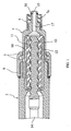
- All embodiments of the invention according to the Fig. 1 to 6 have in common that the tail 1, a first coupling means 3, which is adapted to couple the tail 1 with the metering device 2, an integrated needle adapter 4, which is adapted to couple a dispensing needle with the end piece 1, and an integrated pressure sensor device 5 or a second coupling means 6, which is adapted to couple the end piece 1 with the pressure sensor device 5.
- the third coupling means 7a are configured as a female luer taper 7a and the fourth coupling means 8a are designed as a male male tapered luer cone 8a.
- a channel 17 is provided for performing the funded by the metering device 2 fluid in the dispensing needle at least in the Luer cone 7a with female inner cone.
- the channel 17 preferably has at its outer diameter a groove 15 and an O-ring 16 arranged in the groove 15 for sealing the Luer-lock 7a formed from the Luer cone 7a with a female inner cone and from the Luer cone 7b with a male outer cone. 8a on.
- the O-ring 16 is made of, for example, an elastomer or rubber.
- the pressure sensor is particularly suitable for measuring a metering pressure during metering of the fluid. Furthermore, the detection means is preferably suitable for detecting a disturbance, for example an air bubble in the fluid or a fluctuation of the metering pressure, as a function of the measured metering pressure.
- Fig. 6 is a schematic perspective view of a fourth embodiment of the end piece 1 according to the invention shown.
- the fourth embodiment according to Fig. 6 differs from the third embodiment according to Fig. 5 in that not a second coupling means 6 is provided for coupling a pressure sensor device 5, but that the pressure sensor device 5 is integrated in the end piece 1.
- the end piece 1 according to Fig. 6 in addition to the first coupling means 3, which may be formed in particular as a connector on an outer diameter of the pressure sensor device 2, an integrated needle adapter 4 for coupling the dispensing needle and an integrated pressure sensor device 5.
Description
Die Erfindung betrifft ein Endstück für eine Dosiervorrichtung zum Dosieren eines Fluids.The invention relates to an end piece for a metering device for metering a fluid.
Das technische Gebiet der Erfindung betrifft die Dosierung von Fluiden oder fluiden Medien, wie beispielsweise Kleb- oder Dichtstoffen, Farben, Suspensionen, viskosen Rohstoffen, Emulsionen oder Fetten. Dosiervorrichtungen, welche für eine solche Dosierung geeignet sind, können auf einer Zahnradpumpe oder einer Exzenterschneckenpumpe basieren oder beispielsweise als eine Spindelfördereinrichtung ausgebildet sein. Eine solche Dosiervorrichtung kann auch als Ventil, beispielsweise als Spindelventil, als Druck-Zeit-Ventil oder als Volumenventil ausgebildet sein.The technical field of the invention relates to the metering of fluids or fluid media, such as adhesives or sealants, paints, suspensions, viscous raw materials, emulsions or fats. Dosing devices which are suitable for such a dosage can be based on a gear pump or an eccentric screw pump or designed, for example, as a spindle conveyor. Such a metering device can also be designed as a valve, for example as a spindle valve, as a pressure-time valve or as a volume valve.
Um kleine Mengen oder Kleinstmengen des Fluides zu dosieren, werden Dosiernadeln eingesetzt. Die einzusetzende Dosiernadel wird mit der jeweiligen Dosiervorrichtung gekoppelt. Für diese Koppelung ist der Anmelderin intern ein aufschraubbarer Adapter bekannt, welcher auf einen Endstutzen der Dosiervorrichtung aufgeschraubt wird. Der verschraubbare Adapter weist beispielsweise die Dosiernadel auf.In order to dose small amounts or very small amounts of fluid, dispensing needles are used. The dispensing needle to be used is coupled to the respective metering device. For this coupling, the Applicant internally a screw-adapter is known, which is screwed onto an end of the metering device. The screw-on adapter has, for example, the dispensing needle.
Nachteiligerweise kann aber bei der Verschraubung des Adapters mit der Dosiervorrichtung ein Totraum entstehen. Der entstandene Totraum kann die Wiederholbarkeit und/oder die Steuerbarkeit der Dosierung verschlechtern.Disadvantageously, however, a dead space can arise during the screwing of the adapter to the metering device. The resulting dead space can degrade the repeatability and / or the controllability of the dosage.
Des Weiteren ist ein solcher entstandener Totraum nachteilig, wenn das dosierte Fluid oder das dosierte fluide Medium zurückgesaugt werden soll, weil dann die Wahrscheinlichkeit für eine Blasenbildung im Kopplungsabschnitt zwischen dem Adapter und der Dosiervorrichtung deutlich erhöht ist.Furthermore, such a resulting dead space is disadvantageous if the metered fluid or the metered fluid medium to be sucked back, because then the probability of blistering in the coupling section between the adapter and the metering device is significantly increased.
Die Druckschrift
Ferner zeigt die Druckschrift
Des Weiteren sind Dosiervorrichtungen aus der
Demnach ist es eine Aufgabe der vorliegenden Erfindung, den Totraum bei der Kopplung der Dosiervorrichtung mit der Dosiernadel zu reduzieren oder zu minimieren.Accordingly, it is an object of the present invention to reduce or minimize the dead space in the coupling of the metering device with the dispensing needle.
Eine weitere Aufgabe ist es, eine möglichst einfache und/oder hinsichtlich des notwendigen Bauraums minimierte Lösung zur Detektion von Störungen beim Dosieren des Fluids durch die Dosiervorrichtung vorzuschlagen.Another object is to provide a solution that is as simple as possible and / or minimized in terms of the necessary installation space To suggest detection of disturbances during metering of the fluid through the metering device.
Zumindest eine dieser gestellten Aufgaben wird durch ein Endstück mit den Merkmalen des Patentanspruchs 1 gelöst.At least one of these tasks is achieved by an end piece with the features of
Demgemäß wird ein Endstück für eine Dosiervorrichtung zum Dosieren eines Fluids vorgeschlagen, mit:
- einem ersten Kopplungsmittel, welches dazu geeignet ist, das Endstück mit der Dosiervorrichtung zu koppeln; und
- einem integrierten Nadeladapter, welcher dazu geeignet ist, eine Dosiernadel mit dem Endstück zu koppeln; und
- einer integrierten Drucksensorvorrichtung oder einem zweiten Kopplungsmittel, welches dazu geeignet ist, das Endstück mit einer Drucksensorvorrichtung zu koppeln.
- a first coupling means which is adapted to couple the tail with the dosing device; and
- an integrated needle adapter adapted to couple a dispensing needle to the tip; and
- an integrated pressure sensor device or a second coupling means, which is adapted to couple the tail with a pressure sensor device.
Die Vorteile der vorliegenden Erfindung sind die Folgenden: Durch die einstückige Ausbildung des Endstückes oder Endstutzens und des Nadeladapters wird ein potenziell entstehender Totraum bei der Kopplung von Endstück und Nadeladapter vermieden. Somit ist die Wiederholbarkeit der Dosierung sowie die Steuerbarkeit der Dosierung deutlich verbessert. Des Weiteren ist eine Blasenbildung durch die Vermeidung des Totraums insbesondere beim Zurücksaugen von bereits dosiertem Fluid vermindert.The advantages of the present invention are the following: The one-piece design of the end piece or end nozzle and the needle adapter avoids a potentially resulting dead space in the coupling of end piece and needle adapter. Thus, the repeatability of the dosage and the controllability of the dosage is significantly improved. Furthermore, a blistering is reduced by avoiding the dead space in particular when sucking back already metered fluid.
Ein weiterer Vorteil der vorliegenden Erfindung liegt darin, dass selbst dann, wenn eine Blasenbildung auftritt, diese mittels der integrierten Drucksensorvorrichtung oder mittels des zweiten Kopplungsmittels und der damit gekoppelten Drucksensorvorrichtung detektiert werden kann. Der Dosierdruck kann während der Dosierung des Fluids mittels der Drucksensorvorrichtung gemessen werden und in Abhängigkeit des gemessenen Dosierdruckes kann eine Störung, beispielsweise eine Luftblase im Fluid oder eine Schwankung des Dosierdruckes, detektiert werden.Another advantage of the present invention is that even when blistering occurs, it is detected by means of the integrated pressure sensing device or by means of the integrated pressure sensing device the second coupling means and the pressure sensor device coupled thereto can be detected. The metering pressure can be measured during the metering of the fluid by means of the pressure sensor device and depending on the measured metering pressure, a disturbance, for example an air bubble in the fluid or a fluctuation of the metering pressure, can be detected.
Ein weiterer Vorteil liegt darin, dass der notwendige Bauraum durch die Integration des Nadeladapters in das Endstück minimiert ist, so dass auch die Reaktionszeiten beim Dosieren oder beim Dosiervorgang minimiert sind. Dies ist insbesondere von entscheidender Bedeutung bei der Dosierung von Kleinstmengen des Fluids oder des fluiden Mediums.Another advantage is that the necessary space is minimized by the integration of the needle adapter in the tail, so that the reaction times are minimized during dosing or dosing. This is of particular importance in the metering of minute quantities of the fluid or the fluid medium.
Vorteilhafte Ausgestaltungen und Weiterbildungen der Erfindung ergeben sich aus den Unteransprüchen sowie der Beschreibung unter Bezugnahme auf die Zeichnungen.Advantageous embodiments and modifications of the invention will become apparent from the dependent claims and the description with reference to the drawings.
Gemäß einer bevorzugten Weiterbildung der Erfindung ist das Endstück zweistückig ausgebildet ist. Ein erster Teil integriert das erste Kopplungsmittel und ein drittes Kopplungsmittel. Der zweite Teil integriert den integrierten Nadeladapter oder eine integrierte Düsennadel, die integrierte Drucksensorvorrichtung oder das zweite Kopplungsmittel und ein viertes Kopplungsmittel, welches mit dem dritten Kopplungsmittel koppelbar ist.According to a preferred embodiment of the invention, the end piece is formed in two pieces. A first part integrates the first coupling means and a third coupling means. The second part integrates the integrated needle adapter or an integrated nozzle needle, the integrated pressure sensor device or the second coupling means and a fourth coupling means which can be coupled to the third coupling means.
Gemäß einer bevorzugten Ausgestaltung der Erfindung sind das dritte Kopplungsmittel als ein Luer-Konus mit weiblichem Innenkegel und das vierte Kopplungsmittel als ein Luer-Konus mit männlichem Außenkegel ausgestaltet.According to a preferred embodiment of the invention, the third coupling means are designed as a Luer cone with female inner cone and the fourth coupling means as a Luer cone with male outer cone.
Gemäß einer bevorzugten Weiterbildung weist ein Kanal zur Förderung des von der Dosiervorrichtung geförderten Fluids in die Dosiernadel, welcher zumindest in dem Luer-Konus mit weiblichem Innenkegel angeordnet ist, eine Nut und einen in der Nut angeordneten O-Ring zum Abdichten des aus dem Luer-Konus mit weiblichem Innenkegel und dem Luer-Konus mit männlichem Außenkegel gebildeten Luer-Lock auf.According to a preferred refinement, a channel for conveying the fluid delivered by the metering device into the metering needle, which is arranged at least in the Luer cone with a female inner cone, has a groove and an in the O-ring arranged for the purpose of sealing the Luer lock formed by the Luer cone with female inner cone and the Luer cone with male outer cone.
Gemäß einer weiteren bevorzugten Ausgestaltung bilden das dritte Kopplungsmittel und das vierte Kopplungsmittel eine Schraubverbindung aus.According to a further preferred embodiment, the third coupling means and the fourth coupling means form a screw connection.
Gemäß einer weiteren bevorzugten Ausgestaltung ist das Endstück einstückig ausgebildet.According to a further preferred embodiment, the end piece is integrally formed.
Gemäß einer weiteren bevorzugten Weiterbildung ist eine Überwurfmutter vorgesehen, welche auf ein Außengewinde des Endstückes und auf ein Außengewinde der Dosiervorrichtung aufschraubbar ist.According to a further preferred development, a union nut is provided, which can be screwed onto an external thread of the end piece and onto an external thread of the metering device.
Gemäß einer weiteren bevorzugten Ausgestaltung ist das Endstück dazu geeignet, einen Stator einer Exzenterschneckenpumpe der Dosiervorrichtung zu spannen.According to a further preferred embodiment, the end piece is adapted to tension a stator of an eccentric screw pump of the metering device.
Gemäß einer weiteren bevorzugten Ausgestaltung ist die Drucksensorvorrichtung dazu geeignet, einen durch die Dosiervorrichtung bereitgestellten Dosierdruck während einer Dosierung des Fluids zu steuern.According to a further preferred embodiment, the pressure sensor device is suitable for controlling a metering pressure provided by the metering device during metering of the fluid.
Gemäß einer weiteren bevorzugten Weiterbildung weist die Drucksensorvorrichtung auf:
- einen Drucksensor, welcher einen Dosierdruck während einer Dosierung des Fluids misst; und
- ein Detektionsmittel, welches dazu geeignet ist, in Abhängigkeit des gemessenen Dosierdruckes eine Störung, beispielsweise eine Luftblase im Fluid oder eine Schwankung des Dosierdruckes, zu detektieren.
- a pressure sensor which measures a metering pressure during metering of the fluid; and
- a detection means which is suitable for detecting a disturbance, for example an air bubble in the fluid or a fluctuation of the metering pressure, as a function of the measured metering pressure.
Die Erfindung wird nachfolgend anhand der in den schematischen Figuren angegebenen Ausführungsbeispielen näher erläutert. Es zeigen:
- Fig. 1
- eine schematische Längsschnittansicht des ersten Teils eines ersten Ausführungsbeispiels des erfindungsgemäßen Endstückes, welches mit einer Dosiervorrichtung gekoppelt ist;
- Fig. 2
- eine schematische perspektivische Darstellung des ersten Ausführungsbeispiels des erfindungsgemäßen Endstückes;
- Fig. 3
- eine schematische Längsschnittansicht des ersten Teils des erfindungsgemäßen Endstückes nach den
Fig. 1 und2 ; - Fig. 4
- eine schematische perspektivische Darstellung eines zweiten Ausführungsbeispiels des erfindungsgemäßen Endstückes;
- Fig. 5
- eine schematische perspektivische Darstellung eines dritten Ausführungsbeispiels des erfindungsgemäßen Endstückes; und
- Fig. 6
- eine schematische perspektivische Darstellung eines vierten Ausführungsbeispiels des erfindungsgemäßen Endstückes.
- Fig. 1
- a schematic longitudinal sectional view of the first part of a first embodiment of the end piece according to the invention, which is coupled to a metering device;
- Fig. 2
- a schematic perspective view of the first embodiment of the end piece according to the invention;
- Fig. 3
- a schematic longitudinal sectional view of the first part of the end piece according to the invention according to the
Fig. 1 and2 ; - Fig. 4
- a schematic perspective view of a second embodiment of the end piece according to the invention;
- Fig. 5
- a schematic perspective view of a third embodiment of the end piece according to the invention; and
- Fig. 6
- a schematic perspective view of a fourth embodiment of the end piece according to the invention.
In allen Figuren sind gleiche bzw. funktionsgleiche Elemente und Einrichtungen - sofern nichts anderes angegeben ist - mit denselben Bezugszeichen versehen.In all figures, identical or functionally identical elements and devices are provided with the same reference numerals, unless stated otherwise.
Sämtliche Ausführungsbeispiele der Erfindung gemäß der
Gemäß dem ersten Ausführungsbeispiel gemäß der
Gemäß dem ersten Ausführungsbeispiel nach den
Vorzugsweise ist ein Kanal 17 zur Durchführung des von der Dosiervorrichtung 2 geförderten Fluids in die Dosiernadel zumindest in dem Luer-Konus 7a mit weiblichem Innenkegel vorgesehen. Der Kanal 17 weist vorzugsweise an seinem Außendurchmesser eine Nut 15 und einen in der Nut 15 angeordneten O-Ring 16 zum Abdichten des aus dem Luer-Konus 7a mit weiblichem Innenkegel und aus dem Luer-Konus 7b mit männlichem Außenkegel gebildetem Luer-Lock 7a, 8a auf. Der O-Ring 16 ist beispielsweise aus einem Elastomer oder aus Gummi.Preferably, a
Vorzugsweise ist die Drucksensorvorrichtung 5, welche mit dem zweiten Kopplungsmittel 6 koppelbar ist, dazu geeignet, einen durch die Dosiervorrichtung 2 bereitgestellten Dosierdruck während einer Dosierung des Fluids zu messen und/oder zu steuern.Preferably, the
Vorzugsweise weist die Drucksensorvorrichtung 5 einen Drucksensor (nicht gezeigt) und/oder ein Detektionsmittel (nicht gezeigt) und/oder eine Steuervorrichtung (nicht gezeigt) auf.Preferably, the
Der Drucksensor ist insbesondere dazu geeignet, einen Dosierdruck während einer Dosierung des Fluids zu messen. Ferner ist das Detektionsmittel vorzugsweise dazu geeignet, in Abhängigkeit des gemessenen Dosierdruckes eine Störung, beispielsweise eine Luftblase im Fluid oder eine Schwankung des Dosierdruckes, zu detektieren.The pressure sensor is particularly suitable for measuring a metering pressure during metering of the fluid. Furthermore, the detection means is preferably suitable for detecting a disturbance, for example an air bubble in the fluid or a fluctuation of the metering pressure, as a function of the measured metering pressure.
Des Weiteren ist die Steuervorrichtung dazu geeignet, den Dosierdruck, welcher von der Dosiervorrichtung 2 bereitgestellt wird, in Abhängigkeit des von dem Drucksensor gemessenen Dosierdruckes zu steuern.Furthermore, the control device is suitable for controlling the metering pressure, which is provided by the
Weiter ist vorzugsweise eine Überwurfmutter 9 vorgesehen (siehe
Ferner weist die Dosiervorrichtung 2 eine mit einem Motor (nicht gezeigt) gekoppelte Welle 14 auf. Die Welle 14 ist Teil einer Exzenterschneckenpumpe 11 und insbesondere dazu geeignet, einen Rotor 13 anzutreiben. Die Exzenterschneckenpumpe 11 kann zwischen dem Rotor 13 und dem Stator 10 ein Elastomerteil 12 aufweisen.Furthermore, the
In
In
Beispiele für das Fluid oder das fluide Medium sind Kleb- und Dichtstoffe, wie Silicone, Zwei-Komponenten-Kleber, Verguss-und Dichtmassen, Lötpasten, RTV-Silicone, anaerobe Klebstoffe, Cyanacrylate, Epoxidharze und Polyurethane. Ein weiteres Beispiel für ein Fluid kann eine Farbe, wie eine UV-Farbe, ein Lack, eine Farbpaste, eine Offset-Farbe oder ein Additiv sein. Weitere geeignete Beispiele für das zu dosierende Fluid sind Suspensionen, viskose Rohstoffe, Emulsionen und Fette. Als Dosiervorrichtung sind Dosiervorrichtungen auf der Basis einer Zahnradpumpe oder einer Exzenterschneckenpumpe geeignet. Ferner kann die Dosiervorrichtung auch als ein Ventil, beispielsweise als Spindelventil oder Volumenventile ausgebildet sein. Des Weiteren kann die Dosiervorrichtung als Spindelfördereinrichtung oder Spritze ausgebildet sein.Examples of the fluid or fluid medium are adhesives and sealants such as silicones, two-component adhesives, potting and sealants, solder pastes, RTV silicones, anaerobic adhesives, cyanoacrylates, epoxy resins and polyurethanes. Another example of a fluid may be a paint such as a UV ink, a paint, a color paste, an offset ink, or an additive be. Other suitable examples of the fluid to be metered are suspensions, viscous raw materials, emulsions and fats. As metering dosing devices based on a gear pump or a progressing cavity pump are suitable. Furthermore, the metering device can also be designed as a valve, for example as a spindle valve or volume valves. Furthermore, the metering device can be designed as a spindle conveyor or syringe.
Obwohl die vorliegende Erfindung vorstehend anhand der bevorzugten Ausführungsbeispiele beschrieben wurde, ist sie darauf nicht beschränkt, sondern auf vielfältige Art und Weise modifizierbar.Although the present invention has been described above with reference to the preferred embodiments, it is not limited thereto, but modified in many ways.
- 11
- Endstücktail
- 1a1a
- erster Teil des Endstückesfirst part of the tail
- 1b1b
- zweiter Teil des Endstückessecond part of the tail
- 22
- Dosiervorrichtungmetering
- 33
- erstes Kopplungsmittelfirst coupling agent
- 44
- Nadeladapterneedle adapter
- 55
- DrucksensorvorrichtungPressure sensor device
- 66
- zweites Kopplungsmittelsecond coupling agent
- 7a, 7b7a, 7b
- drittes Kopplungsmittelthird coupling agent
- 8a, 8b8a, 8b
- viertes Kopplungsmittelfourth coupling agent
- 99
- ÜberwurfmutterNut
- 1010
- Statorstator
- 1111
- ExtenterschneckenpumpeExtenterschneckenpumpe
- 1212
- Elastomerteilelastomer part
- 1313
- Rotorrotor
- 1414
- Wellewave
- 1515
- Nutgroove
- 1616
- O-RingO-ring
- 1717
- Kanalchannel
Claims (10)
- End piece (1) for a metering device (2) for metering a fluid, having:- a first coupling means (3) which is suitable for coupling the end piece (1) with the metering device (2);
characterised by- an integrated needle adapter (4) which is suitable for coupling a metering needle with the end piece (1); and- an integrated pressure sensor device (5) or a second coupling means (6) which is suitable for coupling the end piece (1) with a pressure sensor device (5). - End piece as claimed in claim 1, characterised in that the end piece (1) is formed in two pieces, wherein a first part (1a) comprises the first coupling means (3) and a third coupling means (7a, 7b), and the second part (1b) comprises the integrated needle adapter (4) or an integrated nozzle needle, the integrated pressure sensor device (5) or the second coupling means (6) and a fourth coupling means (8a, 8b) which can be coupled with the third coupling means (7a, 7b).
- End piece as claimed in claim 2, characterised in that the third coupling means (7a, 7b) is formed as a Luer cone (7a) having a female internal cone and the fourth coupling means (8a, 8b) is formed as a Luer cone (8a) having a male external cone.
- End piece as claimed in claim 3, characterised in that a channel (17) for conveying the fluid delivered by the metering device (2) into the metering needle at least in the Luer cone (7a) having a female internal cone comprises a groove (15) and an O-ring (16) disposed in the groove (15) for sealing the Luer lock (7a, 8a) formed by the Luer cone (7a) having a female internal cone and the Luer cone (7b) having a male external cone.
- End piece as claimed in claim 2, characterised in that the third coupling means (7a, 7b) and the fourth coupling means (8a, 8b) form a screw connection (7b, 8b).
- End piece as claimed in claim 1, characterised in that the end piece (1) is formed as one piece.
- End piece as claimed in claim 1 or any one of claims 2 to 6, characterised in that a coupling nut (9) is provided which can be screwed onto an external thread of the end piece (1) and onto an external thread of the metering device (2).
- End piece as claimed in claim 1 or any one of claims 2 to 7, characterised in that the end piece (1) is suitable for tensioning a stator (10) of an eccentric screw pump (11) of the metering device (2).
- End piece as claimed in claim 1 or any one of claims 2 to 8, characterised in that the pressure sensor device (5) is suitable for controlling a metering pressure, provided by the metering device (2), as the fluid is being metered.
- End piece as claimed in claim 1 or any one of claims 2 to 9, characterised in that the pressure sensor device (5) comprises:- a pressure sensor which measures a metering pressure as the fluid is being metered; and- a detection means which is suitable for detecting, in dependence upon the measured metering pressure, a disruption, for example an air bubble in the fluid or a fluctuation in the metering pressure.
Priority Applications (2)
| Application Number | Priority Date | Filing Date | Title |
|---|---|---|---|
| DE200750004337 DE502007004337D1 (en) | 2007-08-06 | 2007-08-06 | End piece for a metering device for metering a fluid |
| EP20070113872 EP2026044B1 (en) | 2007-08-06 | 2007-08-06 | End piece for a metering device for dosing a fluid |
Applications Claiming Priority (1)
| Application Number | Priority Date | Filing Date | Title |
|---|---|---|---|
| EP20070113872 EP2026044B1 (en) | 2007-08-06 | 2007-08-06 | End piece for a metering device for dosing a fluid |
Publications (2)
| Publication Number | Publication Date |
|---|---|
| EP2026044A1 EP2026044A1 (en) | 2009-02-18 |
| EP2026044B1 true EP2026044B1 (en) | 2010-07-07 |
Family
ID=38984290
Family Applications (1)
| Application Number | Title | Priority Date | Filing Date |
|---|---|---|---|
| EP20070113872 Active EP2026044B1 (en) | 2007-08-06 | 2007-08-06 | End piece for a metering device for dosing a fluid |
Country Status (2)
| Country | Link |
|---|---|
| EP (1) | EP2026044B1 (en) |
| DE (1) | DE502007004337D1 (en) |
Families Citing this family (3)
| Publication number | Priority date | Publication date | Assignee | Title |
|---|---|---|---|---|
| US11320295B2 (en) * | 2019-04-26 | 2022-05-03 | Festo Se & Co. Kg | Dosing unit and method for dosing a liquid |
| USD971967S1 (en) * | 2020-02-13 | 2022-12-06 | Viscotec Pumpen—Und Dosiertechnik Gmbh | Metering pump |
| USD1009082S1 (en) * | 2021-09-30 | 2023-12-26 | Viscotec Pumpen- U. Dosiertechnik Gmbh | Metering pump |
Family Cites Families (4)
| Publication number | Priority date | Publication date | Assignee | Title |
|---|---|---|---|---|
| US5305923A (en) | 1990-06-06 | 1994-04-26 | The Coca-Cola Company | Postmix beverage dispensing system |
| US5615801A (en) | 1990-06-06 | 1997-04-01 | The Coca-Cola Company | Juice concentrate package for postmix dispenser |
| DE19857338C1 (en) | 1998-12-11 | 2000-10-05 | Siemens Ag | Dosing arrangement for direct fuel injector |
| DE202004002167U1 (en) | 2004-02-12 | 2004-06-03 | Pico Dosiertechnik Gmbh | Metering valve for outputting smallest amounts of medium onto workpiece in e.g. production process using jet stream method has valve head with metering needle that allows metering medium in form of droplets and streams |
-
2007
- 2007-08-06 DE DE200750004337 patent/DE502007004337D1/en active Active
- 2007-08-06 EP EP20070113872 patent/EP2026044B1/en active Active
Also Published As
| Publication number | Publication date |
|---|---|
| EP2026044A1 (en) | 2009-02-18 |
| DE502007004337D1 (en) | 2010-08-19 |
Similar Documents
| Publication | Publication Date | Title |
|---|---|---|
| EP1787554B1 (en) | Device for the preparation of foam | |
| EP1101931B1 (en) | High pressure common rail injection system | |
| DE2622396A1 (en) | SPRAY NOZZLE | |
| EP3225315B1 (en) | Method and dispensing device for pressure-regulated metering of a liquid or paste product | |
| AT512960B1 (en) | Injector of a modular common rail fuel injection system | |
| EP0061415A1 (en) | Valve for hydraulic systems | |
| EP2026044B1 (en) | End piece for a metering device for dosing a fluid | |
| EP2377623B1 (en) | Device for applying liquid material to a substrate | |
| DE202007018923U1 (en) | Dosing device for dosing a fluid | |
| AT509177B1 (en) | PRESSURE TUBE FITTINGS FOR COMMON RAIL INJECTION SYSTEM | |
| DE102015105121A1 (en) | paint spraying | |
| DE102014010843A1 (en) | Dosing nozzle and method for the metered application of highly viscous media | |
| DE4441505A1 (en) | Fuel feed pump for a fuel injection pump for internal combustion engines | |
| DE102010032340B4 (en) | DEVICE FOR OPERATING A NEEDLE CLOSURE NOZZLE IN A PLASTIC INJECTION MACHINE | |
| WO2010083824A1 (en) | Mounting system | |
| DE8426265U1 (en) | SOAP DISPENSER | |
| EP3838372B1 (en) | Filter device | |
| DE10005105B4 (en) | Fluid gun with dosing tube | |
| DE10345840A1 (en) | Device for applying a fluid to the surface of a workpiece used in vehicle construction and in furniture manufacture comprises a feed channel which communicates with a return channel via a distribution path arranged within a shaft | |
| DE3137074C2 (en) | System for the electrostatic coating of workpieces with a liquid | |
| DE202004002167U1 (en) | Metering valve for outputting smallest amounts of medium onto workpiece in e.g. production process using jet stream method has valve head with metering needle that allows metering medium in form of droplets and streams | |
| DE102004062008A1 (en) | Fuel filter with outlet openings, which are preferably processed by a hydroerosive method | |
| AT518782B1 (en) | Froth treatment device | |
| DE1632430C3 (en) | Device for mixing a pressurized gas stream with a finely divided mist of a liquid agent, for example lubricating oil | |
| AT519591B1 (en) | INJECTION DEVICE |
Legal Events
| Date | Code | Title | Description |
|---|---|---|---|
| PUAI | Public reference made under article 153(3) epc to a published international application that has entered the european phase |
Free format text: ORIGINAL CODE: 0009012 |
|
| 17P | Request for examination filed |
Effective date: 20080506 |
|
| AK | Designated contracting states |
Kind code of ref document: A1 Designated state(s): AT BE BG CH CY CZ DE DK EE ES FI FR GB GR HU IE IS IT LI LT LU LV MC MT NL PL PT RO SE SI SK TR |
|
| AX | Request for extension of the european patent |
Extension state: AL BA HR MK RS |
|
| AKX | Designation fees paid |
Designated state(s): CZ DE FR GB HU IT |
|
| GRAP | Despatch of communication of intention to grant a patent |
Free format text: ORIGINAL CODE: EPIDOSNIGR1 |
|
| GRAS | Grant fee paid |
Free format text: ORIGINAL CODE: EPIDOSNIGR3 |
|
| GRAA | (expected) grant |
Free format text: ORIGINAL CODE: 0009210 |
|
| AK | Designated contracting states |
Kind code of ref document: B1 Designated state(s): CZ DE FR GB HU IT |
|
| REG | Reference to a national code |
Ref country code: GB Ref legal event code: FG4D Free format text: NOT ENGLISH |
|
| REF | Corresponds to: |
Ref document number: 502007004337 Country of ref document: DE Date of ref document: 20100819 Kind code of ref document: P |
|
| PLBE | No opposition filed within time limit |
Free format text: ORIGINAL CODE: 0009261 |
|
| STAA | Information on the status of an ep patent application or granted ep patent |
Free format text: STATUS: NO OPPOSITION FILED WITHIN TIME LIMIT |
|
| PG25 | Lapsed in a contracting state [announced via postgrant information from national office to epo] |
Ref country code: IT Free format text: LAPSE BECAUSE OF FAILURE TO SUBMIT A TRANSLATION OF THE DESCRIPTION OR TO PAY THE FEE WITHIN THE PRESCRIBED TIME-LIMIT Effective date: 20100707 Ref country code: CZ Free format text: LAPSE BECAUSE OF FAILURE TO SUBMIT A TRANSLATION OF THE DESCRIPTION OR TO PAY THE FEE WITHIN THE PRESCRIBED TIME-LIMIT Effective date: 20100707 |
|
| 26N | No opposition filed |
Effective date: 20110408 |
|
| REG | Reference to a national code |
Ref country code: DE Ref legal event code: R097 Ref document number: 502007004337 Country of ref document: DE Effective date: 20110408 |
|
| REG | Reference to a national code |
Ref country code: DE Ref legal event code: R082 Ref document number: 502007004337 Country of ref document: DE Representative=s name: HORN KLEIMANN WAITZHOFER, PATENTANWAELTE, DE Ref country code: DE Ref legal event code: R082 Ref document number: 502007004337 Country of ref document: DE Representative=s name: HORN KLEIMANN WAITZHOFER PATENTANWAELTE, DE Ref country code: DE Ref legal event code: R082 Ref document number: 502007004337 Country of ref document: DE Representative=s name: HORN KLEIMANN WAITZHOFER PATENTANWAELTE PARTG , DE |
|
| PG25 | Lapsed in a contracting state [announced via postgrant information from national office to epo] |
Ref country code: HU Free format text: LAPSE BECAUSE OF FAILURE TO SUBMIT A TRANSLATION OF THE DESCRIPTION OR TO PAY THE FEE WITHIN THE PRESCRIBED TIME-LIMIT Effective date: 20110108 |
|
| REG | Reference to a national code |
Ref country code: FR Ref legal event code: PLFP Year of fee payment: 10 |
|
| REG | Reference to a national code |
Ref country code: FR Ref legal event code: PLFP Year of fee payment: 11 |
|
| REG | Reference to a national code |
Ref country code: FR Ref legal event code: PLFP Year of fee payment: 12 |
|
| PGFP | Annual fee paid to national office [announced via postgrant information from national office to epo] |
Ref country code: GB Payment date: 20230824 Year of fee payment: 17 |
|
| PGFP | Annual fee paid to national office [announced via postgrant information from national office to epo] |
Ref country code: FR Payment date: 20230821 Year of fee payment: 17 Ref country code: DE Payment date: 20230817 Year of fee payment: 17 |