EP2377623B1 - Device for applying liquid material to a substrate - Google Patents
Device for applying liquid material to a substrate Download PDFInfo
- Publication number
- EP2377623B1 EP2377623B1 EP10159732.6A EP10159732A EP2377623B1 EP 2377623 B1 EP2377623 B1 EP 2377623B1 EP 10159732 A EP10159732 A EP 10159732A EP 2377623 B1 EP2377623 B1 EP 2377623B1
- Authority
- EP
- European Patent Office
- Prior art keywords
- duct
- fluid
- compensation
- distributor
- piston
- Prior art date
- Legal status (The legal status is an assumption and is not a legal conclusion. Google has not performed a legal analysis and makes no representation as to the accuracy of the status listed.)
- Active
Links
Images


Classifications
-
- B—PERFORMING OPERATIONS; TRANSPORTING
- B05—SPRAYING OR ATOMISING IN GENERAL; APPLYING FLUENT MATERIALS TO SURFACES, IN GENERAL
- B05C—APPARATUS FOR APPLYING FLUENT MATERIALS TO SURFACES, IN GENERAL
- B05C5/00—Apparatus in which liquid or other fluent material is projected, poured or allowed to flow on to the surface of the work
- B05C5/02—Apparatus in which liquid or other fluent material is projected, poured or allowed to flow on to the surface of the work the liquid or other fluent material being discharged through an outlet orifice by pressure, e.g. from an outlet device in contact or almost in contact, with the work
- B05C5/0254—Coating heads with slot-shaped outlet
- B05C5/0266—Coating heads with slot-shaped outlet adjustable in length, e.g. for coating webs of different width
-
- B—PERFORMING OPERATIONS; TRANSPORTING
- B29—WORKING OF PLASTICS; WORKING OF SUBSTANCES IN A PLASTIC STATE IN GENERAL
- B29C—SHAPING OR JOINING OF PLASTICS; SHAPING OF MATERIAL IN A PLASTIC STATE, NOT OTHERWISE PROVIDED FOR; AFTER-TREATMENT OF THE SHAPED PRODUCTS, e.g. REPAIRING
- B29C48/00—Extrusion moulding, i.e. expressing the moulding material through a die or nozzle which imparts the desired form; Apparatus therefor
- B29C48/03—Extrusion moulding, i.e. expressing the moulding material through a die or nozzle which imparts the desired form; Apparatus therefor characterised by the shape of the extruded material at extrusion
- B29C48/05—Filamentary, e.g. strands
-
- B—PERFORMING OPERATIONS; TRANSPORTING
- B29—WORKING OF PLASTICS; WORKING OF SUBSTANCES IN A PLASTIC STATE IN GENERAL
- B29C—SHAPING OR JOINING OF PLASTICS; SHAPING OF MATERIAL IN A PLASTIC STATE, NOT OTHERWISE PROVIDED FOR; AFTER-TREATMENT OF THE SHAPED PRODUCTS, e.g. REPAIRING
- B29C48/00—Extrusion moulding, i.e. expressing the moulding material through a die or nozzle which imparts the desired form; Apparatus therefor
- B29C48/03—Extrusion moulding, i.e. expressing the moulding material through a die or nozzle which imparts the desired form; Apparatus therefor characterised by the shape of the extruded material at extrusion
- B29C48/07—Flat, e.g. panels
- B29C48/08—Flat, e.g. panels flexible, e.g. films
-
- B—PERFORMING OPERATIONS; TRANSPORTING
- B29—WORKING OF PLASTICS; WORKING OF SUBSTANCES IN A PLASTIC STATE IN GENERAL
- B29C—SHAPING OR JOINING OF PLASTICS; SHAPING OF MATERIAL IN A PLASTIC STATE, NOT OTHERWISE PROVIDED FOR; AFTER-TREATMENT OF THE SHAPED PRODUCTS, e.g. REPAIRING
- B29C48/00—Extrusion moulding, i.e. expressing the moulding material through a die or nozzle which imparts the desired form; Apparatus therefor
- B29C48/25—Component parts, details or accessories; Auxiliary operations
- B29C48/30—Extrusion nozzles or dies
- B29C48/305—Extrusion nozzles or dies having a wide opening, e.g. for forming sheets
- B29C48/31—Extrusion nozzles or dies having a wide opening, e.g. for forming sheets being adjustable, i.e. having adjustable exit sections
Definitions
- the present invention relates to a device for dispensing fluid onto a substrate, comprising a base body, a fluid supply channel connectable to a fluid source for supplying the fluid, and a nozzle assembly having a distribution channel communicating with the fluid supply channel and having a substantially communicating with the distribution channel elongated slot having at least one outlet opening for discharging the fluid, wherein the fluid fillable effective length of the distribution channel is variable by means of a movable in the distribution channel closure body.
- Such fluid dispensers also referred to as applicator heads, are used in a variety of industrial applications to apply adhesives, sealants, or other liquids over a variety of substrates such as films, packaging materials, machine parts, or other workpieces.
- substrates such as films, packaging materials, machine parts, or other workpieces.
- devices are used to glue book spines.
- the device is mounted on a rack or the like so that the substrate to be coated is passed while the fluid is dispensed. So the fluid is applied to the substrate.
- the fluid flows out of the slot-shaped elongated outlet opening and reaches the surface of the substrate, for example a book spine.
- the outlet opening of the elongate slot of the slot nozzle assembly may be either continuous to apply a continuous strip of fluid or may be divided so as to dispense and apply a plurality of adjacent strips or thin threads or beads.
- the effective fluid-fillable length of the transverse distribution channel can be varied.
- a piston-like closure body is arranged movably within the distribution channel on at least one side of the distribution channel.
- the closure body is arranged sealed within the distribution channel, so that it laterally limits the distribution channel in different positions so that the effective length of the distribution channel and thus the effective length of the slot and thus the slot-shaped outlet opening is variable.
- the closure body can be connected to a rod, for example, which can be moved back and forth manually or by motor or by means of a threaded spindle device. In this way, different widths of fluid strip can be dispensed and applied to a substrate.
- the application width can be adjusted to the size of the books.
- a device is for example from the WO 00/67914 known.
- the closure body is connected to an extension projecting into the slot in the direction of the outlet opening, which is sometimes referred to as a flag, so that the elongate slot is laterally limited to the region of the outlet opening.
- a flag is sometimes referred to as a flag
- This change in volume can lead to disadvantages in varying the length.
- adhesive can be pushed out of the slot-shaped outlet opening, so that the adhesive undesirably reaches the substrate or the environment.
- air from the environment can flow into the slot and the distribution channel as the volume of the distribution channel increases.
- the sucking in of air can then lead to a resumption of the job operation that immediately after the opening of a job valve no adhesive flows out of the outlet opening, so that the substrate is not or only partially provided with adhesive.
- This can mean that, for example, a book spine incompletely glued and therefore subsequently can not be further processed.
- the object of the present invention is therefore to provide a device for dispensing fluid onto a substrate, wherein the change in the effective length of the slot does not lead to the disadvantages described above.
- a device for dispensing fluid is to be provided which immediately achieves optimum coating results even after changing the slot length and thus application width.
- the invention solves the problem in a device of the type mentioned in that a compensation channel with the features mentioned in the characterizing part is in fluid communication with the distribution channel, whose volume is variable for receiving fluid.
- the compensation channel according to the invention which is in fluid communication with the distributor channel and whose internal volume is ready for receiving fluid, can be advantageously realized a volume compensation or volume compensation, in particular such that at a shortening of the length of the distribution channel by inserting the closure body at the same time the volume of the compensation channel according to the invention is increased, and at an enlargement of the distribution channel by corresponding displacement of the closure body, the volume of the compensation channel is reduced.
- the volume of the compensation channel is changeable.
- the volume of the compensation channel is variable in dependence on the size of the respectively effective fluid-filled volume of the distributor channel, such that when the effective length of the distributor channel is adjusted, the entire volume of the distributor channel, the compensation channel and the slot filled with fluid substantially remains constant.
- the volume of essential inner flow channels of the nozzle assembly is kept substantially constant, so that it does not come with an increase in length to an entry of air into the inner flow channels and at a reduction of the length of the slot does not lead to an undesired extrusion or outflow of adhesive comes out of the outlet.
- the volume of the compensation channel is likewise changed. In this way it comes very precisely to the volume compensation according to the invention and to avoid the disadvantages present in the prior art.
- the volume of the compensation channel can be changed by a displacement body being arranged movably within the compensation channel.
- a displacement body which can be moved within the compensation channel, the volume of the compensation channel can be varied in a structurally relatively simple and at the same time precise manner, so that the described volume compensation can take place very precisely.
- the displacement body is a piston which is arranged sealed and movable within the compensation channel.
- a piston can be arranged either metallic sealing within the compensation channel or possibly also be sealed by at least one additional sealing element, such as a piston ring or the like.
- I can make such a piston relatively easy and accurate.
- such a piston in particular if it is made of metal and also the compensation channel is formed within a metallic component is particularly temperature resistant.
- the compensation channel has a substantially cylindrical, partially cylindrical or substantially polygonal shape and is sealed by a substantially cylindrical, partially cylindrical or polygonal piston. This results in manufacturing and functional advantages. Furthermore, the desired volume compensation can be precisely achieved and accurately calculated in advance.
- the closure body which can be moved in the distributor channel is a piston which laterally seals the distributor channel seals and thereby limits the effective length of the distribution channel.
- the distribution channel and the compensation channel are arranged substantially parallel to each other by the parallel arrangement of a substantially elongated, straight distribution channel and a substantially elongated, straight output channel resulting in further manufacturing advantages. Furthermore, a compact design and a favorable fluid flow can be realized.
- the compensation channel is arranged in relation to the supply channel and the distribution channel, that the fluid flows from the supply channel into the compensation channel during operation, flows through the compensation channel, then flows through the connection channel between the compensation channel and distribution channel (38) and then flows through the distribution channel and the slot, since in this way dead spaces over the entire adjustment range of the application width for the fluid can be largely avoided, in which z. B. the adhesive is not replaced, since the fluid flows through any cavities on the way to the outlet opening. Unwanted cracks or hardening of the fluid and air pockets can thus be largely avoided.
- the device has two nozzle parts which are movable relative to one another in the longitudinal direction of the slot, that the slot is delimited laterally by the two nozzle parts and the effective length of the slot is changed by displacement of the two nozzle parts relative to each other.
- the device has two nozzle parts which are movable relative to one another in the longitudinal direction of the slot, that the slot is delimited laterally by the two nozzle parts and the effective length of the slot is changed by displacement of the two nozzle parts relative to each other.
- the distribution channel and / or compensation channel and / or connection channel is formed essentially as a depression in one of the two nozzle parts or by depressions in both nozzle parts. It Streamlined processes and manufacturing advantages can be realized.
- the channels can be made as cutouts in the nozzle parts.
- the piston for limiting the distributor channel and / or the piston for changing the volume of the compensation channel is mechanically coupled to the movable nozzle part, in particular by means of a coupling rod.
- a simple automatic volume compensation can be achieved.
- the volume of the equalization channel is automatically adjusted.
- a simple coupling or piston rod is used.
- the movable nozzle member moves to reduce the slot length
- the volume of the compensation channel can be increased simultaneously by appropriate adjustment of the piston.
- the movement of the two nozzle parts relative to one another can be carried out by means of a mechanical or motor device, in particular a threaded spindle or else by means of a motor, in particular an electric motor.
- the piston for changing the volume of the compensation channel has at least one through-hole through which the fluid can flow. If a through-bore exists in the piston, the fluid can be easily introduced from the supply channel through one or more through-holes in the piston into the compensation channel.
- the piston is in particular designed as a tube which has an outer diameter such that the tube is arranged outside substantially metallically sealed within the correspondingly shaped compensation channel, so that the fluid can simultaneously flow through the inside of the tube from the supply channel into the compensation channel, to be further introduced from there, in particular by a connecting channel in the distribution channel.
- Such a tube-like piston, which forms the displacement body in the compensation channel can be easily manufactured, and the fluid can be fed in an advantageous manner.
- the piston has a plurality of passageways through which fluid can flow from the compensation channel into the distribution channel.
- the piston is externally sealed inside the compensation channel movable. One side of the compensation channel is in fluid communication with the supply channel.
- Compensation channel and distribution channel are in this case in particular aligned and coaxial and adjacent to each other.
- the piston separates the equalizing passage and the distributing passage, and by adjusting the piston, the volume of the equalizing passage and the distributing passage varies simultaneously.
- the piston has a first section formed as a tube, through which fluid can flow out of the fluid supply channel, and has a sealed in the compensation channel sealing portion which limits the tube at one end, that the tube more Having through-holes, through which fluid from the tube in the compensation channel and from there through the connecting channel can flow into the distribution channel.
- the exemplary embodiments illustrated in the figures relate to devices 1 for dispensing fluid onto a substrate, in particular to a substrate movable relative to the device.
- Various fluids such as adhesives, hot melt adhesive can be dispensed and applied to various substrates such as books, spines, films or the like.
- the devices are used for the surface coating of various substrates with adhesive.
- other fluids may be applied to other substrates in a flat or striped form or in thin filaments.
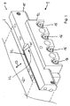
- the device 1 has a basic body 2 indicated only schematically.
- the device 1 can be positioned on a frame, not shown, in a desired installation position, so that a substrate such as a book on the device 1 can be passed so that discharged fluid is applied to the substrate.
- a valve assembly for releasing or interrupting supplied fluid, control devices, heaters, in the case of pneumatic valves pneumatic connections and channels or in the case of an electric valve drive means electrical connections and Holding devices may be provided.
- a fluid supply channel may be formed in the main body 2 for supplying fluid.
- the device 1 furthermore has a nozzle arrangement 4 detachably fastened to the base body 2.
- the nozzle arrangement 4 has a first nozzle part 6 firmly screwed to the base body 2.
- the function of the main body 2 and the nozzle part 6 can also be summarized in one part.
- the nozzle part 6 has a fluid supply passage 8 communicating with a fluid supply passage (not shown) formed in the main body 2. Through the Fluidzu Glasskanal 8, the fluid can be introduced into the nozzle assembly 4. It is designed as a through hole and in the partial sectional view according to FIG. 6 also recognizable.
- the nozzle arrangement 4 furthermore has a further nozzle part 10 which is movable relative to the first nozzle part 6 and which is fastened by means of a clamping piece 12 to the stationary nozzle part 6 in such a way that it is oriented in the direction of an arrow 14 (FIG. FIG. 2 ) is moved back and forth and furthermore not lost, regardless of the respective installation position of the device 1.
- the clamping piece 12 is secured with a plurality of screws 16 on the nozzle part 6.
- the clamping piece 12 has a substantially rectangular shape in cross-section and is in the region of a corner with a recess 16 (FIG. FIG. 3 ), which is bounded by a plurality of flat surfaces. On a surface formed on a projection 18, the clamping piece 12 is in contact with the movable nozzle part 10.
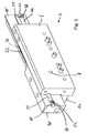
- the nozzle assembly 4 comprises an elongate fluid-feedable slot 20 (FIG. FIG. 2 ) with an outlet opening 22 for dispensing fluid.
- the length of the slot 20, that is, the extent in the direction of the double arrow 14 is variable.
- Outlet opening 22 and substrate movement direction are in the embodiment substantially perpendicular to each other.
- the width of the slot is defined by the distance of the nozzle part 6 and the movable nozzle part 10 in the region of the slot 20.
- the slot 20 is formed between the nozzle parts 6, 10, that correspondingly shaped recesses 24, 26, in particular recesses in the opposite surfaces of the nozzle parts 6, 10 are formed.
- the recess 24 in the movable nozzle member 10 and the slot 20 are respectively in the illustrations in FIG. 6a . b, c recognizable.
- a recess 26 is formed, such as in FIG. 2 is recognizable.
- the slot 20 is bounded by the lateral boundaries of the recesses 24, 26, in FIG. 2 represented by the reference numerals 28, 30, which are also in the FIGS. 6 are shown. Due to the distance of the lateral boundaries 28, 30 in the direction of the longitudinal extension of the slot 20 and thus also in the direction of the double arrow 14, the length of the slot L and the length of the outlet opening 22 is fixed.
- the spindle device has a threaded spindle rotatably mounted on a section of the base body 2 in a bore and an internal thread 13 arranged on the nozzle part 10, with which the external thread of the threaded spindle engages in such a way that the nozzle part 10 is moved axially in the direction of rotation by the threaded spindle Double arrow 14 is reciprocable.
- the equalizing channel 32 is formed inside the nozzle assembly 4.
- the compensation channel 32 is designed in the embodiment substantially cylindrical and formed by the fact that in the fixed nozzle member 6 a semi-circular in cross section recess 34 is milled and in the movable nozzle member 10 is formed in cross-section also a semi-circular recess 36 so that a total of substantially in cross-section semicircular or alternatively part-cylindrical compensating channel 32 is formed.
- the nozzle assembly 4 further comprises a cross-distribution channel 38, which is formed substantially as a part-circular channel. is formed and extends in the direction of the double arrow 14 and thus in the direction of the longitudinal extent of the slot 20.
- the distribution channel 38 communicates with the slot 22, so that fluid evenly from the outlet opening 22 of the slot 20th can escape.
- the distribution channel 38 in turn is in fluid communication with the compensation channel 32 and thus the supply channel 8 and thus the fluid source.
- the fluid connection between distribution channel 38 and compensation channel 32 is realized in the embodiment by a connecting channel 40 (see FIG. 6 ), which communicates on the one hand with a portion of the compensation channel 32 and on the other hand with a portion of the distribution channel 38.
- the connecting channel 40 is formed in the form of a depression in the movable nozzle part 10. However, it could equally be formed as a recess in the fixed part or in the fixed part 6 and the movable nozzle part 10.
- the volume for receiving fluid in the compensation channel 32 is variable.
- a displacement body 42 is arranged in the form of a piston 44 movable within the compensation channel 32.
- a seal for example as an O-ring seal 46 (FIG. FIG. 6 ), be provided.
- the displacement body 42 designed as a piston 44 is in the exemplary embodiment with its portion lying outside of the compensation channel 42, in particular with its end portion, the in FIG. 5 is shown by means of a screw 48 which is inserted through a bore 50, coupled to the movable nozzle member 10 in which a threaded bore for receiving the screw 48 is formed.
- a closure body 54 in the form of a piston 56 is formed, whose end portion is also a sealing element in the form of an O-ring 58 is arranged so that the piston 56 is disposed sealed within the transverse distribution channel 38. Due to the movable and at the same time sealed arrangement, the fluid-filled effective length of the distribution channel 38 is variable. This is the same time effective length of the slot 20 changeable. As I said, different lengths are already in the FIGS. 6a to c shown.
- FIG. 5 well illustrated is a section, in particular an end section 60 (see FIG. 5 left) of the piston 56 is coupled to the movable nozzle part 10.
- a screw 62 is inserted with its external thread through a through hole 64 in the piston 56 and into an internal thread, which is formed in the nozzle part 10, screwed. This results in that the effective fluid-fillable length of the distribution channel 38 is always changed when the movable nozzle part 10 moves.
- the effective length and the volume of the distribution channel 38 are always changed during a movement of the movable nozzle part 10 to vary the length of the slot 20, and the effective fluid-fillable length and the volume of the compensation channel 32 are changed. Due to the dimensions of the distribution channel 38 and the compensation channel 32 and the dimensioning of the slot 20 is achieved that when changing the length of the distribution channel 38 by moving the movable nozzle member 10, the total volume of the distribution channel 38, the slot 20 and the compensation channel 32 is substantially constant remains. It follows that upon displacement of the nozzle member 10 neither fluid is pushed out of the outlet opening 22 nor air penetrates into the slot 20, depending on whether the effective length of the distribution channel 38 and thus the length of the slot 20 is increased or decreased.
- the shape of the compensation channel 32 and / or the shape of the distribution channel 38 may also not be semicircular, for example polygonal, such as rectangular, square, polygonal, elliptical, circular or the like.
- shape of the displacement body 42 and the piston 44 and the shape of the closure body 54 and the piston 56 would be adapted.
- compensation channel 32 and distribution channel 38 are arranged substantially parallel to each other in the embodiment. In principle, it is also conceivable that a non-parallel arrangement exists.
- the fluid will flow through the device 1 as follows. Fluid is introduced into the nozzle arrangement 4 through a feed channel 8 and flows into the compensation channel 32. From the compensation channel 32, the fluid flows through the connecting channel 40 ( FIG. 6 ). The fluid passes from the connection channel 40 into the transverse distribution channel 38 and flows from it through the slot 20 and is discharged through the outlet opening 22 of the device 1 and applied to a substrate.
- the flowed and effective length of both the compensation channel 32, and the cross-distribution channel 38 is variable.
- the effective length is determined by the respective position of the closure body 54 in the distribution channel 38 or by the position of the displacement body 42 in the compensation channel 32
- FIG. 6a the length of the compensation channel 32 is relatively small and the length of the distribution channel 38 and the length of the slot 20 is large.
- middle lengths of the compensation channel 32 and the distribution channel 38 are shown.
- the length of the compensation channel 32 is relatively large and the length of the distribution channel 38 and the length of the slot 20 is relatively small. This is due to the respective position of the movable nozzle part 10.
- the nozzle assembly 4 on a tear-off edge 70 which is formed by a recess 72 on the movable nozzle member 10.
- the fluid-coated substrate which is in FIG. 3 moved from left to right, out of contact from the surface of the nozzle assembly, in particular the nozzle part 10. The fluid dissolves well and remains on the substrate.
- All the following exemplary embodiments have in common that a volume compensation is present. This means that when changing the effective length of the outlet opening 22 of a variable length slot 20 by means of a compensation volume or a compensation channel 32, the entire volume of the slot 20, a communicating with this transverse distribution channel 38 and one with the distribution channel 38 and / or the slot 20 communicating compensation channel 32 in the case of a variation of the length can be kept substantially constant. In any case, all embodiments have a compensation volume or a compensation channel 32, whose fluid-fillable volume is variable and which communicates with the distribution channel 38.
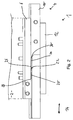
- FIGS. 7 and 8 shown alternative embodiment of a device 1 for dispensing fluid has similar components and functionalities as the embodiment described above; In this regard, like reference numerals have been used and reference is made to the above descriptions in their entirety. In the following, differences of the alternative embodiments will be described essentially.
- a feed channel 8 is formed, which communicates with a fluid source.
- the fluid supply channel 8 communicates on the one hand with a compensation channel 32 and on the other hand with a formed in the body connecting channel 40, which is in fluid communication with a transverse distribution channel 38.
- the distribution channel 38 communicates with a slot 20, which has a slot-shaped outlet opening 22, through which fluid can be discharged.
- the effective fluid-fillable length of the distribution channel 38 and the slot 20 can be varied in that a piston 58, which is movable and sealed in the direction of its longitudinal axis, forms a closure body 56 and is movably arranged. At the end of the piston 58, a flag 57 is formed, which limits the slot 20 laterally.
- the piston 58 can be reciprocated to vary the length of the slot 20.
- the volume of the compensation channel 32 can also be changed.
- a displacement body 42 is sealed in the distribution channel 32 in the form of a piston 44 and arranged movable.
- the piston 44 can be reciprocated in the direction of the arrow 14 and thus its longitudinal axis.
- FIGS. 7 and 8 shown device may be designed so that a fluid supply channel 8 is formed in the base body 2, which flows through an annular space 32 ', which forms a compensation channel and whose volume is variable.
- a displacement body 42 in the form of a piston 44th within the compensation channel 32 'movably arranged to change the volume can.
- the annular compensation passage 32 ' communicates with a connection passage 40, which in turn communicates fluidly with a distribution passage 38 as previously described.
- a difference from the embodiment described above is essentially that in a formed in a base body 2 compensation channel 32 designed as a pipe displacement body 42 and piston 44 is arranged longitudinally displaceable movable in the direction of the double arrow 14, so that the volume of the Equalization channel 32 can be varied.
- the supply of the fluid from the fluid source takes place through the inner cavity 43 of the tubular piston 4, the upper end of which may be connected to a hose, for example.
- the fluid can continue the compensation channel 32 in FIG. 9 flow down and flow through a connecting channel 40, to then flow into the transverse distribution channel 38, which communicates with the slot 20.
- the distribution channel 38 is in turn, as previously, in particular with reference to the embodiment according to FIG. 7 described in its effective length variable to vary the length of the slot 20 can.
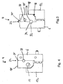
- the device 1 for dispensing fluid also has a main body 2.
- a compensation channel 32 which is designed as an annular channel in the base body 2
- fluid can be introduced from a supply channel.
- a tubular displacer is movably disposed within the equalization channel 32.
- a sealed piston 44 is provided, which closes the inner cavity 43 of the tube.
- a plurality of distributed over the circumference passageways 82 are formed in the tubular displacement body 42 through which fluid from the interior space 43 can flow into the compensation channel 32.
- the fluid may also flow through a communicating in the upper portion with the compensation channel 32 connecting channel 40 from the compensation channel 32 in the transverse distribution channel 38 and from there in the manner previously described in the slot 20th
- fluid is supplied through an annular compensation channel 32 from a feed channel of the device 1.
- the substantially cylindrical piston 44 is sealed and movably movable within the compensation channel 32 in the direction of the double arrow 14.
- a plurality of passageways 82 are preferably formed, can flow through the fluid from the compensation channel 32 in a distribution channel 38, which is also designed as an annular channel and communicates with a slot 20 having an outlet opening 22.
- a piston rod 47 is sealed performed by a portion 49 of the body and serves to support the piston 44th
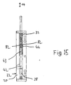
- FIG. 15 shows another alternative embodiment.
- fluid flows from above into an annular compensation channel 32.
- a substantially cylindrical piston 44 is sealingly disposed within the compensation channel 32 movable in the direction of the double arrow 14.
- a plurality of obliquely extending with respect to the longitudinal axis of the piston passageways 82 are formed, through which fluid from the outlet channel 32 can flow into an inner cavity 43.
- This is formed in a tubular portion.
- the cavity 43 opens into a transverse distribution channel 38, which is delimited by the tubular portion of the closure body 42 and opens into the slot 20 with outlet opening 22.
Description
Die vorliegende Erfindung betrifft eine Vorrichtung zum Abgeben von Fluid auf ein Substrat, mit einem Grundkörper, einem mit einer Fluidquelle verbindbaren Fluidzuführkanal zum Zuführen des Fluids, und einer Düsenanordnung, welche einen mit dem Fluidzuführkanal kommunizierenden Verteilerkanal aufweist und welche einen mit dem Verteilerkanal kommunizierenden im Wesentlichen länglichen Schlitz mit mindestens einer Austrittsöffnung zum Abgeben des Fluids aufweist, wobei die mit Fluid füllbare wirksame Länge des Verteilerkanals mittels eines in dem Verteilerkanal bewegbaren Verschlusskörpers variierbar ist.The present invention relates to a device for dispensing fluid onto a substrate, comprising a base body, a fluid supply channel connectable to a fluid source for supplying the fluid, and a nozzle assembly having a distribution channel communicating with the fluid supply channel and having a substantially communicating with the distribution channel elongated slot having at least one outlet opening for discharging the fluid, wherein the fluid fillable effective length of the distribution channel is variable by means of a movable in the distribution channel closure body.
Derartige Vorrichtungen zum Abgeben von Fluid, die auch als Auftragskopf bezeichnet werden, kommen in verschiedenen industriellen Bereichen zum Einsatz, um Klebstoffe, Dichtstoffe oder andere Flüssigkeiten auf verschiedene Substrate wie Folien, Verpackungsmaterialien, Teile von Maschinen oder andere Werkstücke flächig aufzutragen. Auch kommen solche Vorrichtungen zum Einsatz, um Buchrücken zu beleimen. Die Vorrichtung wird an einem Rahmengestell oder dergleichen so montiert, dass das zu beschichtende Substrat vorbeigeführt wird, während das Fluid abgegeben wird. So wird das Fluid auf das Substrat aufgetragen. Dabei strömt das Fluid aus der schlitzförmigen länglichen Austrittsöffnung heraus und gelangt auf die Oberfläche des Substrates, beispielsweise eines Buchrückens. Die Austrittsöffnung des länglichen Schlitzes der Schlitzdüsenanordnung kann entweder durchgängig sein, um einen durchgehenden Streifen von Fluid aufzutragen, oder aber so unterteilt sein, dass mehrere benachbarte Streifen oder dünne Fäden oder Raupen abgegeben und aufgetragen werden.Such fluid dispensers, also referred to as applicator heads, are used in a variety of industrial applications to apply adhesives, sealants, or other liquids over a variety of substrates such as films, packaging materials, machine parts, or other workpieces. Also, such devices are used to glue book spines. The device is mounted on a rack or the like so that the substrate to be coated is passed while the fluid is dispensed. So the fluid is applied to the substrate. In this case, the fluid flows out of the slot-shaped elongated outlet opening and reaches the surface of the substrate, for example a book spine. The outlet opening of the elongate slot of the slot nozzle assembly may be either continuous to apply a continuous strip of fluid or may be divided so as to dispense and apply a plurality of adjacent strips or thin threads or beads.
Zur Variation der wirksamen Länge der im Wesentlichen schlitzförmigen Austrittsöffnung der Düsenanordnung kann die wirksame mit Fluid befüllbare Länge des Quer-Verteilerkanals variiert werden. Zu diesem Zweck ist an mindestens einer Seite des Verteilerkanals ein kolbenartiger Verschlusskörper bewegbar innerhalb des Verteilerkanals angeordnet. Der Verschlusskörper ist abgedichtet innerhalb des Verteilerkanals angeordnet, so dass er den Verteilerkanal seitlich in unterschiedlichen Positionen so begrenzt, dass die wirksame Länge des Verteilerkanals und damit die wirksame Länge des Schlitzes und damit der schlitzförmigen Austrittsöffnung variierbar ist. Der Verschlusskörper kann beispielsweise mit einer Stange verbunden sein, die manuell oder motorisch oder mithilfe einer Gewindespindeleinrichtung hin- und herverfahrbar ist. Auf diese Weise lassen sich unterschiedlich breite Fluidstreifen abgeben und auf ein Substrat auftragen. So kann beispielsweise bei der Buchrückenbeleimung die Auftragsbreite an die Größe der Bücher angepasst werden. Eine solche Vorrichtung ist beispielsweise aus der
Bei der Variation der Länge des Verteilerkanales durch Verschieben eines Verschlusskörpers ändert sich das Volumen des Verteilerkanals und in solchen Fällen, in denen der Verschlusskörper mit einer Art Fahne, die in den Schlitz bis in den Bereich der Austrittsöffnung hineinragt verbunden ist, das Volumen des Verteilerkanals und des Schlitzes. Diese Änderung des Volumens kann bei der Variation der Länge zu Nachteilen führen. Während einer Verkleinerung der Auftragsbreite durch Verkürzung des Verteilerkanals kann Klebstoff aus der schlitzförmigen Austrittsöffnung herausgedrückt werden, so dass der Klebstoff in unerwünschter Weise auf das Substrat oder die Umgebung gelangt. Beim Vergrößern des Volumens des Verteilerkanals und ggf. des Schlitzes kann Luft aus der Umgebung in den Schlitz und den Verteilerkanal hineinströmen, während das Volumen des Verteilerkanals sich vergrößert. Das Hineinsaugen von Luft kann dann bei Wiederaufnahme des Auftragsbetriebes dazu führen, dass unmittelbar nach dem Öffnen eines Auftragsventiles noch kein Klebstoff aus der Austrittsöffnung herausströmt, so dass das Substrat nicht oder nur unvollständig mit Klebstoff versehen wird. Dies kann dazu führen, dass beispielsweise ein Buchrücken unvollständig beleimt und deshalb anschließend nicht weiter verarbeitet werden kann.When varying the length of the distribution channel by moving a closure body, the volume of the distribution channel and in such cases in which the closure body is connected with a kind of flag, which protrudes into the slot into the region of the outlet opening, the volume of the distribution channel and of the slot. This change in volume can lead to disadvantages in varying the length. During a reduction of the application width by shortening the distribution channel adhesive can be pushed out of the slot-shaped outlet opening, so that the adhesive undesirably reaches the substrate or the environment. When increasing the volume of the distribution channel and possibly the slot, air from the environment can flow into the slot and the distribution channel as the volume of the distribution channel increases. The sucking in of air can then lead to a resumption of the job operation that immediately after the opening of a job valve no adhesive flows out of the outlet opening, so that the substrate is not or only partially provided with adhesive. This can mean that, for example, a book spine incompletely glued and therefore subsequently can not be further processed.
Aufgabe der vorliegenden Erfindung ist es daher, eine Vorrichtung zum Abgeben von Fluid auf ein Substrat bereitzustellen, bei der die Veränderung der wirksamen Länge des Schlitzes nicht zu den zuvor beschriebenen Nachteilen führt. Insbesondere soll eine Vorrichtung zum Abgeben von Fluid bereitgestellt werden, die auch nach Änderung der Schlitzlänge und damit Auftragsbreite sofort optimale Beschichtungsergebnisse erzielt.The object of the present invention is therefore to provide a device for dispensing fluid onto a substrate, wherein the change in the effective length of the slot does not lead to the disadvantages described above. In particular, a device for dispensing fluid is to be provided which immediately achieves optimum coating results even after changing the slot length and thus application width.
Die Erfindung löst die Aufgabe bei einer Vorrichtung der eingangs genannten Art dadurch, dass ein Ausgleichskanal mit den im kennzeichnenden Teil genannten Merkmalen mit dem Verteilerkanal in Fluidverbindung steht, dessen Volumen zur Aufnahme von Fluid veränderbar ist.The invention solves the problem in a device of the type mentioned in that a compensation channel with the features mentioned in the characterizing part is in fluid communication with the distribution channel, whose volume is variable for receiving fluid.
Durch den erfindungsgemäßen Ausgleichskanal, welcher in Fluidverbindung mit dem Verteilerkanal steht und dessen inneres Volumen, welches für eine Aufnahme von Fluid bereitsteht, veränderbar ist, lässt sich in vorteilhafter Weise ein Volumenausgleich oder eine Volumenkompensation verwirklichen, insbesondere dergestalt dass bei einer Verkürzung der Länge des Verteilerkanals durch Einschieben des Verschlusskörpers gleichzeitig das Volumen des erfindungsgemäßen Ausgleichskanals vergrößert wird, und bei einer Vergrößerung des Verteilerkanals durch entsprechende Verschiebung des Verschlusskörpers das Volumen des Ausgleichskanals verkleinert wird. Dadurch lässt sich erreichen, dass bei einer Verschiebung des Verschlusskörpers zur Variation der Länge des Verteilerkanals und damit der Länge des Schlitzes weder Fluid während der Längenverstellung aus der Austrittsöffnung herausgedrückt wird, noch bei einer Vergrößerung der Länge Gas in den Schlitz und den Verteilerkanal hinein gesaugt wird. Mittels des Ausgleichkanals lassen sich innere Volumenänderungen des Verteilerkanals und ggf. auch des Schlitzes kompensieren. Bei einer Variation der Schlitzlänge und damit der Auftragsbereite kommt es somit weder zu unerwünschten Verschmutzungen der äußeren Oberflächen der Schlitzdüsenanordnung oder der Umgebung der Vorrichtung, noch zu schlechten Beschichtungsergebnissen beim erneuten Einschalten des Auftragsvorganges. Erfindungsgemäß lässt sich somit erreichen, dass kein Produktausschuss aufgrund der Längenänderung des Schlitzes erfolgt. Zu diesem Zweck ist das Volumen des Ausgleichskanals veränderbar.By means of the compensation channel according to the invention, which is in fluid communication with the distributor channel and whose internal volume is ready for receiving fluid, can be advantageously realized a volume compensation or volume compensation, in particular such that at a shortening of the length of the distribution channel by inserting the closure body at the same time the volume of the compensation channel according to the invention is increased, and at an enlargement of the distribution channel by corresponding displacement of the closure body, the volume of the compensation channel is reduced. As a result, when the closure body is displaced to vary the length of the distribution channel and thus the length of the slot, neither fluid is forced out of the exit opening during the length adjustment, nor is gas sucked into the slot and the distribution channel as the length increases , By means of the compensation channel can be compensated internal volume changes of the distribution channel and possibly also of the slot. With a variation of the slot length and thus the order ready thus it comes to neither undesirable contamination of the outer surfaces of the slot nozzle assembly or the environment of the device, nor to poor coating results when switching the order process again. According to the invention can thus achieve that no product broke due to the change in length of the slot. For this purpose, the volume of the compensation channel is changeable.
Erfindungsgemäß ist das Volumen des Ausgleichskanals in Abhängigkeit von der Größe des jeweils wirksamen mit Fluid befüllten Volumens des Verteilerkanals veränderbar derart, dass bei einer Verstellung der wirksamen Länge des Verteilerkanals das gesamte mit Fluid gefüllte Volumen des Verteilerkanals, des Ausgleichkanals und des Schlitzes im Wesentlichen konstant bleibt. Auf diese Weise wird das Volumen wesentlicher inneren Strömungskanäle der Düsenanordnung im Wesentlichen konstant gehalten, so dass es bei einer Vergrößerung der Länge nicht zu einem Eintreten von Luft in die inneren Strömungskanäle kommt und bei einer Verkleinerung der Länge des Schlitzes nicht zu einem unerwünschten Herausdrücken oder Herausströmen von Klebstoff aus der Austrittsöffnung kommt. Anders ausgedrückt wird durch die Erfindung erreicht, dass in dem Maße, in dem das Volumen des Verteilerkanals und des Schlitzes bis zur Austrittsöffnung sich ändert, gleichermaßen das Volumen des Ausgleichskanals geändert wird. Auf diese Weise kommt es sehr genau zu der erfindungsgemäßen Volumenkompensation und einer Vermeidung der im Stand der Technik vorhandenen Nachteile.According to the invention, the volume of the compensation channel is variable in dependence on the size of the respectively effective fluid-filled volume of the distributor channel, such that when the effective length of the distributor channel is adjusted, the entire volume of the distributor channel, the compensation channel and the slot filled with fluid substantially remains constant. In this way, the volume of essential inner flow channels of the nozzle assembly is kept substantially constant, so that it does not come with an increase in length to an entry of air into the inner flow channels and at a reduction of the length of the slot does not lead to an undesired extrusion or outflow of adhesive comes out of the outlet. In other words, it is achieved by the invention that, as the volume of the distribution channel and the slot changes up to the exit opening, the volume of the compensation channel is likewise changed. In this way it comes very precisely to the volume compensation according to the invention and to avoid the disadvantages present in the prior art.
Gemäß einer bevorzugten Ausführungsform wird ferner vorgeschlagen, dass das Volumen des Ausgleichskanals dadurch veränderbar ist, das ein Verdrängungskörper bewegbar innerhalb des Ausgleichskanals angeordnet ist. Durch einen innerhalb des Ausgleichskanals bewegbaren Verdrängungskörper lässt sich das Volumen des Ausgleichkanals auf konstruktiv relativ einfache und gleichzeitig präzise Weise variieren, so dass die beschriebene Volumenkompensation sehr genau erfolgen kann.According to a preferred embodiment, it is further proposed that the volume of the compensation channel can be changed by a displacement body being arranged movably within the compensation channel. By means of a displacement body which can be moved within the compensation channel, the volume of the compensation channel can be varied in a structurally relatively simple and at the same time precise manner, so that the described volume compensation can take place very precisely.
Besonders bevorzugt ist es, dass der Verdrängungskörper ein Kolben ist, der abgedichtet und bewegbar innerhalb des Ausgleichskanals angeordnet ist. Ein solcher Kolben kann entweder metallisch dichtend innerhalb des Ausgleichskanals angeordnet sein oder aber eventuell auch durch mindestens ein zusätzliches Dichtungselement, etwa einem Kolbenring oder dergleichen abgedichtet werden. Auch lässt ich ein derartiger Kolben vergleichsweise einfach und genau herstellen. Desweiteren kann ein solcher Kolben, insbesondere wenn er aus Metall besteht und auch der Ausgleichskanal innerhalb eines metallischem Bauteils ausgebildet ist besonders temperaturbeständig sein.It is particularly preferred that the displacement body is a piston which is arranged sealed and movable within the compensation channel. Such a piston can be arranged either metallic sealing within the compensation channel or possibly also be sealed by at least one additional sealing element, such as a piston ring or the like. Also, I can make such a piston relatively easy and accurate. Furthermore, such a piston, in particular if it is made of metal and also the compensation channel is formed within a metallic component is particularly temperature resistant.
Besonders bevorzugt ist es, dass der Ausgleichskanal eine im Wesentlichen zylindrische, teilzylindrische oder im Wesentlichen mehreckige Form hat und durch einen im Wesentlichen zylindrischen, teilzylindrischen oder mehreckigen Kolben abgedichtet wird. Auf diese Weise ergeben sich herstellungstechnische und funktionale Vorteile. Desweiteren kann die gewünschte Volumenkompensation präzise erreicht und genau vorausberechnet werden.It is particularly preferred that the compensation channel has a substantially cylindrical, partially cylindrical or substantially polygonal shape and is sealed by a substantially cylindrical, partially cylindrical or polygonal piston. This results in manufacturing and functional advantages. Furthermore, the desired volume compensation can be precisely achieved and accurately calculated in advance.
Gemäß einer alternativen bevorzugten Ausführungsform ist vorgesehen, dass der in dem Verteilerkanal bewegbare Verschlusskörper ein Kolben ist, der den Verteilerkanal seitlich abdichtet und dadurch die wirksame Länge des Verteilerkanals begrenzt. Die oben im Zusammenhang mit dem Verdrängungskörper des Ausgleichskanals beschriebenen Vorteile ergeben sich auch dann, wenn der innerhalb des Verteilerkanals bewegbare Verschlusskörper zur Variation der wirksamen Länge ein Kolben ist.According to an alternative preferred embodiment, it is provided that the closure body which can be moved in the distributor channel is a piston which laterally seals the distributor channel seals and thereby limits the effective length of the distribution channel. The advantages described above in connection with the displacement body of the compensation channel also arise when the closure body which can be moved within the distributor channel is a piston for varying the effective length.
Gemäß einer bevorzugten Weiterbildung wird vorgeschlagen, dass der Verteilerkanal und der Ausgleichskanal im Wesentlichen parallel zueinander angeordnet sind Durch die parallele Anordnung von einem im Wesentlichen länglichen, gerade verlaufenden Verteilerkanal und einem im Wesentlichen länglichen, gerade verlaufenden Ausgangskanal ergeben sich weitere herstellungstechnische Vorteile. Ferner lassen sich eine kompakte Bauform und ein günstiger Fluidfluss realisieren.According to a preferred embodiment, it is proposed that the distribution channel and the compensation channel are arranged substantially parallel to each other by the parallel arrangement of a substantially elongated, straight distribution channel and a substantially elongated, straight output channel resulting in further manufacturing advantages. Furthermore, a compact design and a favorable fluid flow can be realized.
Zweckmäßigerweise kommunizieren Verteilerkanal und Ausgleichskanal mittels eines Verbindungskanals miteinander. Dabei ist es besonders bevorzugt, dass der Ausgleichskanal so in Bezug zu dem Zuführkanal und dem Verteilerkanal angeordnet ist, dass das Fluid im Betrieb von dem Zuführkanal in den Ausgleichskanal strömt, den Ausgleichskanal durchströmt, dann den Verbindungskanal zwischen Ausgleichskanal und Verteilerkanal (38) durchströmt und dann den Verteilerkanal und den Schlitz durchströmt, da auf diese Weise Toträume über den gesamten Einstellbereich der Auftragsbreite für das Fluid weitgehend vermieden werden können, in denen z. B. der Kleber nicht ausgetauscht wird, da das Fluid jegliche Hohlräume auf dem Weg zur Austrittsöffnung durchströmt. Unerwünschte Vercrackungen oder Aushärtungen des Fluides und Lufteinschlüsse können somit weitgehend vermieden werden.Appropriately communicate distribution channel and compensation channel by means of a connection channel with each other. It is particularly preferred that the compensation channel is arranged in relation to the supply channel and the distribution channel, that the fluid flows from the supply channel into the compensation channel during operation, flows through the compensation channel, then flows through the connection channel between the compensation channel and distribution channel (38) and then flows through the distribution channel and the slot, since in this way dead spaces over the entire adjustment range of the application width for the fluid can be largely avoided, in which z. B. the adhesive is not replaced, since the fluid flows through any cavities on the way to the outlet opening. Unwanted cracks or hardening of the fluid and air pockets can thus be largely avoided.
Bei einer besonders bevorzugten weiteren Ausführungsform ist vorgesehen, dass die Vorrichtung zwei relativ zueinander in Längsrichtung des Schlitzes bewegbare Düsenteile aufweist, dass der Schlitz seitlich durch die zwei Düsenteile begrenzt wird und die wirksame Länge des Schlitzes durch Verschiebung der beiden Düsenteile relativ zueinander verändert wird. Dadurch, dass zwei relativ zueinander bewegbare Düsenteile vorgesehen sind und sich durch entsprechende Relativverschiebung der Düsenteile zueinander die Länge des Schlitzes verändert, lässt sich eine kompakte Bauform erzielen. Auch die Anzahl der beweglichen Teile ist hierbei reduziert.In a particularly preferred further embodiment, it is provided that the device has two nozzle parts which are movable relative to one another in the longitudinal direction of the slot, that the slot is delimited laterally by the two nozzle parts and the effective length of the slot is changed by displacement of the two nozzle parts relative to each other. Characterized in that two relatively movable nozzle parts are provided and changed by appropriate relative displacement of the nozzle parts to each other, the length of the slot, a compact design can be achieved. The number of moving parts is reduced here.
Gemäß einer Weiterbildung wird vorgeschlagen, dass der Verteilerkanal und/oder Ausgleichskanal und/oder Verbindungskanal im Wesentlichen als Vertiefung in einem der beiden Düsenteile oder durch Vertiefungen in beiden Düsenteilen ausgebildet ist. Es lassen sich strömungsgünstige Verläufe und herstellungstechnische Vorteile realisieren. So können beispielsweise die Kanäle als Ausfräsungen in den Düsenteilen hergestellt werden.According to a further development, it is proposed that the distribution channel and / or compensation channel and / or connection channel is formed essentially as a depression in one of the two nozzle parts or by depressions in both nozzle parts. It Streamlined processes and manufacturing advantages can be realized. For example, the channels can be made as cutouts in the nozzle parts.
Bei einer weiteren bevorzugten Ausführungsform ist vorgesehen, dass der Kolben zur Begrenzung des Verteilerkanals und/oder der Kolben zur Veränderung des Volumens des Ausgleichskanals mechanisch mit dem bewegbaren Düsenteil gekoppelt ist, insbesondere mittels einer Kopplungsstange. Durch die Kopplung des Kolbens in dem Verteilerkanal und/oder des Kolbens in dem Ausgleichkanal mit dem bewegbaren Düsenteil lässt sich eine einfache automatische Volumenkompensation erreichen. Bei Bewegung des Düsenteils zur Veränderung der Länge des Schlitzes wird automatisch das Volumen des Ausgleichskanals angepasst. Hierzu wird insbesondere eine einfache Kopplungs- oder Kolben-Stange eingesetzt. Wird beispielsweise das bewegliche Düsenteil zur Verkleinerung der Schlitzlänge bewegt, kann gleichzeitig das Volumen des Ausgleichskanals vergrößert werden durch entsprechende Verstellung des Kolbens. Die Bewegung der beiden Düsenteile relativ zueinander kann mittels einer mechanischen oder motorischen Einrichtung, insbesondere einer Gewindespindel oder auch mithilfe eines Motors, insbesondere eines Elektromotors vorgenommen werden.In a further preferred embodiment it is provided that the piston for limiting the distributor channel and / or the piston for changing the volume of the compensation channel is mechanically coupled to the movable nozzle part, in particular by means of a coupling rod. By coupling the piston in the distribution channel and / or the piston in the compensation channel with the movable nozzle part, a simple automatic volume compensation can be achieved. As the nozzle member moves to change the length of the slot, the volume of the equalization channel is automatically adjusted. For this purpose, in particular a simple coupling or piston rod is used. For example, if the movable nozzle member moves to reduce the slot length, the volume of the compensation channel can be increased simultaneously by appropriate adjustment of the piston. The movement of the two nozzle parts relative to one another can be carried out by means of a mechanical or motor device, in particular a threaded spindle or else by means of a motor, in particular an electric motor.
Gemäß weiterer alternativer Ausführungsformen wird vorgeschlagen, der Kolben zur Veränderung des Volumens des Ausgleichskanals mindestens eine Durchgangsbohrung aufweist, durch welche das Fluid hindurch strömen kann. Ist in dem Kolben eine Durchgangsbohrung vorhanden, lässt sich das Fluid auf einfache Weise von dem Zuführkanal durch eine oder mehrere Durchgangsbohrungen in dem Kolben in den Ausgleichskanal einleiten. Der Kolben ist insbesondere als Rohr ausgebildet, welches einen solchen Außendurchmesser aufweist, dass das Rohr außen im Wesentlichen metallisch abgedichtet innerhalb des entsprechend geformten Ausgleichskanals bewegbar angeordnet ist, so dass das Fluid gleichzeitig durch das Innere des Rohres von dem Zuführkanal in den Ausgleichskanal einströmen kann, um von dort weiter, insbesondere durch einen Verbindungskanal in den Verteilerkanal eingeleitet zu werden. Ein solcher rohrartiger Kolben, der den Verdrängungskörper in dem Ausgleichskanal bildet, lässt sich einfach Herstellen, und das Fluid lässt sich in vorteilhafter Weise zuführen.According to further alternative embodiments, it is proposed that the piston for changing the volume of the compensation channel has at least one through-hole through which the fluid can flow. If a through-bore exists in the piston, the fluid can be easily introduced from the supply channel through one or more through-holes in the piston into the compensation channel. The piston is in particular designed as a tube which has an outer diameter such that the tube is arranged outside substantially metallically sealed within the correspondingly shaped compensation channel, so that the fluid can simultaneously flow through the inside of the tube from the supply channel into the compensation channel, to be further introduced from there, in particular by a connecting channel in the distribution channel. Such a tube-like piston, which forms the displacement body in the compensation channel, can be easily manufactured, and the fluid can be fed in an advantageous manner.
Bei einer alternativen Ausführungsform kann desweiteren vorgesehen sein, dass der Kolben mehrere Durchtrittskanäle aufweist, durch welche Fluid von dem Ausgleichskanal in den Verteilerkanal strömen kann. Der Kolben ist dabei außen abgedichtet innerhalb des Ausgleichskanals bewegbar. Die eine Seite des Ausgleichskanals steht in Fluidverbindung mit dem Zuführkanal. Bei Verschiebung des Kolbens wird gleichzeitig das Volumen des Ausgleichskanals vergrößert und das Volumen des Verteilerkanals und dessen Länge verkleinert. Ausgleichskanal und Verteilerkanal sind hierbei insbesondere fluchtend und koaxial und benachbart zueinander angeordnet. Der Kolben trennt Ausgleichskanal und Verteilerkanal voneinander, und durch Verstellung des Kolbens variiert das Volumen des Ausgleichskanals und des Verteilerkanals gleichzeitig.In an alternative embodiment may further be provided that the piston has a plurality of passageways through which fluid can flow from the compensation channel into the distribution channel. The piston is externally sealed inside the compensation channel movable. One side of the compensation channel is in fluid communication with the supply channel. When the piston is displaced, the volume of the compensation channel is simultaneously increased and the volume of the distributor channel and its length reduced. Compensation channel and distribution channel are in this case in particular aligned and coaxial and adjacent to each other. The piston separates the equalizing passage and the distributing passage, and by adjusting the piston, the volume of the equalizing passage and the distributing passage varies simultaneously.
Gemäß einer alternativen Ausführungsform wird vorgeschlagen, dass der Kolben einen ersten als Rohr ausgebildeten Abschnitt aufweist, durch welchen Fluid aus dem Fluidzuführkanal hindurch strömen kann, und einen abgedichtet in dem Ausgleichskanal angeordneten Dichtabschnitt aufweist, der das Rohr an einem Ende begrenzt, dass das Rohr mehrere Durchtrittsbohrungen aufweist, durch welche Fluid aus dem Rohr in den Ausgleichskanal und von dort durch den Verbindungskanal in den Verteilerkanal einströmen kann.According to an alternative embodiment, it is proposed that the piston has a first section formed as a tube, through which fluid can flow out of the fluid supply channel, and has a sealed in the compensation channel sealing portion which limits the tube at one end, that the tube more Having through-holes, through which fluid from the tube in the compensation channel and from there through the connecting channel can flow into the distribution channel.
Die Erfindung ist nachstehend anhand von mehreren bevorzugten Ausführungsbeispielen unter Bezugnahme auf die beiliegenden Zeichnungen beschrieben. Es zeigen:
Figur 1- eine Vorrichtung zum Abgeben von Fluid auf ein Substrat in einem ersten Ausführungsbeispiel in perspektivischer Darstellung;
Figur 2- die
Vorrichtung aus Figur 1 in einer Draufsicht, - Figur 3
- die
Vorrichtung aus Figur 1 in einer Ansicht von links, Figur 4- die
Vorrichtung aus Figur 1 in einer Ansicht von rechts, - Figur 5
- die
Vorrichtung aus Figur 1 in einer perspektivischen Ansicht von hinten; - Figur 6a
- die
Vorrichtung aus Figur 1 in Teilschnittdarstellung in einem Einstellzustand mit großer Schlitzlänge, - Figur 6b
- die
Vorrichtung aus Figur 1 in Teilschnittdarstellung in einem Einstellzustand mit mittlerer Schlitzlänge, - Figur 6c
- die
Vorrichtung aus Figur 1 in Teilschnittdarstellung in einem Einstellzustand mit kleinen Schlitzlänge, Figur 7- eine Vorrichtung zum Abgeben von Fluid in einem weiteren Ausführungsbeispiel in einer schematischen Darstellung,
Figur 8- die
Vorrichtung aus Figur 7 in einer Teilschnittdarstellung, Figur 9- eine Vorrichtung zum Abgeben von Fluid in einem weiteren Ausführungsbeispiel in einer schematischen Darstellung,
Figur 10- die
Vorrichtung aus Figur 9 in einer Teilschnittdarstellung, - Figur 11
- eine Vorrichtung zum Abgeben von Fluid in einem weiteren Ausführungsbeispiel in einer schematischen Darstellung,
Figur 12- die Vorrichtung aus
Figur 11 in einer Teilschnittdarstellung, Figur 13- eine Vorrichtung zum Abgeben von Fluid in einem weiteren Ausführungsbeispiel in einer schematischen Darstellung,
Figur 14- in einer Seitenansicht in Teilschnittdarstellung, und
- Figur 15
- eine Vorrichtung zum Abgeben von Fluid in einem weiteren Ausführungsbeispiel in einer schematischen Darstellung,
- FIG. 1
- a device for dispensing fluid onto a substrate in a first embodiment in perspective view;
- FIG. 2
- the device off
FIG. 1 in a plan view, - FIG. 3
- the device off
FIG. 1 in a view from the left, - FIG. 4
- the device off
FIG. 1 in a view from the right, - FIG. 5
- the device off
FIG. 1 in a perspective view from behind; - FIG. 6a
- the device off
FIG. 1 in partial section in a setting state with a large slot length, - FIG. 6b
- the device off
FIG. 1 in partial section in a setting state with average slot length, - FIG. 6c
- the device off
FIG. 1 in partial sectional view in a setting state with a small slot length, - FIG. 7
- a device for dispensing fluid in a further embodiment in a schematic representation,
- FIG. 8
- the device off
FIG. 7 in a partial sectional view, - FIG. 9
- a device for dispensing fluid in a further embodiment in a schematic representation,
- FIG. 10
- the device off
FIG. 9 in a partial sectional view, - FIG. 11
- a device for dispensing fluid in a further embodiment in a schematic representation,
- FIG. 12
- the device off
FIG. 11 in a partial sectional view, - FIG. 13
- a device for dispensing fluid in a further embodiment in a schematic representation,
- FIG. 14
- in a side view in partial section, and
- FIG. 15
- a device for dispensing fluid in a further embodiment in a schematic representation,
Die in den Figuren dargestellten Ausführungsbeispiele betreffen Vorrichtungen 1 zum Abgeben von Fluid auf ein Substrat, insbesondere auf ein relativ zu der Vorrichtung bewegbares Substrat. Es können verschiedene Fluide wie Klebstoffe, Heißschmelzklebstoff abgegeben und auf verschiedene Substrate wie Bücher, Buchrücken, Folien oder dergleichen aufgetragen werden. Insbesondere dienen die Vorrichtungen zum flächigen Beschichten von verschiedenen Substraten mit Klebstoff. Selbstverständlich können andere Fluide auf andere Substrate flächig oder in Streifenform oder in dünnen Fäden aufgetragen werden.The exemplary embodiments illustrated in the figures relate to
Wie insbesondere in
Die Vorrichtung 1 weist ferner eine an dem Grundkörper 2 lösbar befestigte Düsenanordnung 4 auf. Die Düsenanordnung 4 weist ein erstes fest mit dem Grundkörper 2 verschraubtes Düsenteil 6 auf. Die Funktion des Grundkörpers 2 und des Düsenteils 6 können auch in einem Teil zusammengefasst werden. Wie die Rückansicht gemäß
Die Düsenanordnung 4 weist ferner ein relativ zu dem ersten Düsenteil 6 bewegbares weiteres Düsenteil 10 auf, welches mittels eines Klemmstücks 12 so an dem feststehenden Düsenteil 6 befestigt ist, dass es in Richtung eines Pfeiles 14 (
Die Düsenanordnung 4 weist einen länglichen, mit Fluid speisbaren Schlitz 20 (
Durch relative Bewegung und Verschiebung des beweglichen Düsenteils 10 relativ zu dem feststehenden Düsenteil 6 lässt sich, wie insbesondere die
Wie gut in
Wie
ausgebildet ist und sich in Richtung des Doppelpfeils 14 und damit in Richtung der Längsausstreckung des Schlitzes 20 erstreckt. Der Verteilerkanal 38 kommuniziert mit dem Schlitz 22, so dass Fluid gleichmäßig aus der Austrittsöffnung 22 des Schlitzes 20 austreten kann. Der Verteilerkanal 38 steht seinerseits in Fluidverbindung mit dem Ausgleichskanal 32 und somit dem Zuführkanal 8 und somit der Fluidquelle. Die Fluidverbindung zwischen Verteilerkanal 38 und Ausgleichskanal 32 ist im Ausführungsbeispiel durch einen Verbindungskanal 40 verwirklicht (siehe
is formed and extends in the direction of the
Das Volumen zur Aufnahme von Fluid in dem Ausgleichskanal 32 ist veränderbar. Zu diesem Zweck ist ein Verdrängungskörper 42 in Form eines Kolbens 44 bewegbar innerhalb des Ausgleichskanals 32 angeordnet. Im Bereich des Endabschnitts des Kolbens 44 kann eine Dichtung, beispielsweise als O-Ringdichtung 46 (
Der als Kolben 44 ausgebildete Verdrängungskörper 42 ist im Ausführungsbeispiel mit seinem außerhalb des Ausgleichskanals 42 liegenden Abschnitt, insbesondere mit seinem Endabschnitt, der in
In dem Verteilerkanal 38 ist ein Verschlusskörper 54 in Form eines Kolbens 56 ausgebildet, dessen Endabschnitt ebenfalls ein Dichtelement in Form eines O-Rings 58 angeordnet ist, so dass der Kolben 56 abgedichtet innerhalb des Quer-Verteilerkanals 38 angeordnet ist. Durch die bewegliche und gleichzeitig abgedichtete Anordnung ist die mit Fluid befüllbare wirksame Länge des Verteilerkanals 38 veränderbar. Damit ist gleichzeitig die effektive Länge des Schlitzes 20 veränderbar. Wie gesagt, sind unterschiedlichen Längen bereits in den
Wie insbesondere
Gleichzeitig wird immer bei einer Bewegung des beweglichen Düsenteils 10 zur Variation der Länge des Schlitzes 20 einerseits die wirksame Länge und das Volumen des Verteilerkanals 38 verändert und die wirksame mit Fluid befüllbare Länge und das Volumen des Ausgleichskanals 32 verändert. Aufgrund der Dimensionierung des Verteilerkanals 38 und des Ausgleichskanals 32 und der Dimensionierung des Schlitzes 20 wird erreicht, dass bei Veränderung der Länge des Verteilerkanals 38 durch Bewegung des bewegbaren Düsenteils 10 das gesamte Volumen des Verteilerkanals 38, des Schlitzes 20 und des Ausgleichskanals 32 im Wesentlichen konstant bleibt. Hieraus folgt, dass bei einer Verschiebung des Düsenteils 10 weder Fluid aus der Austrittsöffnung 22 herausgedrückt wird noch Luft in den Schlitz 20 eindringt, je nachdem ob die wirksame Länge des Verteilerkanals 38 und damit die Länge des Schlitzes 20 vergrößert oder verkleinert wird.At the same time, the effective length and the volume of the
In nicht dargestellter Weise kann die Form des Ausgleichskanals 32 und/oder die Form des Verteilerkanals 38 auch nicht halbkreisförmig sein, beispielsweise mehreckig wie rechteckig, quadratisch, polygonal, elliptisch, kreisförmig oder dergleichen. Je nach Form würde die Form des Verdrängungskörpers 42 bzw. des Kolbens 44 und die Form des Verschlusskörpers 54 und des Kolbens 56 angepasst sein.In a manner not shown, the shape of the
Man erkennt deutlich, dass die der Ausgleichskanal 32 und Verteilerkanal 38 im Ausführungsbeispiel im Wesentlichen parallel zueinander angeordnet sind. Es ist prinzipiell alternativ auch denkbar, dass eine nicht parallele Anordnung besteht.It can be seen clearly that the
Im Betrieb wird das Fluid wie folgt die Vorrichtung 1 durchströmen. Durch einen Zuführkanal 8 wird Fluid in die Düsenanordnung 4 eingeleitet und strömt in den Ausgleichskanal 32 ein. Aus dem Ausgleichskanal 32 durchströmt das Fluid den Verbindungskanal 40 (
Wie insbesondere
Wie die
Anstelle der mechanischen Kopplung des Kolben 44, 56 zur gleichzeitigen Veränderung des Volumens des Ausgleichskanals 32 einerseits und des Volumens des Verteilerkanals 38 nebst Schlitz 20 andererseits können auch andere als mechanische Kopplungsmittel vorgesehen sein. So können beispielsweise motorisch angetriebene Antriebseinrichtungen vorgesehen sein, um die Kolben 44 bzw. 56 mithilfe einer Steuerungseinrichtung so zu steuern, dass die Summe der Volumina des Verteilerkanals 38 nebst Schlitz 20 und des Ausgleichskanals 32 im Wesentlichen konstant bleiben, wenn die Länge des Schlitzes 20 variiert wird.Instead of the mechanical coupling of the
Auch allen nachfolgenden Ausführungsbeispielen ist gemeinsam, dass eine Volumenkompensation vorhanden ist. Dies bedeutet, dass bei Veränderung der wirksamen Länge der Austrittsöffnung 22 eines längenveränderbaren Schlitzes 20 mittels eines Ausgleichsvolumens oder eines Ausgleichskanals 32 das gesamte Volumen des Schlitzes 20, eines mit diesem kommunizierenden Quer-Verteilerkanals 38 und eines mit dem Verteilerkanal 38 und/oder dem Schlitz 20 kommunizierenden Ausgleichskanals 32 im Falle einer Variation der Länge im Wesentlichen konstant gehalten werden kann. In jedem Fall weisen alle Ausführungsbeispiele ein Ausgleichsvolumen oder einen Ausgleichskanal 32 auf, dessen mit Fluid befüllbares Volumen veränderbar ist und der mit dem Verteilerkanal 38 kommuniziert.All the following exemplary embodiments have in common that a volume compensation is present. This means that when changing the effective length of the outlet opening 22 of a
Das in den
In einem Grundkörper 2 ist ein Zuführkanal 8 ausgebildet, der mit einer Fluidquelle kommuniziert. Der Fluid-Zuführkanal 8 kommuniziert einerseits mit einem Ausgleichskanal 32 und andererseits mit einem in dem Grundkörper ausgebildeten Verbindungskanal 40, welcher mit einem Quer-Verteilerkanal 38 in Fluidverbindung steht. Der Verteilerkanal 38 kommuniziert mit einem Schlitz 20, welcher eine schlitzförmige Austrittsöffnung 22 aufweist, durch welche Fluid abgegeben werden kann.In a
Die wirksame mit Fluid befüllbare Länge des Verteilerkanals 38 und des Schlitzes 20 lässt sich dadurch variieren, dass ein in Richtung seiner Längsachse beweglicher und abgedichteter Kolben 58, der einen Verschlusskörper 56 bildet und bewegbar angeordnet ist. Am Ende des Kolbens 58 ist eine Fahne 57 angeformt, die den Schlitz 20 seitlich begrenzt. Der Kolben 58 lässt sich hin- und herbewegen um die Länge des Schlitzes 20 zu variieren.The effective fluid-fillable length of the
Das Volumen des Ausgleichskanals 32 lässt sich ebenfalls verändern. Hierzu ist in dem Verteilerkanal 32 ein Verdrängungskörper 42 in Form eines Kolbens 44 abgedichtet und bewegbar angeordnet. Hierzu kann der Kolben 44 in Richtung des Pfeils 14 und somit seiner Längsachse hin- und herbewegt werden.The volume of the
Alternativ kann die in
Bei dem in
Auch hinsichtlich des in den
Bei dem in den
Schließlich zeigt
Claims (16)
- A device for dispensing fluid onto a substrate, with
a basic body (2),
a fluid supply duct (8), which can be connected to a fluid source, for supplying the fluid, and
a nozzle arrangement (4), which has a distributor duct (38) which communicates with the fluid supply duct (8), and which has a substantially elongate slot (20) with at least one exit opening (22) for dispensing the fluid, which slot communicates with the distributor duct (3 8),
the effective length of the distributor duct (38) which can be filled with fluid being variable by means of a closure body (54) which is movable in the distributor duct (38), characterised in that a compensation duct (32) is in fluid connection with the distributor duct (38), the volume of which for receiving fluid is changeable,
the volume of the compensation duct (32) being changeable dependent on the size of the effective fluid-filled volume in each case of the distributor duct (38), such that upon adjustment of the effective length of the distributor duct (38) the entire fluid-felled volume of the distributor duct (38), the compensation duct (32) and the slot (20) remains substantially constant. - A device according to Claim 1, characterised in that the volume of the compensation duct (32) is changeable by a displacement body (42) being arranged movably within the compensation duct (32).
- A device according to Claim 2, characterised in that the displacement body (42) is a piston (44) which is arranged in sealed and movable manner within the compensation duct (32).
- A device according to Claim 3, characterised in that the compensation duct (32) has a substantially cylindrical, partially cylindrical or substantially polygonal form and is sealed by a substantially cylindrical, partially cylindrical or polygonal piston (44).
- A device according to at least one of the above claims, characterised in that the closure body which is movable within the distributor duct (38) is a piston (56) which laterally seals the distributor duct (38) and thereby limits the effective length of the distributor duct (38).
- A device according to at least one of the above claims, characterised in that the distributor duct (38) and the compensation duct (32) are arranged substantially parallel to one another.
- A device according to at least one of the above claims, characterised in that the distributor duct (38) and the compensation duct (32) are in fluid connection with each other by means of a connecting duct (40).
- A device according to Claim 7, characterised in that the compensation duct (32) is arranged relative to the supply duct (8) and the distributor duct (38) such that the fluid during operation flows from the supply duct (8) into the compensation duct (32), flows through the compensation duct (32), then flows through the connecting duct (40) between the compensation duct (32) and distributor duct (38), and then flows through the distributor duct (38) and the slot (20).
- A device according to at least one of the above claims, characterised in that the device has two nozzle parts (6, 10) which are movable relative to each other in the longitudinal direction of the slot, in that the slot (20) is limited by the two nozzle parts and the effective length of the slot is changed by displacing the two nozzle parts (6, 10) relative to one another.
- A device according to Claim 9, characterised in that the distributor duct (38) and/or compensation duct (32) and/or connecting duct (40) is formed substantially as a recess in one of the two nozzle parts (6, 10) or is formed by recesses (24, 26) in both nozzle parts (6, 20).
- A device according to at least one of the above claims, characterised in that a piston (56) for limiting the distributor duct (38) and/or a piston (44) for changing the volume of the compensation duct (38) is coupled mechanically with the movable nozzle part (10), in particular by means of a coupling rod.
- A device according to at least one of Claims 9 to 11, characterised in that one of the two nozzle parts (6, 10) is displaceable by means of a drive means, in particular a threaded spindle.
- A device according to at least one of Claims 5 to 12, characterised in that the piston (44) for adjusting the volume of the compensation duct (32) and/or the piston (56) for adjusting the length of the distributor duct (38) can be displaced by means of a motor, in particular an electric motor.
- A device according to one of the preceding claims 3 to 13, characterised in that the piston (44) has at least one through-bore (43), through which the fluid can flow, for changing the volume of the compensation duct (32).
- A device according to one or Claims 3 to 14, characterised in that the piston (44) has a plurality of passage ducts (82) through which fluid can flow from the compensation duct (32) into the distributor duct (38).
- A device according to at least one of Claims 3 to 15, characterised in that the piston (44) has a first section formed as a tube, through which fluid from the fluid supply duct (8) can flow, and a sealing section arranged sealed in the compensation duct (32), which section limits the tube at one end, in that the tube has a plurality of through-bores through which fluid can flow out of the tube into the compensation duct and thence through the connecting duct into the distributor duct.
Priority Applications (6)
| Application Number | Priority Date | Filing Date | Title |
|---|---|---|---|
| ES10159732T ES2426102T3 (en) | 2010-04-13 | 2010-04-13 | Device to discharge fluid in a substrate |
| EP10159732.6A EP2377623B1 (en) | 2010-04-13 | 2010-04-13 | Device for applying liquid material to a substrate |
| US13/081,768 US8800476B2 (en) | 2010-04-13 | 2011-04-07 | Volume compensation for application heads with application width adjustment |
| AU2011201653A AU2011201653B2 (en) | 2010-04-13 | 2011-04-12 | Volume compensation for application heads with application width adjustment |
| CN201110096608.5A CN102218383B (en) | 2010-04-13 | 2011-04-13 | For fluid being outputted to the device on base material |
| JP2011089164A JP5924871B2 (en) | 2010-04-13 | 2011-04-13 | Device for discharging fluid onto the base layer |
Applications Claiming Priority (1)
| Application Number | Priority Date | Filing Date | Title |
|---|---|---|---|
| EP10159732.6A EP2377623B1 (en) | 2010-04-13 | 2010-04-13 | Device for applying liquid material to a substrate |
Publications (2)
| Publication Number | Publication Date |
|---|---|
| EP2377623A1 EP2377623A1 (en) | 2011-10-19 |
| EP2377623B1 true EP2377623B1 (en) | 2013-07-31 |
Family
ID=42198999
Family Applications (1)
| Application Number | Title | Priority Date | Filing Date |
|---|---|---|---|
| EP10159732.6A Active EP2377623B1 (en) | 2010-04-13 | 2010-04-13 | Device for applying liquid material to a substrate |
Country Status (6)
| Country | Link |
|---|---|
| US (1) | US8800476B2 (en) |
| EP (1) | EP2377623B1 (en) |
| JP (1) | JP5924871B2 (en) |
| CN (1) | CN102218383B (en) |
| AU (1) | AU2011201653B2 (en) |
| ES (1) | ES2426102T3 (en) |
Families Citing this family (6)
| Publication number | Priority date | Publication date | Assignee | Title |
|---|---|---|---|---|
| EP2886200B1 (en) * | 2013-12-18 | 2020-09-23 | Nordson Corporation | Device and method for intermittently applying a liquid material, in particular foamed adhesive onto a substrate |
| IT201600072938A1 (en) * | 2016-07-13 | 2018-01-13 | Devis Bianconi | DEVICE FOR SHAPED DAMPING STRIPS AND OBTAINED PRODUCT |
| PL3323740T3 (en) * | 2016-11-17 | 2020-05-18 | Harro Höfliger Verpackungsmaschinen GmbH | Sealing device and method for sealing packagings |
| EP3546070B1 (en) * | 2018-03-27 | 2021-08-11 | Robatech AG | Device for applying a flowable material to a substrate |
| US11845220B2 (en) * | 2019-01-29 | 2023-12-19 | Zhenru MU | Adjustable slit-type extrusion head, and additive manufacturing system device having same |
| JP7242092B1 (en) | 2021-09-07 | 2023-03-20 | プレマテック株式会社 | Coating head |
Family Cites Families (16)
| Publication number | Priority date | Publication date | Assignee | Title |
|---|---|---|---|---|
| US3684422A (en) * | 1970-03-17 | 1972-08-15 | Voith Gmbh J M | Fishtail die for producing thermoplastic films and sheets |
| JPS591178B2 (en) * | 1978-08-21 | 1984-01-10 | 東洋紡績株式会社 | Extrusion die for multilayer film production |
| EP0579142B1 (en) * | 1992-07-17 | 1997-11-19 | The Cloeren Company | Internal deckle system |
| JPH078052Y2 (en) * | 1992-10-20 | 1995-03-01 | 中外炉工業株式会社 | Slot die coater |
| KR100272064B1 (en) * | 1992-10-27 | 2000-12-01 | 미우라 아끼라 | Die coater |
| JP2529812B2 (en) * | 1992-10-27 | 1996-09-04 | 三菱化学株式会社 | Die coater |
| US5305955A (en) * | 1993-03-25 | 1994-04-26 | Illinois Tool Works Inc. | Nozzle bar with adjustable pattern |
| US5456869A (en) * | 1993-12-08 | 1995-10-10 | May Coating Technologies, Inc. | Deckle piston compression and adjustment mechanism |
| US5458684A (en) * | 1994-02-09 | 1995-10-17 | Nordson Corporation | Hot melt adhesive spray apparatus |
| DE19518604A1 (en) * | 1995-05-23 | 1996-11-28 | Nordson Corp | Slot nozzle |
| DE19536893A1 (en) * | 1995-10-04 | 1997-04-10 | Er We Pa Davis Standard Gmbh | Sheet die slit nozzle producing thermoplastic sheet |
| JPH105663A (en) * | 1996-06-25 | 1998-01-13 | Mitsubishi Chem Corp | Die coater |
| DE19831795A1 (en) * | 1997-07-18 | 1999-07-22 | Kannegiesser Kmh Kunststofftec | Metering die for extruded plastic |
| DE29908150U1 (en) | 1999-05-10 | 1999-08-05 | Nordson Corp | Fluid application device |
| US8123511B2 (en) * | 2007-05-03 | 2012-02-28 | Cloeren Incorporated | Decoupled transverse flow metering gap and lip gap |
| US8092207B2 (en) * | 2007-05-03 | 2012-01-10 | Cloeren Incorporated | Decoupled transverse flow metering gap and lip gap |
-
2010
- 2010-04-13 ES ES10159732T patent/ES2426102T3/en active Active
- 2010-04-13 EP EP10159732.6A patent/EP2377623B1/en active Active
-
2011
- 2011-04-07 US US13/081,768 patent/US8800476B2/en active Active
- 2011-04-12 AU AU2011201653A patent/AU2011201653B2/en not_active Ceased
- 2011-04-13 CN CN201110096608.5A patent/CN102218383B/en active Active
- 2011-04-13 JP JP2011089164A patent/JP5924871B2/en active Active
Also Published As
| Publication number | Publication date |
|---|---|
| CN102218383B (en) | 2015-11-25 |
| CN102218383A (en) | 2011-10-19 |
| AU2011201653B2 (en) | 2013-05-02 |
| JP2011218350A (en) | 2011-11-04 |
| AU2011201653A1 (en) | 2011-10-27 |
| US20110259265A1 (en) | 2011-10-27 |
| ES2426102T3 (en) | 2013-10-21 |
| EP2377623A1 (en) | 2011-10-19 |
| JP5924871B2 (en) | 2016-05-25 |
| US8800476B2 (en) | 2014-08-12 |
Similar Documents
| Publication | Publication Date | Title |
|---|---|---|
| EP2377623B1 (en) | Device for applying liquid material to a substrate | |
| DE19882393B4 (en) | coater | |
| WO1989010206A1 (en) | Device for dispensing high-viscosity pasty compressible substances | |
| CH675216A5 (en) | ||
| WO2000067914A2 (en) | Device for discharging a liquid | |
| DE19610072A1 (en) | Precision dispensing pump for viscous materials | |
| DE202006014743U1 (en) | Device for applying hot-melt type adhesive comprises a nozzle opening communicating with a distribution channel using a number of outlet channels spaced from each other | |
| EP2428340B1 (en) | Dosing arm kinematics | |
| DE3913000A1 (en) | Device for dispensing highly viscous, paste-like, compressible substances | |
| DE3912920A1 (en) | Device for delivering highly-viscous, pasty substances, in particular for applying sealants and adhesives to bodywork parts in bodywork construction | |
| EP1897625A1 (en) | Device for distributing viscous or pasty material | |
| DE202006019724U1 (en) | Device for dispensing especially adhesive onto relatively movable substrate has basic body and/or slotted nozzle arrangement with segments arranged adjacent to one another in direction of longitudinal extent of outlet orifice | |
| WO2019162083A1 (en) | Application nozzle | |
| DE19518604A1 (en) | Slot nozzle | |
| EP2282846B1 (en) | Wide-slot nozzle | |
| DE10046326B4 (en) | Device for applying fluid, in particular hotmelt adhesive, to a substrate which can be moved relative to the device | |
| DE102018216152B4 (en) | Control and closure device for extruded plastically deformable material | |
| DE202007007037U1 (en) | Fluid e.g. hot melt adhesive, dispensing device, for foil or layer-shaped substrate e.g. label, has valve with rotatable body to selectively interrupt and release fluid flow, and nozzle arrangement communicating with supply channel | |
| DE202007007036U1 (en) | Fluid e.g. hot melt adhesive, spreading device for foil or layer-shaped substrate e.g. label, has nozzle arrangement with distributing channel that is arranged in its single-piece section and communicates with fluid source and outlet | |
| EP3546070B1 (en) | Device for applying a flowable material to a substrate | |
| DE10119633A1 (en) | Fluid-distributor has basic body containing supply-duct connected to outlet duct and opening, valves and nozzles | |
| DE202009014160U1 (en) | Slot nozzle device | |
| EP1925395B1 (en) | Method for lubricating remotely maneuverable tools and lubricant dispenser | |
| EP1428435B1 (en) | Apparatus for applying a product onto a substrate | |
| DE102007036472B3 (en) | Device for mixing and applying reactive plastics, uses motorized rotary mixer with discharge jet with two dosing devices for plastics components |
Legal Events
| Date | Code | Title | Description |
|---|---|---|---|
| AK | Designated contracting states |
Kind code of ref document: A1 Designated state(s): AT BE BG CH CY CZ DE DK EE ES FI FR GB GR HR HU IE IS IT LI LT LU LV MC MK MT NL NO PL PT RO SE SI SK SM TR |
|
| AX | Request for extension of the european patent |
Extension state: AL BA ME RS |
|
| PUAI | Public reference made under article 153(3) epc to a published international application that has entered the european phase |
Free format text: ORIGINAL CODE: 0009012 |
|
| 17P | Request for examination filed |
Effective date: 20120419 |
|
| GRAP | Despatch of communication of intention to grant a patent |
Free format text: ORIGINAL CODE: EPIDOSNIGR1 |
|
| GRAS | Grant fee paid |
Free format text: ORIGINAL CODE: EPIDOSNIGR3 |
|
| GRAA | (expected) grant |
Free format text: ORIGINAL CODE: 0009210 |
|
| AK | Designated contracting states |
Kind code of ref document: B1 Designated state(s): AT BE BG CH CY CZ DE DK EE ES FI FR GB GR HR HU IE IS IT LI LT LU LV MC MK MT NL NO PL PT RO SE SI SK SM TR |
|
| REG | Reference to a national code |
Ref country code: GB Ref legal event code: FG4D Free format text: NOT ENGLISH Ref country code: CH Ref legal event code: EP |
|
| REG | Reference to a national code |
Ref country code: AT Ref legal event code: REF Ref document number: 624305 Country of ref document: AT Kind code of ref document: T Effective date: 20130815 |
|
| REG | Reference to a national code |
Ref country code: IE Ref legal event code: FG4D Free format text: LANGUAGE OF EP DOCUMENT: GERMAN |
|
| REG | Reference to a national code |
Ref country code: DE Ref legal event code: R096 Ref document number: 502010004187 Country of ref document: DE Effective date: 20130926 |
|
| REG | Reference to a national code |
Ref country code: ES Ref legal event code: FG2A Ref document number: 2426102 Country of ref document: ES Kind code of ref document: T3 Effective date: 20131021 |
|
| REG | Reference to a national code |
Ref country code: NL Ref legal event code: VDEP Effective date: 20130731 |
|
| REG | Reference to a national code |
Ref country code: LT Ref legal event code: MG4D |
|
| PG25 | Lapsed in a contracting state [announced via postgrant information from national office to epo] |
Ref country code: PT Free format text: LAPSE BECAUSE OF FAILURE TO SUBMIT A TRANSLATION OF THE DESCRIPTION OR TO PAY THE FEE WITHIN THE PRESCRIBED TIME-LIMIT Effective date: 20131202 Ref country code: NO Free format text: LAPSE BECAUSE OF FAILURE TO SUBMIT A TRANSLATION OF THE DESCRIPTION OR TO PAY THE FEE WITHIN THE PRESCRIBED TIME-LIMIT Effective date: 20131031 Ref country code: LT Free format text: LAPSE BECAUSE OF FAILURE TO SUBMIT A TRANSLATION OF THE DESCRIPTION OR TO PAY THE FEE WITHIN THE PRESCRIBED TIME-LIMIT Effective date: 20130731 Ref country code: HR Free format text: LAPSE BECAUSE OF FAILURE TO SUBMIT A TRANSLATION OF THE DESCRIPTION OR TO PAY THE FEE WITHIN THE PRESCRIBED TIME-LIMIT Effective date: 20130731 Ref country code: SE Free format text: LAPSE BECAUSE OF FAILURE TO SUBMIT A TRANSLATION OF THE DESCRIPTION OR TO PAY THE FEE WITHIN THE PRESCRIBED TIME-LIMIT Effective date: 20130731 Ref country code: IS Free format text: LAPSE BECAUSE OF FAILURE TO SUBMIT A TRANSLATION OF THE DESCRIPTION OR TO PAY THE FEE WITHIN THE PRESCRIBED TIME-LIMIT Effective date: 20131130 Ref country code: CY Free format text: LAPSE BECAUSE OF FAILURE TO SUBMIT A TRANSLATION OF THE DESCRIPTION OR TO PAY THE FEE WITHIN THE PRESCRIBED TIME-LIMIT Effective date: 20130724 |
|
| PG25 | Lapsed in a contracting state [announced via postgrant information from national office to epo] |
Ref country code: PL Free format text: LAPSE BECAUSE OF FAILURE TO SUBMIT A TRANSLATION OF THE DESCRIPTION OR TO PAY THE FEE WITHIN THE PRESCRIBED TIME-LIMIT Effective date: 20130731 Ref country code: GR Free format text: LAPSE BECAUSE OF FAILURE TO SUBMIT A TRANSLATION OF THE DESCRIPTION OR TO PAY THE FEE WITHIN THE PRESCRIBED TIME-LIMIT Effective date: 20131101 Ref country code: SI Free format text: LAPSE BECAUSE OF FAILURE TO SUBMIT A TRANSLATION OF THE DESCRIPTION OR TO PAY THE FEE WITHIN THE PRESCRIBED TIME-LIMIT Effective date: 20130731 Ref country code: NL Free format text: LAPSE BECAUSE OF FAILURE TO SUBMIT A TRANSLATION OF THE DESCRIPTION OR TO PAY THE FEE WITHIN THE PRESCRIBED TIME-LIMIT Effective date: 20130731 Ref country code: LV Free format text: LAPSE BECAUSE OF FAILURE TO SUBMIT A TRANSLATION OF THE DESCRIPTION OR TO PAY THE FEE WITHIN THE PRESCRIBED TIME-LIMIT Effective date: 20130731 Ref country code: FI Free format text: LAPSE BECAUSE OF FAILURE TO SUBMIT A TRANSLATION OF THE DESCRIPTION OR TO PAY THE FEE WITHIN THE PRESCRIBED TIME-LIMIT Effective date: 20130731 |
|
| PG25 | Lapsed in a contracting state [announced via postgrant information from national office to epo] |
Ref country code: CY Free format text: LAPSE BECAUSE OF FAILURE TO SUBMIT A TRANSLATION OF THE DESCRIPTION OR TO PAY THE FEE WITHIN THE PRESCRIBED TIME-LIMIT Effective date: 20130731 |
|
| PG25 | Lapsed in a contracting state [announced via postgrant information from national office to epo] |
Ref country code: SK Free format text: LAPSE BECAUSE OF FAILURE TO SUBMIT A TRANSLATION OF THE DESCRIPTION OR TO PAY THE FEE WITHIN THE PRESCRIBED TIME-LIMIT Effective date: 20130731 Ref country code: RO Free format text: LAPSE BECAUSE OF FAILURE TO SUBMIT A TRANSLATION OF THE DESCRIPTION OR TO PAY THE FEE WITHIN THE PRESCRIBED TIME-LIMIT Effective date: 20130731 Ref country code: DK Free format text: LAPSE BECAUSE OF FAILURE TO SUBMIT A TRANSLATION OF THE DESCRIPTION OR TO PAY THE FEE WITHIN THE PRESCRIBED TIME-LIMIT Effective date: 20130731 Ref country code: CZ Free format text: LAPSE BECAUSE OF FAILURE TO SUBMIT A TRANSLATION OF THE DESCRIPTION OR TO PAY THE FEE WITHIN THE PRESCRIBED TIME-LIMIT Effective date: 20130731 Ref country code: EE Free format text: LAPSE BECAUSE OF FAILURE TO SUBMIT A TRANSLATION OF THE DESCRIPTION OR TO PAY THE FEE WITHIN THE PRESCRIBED TIME-LIMIT Effective date: 20130731 |
|
| PLBE | No opposition filed within time limit |
Free format text: ORIGINAL CODE: 0009261 |
|
| STAA | Information on the status of an ep patent application or granted ep patent |
Free format text: STATUS: NO OPPOSITION FILED WITHIN TIME LIMIT |
|
| 26N | No opposition filed |
Effective date: 20140502 |
|
| REG | Reference to a national code |
Ref country code: DE Ref legal event code: R097 Ref document number: 502010004187 Country of ref document: DE Effective date: 20140502 |
|
| PG25 | Lapsed in a contracting state [announced via postgrant information from national office to epo] |
Ref country code: LU Free format text: LAPSE BECAUSE OF FAILURE TO SUBMIT A TRANSLATION OF THE DESCRIPTION OR TO PAY THE FEE WITHIN THE PRESCRIBED TIME-LIMIT Effective date: 20140413 Ref country code: MC Free format text: LAPSE BECAUSE OF FAILURE TO SUBMIT A TRANSLATION OF THE DESCRIPTION OR TO PAY THE FEE WITHIN THE PRESCRIBED TIME-LIMIT Effective date: 20130731 |
|
| REG | Reference to a national code |
Ref country code: CH Ref legal event code: PL |
|
| REG | Reference to a national code |
Ref country code: IE Ref legal event code: MM4A |
|
| PG25 | Lapsed in a contracting state [announced via postgrant information from national office to epo] |
Ref country code: CH Free format text: LAPSE BECAUSE OF NON-PAYMENT OF DUE FEES Effective date: 20140430 Ref country code: LI Free format text: LAPSE BECAUSE OF NON-PAYMENT OF DUE FEES Effective date: 20140430 |
|
| PG25 | Lapsed in a contracting state [announced via postgrant information from national office to epo] |
Ref country code: IE Free format text: LAPSE BECAUSE OF NON-PAYMENT OF DUE FEES Effective date: 20140413 |
|
| PG25 | Lapsed in a contracting state [announced via postgrant information from national office to epo] |
Ref country code: MT Free format text: LAPSE BECAUSE OF FAILURE TO SUBMIT A TRANSLATION OF THE DESCRIPTION OR TO PAY THE FEE WITHIN THE PRESCRIBED TIME-LIMIT Effective date: 20130731 |
|
| REG | Reference to a national code |
Ref country code: FR Ref legal event code: PLFP Year of fee payment: 7 |
|
| PG25 | Lapsed in a contracting state [announced via postgrant information from national office to epo] |
Ref country code: SM Free format text: LAPSE BECAUSE OF FAILURE TO SUBMIT A TRANSLATION OF THE DESCRIPTION OR TO PAY THE FEE WITHIN THE PRESCRIBED TIME-LIMIT Effective date: 20130731 |
|
| REG | Reference to a national code |
Ref country code: AT Ref legal event code: MM01 Ref document number: 624305 Country of ref document: AT Kind code of ref document: T Effective date: 20150413 |
|
| PG25 | Lapsed in a contracting state [announced via postgrant information from national office to epo] |
Ref country code: BG Free format text: LAPSE BECAUSE OF FAILURE TO SUBMIT A TRANSLATION OF THE DESCRIPTION OR TO PAY THE FEE WITHIN THE PRESCRIBED TIME-LIMIT Effective date: 20130731 |
|
| PG25 | Lapsed in a contracting state [announced via postgrant information from national office to epo] |
Ref country code: TR Free format text: LAPSE BECAUSE OF FAILURE TO SUBMIT A TRANSLATION OF THE DESCRIPTION OR TO PAY THE FEE WITHIN THE PRESCRIBED TIME-LIMIT Effective date: 20130731 Ref country code: BE Free format text: LAPSE BECAUSE OF FAILURE TO SUBMIT A TRANSLATION OF THE DESCRIPTION OR TO PAY THE FEE WITHIN THE PRESCRIBED TIME-LIMIT Effective date: 20140430 Ref country code: HU Free format text: LAPSE BECAUSE OF FAILURE TO SUBMIT A TRANSLATION OF THE DESCRIPTION OR TO PAY THE FEE WITHIN THE PRESCRIBED TIME-LIMIT; INVALID AB INITIO Effective date: 20100413 |
|
| PG25 | Lapsed in a contracting state [announced via postgrant information from national office to epo] |
Ref country code: AT Free format text: LAPSE BECAUSE OF NON-PAYMENT OF DUE FEES Effective date: 20150413 |
|
| REG | Reference to a national code |
Ref country code: FR Ref legal event code: PLFP Year of fee payment: 8 |
|
| REG | Reference to a national code |
Ref country code: FR Ref legal event code: PLFP Year of fee payment: 9 |
|
| PG25 | Lapsed in a contracting state [announced via postgrant information from national office to epo] |
Ref country code: MK Free format text: LAPSE BECAUSE OF FAILURE TO SUBMIT A TRANSLATION OF THE DESCRIPTION OR TO PAY THE FEE WITHIN THE PRESCRIBED TIME-LIMIT Effective date: 20130731 |
|
| P01 | Opt-out of the competence of the unified patent court (upc) registered |
Effective date: 20230527 |
|
| PGFP | Annual fee paid to national office [announced via postgrant information from national office to epo] |
Ref country code: IT Payment date: 20230426 Year of fee payment: 14 Ref country code: FR Payment date: 20230425 Year of fee payment: 14 Ref country code: ES Payment date: 20230627 Year of fee payment: 14 Ref country code: DE Payment date: 20230420 Year of fee payment: 14 |
|
| PGFP | Annual fee paid to national office [announced via postgrant information from national office to epo] |
Ref country code: GB Payment date: 20230419 Year of fee payment: 14 |