EP2025872B1 - Secteur de distributeur de turbine - Google Patents
Secteur de distributeur de turbine Download PDFInfo
- Publication number
- EP2025872B1 EP2025872B1 EP08161085A EP08161085A EP2025872B1 EP 2025872 B1 EP2025872 B1 EP 2025872B1 EP 08161085 A EP08161085 A EP 08161085A EP 08161085 A EP08161085 A EP 08161085A EP 2025872 B1 EP2025872 B1 EP 2025872B1
- Authority
- EP
- European Patent Office
- Prior art keywords
- turbine
- nozzle
- sector
- air outlet
- outlet hole
- Prior art date
- Legal status (The legal status is an assumption and is not a legal conclusion. Google has not performed a legal analysis and makes no representation as to the accuracy of the status listed.)
- Active
Links
- 238000001816 cooling Methods 0.000 claims description 20
- 239000011253 protective coating Substances 0.000 claims description 14
- 229910052782 aluminium Inorganic materials 0.000 claims description 13
- 239000011248 coating agent Substances 0.000 claims description 11
- 238000000576 coating method Methods 0.000 claims description 11
- 238000000151 deposition Methods 0.000 claims description 11
- XAGFODPZIPBFFR-UHFFFAOYSA-N aluminium Chemical compound [Al] XAGFODPZIPBFFR-UHFFFAOYSA-N 0.000 claims description 8
- 230000008021 deposition Effects 0.000 claims description 7
- 238000000034 method Methods 0.000 claims description 6
- 238000004519 manufacturing process Methods 0.000 claims description 3
- 229910052751 metal Inorganic materials 0.000 claims description 3
- 239000002184 metal Substances 0.000 claims description 3
- 238000005219 brazing Methods 0.000 claims description 2
- 239000007789 gas Substances 0.000 description 13
- 238000005260 corrosion Methods 0.000 description 10
- 230000007797 corrosion Effects 0.000 description 8
- -1 aluminum halide Chemical class 0.000 description 6
- XKRFYHLGVUSROY-UHFFFAOYSA-N Argon Chemical compound [Ar] XKRFYHLGVUSROY-UHFFFAOYSA-N 0.000 description 2
- 239000011261 inert gas Substances 0.000 description 2
- 238000000465 moulding Methods 0.000 description 2
- 230000003647 oxidation Effects 0.000 description 2
- 238000007254 oxidation reaction Methods 0.000 description 2
- 238000011144 upstream manufacturing Methods 0.000 description 2
- 229910052786 argon Inorganic materials 0.000 description 1
- 239000012159 carrier gas Substances 0.000 description 1
- 238000005266 casting Methods 0.000 description 1
- 230000001627 detrimental effect Effects 0.000 description 1
- 238000009792 diffusion process Methods 0.000 description 1
- 230000000694 effects Effects 0.000 description 1
- 230000002349 favourable effect Effects 0.000 description 1
- 239000012530 fluid Substances 0.000 description 1
- 239000007792 gaseous phase Substances 0.000 description 1
- 229910052736 halogen Inorganic materials 0.000 description 1
- 150000002500 ions Chemical class 0.000 description 1
- 239000000463 material Substances 0.000 description 1
- 230000035515 penetration Effects 0.000 description 1
Images

Classifications
-
- F—MECHANICAL ENGINEERING; LIGHTING; HEATING; WEAPONS; BLASTING
- F01—MACHINES OR ENGINES IN GENERAL; ENGINE PLANTS IN GENERAL; STEAM ENGINES
- F01D—NON-POSITIVE DISPLACEMENT MACHINES OR ENGINES, e.g. STEAM TURBINES
- F01D9/00—Stators
- F01D9/02—Nozzles; Nozzle boxes; Stator blades; Guide conduits, e.g. individual nozzles
- F01D9/04—Nozzles; Nozzle boxes; Stator blades; Guide conduits, e.g. individual nozzles forming ring or sector
-
- F—MECHANICAL ENGINEERING; LIGHTING; HEATING; WEAPONS; BLASTING
- F01—MACHINES OR ENGINES IN GENERAL; ENGINE PLANTS IN GENERAL; STEAM ENGINES
- F01D—NON-POSITIVE DISPLACEMENT MACHINES OR ENGINES, e.g. STEAM TURBINES
- F01D5/00—Blades; Blade-carrying members; Heating, heat-insulating, cooling or antivibration means on the blades or the members
- F01D5/12—Blades
- F01D5/14—Form or construction
- F01D5/18—Hollow blades, i.e. blades with cooling or heating channels or cavities; Heating, heat-insulating or cooling means on blades
- F01D5/187—Convection cooling
-
- F—MECHANICAL ENGINEERING; LIGHTING; HEATING; WEAPONS; BLASTING
- F05—INDEXING SCHEMES RELATING TO ENGINES OR PUMPS IN VARIOUS SUBCLASSES OF CLASSES F01-F04
- F05D—INDEXING SCHEME FOR ASPECTS RELATING TO NON-POSITIVE-DISPLACEMENT MACHINES OR ENGINES, GAS-TURBINES OR JET-PROPULSION PLANTS
- F05D2230/00—Manufacture
- F05D2230/30—Manufacture with deposition of material
- F05D2230/31—Layer deposition
- F05D2230/313—Layer deposition by physical vapour deposition
-
- F—MECHANICAL ENGINEERING; LIGHTING; HEATING; WEAPONS; BLASTING
- F05—INDEXING SCHEMES RELATING TO ENGINES OR PUMPS IN VARIOUS SUBCLASSES OF CLASSES F01-F04
- F05D—INDEXING SCHEME FOR ASPECTS RELATING TO NON-POSITIVE-DISPLACEMENT MACHINES OR ENGINES, GAS-TURBINES OR JET-PROPULSION PLANTS
- F05D2240/00—Components
- F05D2240/10—Stators
- F05D2240/12—Fluid guiding means, e.g. vanes
- F05D2240/122—Fluid guiding means, e.g. vanes related to the trailing edge of a stator vane
-
- F—MECHANICAL ENGINEERING; LIGHTING; HEATING; WEAPONS; BLASTING
- F05—INDEXING SCHEMES RELATING TO ENGINES OR PUMPS IN VARIOUS SUBCLASSES OF CLASSES F01-F04
- F05D—INDEXING SCHEME FOR ASPECTS RELATING TO NON-POSITIVE-DISPLACEMENT MACHINES OR ENGINES, GAS-TURBINES OR JET-PROPULSION PLANTS
- F05D2240/00—Components
- F05D2240/20—Rotors
- F05D2240/30—Characteristics of rotor blades, i.e. of any element transforming dynamic fluid energy to or from rotational energy and being attached to a rotor
- F05D2240/304—Characteristics of rotor blades, i.e. of any element transforming dynamic fluid energy to or from rotational energy and being attached to a rotor related to the trailing edge of a rotor blade
-
- F—MECHANICAL ENGINEERING; LIGHTING; HEATING; WEAPONS; BLASTING
- F05—INDEXING SCHEMES RELATING TO ENGINES OR PUMPS IN VARIOUS SUBCLASSES OF CLASSES F01-F04
- F05D—INDEXING SCHEME FOR ASPECTS RELATING TO NON-POSITIVE-DISPLACEMENT MACHINES OR ENGINES, GAS-TURBINES OR JET-PROPULSION PLANTS
- F05D2260/00—Function
- F05D2260/20—Heat transfer, e.g. cooling
- F05D2260/205—Cooling fluid recirculation, i.e. after cooling one or more components is the cooling fluid recovered and used elsewhere for other purposes
-
- F—MECHANICAL ENGINEERING; LIGHTING; HEATING; WEAPONS; BLASTING
- F05—INDEXING SCHEMES RELATING TO ENGINES OR PUMPS IN VARIOUS SUBCLASSES OF CLASSES F01-F04
- F05D—INDEXING SCHEME FOR ASPECTS RELATING TO NON-POSITIVE-DISPLACEMENT MACHINES OR ENGINES, GAS-TURBINES OR JET-PROPULSION PLANTS
- F05D2260/00—Function
- F05D2260/60—Fluid transfer
- F05D2260/607—Preventing clogging or obstruction of flow paths by dirt, dust, or foreign particles
-
- F—MECHANICAL ENGINEERING; LIGHTING; HEATING; WEAPONS; BLASTING
- F05—INDEXING SCHEMES RELATING TO ENGINES OR PUMPS IN VARIOUS SUBCLASSES OF CLASSES F01-F04
- F05D—INDEXING SCHEME FOR ASPECTS RELATING TO NON-POSITIVE-DISPLACEMENT MACHINES OR ENGINES, GAS-TURBINES OR JET-PROPULSION PLANTS
- F05D2260/00—Function
- F05D2260/95—Preventing corrosion
-
- Y—GENERAL TAGGING OF NEW TECHNOLOGICAL DEVELOPMENTS; GENERAL TAGGING OF CROSS-SECTIONAL TECHNOLOGIES SPANNING OVER SEVERAL SECTIONS OF THE IPC; TECHNICAL SUBJECTS COVERED BY FORMER USPC CROSS-REFERENCE ART COLLECTIONS [XRACs] AND DIGESTS
- Y02—TECHNOLOGIES OR APPLICATIONS FOR MITIGATION OR ADAPTATION AGAINST CLIMATE CHANGE
- Y02T—CLIMATE CHANGE MITIGATION TECHNOLOGIES RELATED TO TRANSPORTATION
- Y02T50/00—Aeronautics or air transport
- Y02T50/60—Efficient propulsion technologies, e.g. for aircraft
Definitions
- the invention relates to a turbine distributor sector, a turbine engine equipped with a turbine whose distributor results from the assembly of several sectors of this type, and a method of manufacturing such a sector.
- the invention applies to any type of turbine and any type of turbomachine, terrestrial or aeronautical. More particularly, the invention applies to turbines of aircraft turbojets.
- upstream and downstream are defined with respect to the normal flow direction of the fluid through the turbine.
- the axial direction corresponds to the direction of the axis of rotation of the rotor of the turbine, and a radial direction is a direction perpendicular to this axis of rotation.
- the inner and outer adjectives are used with reference to a radial direction so that the inner part (or radially inner surface) of an element is closer to said axis of rotation than the part or surface outer (ie radially outer) of the same element.
- An aircraft turbojet turbine has fixed elements (stator) and movable elements (rotor).
- the movable elements are mobile wheels carrying vanes, these movable wheels being interposed between vanes fixed blades, also called distributor.
- the distributor / impeller pair constitutes a turbine stage.
- the distributors are obtained by assembling at least two distributor sectors. Examples of dispenser vanes or impeller vanes are described in patent documents no. EP 1277 918 A1 and EP 1361337 A1 .
- vanes of the distributor located upstream also called distributor of the first stage.
- the invention relates to a turbine nozzle sector, of the type of EPA1526 251, comprising an outer deck segment and an inner deck segment between which one or more hollow vanes extend, each dawn having a trailing edge cavity for supplying cooling air and communicating with a plurality of vents distributed along the trailing edge of the blade, these vents allowing the evacuation of a portion of the air cooling.
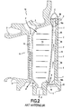
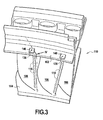
- the figure 1 is a perspective view of this known example of sector 10 and the figure 2 is a radial section according to plane II - II of the figure 1 .
- Sector 10 comprises an outer platform segment 2 and an inner platform segment 4, between which blades 6 extend to orient the flow of air in a direction favorable to the driving of the moving wheel. adjacent (not shown).
- To form a distributor several sectors are assembled together. Once assembled, the segments 2 form the annular inner platform of the dispenser, and the segments 4 form the annular outer platform of the dispenser.
- the blades 6 are hollow so as to be traversed by cooling air. Each dawn presents in its interior three cavities (see figure 2 ): a trailing edge cavity 16 (located on the trailing edge side of the blade), a leading edge cavity 12 (located on the leading edge side of the blade), and a central cavity 14 (located between the two aforementioned cavities). In operation, these three cavities 12, 14, 16 are supplied with cooling air. This cooling air is generally taken from the primary flow of the turbojet engine at the high pressure compressor. The path of the cooling air is symbolized schematically by the arrows F.
- the trailing edge cavity 16 is supplied with cooling air via the central cavity 14 and communication orifices 15 (in dashed line on the figure 2 ) between these two cavities 14, 16.
- the trailing edge cavity 16 communicates with a plurality of vents 18 (ie outlet channels) distributed along the trailing edge of the blade and passing through the intrados wall 19 of dawn.
- the vents 18 are shown in dotted lines on the figure 2 . They allow the evacuation of a part of the cooling air, according to the arrows f.
- the expelled air forms a film of air along the intrados wall 19, this air film protecting the trailing edge of the blade against the hot gases passing through the turbine, and cooling the trailing edge.
- the sector 10 is generally made in the foundry, the cavities 12, 14 and 16 being formed using soluble cores. To allow the evacuation of these soluble nuclei, the cavities 12, 14 and 16 are originally open at their outer and inner ends (ie upper and lower on the figure 2 ). After evacuation of the cores, the outer and inner openings of the cavities are closed.
- the outer opening 16a of the trailing edge cavity 16 and the inner opening 16b are respectively closed by plates 20 and 22.
- the plate 20 is made from a pre-sintered part which is positioned on the outer surface of the segment. 2 of the outer platform and then temperature rise, so that this pre-sintered part welds by welding-diffusion on the segment 2.
- a protective coating of aluminum is generally deposited on this sector by gaseous means.
- This known method generally consists in depositing aluminum on certain parts of the sector 10 (in particular the intrados and extrados surfaces of the blades 6) using a donor comprising aluminum, the aluminum being transported in the gaseous phase. from the donor to sector 10, in the form of aluminum halide.
- a gas commonly called “carrier gas,” capable of subliming under the thermal effect to release halogen ions.
- carrier gas capable of subliming under the thermal effect to release halogen ions.
- These ions react with the donor to form a volatile aluminum halide.
- This aluminum halide can be diluted with a reducing or inert gas, such as argon.
- the trailing edge cavity 16 is closed by the plates 20 and 22 before depositing the protective coating, since the plates 20 and 22 can not be welded to this coating.
- the gas used for the deposition of the coating ie the volatile aluminum halide and the inert gas in the above example
- Gas can possibly penetrate inside the vents 18, but these vents 18 having an opening section of very small size, the gas penetrates in very small quantities and a very small distance.
- the walls of the trailing edge cavity 16 are therefore not covered by the protective coating, or they are very slightly at the level of the vents 18.
- the object of the invention is to propose a turbine distributor sector of the aforementioned type, in which the area of the trailing edge cavity located near the outer platform segment, is less prone to hot corrosion.
- the air outlet hole provides a cooling air flow in the area of the trailing edge cavity located near the outer platform segment, so that this zone is better cooled and, thus, less prone to hot corrosion.
- a gaseous coating of a protective coating is carried out on the sector, so that a portion of the gas used for the deposition passes through the air outlet hole and the walls of the cavities located near this hole are covered by the protective coating.
- the protective coating is anti-corrosion, and the walls are even less prone to hot corrosion, since protected by this coating. It should be noted that this advantage can be obtained with any type of anti-corrosion coating and that the invention is therefore not limited to the deposition of an aluminum coating.
- the air outlet hole has a surface opening section greater than or equal to 2 mm 2 .
- the air outlet hole has a surface opening section of less than or equal to 8 mm 2 . This makes it possible to limit the discharge of cooling air at the exit hole. Indeed, an excessively large cooling air outlet at the exit hole would, in particular, reduce the flow of air evacuated via the vents, which would be detrimental to the cooling of the vanishing edge of the vanes.
- the air outlet hole is formed through a part fixed on the outer platform sector.
- the opening section of the hole can be made and calibrated before fixing the part.
- This part is chosen to be easy to handle, so that the calibration operation is easy and with a good degree of precision.
- This piece is, for example, a metal plate and can be fixed by brazing.
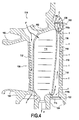
- sector 110 of figures 3 and 4 differs from sector 10 figures 1 and 2 only in the area of the trailing edge cavity at the outer platform. Also, the sector 110 parts similar to those of sector 10 are identified by the same numerical references increased by 100 and will not be described again.
- the sector 110 is made by casting and, initially, the trailing edge cavity 116 has an outer opening 116a at its outer end, this outer opening 116a through the outer deck segment 102.
- the outer opening 116a is useful for allowing the evacuation of the soluble core used to provide the cavity 116 with the interior of the blade 106, during molding.
- the section of the outer opening 116a is large enough that the core has at this location a sufficiently large thickness and is not likely to break.
- the section of the outer opening 116a has the general shape of a rectangle 8 mm long and 2 mm wide, an area of 16 mm 2 .
- This protective coating protecting against corrosion and oxidation.
- This protective coating is, for example, an aluminum coating.
- the method of depositing an aluminum coating is known and has been described above.
- the outer opening 116a of the trailing edge cavity is not closed: the cavity 116 communicates with an air outlet hole 130 present at the outer platform 102.
- this hole 130 allows the evacuation of a portion of the cooling air along the arrow f '.
- the protective coating a portion of the gas used for the deposition passes through the hole 130 and a coating is deposited on the walls of the cavity 116 located in the zone C. These walls are thus protected by the coating against corrosion.
- the opening section of the air outlet hole 130 is sufficiently wide to allow the passage of a sufficient quantity of gas during the deposition of the protective coating and to allow this gas to penetrate sufficiently far inside the cavity. 116.
- this opening section is narrow enough that the cooling air outlet (arrow f ') is not too great in operation.
- the opening section of the hole 130 has the general shape of a circle of 1.6 mm in diameter, an area of about 2 mm 2 .
- the air outlet hole 130 is formed through a metal plate 140.
- This plate 140 is rectangular or square. This plate 140 is brazed to the segment 102 of the outer platform. This plate 140 is chosen from a sufficiently hard and resistant to high temperature material, so that the surface of the section opening hole 130 remains constant or varies slightly in operation.
Landscapes
- Engineering & Computer Science (AREA)
- Mechanical Engineering (AREA)
- General Engineering & Computer Science (AREA)
- Turbine Rotor Nozzle Sealing (AREA)
Applications Claiming Priority (1)
| Application Number | Priority Date | Filing Date | Title |
|---|---|---|---|
| FR0756998A FR2919897B1 (fr) | 2007-08-08 | 2007-08-08 | Secteur de distributeur de turbine |
Publications (3)
| Publication Number | Publication Date |
|---|---|
| EP2025872A2 EP2025872A2 (fr) | 2009-02-18 |
| EP2025872A3 EP2025872A3 (fr) | 2011-04-20 |
| EP2025872B1 true EP2025872B1 (fr) | 2012-09-05 |
Family
ID=39099667
Family Applications (1)
| Application Number | Title | Priority Date | Filing Date |
|---|---|---|---|
| EP08161085A Active EP2025872B1 (fr) | 2007-08-08 | 2008-07-24 | Secteur de distributeur de turbine |
Country Status (8)
Families Citing this family (11)
| Publication number | Priority date | Publication date | Assignee | Title |
|---|---|---|---|---|
| FR2855557B1 (fr) * | 2003-05-26 | 2007-03-02 | Snecma Moteurs | Volet de tuyere a duree de vie augmentee pour turbomoteurs d'avion. |
| US8851846B2 (en) * | 2010-09-30 | 2014-10-07 | General Electric Company | Apparatus and methods for cooling platform regions of turbine rotor blades |
| US8628294B1 (en) * | 2011-05-19 | 2014-01-14 | Florida Turbine Technologies, Inc. | Turbine stator vane with purge air channel |
| US9169782B2 (en) * | 2012-01-04 | 2015-10-27 | General Electric Company | Turbine to operate at part-load |
| FR2989608B1 (fr) * | 2012-04-24 | 2015-01-30 | Snecma | Procede d'usinage du bord de fuite d'une aube de turbomachine |
| EP3047105B1 (en) | 2013-09-17 | 2021-06-09 | Raytheon Technologies Corporation | Platform cooling core for a gas turbine engine rotor blade |
| US11021967B2 (en) * | 2017-04-03 | 2021-06-01 | General Electric Company | Turbine engine component with a core tie hole |
| FR3074521B1 (fr) * | 2017-12-06 | 2019-11-22 | Safran Aircraft Engines | Secteur de distributeur de turbine pour une turbomachine d'aeronef |
| EP3530882A1 (en) * | 2018-02-26 | 2019-08-28 | MTU Aero Engines GmbH | Method of manufacturing a guide vane segment for a gas turbine and vane segment having a goating |
| CN113978240A (zh) * | 2021-10-29 | 2022-01-28 | 宁波信泰机械有限公司 | 一种主动进气格栅挤出叶片连接结构 |
| US12044143B2 (en) * | 2021-12-17 | 2024-07-23 | Rtx Corporation | Gas turbine engine component with manifold cavity and metering inlet orifices |
Family Cites Families (13)
| Publication number | Priority date | Publication date | Assignee | Title |
|---|---|---|---|---|
| JPH0693801A (ja) * | 1992-09-17 | 1994-04-05 | Hitachi Ltd | ガスタービン翼 |
| RU2088764C1 (ru) * | 1993-12-02 | 1997-08-27 | Яков Петрович Гохштейн | Турбинная лопатка |
| RU2122123C1 (ru) * | 1994-12-27 | 1998-11-20 | Открытое акционерное общество Самарский научно-технический комплекс им.Н.Д.Кузнецова | Охлаждаемая сопловая лопатка с вихревой матрицей |
| US6589668B1 (en) * | 2000-06-21 | 2003-07-08 | Howmet Research Corporation | Graded platinum diffusion aluminide coating |
| EP1191189A1 (de) * | 2000-09-26 | 2002-03-27 | Siemens Aktiengesellschaft | Gasturbinenschaufel |
| ITTO20010704A1 (it) * | 2001-07-18 | 2003-01-18 | Fiatavio Spa | Paletta a doppia parete per una turbina, particolarmente per applicazioni aeronautiche. |
| US6561757B2 (en) * | 2001-08-03 | 2003-05-13 | General Electric Company | Turbine vane segment and impingement insert configuration for fail-safe impingement insert retention |
| FR2830874B1 (fr) * | 2001-10-16 | 2004-01-16 | Snecma Moteurs | Procede de protection par aluminisation de pieces metalliques de turbomachines munies de trous et cavites |
| EP1361337B1 (en) * | 2002-05-09 | 2006-12-27 | General Electric Company | Turbine airfoil cooling configuration |
| US6929445B2 (en) * | 2003-10-22 | 2005-08-16 | General Electric Company | Split flow turbine nozzle |
| RU2267616C1 (ru) * | 2004-05-21 | 2006-01-10 | Федеральное государственное унитарное предприятие "Центральный институт авиационного моторостроения им. П.И. Баранова" | Охлаждаемая лопатка турбины |
| US7168921B2 (en) * | 2004-11-18 | 2007-01-30 | General Electric Company | Cooling system for an airfoil |
| FR2899271B1 (fr) * | 2006-03-29 | 2008-05-30 | Snecma Sa | Ensemble d'une aube et d'une chemise de refroidissement, distributeur de turbomachine comportant l'ensemble, turbomachine, procede de montage et de reparation de l'ensemble |
-
2007
- 2007-08-08 FR FR0756998A patent/FR2919897B1/fr active Active
-
2008
- 2008-07-24 EP EP08161085A patent/EP2025872B1/fr active Active
- 2008-07-24 ES ES08161085T patent/ES2394229T3/es active Active
- 2008-08-04 US US12/185,304 patent/US8192145B2/en active Active
- 2008-08-05 JP JP2008201496A patent/JP5442227B2/ja active Active
- 2008-08-07 RU RU2008132630/06A patent/RU2476680C2/ru active
- 2008-08-07 CN CN2008101458399A patent/CN101363328B/zh active Active
- 2008-08-07 CA CA2638812A patent/CA2638812C/fr active Active
Also Published As
| Publication number | Publication date |
|---|---|
| FR2919897A1 (fr) | 2009-02-13 |
| EP2025872A2 (fr) | 2009-02-18 |
| US8192145B2 (en) | 2012-06-05 |
| RU2008132630A (ru) | 2010-02-20 |
| FR2919897B1 (fr) | 2014-08-22 |
| JP5442227B2 (ja) | 2014-03-12 |
| CA2638812A1 (fr) | 2009-02-08 |
| US20090041586A1 (en) | 2009-02-12 |
| CN101363328B (zh) | 2013-04-17 |
| EP2025872A3 (fr) | 2011-04-20 |
| JP2009041566A (ja) | 2009-02-26 |
| CA2638812C (fr) | 2015-12-01 |
| RU2476680C2 (ru) | 2013-02-27 |
| CN101363328A (zh) | 2009-02-11 |
| ES2394229T3 (es) | 2013-01-23 |
Similar Documents
| Publication | Publication Date | Title |
|---|---|---|
| EP2025872B1 (fr) | Secteur de distributeur de turbine | |
| EP1840331B1 (fr) | Distributeur de turbomachine | |
| CA2652679C (fr) | Aubes pour roue a aubes de turbomachine avec rainure pour le refroidissement | |
| WO2013001240A1 (fr) | Joint d'etancheite a labyrinthe pour turbine d'un moteur a turbine a gaz | |
| EP3049637B1 (fr) | Ensemble rotatif pour turbomachine | |
| EP1911936B1 (fr) | Canal de transition entre deux étages de turbine | |
| EP2078824B1 (fr) | Aube à pales dédoublées, roue aubagée et turbomachine associées | |
| FR2981979A1 (fr) | Roue de turbine pour une turbomachine | |
| WO2023099533A1 (fr) | Turbomachine axiale triple-flux avec échangeur de chaleur divergeant dans le troisième flux | |
| EP1333155A1 (fr) | Aube mobile de turbine haute pression munie d'un bord de fuite refroidi | |
| EP1302558B1 (fr) | Procédé de protection par aluminisation de pièces métalliques de turbomachines munies de trous et cavités | |
| WO2021023945A1 (fr) | Anneau pour une turbine de turbomachine ou de turbomoteur | |
| EP3942158A1 (fr) | Aube de turbomachine equipee d'un circuit de refroidissement optimise | |
| WO2020239732A1 (fr) | Joint d'étanchéité dynamique pour turbomachine comprenant une pièce abradable multicouche | |
| FR2965843A1 (fr) | Rotor pour turbomachine | |
| FR3029242A1 (fr) | Aube de turbomachine, comprenant des cloisons entrecroisees pour la circulation d'air en direction du bord de fuite | |
| EP3712378A1 (fr) | Aube de turbomachine, comportant des deflecteurs dans une cavite interne de refroidissement | |
| FR3116466A1 (fr) | Préforme fibreuse d'un profil aérodynamique d'aube de turbomachine | |
| FR3028494A1 (fr) | Pale de turbomachine, comprenant des pontets s'etendant depuis la paroi d'intrados jusqu'a la paroi d'extrados | |
| FR3107720A1 (fr) | Aube de turbine, procédé de fabrication ou de reconditionnement du talon de ladite aube | |
| EP3847339B1 (fr) | Disque de rotor avec arret axial des aubes, ensemble d'un disque et d'un anneau et turbomachine | |
| EP4028656B1 (fr) | Panneau structural et/ou acoustique comprenant une bride de fermeture en u orientee vers l'interieur du panneau, et procede de fabrication d'un tel panneau | |
| EP4146913B1 (fr) | Distributeur en cmc amélioré pour turbine de turbomachine | |
| EP4111036B1 (fr) | Pale de distributeur pour turbomachine, distributeur haute ou basse pression pour turbomachine, turbomachine et procédé de fabrication d'une pale d'un distributeur pour turbomachine | |
| FR3158534A1 (fr) | Ensemble d’étanchéité, turbine et procédé de montage associés |
Legal Events
| Date | Code | Title | Description |
|---|---|---|---|
| PUAI | Public reference made under article 153(3) epc to a published international application that has entered the european phase |
Free format text: ORIGINAL CODE: 0009012 |
|
| 17P | Request for examination filed |
Effective date: 20080724 |
|
| AK | Designated contracting states |
Kind code of ref document: A2 Designated state(s): AT BE BG CH CY CZ DE DK EE ES FI FR GB GR HR HU IE IS IT LI LT LU LV MC MT NL NO PL PT RO SE SI SK TR |
|
| AX | Request for extension of the european patent |
Extension state: AL BA MK RS |
|
| PUAL | Search report despatched |
Free format text: ORIGINAL CODE: 0009013 |
|
| AK | Designated contracting states |
Kind code of ref document: A3 Designated state(s): AT BE BG CH CY CZ DE DK EE ES FI FR GB GR HR HU IE IS IT LI LT LU LV MC MT NL NO PL PT RO SE SI SK TR |
|
| AX | Request for extension of the european patent |
Extension state: AL BA MK RS |
|
| AKX | Designation fees paid |
Designated state(s): DE ES FR GB IT |
|
| GRAP | Despatch of communication of intention to grant a patent |
Free format text: ORIGINAL CODE: EPIDOSNIGR1 |
|
| GRAS | Grant fee paid |
Free format text: ORIGINAL CODE: EPIDOSNIGR3 |
|
| GRAA | (expected) grant |
Free format text: ORIGINAL CODE: 0009210 |
|
| AK | Designated contracting states |
Kind code of ref document: B1 Designated state(s): DE ES FR GB IT |
|
| REG | Reference to a national code |
Ref country code: GB Ref legal event code: FG4D Free format text: NOT ENGLISH |
|
| REG | Reference to a national code |
Ref country code: DE Ref legal event code: R096 Ref document number: 602008018530 Country of ref document: DE Effective date: 20121031 |
|
| REG | Reference to a national code |
Ref country code: ES Ref legal event code: FG2A Ref document number: 2394229 Country of ref document: ES Kind code of ref document: T3 Effective date: 20130123 |
|
| PLBE | No opposition filed within time limit |
Free format text: ORIGINAL CODE: 0009261 |
|
| STAA | Information on the status of an ep patent application or granted ep patent |
Free format text: STATUS: NO OPPOSITION FILED WITHIN TIME LIMIT |
|
| 26N | No opposition filed |
Effective date: 20130606 |
|
| REG | Reference to a national code |
Ref country code: DE Ref legal event code: R097 Ref document number: 602008018530 Country of ref document: DE Effective date: 20130606 |
|
| REG | Reference to a national code |
Ref country code: ES Ref legal event code: FD2A Effective date: 20140807 |
|
| PG25 | Lapsed in a contracting state [announced via postgrant information from national office to epo] |
Ref country code: ES Free format text: LAPSE BECAUSE OF NON-PAYMENT OF DUE FEES Effective date: 20130725 |
|
| REG | Reference to a national code |
Ref country code: FR Ref legal event code: PLFP Year of fee payment: 9 |
|
| REG | Reference to a national code |
Ref country code: FR Ref legal event code: PLFP Year of fee payment: 10 |
|
| REG | Reference to a national code |
Ref country code: FR Ref legal event code: CD Owner name: SAFRAN AIRCRAFT ENGINES, FR Effective date: 20170719 |
|
| REG | Reference to a national code |
Ref country code: FR Ref legal event code: PLFP Year of fee payment: 11 |
|
| PGFP | Annual fee paid to national office [announced via postgrant information from national office to epo] |
Ref country code: GB Payment date: 20240620 Year of fee payment: 17 |
|
| PGFP | Annual fee paid to national office [announced via postgrant information from national office to epo] |
Ref country code: FR Payment date: 20240619 Year of fee payment: 17 |
|
| PGFP | Annual fee paid to national office [announced via postgrant information from national office to epo] |
Ref country code: IT Payment date: 20240619 Year of fee payment: 17 |
|
| PGFP | Annual fee paid to national office [announced via postgrant information from national office to epo] |
Ref country code: DE Payment date: 20240619 Year of fee payment: 17 |