EP2025870A2 - Verfahren zur Modifizierung einer Gasturbinenschaufel - Google Patents
Verfahren zur Modifizierung einer Gasturbinenschaufel Download PDFInfo
- Publication number
- EP2025870A2 EP2025870A2 EP20080161606 EP08161606A EP2025870A2 EP 2025870 A2 EP2025870 A2 EP 2025870A2 EP 20080161606 EP20080161606 EP 20080161606 EP 08161606 A EP08161606 A EP 08161606A EP 2025870 A2 EP2025870 A2 EP 2025870A2
- Authority
- EP
- European Patent Office
- Prior art keywords
- blade
- holes
- tentative
- calculating
- cooling circuit
- Prior art date
- Legal status (The legal status is an assumption and is not a legal conclusion. Google has not performed a legal analysis and makes no representation as to the accuracy of the status listed.)
- Withdrawn
Links
- 238000000034 method Methods 0.000 title claims abstract description 45
- 238000001816 cooling Methods 0.000 claims abstract description 53
- 239000012809 cooling fluid Substances 0.000 claims abstract description 19
- 239000012530 fluid Substances 0.000 claims description 2
- 238000005050 thermomechanical fatigue Methods 0.000 description 3
- 238000004364 calculation method Methods 0.000 description 2
- 238000005259 measurement Methods 0.000 description 2
- 230000008646 thermal stress Effects 0.000 description 2
- 238000004458 analytical method Methods 0.000 description 1
- 238000009533 lab test Methods 0.000 description 1
- 239000000463 material Substances 0.000 description 1
- 238000013021 overheating Methods 0.000 description 1
- 230000001737 promoting effect Effects 0.000 description 1
- 238000004088 simulation Methods 0.000 description 1
- 238000002076 thermal analysis method Methods 0.000 description 1
Images



Classifications
-
- F—MECHANICAL ENGINEERING; LIGHTING; HEATING; WEAPONS; BLASTING
- F01—MACHINES OR ENGINES IN GENERAL; ENGINE PLANTS IN GENERAL; STEAM ENGINES
- F01D—NON-POSITIVE DISPLACEMENT MACHINES OR ENGINES, e.g. STEAM TURBINES
- F01D5/00—Blades; Blade-carrying members; Heating, heat-insulating, cooling or antivibration means on the blades or the members
- F01D5/12—Blades
- F01D5/14—Form or construction
- F01D5/18—Hollow blades, i.e. blades with cooling or heating channels or cavities; Heating, heat-insulating or cooling means on blades
- F01D5/186—Film cooling
-
- F—MECHANICAL ENGINEERING; LIGHTING; HEATING; WEAPONS; BLASTING
- F05—INDEXING SCHEMES RELATING TO ENGINES OR PUMPS IN VARIOUS SUBCLASSES OF CLASSES F01-F04
- F05D—INDEXING SCHEME FOR ASPECTS RELATING TO NON-POSITIVE-DISPLACEMENT MACHINES OR ENGINES, GAS-TURBINES OR JET-PROPULSION PLANTS
- F05D2230/00—Manufacture
- F05D2230/80—Repairing, retrofitting or upgrading methods
Definitions
- the present invention relates to a method for modifying a gas turbine blade. Specifically, the present invention relates to a method for modifying a gas turbine blade which, during system operation, highlighted damages caused by overheating.
- a known type of gas turbine blade extends along a longitudinal axis and is provided with a cooling circuit in which a cooling fluid, generally air, flows.
- the cooling circuit includes a pipe coil-arranged inside the blade, which communicates with the outside of the blade by means of channels, essentially orthogonal to the blade axis and leading at the trailing edge of the blade.
- the air flow which flows in the cooling circuit removes heat by convection and lowers the temperature of the blade.
- the leading edge of the blade is the zone which is the most subjected to this type of damage because its geometric conformation makes the internal convection cooling thereof extremely difficult.
- thermo-mechanical fatigue damages are repaired and reinstalled on the turbine because replacing the damaged blade with a new blade is too expensive. Repairing the damage, however, does not eliminate the problem of thermo-mechanical fatigue damages, which reoccur after a short time and essentially in the same points.
- the present invention relates to a method for modifying a gas turbine blade provided with an internal cooling circuit in which a cooling fluid flows; the method being characterized in that it includes the steps of:
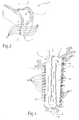
- reference number 1 indicates a blade of a gas turbine (not shown in the accompanying figures for simplicity), which extends along an axis A and is provided with a cooling circuit 3 in which a cooling fluid flows.
- the blade 1 comprises a leading edge 4, a trailing edge 5, a lower base 6, and an upper base 7, opposite to the lower base 6.
- the cooling circuit 3 includes a pipe 9, coil-arranged and essentially defined by three segments 9a, 9b, 9c parallel to the axis A, an exhaust channel 10 arranged on the lower base 6 of the blade 1, and a plurality of channels 12, essentially arranged orthogonally to axis A of the blade along the trailing edge 5 of the blade 1.
- the cooling fluid generally air, enters the pipe 9 at the upper base 7 of the blade 1, flows in the pipe 9 and exits from the blade 1 through the exhaust channel 10 and the channels 12 (as shown by the arrows in figure).
- the cooling fluid flow inside the cooling circuit 3 allows to remove heat by convection and thus to lower the external temperature T E of the blade 1.
- Figure 3 shows the blade 1 modified in accordance with the method for modifying a gas turbine blade according to the present invention.
- the modified blade 1 includes a plurality of film cooling holes 16 arranged along the leading edge 4.
- the film cooling holes 16 are made along the leading edge 4, which is the most stressed zone from a thermal point of view during the operation of the blade 1 and thus requires a more incisive cooling action. It is understood that the method for modifying a blade, which will be described hereinafter, provides for calculating the optimal configuration, designing and making the film cooling holes 16 in each zone of the blade 1 which has shown thermal strength problems.
- FIG 4 shows the cooling circuit 3 of the blade 1 modified in accordance with the method for modifying a blade according to the present invention.
- the segment 9a of the modified cooling circuit 3 is directly connected to the through holes 16. Through the holes 16 the cooling fluid flows, which laps on the external surface of the modified blade 1, thus promoting the lowering of the external temperature T E in the zone located about the holes 16.
- the zone of the blade 1 which is externally lapped by the cooling fluid is the leading edge 4.
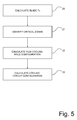
- the method for modifying a gas turbine blade according to the present invention essentially includes the steps of:
- such a method applies to blades which have shown the presence of cracks during the laboratory tests which are normally carried out after approximately 25000 working hours. These tests usually include the use of fluorescent fluids which penetrate into the cracks, thus highlighting them.
- the method firstly includes supplying a numeric model of the cooling circuit 3 of the blade 1 (block 26).
- the numeric model of the cooling circuit 3 is essentially a combination of models (curve, pipe, bottleneck), the fluid-dynamic variable simulation of which is known.
- the method then includes measuring a flow rate Q M of the cooling fluid flowing in the cooling circuit 3 of the blade 1 (block 27); preferably, such a measurement is experimentally carried out by connecting the blade 1 to a pressurized circuit (not shown in the accompanying figures) provided with flow rate meters.
- the numeric model of the cooling circuit 3 is calibrated according to the flow rate value Q M of the cooling fluid (block 29) and tentative values T ET of the external temperature of the blade 1 along a plurality of sections of the blade are determined (block 30).
- the method includes calculating the values of the internal heat exchange coefficient C I and the values of the external heat exchange coefficient C E along the plurality of sections of the blade (block 31).
- the external heat exchange coefficient C E is preferably calculated by means of the fluid-dynamic analysis of the thermal flow between gas and blade 1
- the internal heat exchange coefficient C I is preferably calculated by means of a one-dimensional thermal analysis to evaluate the thermal flow between cooling fluid and blade 1.
- the method includes updating the value or the values of the tentative external temperature T ET , otherwise the tentative values T ET are considered as external temperature T E of the blade 1 (block 33).
- the step of calculating the configuration of the plurality of holes 16 includes calculating the number N of through holes 16 and the diameter D of the holes 16 to be made in the blade 1.
- the method provides for determining a tentative diameter value D T of the holes 16 (block 35); determining a tentative number of holes N T (block 36); calculating external temperature values T E of the blade 1 according to the tentative number of holes N T and to the tentative diameter value D T (block 37); updating the tentative number of holes N T if at least one external temperature value T E is higher than the predetermined limit T L and updating the tentative diameter value D T of the holes 16 if at least one external temperature value T E is higher than the predetermined limit T L (critical condition) and if the tentative number of holes N T is higher than a maximum number of holes N L , defined beforehand on the basis of structural considerations.
- the step of calculating the configuration of the plurality of holes 16 may be similarly carried out by firstly determining a tentative number of holes N T (block 50); determining a tentative diameter D T (block 51); calculating the external temperature T E of the blade 1 according to the tentative diameter value D T of the holes 16 and the tentative number of holes N T (block 52); updating the tentative diameter D T if at least one external temperature value T E is higher than the predetermined limit T L and finally updating the tentative number of holes N T if at least one external temperature value T E is higher than the predetermined limit T L and if the tentative diameter value D T is higher than a maximum diameter value D L .
- the method provides for selectively calculating a new configuration of the cooling circuit 3 of the blade 1 (block 23). Specifically, the calculation of the new configuration of the cooling circuit 3 is carried out if the available flow rate Q M of the cooling fluid which is measured on the blade 1 before making the holes 16 is not sufficient for the new cooling system 3 provided with film cooling holes 16. Therefore, the method firstly provides for measuring the available flow rate Q M of cooling fluid (block 60); such a measurement is carried out experimentally on the blade 1 which needs to be modified.
- the method provides for calculating the requested flow rate Q C of the cooling fluid flowing in the cooling circuit 3 connected to the holes 16 (block 61); such a flow rate Q C is calculated considering the previously described numeric model.
- the method provides for modifying the cooling circuit 3 so that the requested flow rate Q C is either lower than or equal to the available flow rate Q M .
- modifying the cooling circuit 3 includes calculating new tentative passage sections S T of the cooling circuit 3 (block 62) and recalculating the requested flow rate Q C (block 61) assuming that the cooling circuit is provided with the new tentative passage sections S T . If the requested, newly calculated flow rate Q C is still higher than the available flow rate Q M , the tentative passage sections S T are updated (block 62) and the requested flow rate Q C is recalculated (block 61).
- the method provides for making holes 16 in the blade 1 according to the calculated configuration of the holes 16, and for possibly modifying the sections of the cooling circuit 3 of the blade 1 according to the calculated new configuration of the cooling circuit 3.
- the present invention has the following advantages.
- the method according to the present invention is particularly fast and effective for designing the configuration of film cooling holes and of the cooling circuit. Indeed, the method may essentially be fully automated and uses practical and fast calculation tools.
Landscapes
- Engineering & Computer Science (AREA)
- Mechanical Engineering (AREA)
- General Engineering & Computer Science (AREA)
- Turbine Rotor Nozzle Sealing (AREA)
- Separation By Low-Temperature Treatments (AREA)
Applications Claiming Priority (1)
| Application Number | Priority Date | Filing Date | Title |
|---|---|---|---|
| ITMI20071564 ITMI20071564A1 (it) | 2007-07-31 | 2007-07-31 | Metodo per modificare una pala di una turbina a gas |
Publications (1)
| Publication Number | Publication Date |
|---|---|
| EP2025870A2 true EP2025870A2 (de) | 2009-02-18 |
Family
ID=40001382
Family Applications (1)
| Application Number | Title | Priority Date | Filing Date |
|---|---|---|---|
| EP20080161606 Withdrawn EP2025870A2 (de) | 2007-07-31 | 2008-07-31 | Verfahren zur Modifizierung einer Gasturbinenschaufel |
Country Status (2)
| Country | Link |
|---|---|
| EP (1) | EP2025870A2 (de) |
| IT (1) | ITMI20071564A1 (de) |
Cited By (1)
| Publication number | Priority date | Publication date | Assignee | Title |
|---|---|---|---|---|
| CN104088671A (zh) * | 2014-07-10 | 2014-10-08 | 东北电力大学 | 基于多参数影响下的气膜冷却效果正交预测方法 |
-
2007
- 2007-07-31 IT ITMI20071564 patent/ITMI20071564A1/it unknown
-
2008
- 2008-07-31 EP EP20080161606 patent/EP2025870A2/de not_active Withdrawn
Cited By (2)
| Publication number | Priority date | Publication date | Assignee | Title |
|---|---|---|---|---|
| CN104088671A (zh) * | 2014-07-10 | 2014-10-08 | 东北电力大学 | 基于多参数影响下的气膜冷却效果正交预测方法 |
| CN104088671B (zh) * | 2014-07-10 | 2016-01-20 | 东北电力大学 | 基于多参数影响下的气膜冷却效果正交预测方法 |
Also Published As
| Publication number | Publication date |
|---|---|
| ITMI20071564A1 (it) | 2009-02-01 |
Similar Documents
| Publication | Publication Date | Title |
|---|---|---|
| EP2679778B1 (de) | Verfahren zum Messen der Geometrie von Verformungen eines Turbinenbauteils | |
| CN113188781B (zh) | 航空发动机叶片疲劳试验中对转子温度场进行修正的方法 | |
| CN107084844A (zh) | 一种叶片结构模拟件的试验方法 | |
| KR20120034799A (ko) | 자동 수리 방법 및 시스템 | |
| EP2540962A2 (de) | Verfahren zur Erstellung von Leitschaufelsegmenten | |
| JP6883121B2 (ja) | 稼働中に腐食損傷を受けるパワータービンのディスクの長寿命化 | |
| CN114235319B (zh) | 一种空心涡轮叶片试验装置及方法 | |
| CN105043914A (zh) | 一种评定高温合金热疲劳性的试验方法及装置 | |
| CN118391962A (zh) | 一种管壳式换热器强化传热方法 | |
| EP2025870A2 (de) | Verfahren zur Modifizierung einer Gasturbinenschaufel | |
| CN106181220B (zh) | 一种铝合金焊后火焰调修工艺 | |
| CN115758603A (zh) | 航空发动机涡轮叶片多工况蠕变/应力断裂寿命预测方法 | |
| US7970555B2 (en) | Method for developing a repair process to correct a deformed gas turbine engine component | |
| EP2975314B1 (de) | Verfahren zur verlängerung der lebensdauer von hochtemperaturröhren und struktur zur verlängerung der lebensdauer von hochtemperaturröhren | |
| CN103470314A (zh) | 用于在操作之前确定涡轮机部件的蠕变性能的方法和系统 | |
| US8322202B2 (en) | Method for inspecting a turbine installation and corresponding device | |
| JPH09195795A (ja) | ガスタービン静翼の余寿命評価方法およびその装置 | |
| CN115533231B (zh) | 一种高涡叶片榫头冷却孔补加工方法 | |
| JP2019157832A (ja) | ガスタービン静翼の補修判定装置およびガスタービン静翼の補修判定方法 | |
| CN113029075B (zh) | 现场快速判别火电厂用高温奥氏体钢炉管老化损伤程度的方法 | |
| DE102004002965A1 (de) | Verfahren und Vorrichtung zur Reparatur von integral beschaufelten Rotoren | |
| CN114813329A (zh) | 一种镍基单晶高温合金随机蠕变载荷下的剩余寿命预测方法 | |
| JP3303685B2 (ja) | 構造部品の保守管理装置及び保守管理方法 | |
| JPH02136713A (ja) | プラント設備診断システム | |
| CN113235461B (zh) | 一种悬索桥索夹耳孔和箱梁耳孔的修复方法 |
Legal Events
| Date | Code | Title | Description |
|---|---|---|---|
| PUAI | Public reference made under article 153(3) epc to a published international application that has entered the european phase |
Free format text: ORIGINAL CODE: 0009012 |
|
| AK | Designated contracting states |
Kind code of ref document: A2 Designated state(s): AT BE BG CH CY CZ DE DK EE ES FI FR GB GR HR HU IE IS IT LI LT LU LV MC MT NL NO PL PT RO SE SI SK TR |
|
| AX | Request for extension of the european patent |
Extension state: AL BA MK RS |
|
| STAA | Information on the status of an ep patent application or granted ep patent |
Free format text: STATUS: THE APPLICATION IS DEEMED TO BE WITHDRAWN |
|
| 18D | Application deemed to be withdrawn |
Effective date: 20130201 |