EP2025449B1 - Machine tool with automatic tool changer - Google Patents
Machine tool with automatic tool changer Download PDFInfo
- Publication number
- EP2025449B1 EP2025449B1 EP08013829A EP08013829A EP2025449B1 EP 2025449 B1 EP2025449 B1 EP 2025449B1 EP 08013829 A EP08013829 A EP 08013829A EP 08013829 A EP08013829 A EP 08013829A EP 2025449 B1 EP2025449 B1 EP 2025449B1
- Authority
- EP
- European Patent Office
- Prior art keywords
- tool
- changing
- tools
- changing unit
- axis
- Prior art date
- Legal status (The legal status is an assumption and is not a legal conclusion. Google has not performed a legal analysis and makes no representation as to the accuracy of the status listed.)
- Active
Links
- 238000003754 machining Methods 0.000 claims abstract description 49
- 230000008859 change Effects 0.000 claims description 21
- 230000007246 mechanism Effects 0.000 claims description 14
- 238000004904 shortening Methods 0.000 abstract description 2
- 238000003860 storage Methods 0.000 description 11
- 238000000034 method Methods 0.000 description 6
- 230000008569 process Effects 0.000 description 6
- 238000005520 cutting process Methods 0.000 description 3
- 239000002826 coolant Substances 0.000 description 2
- 230000002441 reversible effect Effects 0.000 description 2
- 239000003638 chemical reducing agent Substances 0.000 description 1
- 238000005516 engineering process Methods 0.000 description 1
- 239000000463 material Substances 0.000 description 1
- 238000012986 modification Methods 0.000 description 1
- 230000004048 modification Effects 0.000 description 1
Images


Classifications
-
- B—PERFORMING OPERATIONS; TRANSPORTING
- B23—MACHINE TOOLS; METAL-WORKING NOT OTHERWISE PROVIDED FOR
- B23Q—DETAILS, COMPONENTS, OR ACCESSORIES FOR MACHINE TOOLS, e.g. ARRANGEMENTS FOR COPYING OR CONTROLLING; MACHINE TOOLS IN GENERAL CHARACTERISED BY THE CONSTRUCTION OF PARTICULAR DETAILS OR COMPONENTS; COMBINATIONS OR ASSOCIATIONS OF METAL-WORKING MACHINES, NOT DIRECTED TO A PARTICULAR RESULT
- B23Q3/00—Devices holding, supporting, or positioning work or tools, of a kind normally removable from the machine
- B23Q3/155—Arrangements for automatic insertion or removal of tools, e.g. combined with manual handling
- B23Q3/157—Arrangements for automatic insertion or removal of tools, e.g. combined with manual handling of rotary tools
- B23Q3/15713—Arrangements for automatic insertion or removal of tools, e.g. combined with manual handling of rotary tools a transfer device taking a single tool from a storage device and inserting it in a spindle
- B23Q3/1572—Arrangements for automatic insertion or removal of tools, e.g. combined with manual handling of rotary tools a transfer device taking a single tool from a storage device and inserting it in a spindle the storage device comprising rotating or circulating storing means
- B23Q3/15753—Arrangements for automatic insertion or removal of tools, e.g. combined with manual handling of rotary tools a transfer device taking a single tool from a storage device and inserting it in a spindle the storage device comprising rotating or circulating storing means the storage means rotating or circulating in a plane perpendicular to the axis of the spindle
- B23Q3/15766—Arrangements for automatic insertion or removal of tools, e.g. combined with manual handling of rotary tools a transfer device taking a single tool from a storage device and inserting it in a spindle the storage device comprising rotating or circulating storing means the storage means rotating or circulating in a plane perpendicular to the axis of the spindle the axis of the stored tools being arranged perpendicularly to the rotating or circulating plane of the storage means
-
- B—PERFORMING OPERATIONS; TRANSPORTING
- B23—MACHINE TOOLS; METAL-WORKING NOT OTHERWISE PROVIDED FOR
- B23Q—DETAILS, COMPONENTS, OR ACCESSORIES FOR MACHINE TOOLS, e.g. ARRANGEMENTS FOR COPYING OR CONTROLLING; MACHINE TOOLS IN GENERAL CHARACTERISED BY THE CONSTRUCTION OF PARTICULAR DETAILS OR COMPONENTS; COMBINATIONS OR ASSOCIATIONS OF METAL-WORKING MACHINES, NOT DIRECTED TO A PARTICULAR RESULT
- B23Q11/00—Accessories fitted to machine tools for keeping tools or parts of the machine in good working condition or for cooling work; Safety devices specially combined with or arranged in, or specially adapted for use in connection with, machine tools
- B23Q11/08—Protective coverings for parts of machine tools; Splash guards
- B23Q11/0891—Protective coverings for parts of machine tools; Splash guards arranged between the working area and the operator
-
- Y—GENERAL TAGGING OF NEW TECHNOLOGICAL DEVELOPMENTS; GENERAL TAGGING OF CROSS-SECTIONAL TECHNOLOGIES SPANNING OVER SEVERAL SECTIONS OF THE IPC; TECHNICAL SUBJECTS COVERED BY FORMER USPC CROSS-REFERENCE ART COLLECTIONS [XRACs] AND DIGESTS
- Y10—TECHNICAL SUBJECTS COVERED BY FORMER USPC
- Y10T—TECHNICAL SUBJECTS COVERED BY FORMER US CLASSIFICATION
- Y10T29/00—Metal working
- Y10T29/51—Plural diverse manufacturing apparatus including means for metal shaping or assembling
- Y10T29/5104—Type of machine
- Y10T29/5109—Lathe
- Y10T29/5114—Lathe and tool
-
- Y—GENERAL TAGGING OF NEW TECHNOLOGICAL DEVELOPMENTS; GENERAL TAGGING OF CROSS-SECTIONAL TECHNOLOGIES SPANNING OVER SEVERAL SECTIONS OF THE IPC; TECHNICAL SUBJECTS COVERED BY FORMER USPC CROSS-REFERENCE ART COLLECTIONS [XRACs] AND DIGESTS
- Y10—TECHNICAL SUBJECTS COVERED BY FORMER USPC
- Y10T—TECHNICAL SUBJECTS COVERED BY FORMER US CLASSIFICATION
- Y10T483/00—Tool changing
- Y10T483/11—Tool changing with safety means
- Y10T483/115—Guard
-
- Y—GENERAL TAGGING OF NEW TECHNOLOGICAL DEVELOPMENTS; GENERAL TAGGING OF CROSS-SECTIONAL TECHNOLOGIES SPANNING OVER SEVERAL SECTIONS OF THE IPC; TECHNICAL SUBJECTS COVERED BY FORMER USPC CROSS-REFERENCE ART COLLECTIONS [XRACs] AND DIGESTS
- Y10—TECHNICAL SUBJECTS COVERED BY FORMER USPC
- Y10T—TECHNICAL SUBJECTS COVERED BY FORMER US CLASSIFICATION
- Y10T483/00—Tool changing
- Y10T483/12—Tool changing with means to regulate operation by means of replaceable information supply [e.g., templet, tape, card, etc. ]
- Y10T483/123—Replaceable information comprising tool location
- Y10T483/127—Replaceable information comprising tool location including determining optimum tool access path
-
- Y—GENERAL TAGGING OF NEW TECHNOLOGICAL DEVELOPMENTS; GENERAL TAGGING OF CROSS-SECTIONAL TECHNOLOGIES SPANNING OVER SEVERAL SECTIONS OF THE IPC; TECHNICAL SUBJECTS COVERED BY FORMER USPC CROSS-REFERENCE ART COLLECTIONS [XRACs] AND DIGESTS
- Y10—TECHNICAL SUBJECTS COVERED BY FORMER USPC
- Y10T—TECHNICAL SUBJECTS COVERED BY FORMER US CLASSIFICATION
- Y10T483/00—Tool changing
- Y10T483/13—Tool changing with control means energized in response to activator stimulated by condition sensor
- Y10T483/136—Responsive to tool
- Y10T483/138—Responsive to tool including means to monitor and control, i.e., adaptive machining
-
- Y—GENERAL TAGGING OF NEW TECHNOLOGICAL DEVELOPMENTS; GENERAL TAGGING OF CROSS-SECTIONAL TECHNOLOGIES SPANNING OVER SEVERAL SECTIONS OF THE IPC; TECHNICAL SUBJECTS COVERED BY FORMER USPC CROSS-REFERENCE ART COLLECTIONS [XRACs] AND DIGESTS
- Y10—TECHNICAL SUBJECTS COVERED BY FORMER USPC
- Y10T—TECHNICAL SUBJECTS COVERED BY FORMER US CLASSIFICATION
- Y10T483/00—Tool changing
- Y10T483/17—Tool changing including machine tool or component
- Y10T483/1702—Rotating work machine tool [e.g., screw machine, lathe, etc.]
- Y10T483/1705—Tool support comprises rotary spindle
-
- Y—GENERAL TAGGING OF NEW TECHNOLOGICAL DEVELOPMENTS; GENERAL TAGGING OF CROSS-SECTIONAL TECHNOLOGIES SPANNING OVER SEVERAL SECTIONS OF THE IPC; TECHNICAL SUBJECTS COVERED BY FORMER USPC CROSS-REFERENCE ART COLLECTIONS [XRACs] AND DIGESTS
- Y10—TECHNICAL SUBJECTS COVERED BY FORMER USPC
- Y10T—TECHNICAL SUBJECTS COVERED BY FORMER US CLASSIFICATION
- Y10T483/00—Tool changing
- Y10T483/17—Tool changing including machine tool or component
- Y10T483/1702—Rotating work machine tool [e.g., screw machine, lathe, etc.]
- Y10T483/1714—Tool changer between tool support and matrix
- Y10T483/1724—Linearly moveable tool changer
-
- Y—GENERAL TAGGING OF NEW TECHNOLOGICAL DEVELOPMENTS; GENERAL TAGGING OF CROSS-SECTIONAL TECHNOLOGIES SPANNING OVER SEVERAL SECTIONS OF THE IPC; TECHNICAL SUBJECTS COVERED BY FORMER USPC CROSS-REFERENCE ART COLLECTIONS [XRACs] AND DIGESTS
- Y10—TECHNICAL SUBJECTS COVERED BY FORMER USPC
- Y10T—TECHNICAL SUBJECTS COVERED BY FORMER US CLASSIFICATION
- Y10T483/00—Tool changing
- Y10T483/17—Tool changing including machine tool or component
- Y10T483/1733—Rotary spindle machine tool [e.g., milling machine, boring, machine, grinding machine, etc.]
- Y10T483/179—Direct tool exchange between spindle and matrix
- Y10T483/1793—Spindle comprises tool changer
- Y10T483/1795—Matrix indexes selected tool to transfer position
Definitions
- the present invention relates to a machine tool having a tool magazine and an automatic machine changer for changing a tool.
- Machine tools with an automatic tool changer (hereinafter also referred to as "ATC") are disclosed in U.S. patent 4,729,159 and Japanese laid-open patent publication No. 59-227345 , for example.
- the ATC disclosed in U.S. patent 4,729,159 includes a feeder for gripping and feeding a tool, which travels outside the machining area of the machine tool.
- the machine tool disclosed in Japanese laid-open patent publication No. 59-227345 includes a tool magazine for storing tools therein. The magazine itself is movable, and the ATC changes tools between the magazine and a tool rest.
- the ATC disclosed in U.S. patent 4,729,159 has a predetermined tool changing position with respect to a tool rest.
- the tool rest For changing tools, the tool rest has to move from a machining position to the tool changing position.
- the tool rest needs to move a long distance to the tool changing position, it is time-consuming to replace the tool on the tool rest with another tool. Accordingly, the machining tool has a long non-machining time.
- a movable unit including a tool magazine is heavy and cannot move at a high speed. Furthermore, a mechanism for moving the tool magazine is large and complex, imposing limitations on the number of tools that can be stored in the tool magazine.
- ATCs include a tool feeder disposed between a tool magazine and a tool changer arm. Tools are changed between the tool magazine and the tool changer arm via the tool feeder.
- these ATCs with the tool feeder are structurally complex in their entirety.
- JP 02 053542 A is a machine tool according to the preamble of claim 1.
- a machine tool is provided in accordance with claim 1.
- the tool changing unit is controlled to wait in one position, of waiting positions, which is close to the selected changing position; and when a tool change start signal is output, the tool spindle may move to cause the tool to reach the selected changing position, and the tool changing unit may move and change the tools on the tool spindle in the selected changing position.
- the machine tool has a long machining area which is elongate in a horizontal direction; the horizontally long machining area is covered with the splash guard; and the tool changing unit is disposed outside of the splash guard and is movable in the horizontal direction and is capable of waiting selectively in waiting positions near the shutters, respectively.
- the shutters are placed on the ceiling panel of the splash guard along the horizontal direction; and the tool changing unit is movable above the ceiling panel of the splash guard in the horizontal direction along the shutters.
- the tool changing unit comprises: a unit frame supported and guided by a traveling mechanism and actuated by a linearly driving servomotor to move in a displacing direction; a reciprocally movable member supported on the unit frame and actuated by a reciprocally driving servomotor to move reciprocally in a first direction perpendicular to the displacing direction; and an arm mounted on the reciprocally movable member and actuated to be swiveled by a swiveling servomotor, the arm having at least two tool grippers for detachably gripping the tool.
- the machine tool is capable of machining the workpiece which is elongate; and when the long workpiece is machined with the tool, the tool changing unit transfers and changes the tool for successively using the tools stored in the tool magazine.
- the machine tool comprises a multi-axis turning center including a headstock for rotatably supporting a workpiece spindle having a chuck for gripping the workpiece, and a tool rest having the tool spindle.
- the tool changed by the tool changing unit comprises a cutter detachably mounted on a distal end of a boring bar mounted on the tool spindle of the tool rest; and the tool rest moves to cause the cutter to reach to the selected changing position and the tool changing unit is controlled to change the cutter on the boring bar mounted on the tool spindle.
- the machine tool having the automatic tool changer according to the present invention is constructed as described above. Since the tool changing unit and the tool mounted on the tool spindle move to a selected changing position, the distances which the tool changing unit and the tool spindle move for changing the tools are reduced thereby to shorten the non-machining time of the machine tool.
- a machine tool having an automatic tool changer comprises an automatic tool changer, a tool magazine for storing a plurality of tools, and a tool spindle for mounting a tool thereon and machining a workpiece with the tool.
- the automatic tool changer includes a movable tool changing unit (hereinafter referred to as "changing unit") for changing the tools.
- the changing unit moves between a magazine position and a changing position, and transfers the tools in the magazine position and the changing position.
- the changing position the changing unit replaces the tool on the tool spindle with another tool.
- the changing unit replaces the tool thereon with another tool from the magazine.
- the machine tool has a plurality of changing positions. One of the changing positions is selected in advance for changing the tools next time. And then, the changing unit and the tool mounted on the tool spindle move to the selected changing position in which the changing unit replaces the tool on the tool spindle with another tool. Therefore, the changing unit and the tool spindle move relatively small distances, respectively, for changing the tools, thereby shortening the non-machining time of the machine tool.
- the machine tool having the automatic tool changer comprises a multi-axis turning center.
- the machine tool may comprise a lathe having a tool spindle on a tool rest, a machining center having a tool spindle on a spindle head, a turning center or a grinding machine.
- a machine tool having an automatic tool changer according to a preferred embodiment of the present invention will be described below with reference to FIGS. 1 through 19 .
- FIG. 1 is a perspective view of the machine tool.
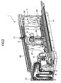
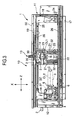
- FIGS. 2 and 3 are perspective and front elevational views, respectively, showing structural details of the machine tool.
- FIG. 4 is a front elevational view showing structural details of the machine tool at the time it employs a boring bar.
- FIG. 5 is a side elevational view of the machine tool as from the right in FIG. 3 .
- FIG. 6 is a fragmentary perspective view of an automatic tool changer of the machine tool.
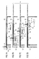
- FIGS. 7A through 7D are schematic front elevational views illustrating a tool changing process.
- the machine tool 1 comprises a multi-axis turning center.
- the machine tool 1 includes a headstock 6, on which a workpiece spindle 27 having a chuck 5 for gripping a workpiece 3 is rotatably supported, and a tool rest 14 having a tool spindle 15.
- the machine tool 1 functions as a lathe for turning the workpiece 3 with a tool 2 and also as a machining center for cutting the workpiece 3 with the tool 2.
- the machine tool 1 also functions as a boring machine for boring the workpiece 3 with a boring bar 4.
- the tool 2 which is used by the machine tool 1 to turn or cut the workpiece 3 is changed by an ATC (Automatic Tool Changer) 10.
- the tool 2 is mounted on the tool spindle 15 on the tool rest 14 and machines the workpiece 3 which is gripped by the headstock 6.
- the machine tool 1 comprises a machine body 11, the ATC 10 and a tool magazine 12.
- the ATC 10 has a movable tool changing unit (hereinafter referred to as "changing unit") 13 for changing the tools.
- the magazine 12 is capable of storing a plurality of tools 2.
- the tool spindle 15 and the tool 2 do not rotate, but the workpiece 3 rotates and is turned by the tool 2.
- the machine tool 1 When the machine tool 1 is used as a machining center, the tool 2 is rotated by the tool spindle 15 to cut the workpiece 3. At this time, the tool rest 14 functions as a spindle head of the machining center.
- the machine tool 1 is controlled by a control apparatus having an NC (Numerical Control) device and a PLC (Programmable Logic Controller).
- the control apparatus includes a control console 16 disposed in a given position on the machine tool 1.
- the machine tool 1 has a plurality of changing positions Px.
- the changing unit 13 is movable between a magazine position Pm and the changing positions Px for transferring the tool 2.
- the changing unit 13 changes the tool 2 on the tool spindle 15.
- the changing unit 13 changes the tool 2 on the magazine 12.
- the changing positions Px include a first changing position P1, a second changing position P2 and a third changing position P3.
- the ATC 10 changes the tools as follows: One (e.g., the first changing position P1) of the changing positions Px is selected in advance for changing the tools next time.
- the changing position e.g., the first changing position P1 which is selected is closest to either the position of the tool 2 which is presently machining the workpiece 3, or the position of the tool 2 which is scheduled to machine the workpiece 3 next time.
- the changing unit 13 and the tool 2 mounted on the tool spindle 15 reach the selected changing position, the changing unit 13 replaces the tool 2 with another tool.
- the distances which the changing unit 13 and the tool spindle 15 move for changing the tools are reduced, and hence the changing unit 13 replaces the tool 2 with another tool in a reduced period of time.
- the non-machining time of the machine tool 1 is thus shortened.
- the machine body 11 includes a bed 17 disposed on the floor and a pair of columns 18 vertically mounted on the floor.
- the columns 18 are horizontally spaced from other and disposed on respective longitudinal ends of the bed 17.
- the bed 17 and the columns 18 jointly provide a base of the machine body 11.
- the machine body 11 also includes a beam 19 extending horizontally between and supported by the columns 18.
- the columns 18 and the beam 19 jointly provide a double-column frame which extends horizontally.
- the machine tool 1 has an X-axis, a Y-axis and a Z-axis which extend along vertical, transverse, and longitudinal directions, respectively, of the machine tool 1.
- a cross slide 20 comprises a pair of horizontally spaced vertical members 21, an upper lateral member (not shown) and a lower lateral member 22 which are joined together into a rectangular frame.
- the cross slide 20 is horizontally movable along the Z-axis.
- the cross slide 20 has lower and upper ends movably supported respectively by the bed 17 and the beam 19.
- a saddle 23 is movably supported on the cross slide 20 for vertical movement along the X-axis.
- the tool rest 14 is mounted on a front surface of the saddle 23.
- the tool 2 is detachably mounted on the tool spindle 15 of the tool rest 14.
- the tool rest 14 is angularly movable about a central axis CL1 oriented along the Y-axis in the direction indicated by the arrow B, and can also be indexed to a desired angular position.
- the tool rest 14 has a clamping and unclamping mechanism (not shown) for selectively clamping and unclamping the tool 2 mounted on the tool spindle 15.
- the machine body 11 supports thereon Z-axis servomotors 24, 25, Z-axis ball screws 26 and Z-axis guide rails for moving the cross slide 20 along the Z-axis.
- the Z-axis ball screws 26 have ends coupled to the Z-axis servomotors 24, 25 and are rotatable about their own axes by the Z-axis servomotors 24, 25.
- the Z-axis ball screws 26 are rotated by the Z-axis servomotors 24, 25, the cross slide 20 moves along the Z-axis while being supported and guided by the Z-axis guide rails.
- the Z-axis servomotors 24 and 25 are reversible motors so that the cross slide 20 can move in one direction and the other along the Z-axis.
- the cross slide 20 supports thereon X-axis servomotors 30, X-axis ball screws 31, and X-axis guide rails 32 for moving the saddle 23 along the X-axis.
- the X-axis ball screws 31 have ends coupled to the X-axis servomotors 30 and are rotatable about their own axes by the X-axis servomotors 30.
- the X-axis ball screws 31 are rotated about their own axes by the X-axis servomotors 30, the saddle 23 moves along the X-axis while being supported and guided by the X-axis guide rails 32.
- the X-axis servomotors 30 are reversible motors so that the saddle 23 can move in one direction and the other along the X-axis.
- the chuck 5 is detachably mounted on the distal end of the workpiece spindle 27 which is rotatably supported on the headstock 6.
- the workpiece 3, which is gripped by the chuck 5, can be rotated by the workpiece spindle 27 about a central axis CL2 oriented along the Z-axis.
- the headstock 6 can be controlled to cause the workpiece spindle 27 to index the workpiece 3 to a given angular position.
- the machine tool 1 is an elongate machine tool having a horizontally long machining area SP extending along the Z-axis.
- the machine tool 1 is suitable for machining the workpiece 3 which has a large length in the range from 1,000 mm to 6,000 mm, for example.
- the magazine 12 stores a number of tools 2 therein, and the changing unit 13 transfers and changes the tools 2.
- the machine tool 1 machines the long workpiece 3 with the tool 2.
- the machining area SP is covered with a splash guard 40 for preventing the coolant and chips from being scattered out.
- the splash guard 40 has a plurality of doors 41, 42 and 43 (see Fig. 1 ) which can be selectively opened and closed.
- the splash guard 40 also has a plurality of shutters 44, 45, 46 which can be selectively opened and closed for allowing the changing unit 13 to change the tools.
- the shutters 44, 45 and 46 are positioned in alignment with the changing positions Px, respectively.
- the shutters 44, 45, 46 comprise a first shutter 44, a second shutter 45 and a third shutter 46 which are disposed respectively in ceiling panels of the doors 41, 42 and 43.
- the shutters 44, 45 and 46 When the shutters 44, 45 and 46 are opened, they create respective openings for the changing unit 13 to move through the opening. When all the shutters 44, 45 and 46 are closed, the machining area SP is fully covered with the splash guard 40.
- the first shutter 44 is disposed immediately above the first changing position P1
- the second shutter 45 is disposed immediately above the second changing position P2
- the third shutter 46 is disposed immediately above the third changing position P3.
- the changing unit 13 is positioned outside of the splash guard 40 and can move along the Z-axis.
- the changing unit 13 is controlled to wait in one position of waiting positions (e.g., a first waiting position W1, a second waiting position W2 and a third waiting position W3) immediately above the respective shutters 44, 45 and 46.
- the three shutters 44, 45 and 46 are horizontally placed on the ceiling panels of the splash guard 40 along the horizontal direction (Z-axis direction).
- the changing unit 13 can travel shortest linear distances in short times between the magazine 12 and the changing positions P1, P2 and P3.
- the changing unit 13 is moved by a traveling mechanism 50 extending linearly along the Z-axis on the upper end of the machine body 11.
- the linear traveling mechanism 50 is relatively simple in structure.
- the shutters may be provided on rear panels of the splash guard.
- the magazine 12 for storing a plurality of tools 2 is attached to the machine body 11.
- the magazine 12 is located in a position outside of the splash guard 40 at a left end of the machine body 11.
- the magazine 12 comprises a plurality of tool storage holders 52 and a plurality of link plates 53.
- the tool storage holders 52 hold the tools 2 removably thereon.
- the tool storage holders 52 and the link plates 53 are endlessly joined together, and are actuated by a magazine actuator 54 to move along a tortuous path while traveling around sprockets which are rotatable clockwise and counterclockwise.
- the magazine 12 operates to deliver the tool storage holder 52 storing a desired tool 2 (e.g., an unused tool 2) or an idle tool storage holder 52 for receiving a used tool 2, to a magazine-side tool changing position Pa.
- a desired tool 2 e.g., an unused tool 2
- an idle tool storage holder 52 for receiving a used tool 2
- the magazine 12 is disposed independently of the machine body 11, and does not move along the Z-axis.
- the magazine 12 is thus capable of many tools 2.
- the magazine 12 may have a storage capacity large enough to store 100 to 400 tools 2. According to the machine tool 1, it is capable of machining the elongate workpiece 3 with a number of tools 2.
- the magazine 12 needs to store many tools 2 of the same kind, and the magazine 12 needs to successively supply the tools 2 to replace the used tool 2 with unused tools 2.
- the magazine 12 which stores many tools 2 is effective to handle such a situation.
- the elongate workpiece 3 referred to above is often bored by the boring bar 4 shown in Fig. 4 .
- the ATC 10 replaces the boring bar 4 on the tool rest 14 with a new boring bar 4.
- a boring bar 4 which is longer than other boring bars is referred to as a long boring bar.
- a certain boring bar 4 has a cutter (tip) 2a on its distal end which is replaceable with another cutter (tip) 2a. If such a boring bar 4 is used, then the ATC 10 replaces the cutter 2a of the boring bar 4 mounted on the tool spindle 15 of the tool rest 4 with another cutter 2a.
- the control apparatus When only the cutter 2a of the boring bar 4 is to be replaced with another cutter 2a by the changing unit 13, the control apparatus outputs a tool change start signal.
- the tool rest 14 then moves to cause the cutter 2a to reach to a selected one, of the first changing position P1, the second changing position P2 and the third changing position P3, which is immediately below the corresponding one of the first shutter 44, the second shutter 45 and the third shutter 46.
- the changing unit 13 which has waited in one of the waiting positions, also is controlled to move to the selected changing position.
- the changing unit 13 then is controlled to replace the cutter 2a, of the boring cutter 4 mounted on the tool spindle 15, with a new cutter 2a. Consequently, the ATC 10 can replace the cutter 2a mounted on the distal end of the boring bar 4, as well as the tool 2 which is directly mounted on the tool spindle 15.
- the machine tool 1 is capable of replacing the cutter 2a mounted on the distal end of the boring bar 4, as well as the tool 2 which is directly mounted on the tool spindle 15, in addition to offering the advantages described above. Furthermore, the machine tool 1 is capable of replacing the cutter 2a on the boring bar 4 without being limited by the size and length of the boring bar 4.
- the ATC 10 when the ATC 10 is to change the tools, it selects one of the changing positions Px, which include the first changing position P1, the second changing position P2 and the third changing position P3, as a changing position (e.g., the third changing position P3) for changing the tools next time.
- the third changing position P3 is selected because it may be closest to the position where the tool 2 on the tool spindle 15 is presently machining the workpiece 3.
- the changing unit 13 waits in a waiting position (i.e., the third waiting position W3) which is close to the selected changing position (i.e., the third changing position P3).
- the control apparatus outputs the tool change start signal and the tool rest 14 moves to displace the tool 2 thereon to the selected changing position (i.e., the third changing position P3).
- the selected changing position i.e., the third changing position P3
- both the changing unit 13 and the tool 2 mounted on the tool spindle 15 move to the selected changing position (i.e., the third changing position P3).
- the changing unit 13 replaces the tool 2 mounted on the tool spindle 15 with a new tool 2 in the selected changing position (i.e., the third changing position P3).
- the traveling mechanism 50 extending linearly along the Z-axis is disposed on the upper end of the machine body 11 behind the machining area SP.
- the linear traveling mechanism 50 serves to move the changing unit 13 along the Z-axis.
- the traveling mechanism 50 comprises a pair of guide rails 60, extending along the Z-axis and spaced vertically from each other, and a rack 61 disposed along guide rails 60 parallel thereto and extending along the Z-axis.
- the changing unit 13 comprises a unit frame 62, a reciprocally movable member 63 and an arm 64.
- the unit frame 62 is supported and guided by the traveling mechanism 50 (i.e., the guide rails 60) and is movable in displacing directions along the guide rails 60 (i.e., the Z-axis) by a linearly driving servomotor 65.
- the servomotor 65 is mounted on the unit frame 62 and has a drive shaft oriented downwardly.
- the reciprocally movable member 63 is supported on the unit frame 62.
- the reciprocally movable member 63 is reciprocally movable in first directions (i.e., vertically along the X-axis) perpendicular to the moving directions by a reciprocally driving servomotor 66.
- the servomotor 66 is mounted on the unit frame 62 and has a drive shaft oriented horizontally to the left.
- the arm 64 has at least two tool grippers 68 (two tool grippers 68 in the present embodiment) for detachably gripping the tool 2.
- the arm 64 is rotatably mounted on the reciprocally movable member 63 and is actuated by a swiveling servomotor 67 to swivel around a central axis CL3.
- the arm 64 When the swiveling servomotor 67 is energized, the arm 64 swivels about the central axis CL3 in the direction indicated by the arrow H until it is oriented in a desired direction.
- the swiveling servomotor 67 may be energized to index an unused tool 2 gripped by one of the tool grippers 68 to a given angular position or to index one of the tool grippers 68 which carries no tool to a given angular position.
- the arm 64 When the arm 64 is thus swiveled about the central axis CL3 and is moved back and forth along the central axis CL3, the arm 64 can install an unused tool 2 on the tool spindle 15 or remove a used tool 2 from the tool spindle 15.
- the changing unit 13 can change the tools on the tool spindle 15 in a changing position which is selected from the changing positions Px.
- the changing unit 13 can also directly change the tools on the magazine 12 in the magazine position Pm. Accordingly, the ATC 10 is of a relatively simple structure as it does not have a tool feeder which has heretofore been provided between the magazine and a tool changing arm.
- the linearly driving servomotor 65 on the unit frame 62 has a pinion, not shown, on its drive shaft which is held in driving mesh with the rack 61.
- the linearly driving servomotor 65 When the linearly driving servomotor 65 is energized, the changing unit 13 moves along the Z-axis in one of the directions indicated by the arrow D by the pinion and the rack 61.
- the reciprocally driving servomotor 66 is mounted on the unit frame 62 with its drive shaft extending horizontally.
- a vertical rack 75 is mounted on the reciprocally movable member 63.
- the reciprocally driving servomotor 66 has a pinion 76 on its drive shaft which is held in driving mesh with the rack 75.
- the reciprocally movable member 63 has a frame supported and guided by the unit frame 62 for movement along the X-axis in the directions indicated by the arrow G.
- the reciprocally driving servomotor 66 When the reciprocally driving servomotor 66 is energized, the reciprocally movable member 63 is vertically moved along the X-axis in one of the directions indicated by the arrow G by the pinion 76 and the rack 75.
- the swiveling servomotor 67 is mounted on the reciprocally movable member 63 with its drive shaft oriented horizontally along the Z-axis.
- the drive shaft of the swiveling servomotor 67 extends toward the magazine 12 (to the left in FIG. 3 ).
- the swiveling servomotor 67 can index the arm 64 to a desired angular position through a speed reducer mechanism 69.
- the changing unit 13 transfers the tool 2 by traveling between the magazine position Pm and a selected one of the plural changing positions Px.
- the changing unit 13 changes the tools on the tool spindle 15 in the first changing position P1, the second changing position P2 or the third changing position P3.
- the changing unit 13 also changes the tools on the magazine 12 in the magazine position Pm.
- the changing unit 13 which is constructed as described above is simpler in structure and lighter in weight than conventional automatic tool changers.
- FIG. 8 is a flowchart of an operation sequence of a tool changing cycle.
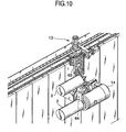
- FIGS. 9 through 19 are fragmentary perspective views illustrating respective operational facets of the changing unit 13.
- the control apparatus outputs a command signal to start the tool changing cycle.
- One of the three changing positions i.e., the first changing position P1, the second changing position P2 and the third changing position P3
- the control apparatus selects one position of the three changing positions which is closest to the tool 2 on the tool rest 14 which is presently machining the workpiece 3.
- the changing unit 13 moves to one of the three waiting positions (i.e., the first waiting position W1, the second waiting position W2 and the third waiting position W3) immediately above the shutter (i.e., the first shutter 44, the second shutter 45 or the third shutter 46) disposed above the selected changing position (step 103).
- the changing unit 13 then waits in the waiting position above the shutter (step 104). In FIG. 6 , the changing unit 13 is waiting with the arm 64 oriented horizontally.
- the changing unit 13 is waiting in the first waiting position W1 immediately above the first shutter 44 for changing the tools in the first changing position P1.
- the changing unit 13 is waiting in the second waiting position W2 immediately above the second shutter 45 for changing the tools in the second changing position P2.
- the changing unit 13 is waiting in the third waiting position W3 immediately above the third shutter 46 for changing the tools in the third changing position P3.
- the control apparatus outputs a tool change start signal (step 105).
- the tool rest 14 then interrupts the machining operation and moves to the changing position (i.e., to the position immediately below the shutter) closest to the machining position as indicated by the arrow K (step 106, FIGS. 7B through 7D ). At this time, the tool rest 14 should preferably move a shortest distance along an upward oblique path.
- the shutter is opened to provide a shutter opening in the splash guard 40 (step 107).
- the arm 64 of the changing unit 13 is swiveled to orient an idle tool gripper 68 downwardly ( FIG. 9 ) and the other tool gripper 68 carrying an unused tool 2 upwardly. Then, the arm 64 is lowered through the shutter opening to the changing position below (step 108).
- the tool 2 on the tool rest 14 is replaced in the changing position (step 109). Specifically, after the arm 64 is lowered, the lower idle tool gripper 68 grips the used tool 2 mounted on the tool rest 14 ( FIG. 10 ). The clamping and unclamping mechanism of the tool rest 14 is operated to unclamp the used tool 2 off the tool rest 14.
- the linearly driving servomotor 65 of the changing unit 13 is energized to move the changing unit 13 as a whole slightly to the left.
- the arm 64 is retracted along the central axis CL3 from the tool rest 14, pulling the used tool 2 from the tool rest 14 ( FIG. 11 ).
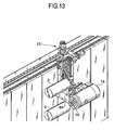
- the arm 64 is swiveled 180° to bring the used tool 2 into an upper position and to bring the unused tool 2 into a lower position, respectively ( FIGS. 12 and 13 ).
- the linearly driving servomotor 65 is energized to move the changing unit 13 as a whole slightly to the right.
- the unused tool 2 gripped by the lower tool gripper 68 of the arm 64 is now mounted on the tool spindle 15 of the tool rest 14 ( FIG. 14 ).
- the clamping and unclamping mechanism of the tool rest 14 is operated to clamp the unused tool 2 on the tool spindle 15 of the tool rest 14.
- the arm 64 is elevated (step 110, FIG. 15 ).
- the shutter is then closed, closing the machining area SP (step 111).
- the tool rest 14 returns to the machining position, and resumes machining the workpiece 3 with the new tool 2 (step 112).
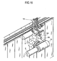
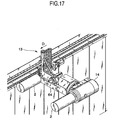
- the arm 64 is swiveled into a horizontal position ( FIG. 16 ), and then the changing unit 13 moves from the changing position to the magazine position Pm in the direction indicated by the arrow D (step 113, FIG. 17 ). After the changing unit 13 reaches the magazine position Pm ( FIG. 18 ), the arm 64 changes the tools on the magazine 12 (step 114, FIG. 19 ).
- the changing unit 13 swivels the arm 64 about the central axis CL3 and moves the arm 64 along the central axis CL3.
- the magazine 12 indexes the tool storage holder 52, which is storing a desired unused tool 2, or an idle tool storage holder 52 for receiving the used tool 2 to the magazine-side tool changing position Pa.
- the used tool 2 gripped by the tool gripper 68 of the arm 64 is stored on the idle tool storage holder 52. Thereafter, the unused tool 2 on the tool storage holder 52 is indexed to the magazine-side tool changing position Pa. In the magazine-side tool changing position Pa, the unused tool 2 on the tool storage holder 52 is gripped by the idle tool gripper 68 of the arm 64.
- step 114 the control apparatus determines whether a next tool changing cycle is to be carried out or not (step 115). If the next tool changing cycle is to be carried out, then control goes back to step 102. If the next tool changing cycle is not to be carried out, then the process of changing the tools is ended.
- step 112 the control apparatus determines whether the machining process is finished or not (step 116). If the machining process is not finished, then control goes back to step 102. If the machining process is finished, then the process of changing the tools is ended.
- both the changing unit 13 of the ATC 10 and the tool 2 mounted on the tool spindle 15 move to the changing position to change the tools.
- the ATC 10 has a plurality of changing positions (three changing positions in the illustrated embodiment) for changing the tools on the tool spindle 15.
- the changing unit 13 moves to the waiting position, which is close to the selected changing position, and waits in the waiting position. After the tool change start signal is output, therefore, the changing unit 13 and the tool spindle 15 are only required to move respective short distances up to the changing position.
- the illustrated machine tool 1 has the horizontally long machining area SP.
- the tool rest 14 has to move a long distance for changing the tools because of the horizontally long machining area SP.
- the tool rest 14 even though the machine tool 1 has the horizontally long machining area SP, the tool rest 14 only needs to move to the changing position closest to the machining position for changing the tools. Therefore, the distance that the tool rest 14 has to move may be short.
- the servomotors 65, 66, 67 and their drive force transmitting mechanisms may be relatively small in size. Consequently, the changing unit 13 may be relatively small in weight as a whole. As a result, the changing unit 13 can move and operate at a high speed, and the arm 64 can swivel at a high speed.
- the time required to change the tools on the tool spindle 15 is reduced, thus reducing the non-machining time of the machine tool 1.
- the ATC 10 as it is combined with the elongate machine tool 1 having the horizontally long machining area SP is highly advantageous in that it can greatly shorten the non-machining time of the machine tool 1.
- the ATC 10 according to the present embodiment was compared with an ATC according to the related art which is combined with an elongate machine tool having the same horizontally long machining area SP.
- the ATC according to the related art consumed 6.7 seconds for changing the tools when the tool rest 14 was machining the workpiece at a position closest to the changing position. However, when the tool rest 14 was machining the workpiece at a position remotest from the changing position, the ATC according to the related art consumed 27.3 seconds for changing the tools.
- the ATC 10 according to the present embodiment was capable of changing the tools in about 10 seconds at all times when the tool rest 14 was machining the workpiece at any position.
- the changing unit 13 moved horizontally at a speed of 70 m/min. along the Z-axis and moved vertically at a speed of 40 m/min. along the X-axis.
- the changing unit 13 is disposed outside of the splash guard 40 while it is not changing the tools. Therefore, when the changing unit 13 moves along the Z-axis, it does not interfere or contact with the tool rest 14. Except when the changing unit 13 is changing the tools on the tool spindle 15, the coolant and the chips are prevented by the splash guard 40 from being applied to and contaminating the changing unit 13. As a result, the changing unit 13 can change the tools highly accurately.
- the ATC according to the present invention is applicable to a lathe, a machining center, a turning center or a grinding machine, as well as a multi-axis turning center.
Abstract
Description
- The present invention relates to a machine tool having a tool magazine and an automatic machine changer for changing a tool.
- Machine tools with an automatic tool changer (hereinafter also referred to as "ATC") are disclosed in
U.S. patent 4,729,159 and Japanese laid-open patent publication No.59-227345 - The ATC disclosed in
U.S. patent 4,729,159 includes a feeder for gripping and feeding a tool, which travels outside the machining area of the machine tool. The machine tool disclosed in Japanese laid-open patent publication No.59-227345 - The ATC disclosed in
U.S. patent 4,729,159 has a predetermined tool changing position with respect to a tool rest. For changing tools, the tool rest has to move from a machining position to the tool changing position. As the tool rest needs to move a long distance to the tool changing position, it is time-consuming to replace the tool on the tool rest with another tool. Accordingly, the machining tool has a long non-machining time. - If the ATC disclosed in
U.S. patent 4,729,159 is incorporated in an elongate machine tool having a horizontally long machining area, the tool rest has to move a correspondingly long distance to the tool changing position. Therefore, there has been a demand for a technology for greatly reducing the time required to change tools. - In the machine tool disclosed in Japanese laid-open patent publication No.
59-227345 - Other ATCs according to the related art include a tool feeder disposed between a tool magazine and a tool changer arm. Tools are changed between the tool magazine and the tool changer arm via the tool feeder. However, these ATCs with the tool feeder are structurally complex in their entirety.
- Known from
JP 02 053542 A - It is an object of the present invention to provide a machine tool having an automatic tool changer in which a tool changing unit and a tool spindle move reduced distances, respectively, for changing tools thereby to shorten the non-machining time of the machine tool.
- A machine tool is provided in accordance with claim 1.
- The tool changing unit is controlled to wait in one position, of waiting positions, which is close to the selected changing position; and when a tool change start signal is output, the tool spindle may move to cause the tool to reach the selected changing position, and the tool changing unit may move and change the tools on the tool spindle in the selected changing position.
- Preferably, the machine tool has a long machining area which is elongate in a horizontal direction; the horizontally long machining area is covered with the splash guard; and the tool changing unit is disposed outside of the splash guard and is movable in the horizontal direction and is capable of waiting selectively in waiting positions near the shutters, respectively.
- Preferably, the shutters are placed on the ceiling panel of the splash guard along the horizontal direction; and the tool changing unit is movable above the ceiling panel of the splash guard in the horizontal direction along the shutters.
- Preferably, the tool changing unit comprises: a unit frame supported and guided by a traveling mechanism and actuated by a linearly driving servomotor to move in a displacing direction; a reciprocally movable member supported on the unit frame and actuated by a reciprocally driving servomotor to move reciprocally in a first direction perpendicular to the displacing direction; and an arm mounted on the reciprocally movable member and actuated to be swiveled by a swiveling servomotor, the arm having at least two tool grippers for detachably gripping the tool.
- Preferably, the machine tool is capable of machining the workpiece which is elongate; and when the long workpiece is machined with the tool, the tool changing unit transfers and changes the tool for successively using the tools stored in the tool magazine.
- Preferably, the machine tool comprises a multi-axis turning center including a headstock for rotatably supporting a workpiece spindle having a chuck for gripping the workpiece, and a tool rest having the tool spindle.
- Preferably, the tool changed by the tool changing unit comprises a cutter detachably mounted on a distal end of a boring bar mounted on the tool spindle of the tool rest; and the tool rest moves to cause the cutter to reach to the selected changing position and the tool changing unit is controlled to change the cutter on the boring bar mounted on the tool spindle.
- The machine tool having the automatic tool changer according to the present invention is constructed as described above. Since the tool changing unit and the tool mounted on the tool spindle move to a selected changing position, the distances which the tool changing unit and the tool spindle move for changing the tools are reduced thereby to shorten the non-machining time of the machine tool.
-
-
FIG. 1 is a perspective view of a machine tool according to the present invention; -
FIG. 2 is a perspective view showing structural details of the machine tool; -
FIG. 3 is a front elevational view showing structural details of the machine tool; -
FIG. 4 is a front elevational view showing structural details of the machine tool at the time it employs a boring bar; -
FIG. 5 is a side elevational view of the machine tool as from the right inFIG. 3 ; -
FIG. 6 is a fragmentary perspective view of an automatic tool changer of the machine tool; -
FIGS. 7A through 7D are schematic front elevational views illustrating a tool changing cycle; -
FIG. 8 is a flowchart of an operation sequence of a tool changing cycle; and -
FIGS. 9 through 19 are fragmentary perspective views illustrating an operational facet of a tool changing unit. - Like or corresponding parts are denoted by like or corresponding reference characters throughout views.
- A machine tool having an automatic tool changer according to the present invention comprises an automatic tool changer, a tool magazine for storing a plurality of tools, and a tool spindle for mounting a tool thereon and machining a workpiece with the tool. The automatic tool changer includes a movable tool changing unit (hereinafter referred to as "changing unit") for changing the tools.
- The changing unit moves between a magazine position and a changing position, and transfers the tools in the magazine position and the changing position. In the changing position, the changing unit replaces the tool on the tool spindle with another tool. In the magazine position, the changing unit replaces the tool thereon with another tool from the magazine.
- The machine tool has a plurality of changing positions. One of the changing positions is selected in advance for changing the tools next time. And then, the changing unit and the tool mounted on the tool spindle move to the selected changing position in which the changing unit replaces the tool on the tool spindle with another tool. Therefore, the changing unit and the tool spindle move relatively small distances, respectively, for changing the tools, thereby shortening the non-machining time of the machine tool.
- In a preferred embodiment of the present invention, the machine tool having the automatic tool changer comprises a multi-axis turning center. However, the machine tool may comprise a lathe having a tool spindle on a tool rest, a machining center having a tool spindle on a spindle head, a turning center or a grinding machine.
- A machine tool having an automatic tool changer according to a preferred embodiment of the present invention will be described below with reference to
FIGS. 1 through 19 . -
FIG. 1 is a perspective view of the machine tool.FIGS. 2 and3 are perspective and front elevational views, respectively, showing structural details of the machine tool.FIG. 4 is a front elevational view showing structural details of the machine tool at the time it employs a boring bar.FIG. 5 is a side elevational view of the machine tool as from the right inFIG. 3 .FIG. 6 is a fragmentary perspective view of an automatic tool changer of the machine tool.FIGS. 7A through 7D are schematic front elevational views illustrating a tool changing process. - As shown in
FIGS. 1 through 6 ,FIGS. 7A through 7D , the machine tool 1 according to the present embodiment comprises a multi-axis turning center. The machine tool 1 includes aheadstock 6, on which aworkpiece spindle 27 having achuck 5 for gripping aworkpiece 3 is rotatably supported, and atool rest 14 having atool spindle 15. - The machine tool 1 functions as a lathe for turning the
workpiece 3 with atool 2 and also as a machining center for cutting theworkpiece 3 with thetool 2. The machine tool 1 also functions as a boring machine for boring theworkpiece 3 with aboring bar 4. - The
tool 2 which is used by the machine tool 1 to turn or cut theworkpiece 3 is changed by an ATC (Automatic Tool Changer) 10. Thetool 2 is mounted on thetool spindle 15 on thetool rest 14 and machines theworkpiece 3 which is gripped by theheadstock 6. - The machine tool 1 comprises a
machine body 11, theATC 10 and atool magazine 12. TheATC 10 has a movable tool changing unit (hereinafter referred to as "changing unit") 13 for changing the tools. Themagazine 12 is capable of storing a plurality oftools 2. - When the machine tool 1 is used as a lathe, the
tool spindle 15 and thetool 2 do not rotate, but theworkpiece 3 rotates and is turned by thetool 2. - When the machine tool 1 is used as a machining center, the
tool 2 is rotated by thetool spindle 15 to cut theworkpiece 3. At this time, thetool rest 14 functions as a spindle head of the machining center. - The machine tool 1 is controlled by a control apparatus having an NC (Numerical Control) device and a PLC (Programmable Logic Controller). The control apparatus includes a
control console 16 disposed in a given position on the machine tool 1. - The machine tool 1 has a plurality of changing positions Px. The changing
unit 13 is movable between a magazine position Pm and the changing positions Px for transferring thetool 2. When the changingunit 13 is in one of the changing positions Px, the changingunit 13 changes thetool 2 on thetool spindle 15. When the changingunit 13 is in the magazine position Pm, the changingunit 13 changes thetool 2 on themagazine 12. - The changing positions Px include a first changing position P1, a second changing position P2 and a third changing position P3.
- The
ATC 10 changes the tools as follows: One (e.g., the first changing position P1) of the changing positions Px is selected in advance for changing the tools next time. The changing position (e.g., the first changing position P1) which is selected is closest to either the position of thetool 2 which is presently machining theworkpiece 3, or the position of thetool 2 which is scheduled to machine theworkpiece 3 next time. - Then, the changing
unit 13 and thetool 2, mounted on thetool spindle 15, move to the selected changing position (e.g., the first changing position P1) for changing thetools 2 in the selected changing position. When the changingunit 13 and thetool 2 mounted on thetool spindle 15 reach the selected changing position, the changingunit 13 replaces thetool 2 with another tool. As a result, the distances which the changingunit 13 and thetool spindle 15 move for changing the tools are reduced, and hence the changingunit 13 replaces thetool 2 with another tool in a reduced period of time. The non-machining time of the machine tool 1 is thus shortened. - The
machine body 11 includes abed 17 disposed on the floor and a pair ofcolumns 18 vertically mounted on the floor. Thecolumns 18 are horizontally spaced from other and disposed on respective longitudinal ends of thebed 17. Thebed 17 and thecolumns 18 jointly provide a base of themachine body 11. Themachine body 11 also includes abeam 19 extending horizontally between and supported by thecolumns 18. - The
columns 18 and thebeam 19 jointly provide a double-column frame which extends horizontally. The machine tool 1 has an X-axis, a Y-axis and a Z-axis which extend along vertical, transverse, and longitudinal directions, respectively, of the machine tool 1. Across slide 20 comprises a pair of horizontally spacedvertical members 21, an upper lateral member (not shown) and a lowerlateral member 22 which are joined together into a rectangular frame. Thecross slide 20 is horizontally movable along the Z-axis. Thecross slide 20 has lower and upper ends movably supported respectively by thebed 17 and thebeam 19. - A
saddle 23 is movably supported on thecross slide 20 for vertical movement along the X-axis. Thetool rest 14 is mounted on a front surface of thesaddle 23. Thetool 2 is detachably mounted on thetool spindle 15 of thetool rest 14. - While the machine tool 1 operates in the turning process, the
tool 2 is supported to be nonrotatable on thetool rest 14. While the machine tool 1 operates in the cutting process, thetool 2 is rotated by thetool rest 14. Thetool rest 14 is angularly movable about a central axis CL1 oriented along the Y-axis in the direction indicated by the arrow B, and can also be indexed to a desired angular position. - The
tool rest 14 has a clamping and unclamping mechanism (not shown) for selectively clamping and unclamping thetool 2 mounted on thetool spindle 15. - The
machine body 11 supports thereon Z-axis servomotors cross slide 20 along the Z-axis. - The Z-axis ball screws 26 have ends coupled to the Z-
axis servomotors axis servomotors axis servomotors cross slide 20 moves along the Z-axis while being supported and guided by the Z-axis guide rails. The Z-axis servomotors cross slide 20 can move in one direction and the other along the Z-axis. - The
cross slide 20 supports thereonX-axis servomotors 30, X-axis ball screws 31, andX-axis guide rails 32 for moving thesaddle 23 along the X-axis. The X-axis ball screws 31 have ends coupled to theX-axis servomotors 30 and are rotatable about their own axes by theX-axis servomotors 30. When the X-axis ball screws 31 are rotated about their own axes by theX-axis servomotors 30, thesaddle 23 moves along the X-axis while being supported and guided by the X-axis guide rails 32. TheX-axis servomotors 30 are reversible motors so that thesaddle 23 can move in one direction and the other along the X-axis. - The
chuck 5 is detachably mounted on the distal end of theworkpiece spindle 27 which is rotatably supported on theheadstock 6. Theworkpiece 3, which is gripped by thechuck 5, can be rotated by theworkpiece spindle 27 about a central axis CL2 oriented along the Z-axis. - For cutting the
workpiece 3 with thetool 2 in the form of a rotating tool, theheadstock 6 can be controlled to cause theworkpiece spindle 27 to index theworkpiece 3 to a given angular position. - The machine tool 1 is an elongate machine tool having a horizontally long machining area SP extending along the Z-axis. The machine tool 1 is suitable for machining the
workpiece 3 which has a large length in the range from 1,000 mm to 6,000 mm, for example. - For the machine tool 1 to machine the
long workpiece 3, themagazine 12 stores a number oftools 2 therein, and the changingunit 13 transfers and changes thetools 2. The machine tool 1 machines thelong workpiece 3 with thetool 2. - The machining area SP is covered with a
splash guard 40 for preventing the coolant and chips from being scattered out. Thesplash guard 40 has a plurality ofdoors 41, 42 and 43 (seeFig. 1 ) which can be selectively opened and closed. - The
splash guard 40 also has a plurality ofshutters unit 13 to change the tools. Theshutters shutters first shutter 44, asecond shutter 45 and athird shutter 46 which are disposed respectively in ceiling panels of thedoors 41, 42 and 43. - When the
shutters unit 13 to move through the opening. When all theshutters splash guard 40. - When all the
shutters workpiece 3 to be machined in the machining area SP, thefirst shutter 44 is disposed immediately above the first changing position P1, thesecond shutter 45 is disposed immediately above the second changing position P2, and thethird shutter 46 is disposed immediately above the third changing position P3. - The changing
unit 13 is positioned outside of thesplash guard 40 and can move along the Z-axis. The changingunit 13 is controlled to wait in one position of waiting positions (e.g., a first waiting position W1, a second waiting position W2 and a third waiting position W3) immediately above therespective shutters - The three
shutters splash guard 40 along the horizontal direction (Z-axis direction). The changingunit 13, when it is positioned above the ceiling panels of thesplash guard 40 of the machine tool 1, can move along the Z-axis over theshutters - The changing
unit 13 can travel shortest linear distances in short times between themagazine 12 and the changing positions P1, P2 and P3. The changingunit 13 is moved by a travelingmechanism 50 extending linearly along the Z-axis on the upper end of themachine body 11. Thelinear traveling mechanism 50 is relatively simple in structure. The shutters may be provided on rear panels of the splash guard. - As shown in
Figs. 1 ,18 and19 , themagazine 12 for storing a plurality oftools 2 is attached to themachine body 11. Themagazine 12 is located in a position outside of thesplash guard 40 at a left end of themachine body 11. - The
magazine 12 comprises a plurality oftool storage holders 52 and a plurality oflink plates 53. Thetool storage holders 52 hold thetools 2 removably thereon. Thetool storage holders 52 and thelink plates 53 are endlessly joined together, and are actuated by amagazine actuator 54 to move along a tortuous path while traveling around sprockets which are rotatable clockwise and counterclockwise. - The
magazine 12 operates to deliver thetool storage holder 52 storing a desired tool 2 (e.g., an unused tool 2) or an idletool storage holder 52 for receiving a usedtool 2, to a magazine-side tool changing position Pa. - The
magazine 12 is disposed independently of themachine body 11, and does not move along the Z-axis. Themagazine 12 is thus capable ofmany tools 2. - The
magazine 12 may have a storage capacity large enough to store 100 to 400tools 2. According to the machine tool 1, it is capable of machining theelongate workpiece 3 with a number oftools 2. - If the
workpiece 3 is a turbine shaft made of a hard material, then thetool 2 which is used to machine theworkpiece 3 tends to wear quickly. Therefore, themagazine 12 needs to storemany tools 2 of the same kind, and themagazine 12 needs to successively supply thetools 2 to replace the usedtool 2 withunused tools 2. Themagazine 12 which storesmany tools 2 is effective to handle such a situation. - The
elongate workpiece 3 referred to above is often bored by theboring bar 4 shown inFig. 4 . In the boring process, theATC 10 replaces theboring bar 4 on thetool rest 14 with a newboring bar 4. Aboring bar 4 which is longer than other boring bars is referred to as a long boring bar. - A certain
boring bar 4 has a cutter (tip) 2a on its distal end which is replaceable with another cutter (tip) 2a. If such aboring bar 4 is used, then theATC 10 replaces thecutter 2a of theboring bar 4 mounted on thetool spindle 15 of thetool rest 4 with anothercutter 2a. - When only the
cutter 2a of theboring bar 4 is to be replaced with anothercutter 2a by the changingunit 13, the control apparatus outputs a tool change start signal. Thetool rest 14 then moves to cause thecutter 2a to reach to a selected one, of the first changing position P1, the second changing position P2 and the third changing position P3, which is immediately below the corresponding one of thefirst shutter 44, thesecond shutter 45 and thethird shutter 46. - The changing
unit 13, which has waited in one of the waiting positions, also is controlled to move to the selected changing position. The changingunit 13 then is controlled to replace thecutter 2a, of theboring cutter 4 mounted on thetool spindle 15, with anew cutter 2a. Consequently, theATC 10 can replace thecutter 2a mounted on the distal end of theboring bar 4, as well as thetool 2 which is directly mounted on thetool spindle 15. - According to the present invention, the machine tool 1 is capable of replacing the
cutter 2a mounted on the distal end of theboring bar 4, as well as thetool 2 which is directly mounted on thetool spindle 15, in addition to offering the advantages described above. Furthermore, the machine tool 1 is capable of replacing thecutter 2a on theboring bar 4 without being limited by the size and length of theboring bar 4. - As shown in
Figs. 1 through 8 , when theATC 10 is to change the tools, it selects one of the changing positions Px, which include the first changing position P1, the second changing position P2 and the third changing position P3, as a changing position (e.g., the third changing position P3) for changing the tools next time. The third changing position P3 is selected because it may be closest to the position where thetool 2 on thetool spindle 15 is presently machining theworkpiece 3. - Then, the changing
unit 13 waits in a waiting position (i.e., the third waiting position W3) which is close to the selected changing position (i.e., the third changing position P3). - Thereafter, the control apparatus outputs the tool change start signal and the
tool rest 14 moves to displace thetool 2 thereon to the selected changing position (i.e., the third changing position P3). In this manner, both the changingunit 13 and thetool 2 mounted on thetool spindle 15 move to the selected changing position (i.e., the third changing position P3). Thereafter, the changingunit 13 replaces thetool 2 mounted on thetool spindle 15 with anew tool 2 in the selected changing position (i.e., the third changing position P3). - As a result, the distances which the changing
unit 13 and thetool spindle 15 move for changing the tools are reduced, and hence the changingunit 13 replaces thetool 2 with anothertool 2 in a reduced period of time. The non-machining time of the machine tool 1 is thus shortened. - The traveling
mechanism 50 extending linearly along the Z-axis is disposed on the upper end of themachine body 11 behind the machining area SP. Thelinear traveling mechanism 50 serves to move the changingunit 13 along the Z-axis. - The traveling
mechanism 50 comprises a pair ofguide rails 60, extending along the Z-axis and spaced vertically from each other, and arack 61 disposed alongguide rails 60 parallel thereto and extending along the Z-axis. - The changing
unit 13 comprises aunit frame 62, a reciprocallymovable member 63 and anarm 64. - The
unit frame 62 is supported and guided by the traveling mechanism 50 (i.e., the guide rails 60) and is movable in displacing directions along the guide rails 60 (i.e., the Z-axis) by a linearly drivingservomotor 65. Theservomotor 65 is mounted on theunit frame 62 and has a drive shaft oriented downwardly. - The reciprocally
movable member 63 is supported on theunit frame 62. The reciprocallymovable member 63 is reciprocally movable in first directions (i.e., vertically along the X-axis) perpendicular to the moving directions by a reciprocally drivingservomotor 66. Theservomotor 66 is mounted on theunit frame 62 and has a drive shaft oriented horizontally to the left. - The
arm 64 has at least two tool grippers 68 (twotool grippers 68 in the present embodiment) for detachably gripping thetool 2. Thearm 64 is rotatably mounted on the reciprocallymovable member 63 and is actuated by a swivelingservomotor 67 to swivel around a central axis CL3. - When the swiveling
servomotor 67 is energized, thearm 64 swivels about the central axis CL3 in the direction indicated by the arrow H until it is oriented in a desired direction. The swivelingservomotor 67 may be energized to index anunused tool 2 gripped by one of thetool grippers 68 to a given angular position or to index one of thetool grippers 68 which carries no tool to a given angular position. - When the linearly driving
servomotor 65 is energized to move the changingunit 13 as a whole in one of the directions indicated by the arrow D, thearm 64 is also moved in a direction along the central axis CL3. - When the
arm 64 is thus swiveled about the central axis CL3 and is moved back and forth along the central axis CL3, thearm 64 can install anunused tool 2 on thetool spindle 15 or remove a usedtool 2 from thetool spindle 15. - The changing
unit 13 can change the tools on thetool spindle 15 in a changing position which is selected from the changing positions Px. - The changing
unit 13 can also directly change the tools on themagazine 12 in the magazine position Pm. Accordingly, theATC 10 is of a relatively simple structure as it does not have a tool feeder which has heretofore been provided between the magazine and a tool changing arm. - The linearly driving
servomotor 65 on theunit frame 62 has a pinion, not shown, on its drive shaft which is held in driving mesh with therack 61. When the linearly drivingservomotor 65 is energized, the changingunit 13 moves along the Z-axis in one of the directions indicated by the arrow D by the pinion and therack 61. - The reciprocally driving
servomotor 66 is mounted on theunit frame 62 with its drive shaft extending horizontally. Avertical rack 75 is mounted on the reciprocallymovable member 63. The reciprocally drivingservomotor 66 has apinion 76 on its drive shaft which is held in driving mesh with therack 75. - The reciprocally
movable member 63 has a frame supported and guided by theunit frame 62 for movement along the X-axis in the directions indicated by the arrow G. When the reciprocally drivingservomotor 66 is energized, the reciprocallymovable member 63 is vertically moved along the X-axis in one of the directions indicated by the arrow G by thepinion 76 and therack 75. - The swiveling
servomotor 67 is mounted on the reciprocallymovable member 63 with its drive shaft oriented horizontally along the Z-axis. The drive shaft of the swivelingservomotor 67 extends toward the magazine 12 (to the left inFIG. 3 ). The swivelingservomotor 67 can index thearm 64 to a desired angular position through aspeed reducer mechanism 69. - The changing
unit 13 transfers thetool 2 by traveling between the magazine position Pm and a selected one of the plural changing positions Px. - The changing
unit 13 changes the tools on thetool spindle 15 in the first changing position P1, the second changing position P2 or the third changing position P3. The changingunit 13 also changes the tools on themagazine 12 in the magazine position Pm. - The changing
unit 13 which is constructed as described above is simpler in structure and lighter in weight than conventional automatic tool changers. - A process of changing the
tools 2 with theATC 10 will be described below with reference toFIGS. 1 ,3 ,6 through 19 . -
FIG. 8 is a flowchart of an operation sequence of a tool changing cycle.FIGS. 9 through 19 are fragmentary perspective views illustrating respective operational facets of the changingunit 13. - It is assumed that the
workpiece 3 gripped by thechuck 5 of theheadstock 6 is being machined by thetool 2 mounted on the tool rest 14 (step 101,FIG. 7A ). - The control apparatus outputs a command signal to start the tool changing cycle. One of the three changing positions (i.e., the first changing position P1, the second changing position P2 and the third changing position P3) is selected in advance as a changing position for changing the tools next time, while the
workpiece 3 is being machined by thetool 2 mounted on the tool rest 14 (step 102). At this time, the control apparatus selects one position of the three changing positions which is closest to thetool 2 on thetool rest 14 which is presently machining theworkpiece 3. - The changing
unit 13 moves to one of the three waiting positions (i.e., the first waiting position W1, the second waiting position W2 and the third waiting position W3) immediately above the shutter (i.e., thefirst shutter 44, thesecond shutter 45 or the third shutter 46) disposed above the selected changing position (step 103). - The changing
unit 13 then waits in the waiting position above the shutter (step 104). InFIG. 6 , the changingunit 13 is waiting with thearm 64 oriented horizontally. - In
FIG. 7B , the changingunit 13 is waiting in the first waiting position W1 immediately above thefirst shutter 44 for changing the tools in the first changing position P1. InFIG. 7C , the changingunit 13 is waiting in the second waiting position W2 immediately above thesecond shutter 45 for changing the tools in the second changing position P2. InFIG. 7D , the changingunit 13 is waiting in the third waiting position W3 immediately above thethird shutter 46 for changing the tools in the third changing position P3. - While the
workpiece 3 is being machined by thetool 2 on thetool rest 14, theATC 10 decides to replace thetool 2, which has been used, with anotherunused tool 2. The control apparatus outputs a tool change start signal (step 105). - The
tool rest 14 then interrupts the machining operation and moves to the changing position (i.e., to the position immediately below the shutter) closest to the machining position as indicated by the arrow K (step 106,FIGS. 7B through 7D ). At this time, thetool rest 14 should preferably move a shortest distance along an upward oblique path. - At the same time that, or after, the
tool rest 14 is moved, the shutter is opened to provide a shutter opening in the splash guard 40 (step 107). - The
arm 64 of the changingunit 13 is swiveled to orient anidle tool gripper 68 downwardly (FIG. 9 ) and theother tool gripper 68 carrying anunused tool 2 upwardly. Then, thearm 64 is lowered through the shutter opening to the changing position below (step 108). - After the
arm 64 is lowered, thetool 2 on thetool rest 14 is replaced in the changing position (step 109). Specifically, after thearm 64 is lowered, the loweridle tool gripper 68 grips the usedtool 2 mounted on the tool rest 14 (FIG. 10 ). The clamping and unclamping mechanism of thetool rest 14 is operated to unclamp the usedtool 2 off thetool rest 14. - Then, the linearly driving
servomotor 65 of the changingunit 13 is energized to move the changingunit 13 as a whole slightly to the left. Thearm 64 is retracted along the central axis CL3 from thetool rest 14, pulling the usedtool 2 from the tool rest 14 (FIG. 11 ). - Then, the
arm 64 is swiveled 180° to bring the usedtool 2 into an upper position and to bring theunused tool 2 into a lower position, respectively (FIGS. 12 and13 ). - Then, the linearly driving
servomotor 65 is energized to move the changingunit 13 as a whole slightly to the right. Theunused tool 2 gripped by thelower tool gripper 68 of thearm 64 is now mounted on thetool spindle 15 of the tool rest 14 (FIG. 14 ). The clamping and unclamping mechanism of thetool rest 14 is operated to clamp theunused tool 2 on thetool spindle 15 of thetool rest 14. - After the
tools 2 are changed, thearm 64 is elevated (step 110,FIG. 15 ). The shutter is then closed, closing the machining area SP (step 111). Thereafter, thetool rest 14 returns to the machining position, and resumes machining theworkpiece 3 with the new tool 2 (step 112). - The
arm 64 is swiveled into a horizontal position (FIG. 16 ), and then the changingunit 13 moves from the changing position to the magazine position Pm in the direction indicated by the arrow D (step 113,FIG. 17 ). After the changingunit 13 reaches the magazine position Pm (FIG. 18 ), thearm 64 changes the tools on the magazine 12 (step 114,FIG. 19 ). - Specifically, the changing
unit 13 swivels thearm 64 about the central axis CL3 and moves thearm 64 along the central axis CL3. Themagazine 12 indexes thetool storage holder 52, which is storing a desiredunused tool 2, or an idletool storage holder 52 for receiving the usedtool 2 to the magazine-side tool changing position Pa. - Specifically, in the magazine-side tool changing position Pa, the used
tool 2 gripped by thetool gripper 68 of thearm 64 is stored on the idletool storage holder 52. Thereafter, theunused tool 2 on thetool storage holder 52 is indexed to the magazine-side tool changing position Pa. In the magazine-side tool changing position Pa, theunused tool 2 on thetool storage holder 52 is gripped by theidle tool gripper 68 of thearm 64. - After the
tools 2 are changed on the magazine 12 (step 114), the control apparatus determines whether a next tool changing cycle is to be carried out or not (step 115). If the next tool changing cycle is to be carried out, then control goes back tostep 102. If the next tool changing cycle is not to be carried out, then the process of changing the tools is ended. - After the
new tool 2 on thetool rest 14 has resumed machining the workpiece 3 (step 112), the control apparatus determines whether the machining process is finished or not (step 116). If the machining process is not finished, then control goes back tostep 102. If the machining process is finished, then the process of changing the tools is ended. - As described above, both the changing
unit 13 of theATC 10 and thetool 2 mounted on thetool spindle 15 move to the changing position to change the tools. TheATC 10 has a plurality of changing positions (three changing positions in the illustrated embodiment) for changing the tools on thetool spindle 15. - The changing
unit 13 moves to the waiting position, which is close to the selected changing position, and waits in the waiting position. After the tool change start signal is output, therefore, the changingunit 13 and thetool spindle 15 are only required to move respective short distances up to the changing position. - The illustrated machine tool 1 has the horizontally long machining area SP. Heretofore, the
tool rest 14 has to move a long distance for changing the tools because of the horizontally long machining area SP. - According to the present embodiment, even though the machine tool 1 has the horizontally long machining area SP, the
tool rest 14 only needs to move to the changing position closest to the machining position for changing the tools. Therefore, the distance that thetool rest 14 has to move may be short. - As the changing
unit 13 is of a simple structure, theservomotors unit 13 may be relatively small in weight as a whole. As a result, the changingunit 13 can move and operate at a high speed, and thearm 64 can swivel at a high speed. - The time required to change the tools on the
tool spindle 15 is reduced, thus reducing the non-machining time of the machine tool 1. TheATC 10 as it is combined with the elongate machine tool 1 having the horizontally long machining area SP is highly advantageous in that it can greatly shorten the non-machining time of the machine tool 1. - The
ATC 10 according to the present embodiment was compared with an ATC according to the related art which is combined with an elongate machine tool having the same horizontally long machining area SP. - The ATC according to the related art consumed 6.7 seconds for changing the tools when the
tool rest 14 was machining the workpiece at a position closest to the changing position. However, when thetool rest 14 was machining the workpiece at a position remotest from the changing position, the ATC according to the related art consumed 27.3 seconds for changing the tools. - It was confirmed that the
ATC 10 according to the present embodiment was capable of changing the tools in about 10 seconds at all times when thetool rest 14 was machining the workpiece at any position. In theATC 10 according to the present embodiment, the changingunit 13 moved horizontally at a speed of 70 m/min. along the Z-axis and moved vertically at a speed of 40 m/min. along the X-axis. - The changing
unit 13 is disposed outside of thesplash guard 40 while it is not changing the tools. Therefore, when the changingunit 13 moves along the Z-axis, it does not interfere or contact with thetool rest 14. Except when the changingunit 13 is changing the tools on thetool spindle 15, the coolant and the chips are prevented by thesplash guard 40 from being applied to and contaminating the changingunit 13. As a result, the changingunit 13 can change the tools highly accurately. - The ATC according to the present invention is applicable to a lathe, a machining center, a turning center or a grinding machine, as well as a multi-axis turning center.
- Although a certain preferred embodiment of the present invention has been shown and described in detail, it should be understood that various changes and modifications may be made therein without departing from the scope of the appended claims.
Claims (8)
- A machine tool comprising an automatic tool changer (10) having a movable tool changing unit (13) for changing tools, a tool magazine (12) for storing a plurality of tools (2), and a tool spindle (15) for mounting a tool (2) thereon and for machining a workpiece (3) with the mounted tool (2);
wherein said tool changing unit (13) is adapted to move between a magazine position (Pm) and a changing position (Px) to transfer the tool (2), change the tools on said tool spindle (15) in said changing position (Px), and change the tools on said tool magazine (12) in said magazine position (Pm),
said machine tool (1) has a plurality of changing positions (Px);
one of said changing positions (Px) is adapted to be selected in advance for changing the tools next time; and
said tool changing unit (13) and the tool (2) mounted on said tool spindle (15) are adapted to move to the selected changing position (Px) for changing the tools in the selected changing position (Px),
characterized in that
said tool magazine (12) is located in a position outside of a splash guard (40);
said splash guard (40) has a plurality of shutters (44, 45, 46) which are selectively opened and closed for allowing said tool changing unit (13) to change tools;
said magazine position (Pm) and the plurality of changing positions (Px) are located along a horizontal direction (Z-axis) in which said tool changing unit (13) is adapted to move;
the shutters (44, 45, 46) are positioned in alignment with said changing positions (Px), respectively;
said tool changing unit (13) is adapted to move above a ceiling panel of the splash guard (40) in the horizontal direction (Z-axis). - The machine tool according to claim 1, said tool changing unit (13) is adapted to be controlled to wait in one position, of waiting positions (W1, W2 and W3), which is close to the selected changing position (Px); and
when a tool change start signal is output, said tool spindle (15) is adapted to move to cause said tool (2) to reach the selected changing position (Px), and said tool changing unit (13) is adapted to move and change the tools on said tool spindle (15) in the selected changing position (Px). - The machine tool (1) according to claim 1,
wherein the machine tool (1) has a long machining area (SP) which is elongate in the horizontal direction (Z-axis);
said horizontally long machining area (SP) is covered with said splash guard (40); and
said tool changing unit (13) is disposed outside of said splash guard (40) and is movable in said horizontal direction (Z-axis) and is capable of waiting selectively in waiting positions (W1, W2 and W3) near said shutters (44, 45 and 46), respectively. - The machine tool (1) according to claim 3,
wherein said shutters (44, 45 and 46) are placed on the ceiling panel of said splash guard (40) along said horizontal direction (Z-axis); and
said tool changing unit (13) is movable in said horizontal direction (Z-axis) along said shutters (44, 45 and 46). - The machine tool (1) according to claim 1, wherein said tool changing unit (13) comprises:a unit frame (62) supported and guided by a traveling mechanism (50) and actuated by a linearly driving servomotor (65) to move in a displacing direction (Z-axis);a reciprocally movable member (63) supported on said unit frame (62) and actuated by a reciprocally driving servomotor (66) to move reciprocally in a first direction (X-axis) perpendicular to said displacing direction (Z-axis); andan arm (64) mounted on said reciprocally movable member (63) and actuated to be swiveled by a swiveling servomotor (67), said arm (64) having at least two tool grippers (68) for detachably gripping said tool (2).
- The machine tool (1) according to claim 1,
wherein said machine tool (1) is capable of machining said workpiece (3) which is elongate; and
when said long workpiece (3) is machined with said tool (2), said tool changing unit (13) transfers and changes said tool (2) for successively using said tools (2) stored in said tool magazine (12). - The machine tool (1) according to claim 1,
wherein said machine tool (1) comprises a multi-axis turning center including a headstock (6) for rotatably supporting a workpiece spindle (27) having a chuck (5) for gripping said workpiece (3), and a tool rest (14) having said tool spindle (15). - The machine tool (1) according to claim 7,
wherein said tool (2) changed by said tool changing unit (13) comprises a cutter (2a) detachably mounted on a distal end of a boring bar (4) mounted on said tool spindle (15) of said tool rest (14); and
said tool rest (14) moves to cause said cutter (2a) to reach to the selected changing position and said tool changing unit (13) is controlled to change said cutter (2a) on said boring bar (4) mounted on said tool spindle (15).
Applications Claiming Priority (1)
| Application Number | Priority Date | Filing Date | Title |
|---|---|---|---|
| JP2007203701A JP5026884B2 (en) | 2007-08-04 | 2007-08-04 | Machine tool with automatic tool changer |
Publications (2)
| Publication Number | Publication Date |
|---|---|
| EP2025449A1 EP2025449A1 (en) | 2009-02-18 |
| EP2025449B1 true EP2025449B1 (en) | 2011-06-15 |
Family
ID=39855302
Family Applications (1)
| Application Number | Title | Priority Date | Filing Date |
|---|---|---|---|
| EP08013829A Active EP2025449B1 (en) | 2007-08-04 | 2008-08-01 | Machine tool with automatic tool changer |
Country Status (4)
| Country | Link |
|---|---|
| US (1) | US8114000B2 (en) |
| EP (1) | EP2025449B1 (en) |
| JP (1) | JP5026884B2 (en) |
| AT (1) | ATE512754T1 (en) |
Cited By (2)
| Publication number | Priority date | Publication date | Assignee | Title |
|---|---|---|---|---|
| CN106312654A (en) * | 2015-06-30 | 2017-01-11 | 遵义林棣科技发展有限公司 | Additional type automatic control system for numerically controlled lathes |
| TWI614087B (en) * | 2015-09-07 | 2018-02-11 | Improved structure of ball milling cutter |
Families Citing this family (12)
| Publication number | Priority date | Publication date | Assignee | Title |
|---|---|---|---|---|
| KR200471002Y1 (en) | 2011-03-02 | 2014-01-28 | 코요 프레시젼 컴퍼니 리미티드 | A tool magazine and tool changer of machining center |
| JP5843452B2 (en) * | 2011-03-04 | 2016-01-13 | 富士機械製造株式会社 | Robot and workpiece machining system |
| KR101416386B1 (en) * | 2012-12-17 | 2014-07-08 | 현대자동차 주식회사 | Spindle jig and Auto pallet changable machining center having the same |
| JP6836143B2 (en) * | 2016-12-27 | 2021-02-24 | 株式会社ジェイテクト | Machine Tools |
| JP6687579B2 (en) * | 2017-10-24 | 2020-04-22 | ファナック株式会社 | Numerical control device |
| KR102347406B1 (en) * | 2018-01-03 | 2022-01-05 | 두산공작기계 주식회사 | Tool clamping device of machine tool |
| JP6680811B2 (en) * | 2018-01-26 | 2020-04-15 | ファナック株式会社 | Processing time prediction device |
| CN108907840A (en) * | 2018-09-30 | 2018-11-30 | 宁波天瑞精工机械有限公司 | A kind of automatic exchanging orientation device of planer-type milling machine |
| US20230191548A1 (en) * | 2020-03-23 | 2023-06-22 | Dn Solutions Co., Ltd. | Boring bar tool changer and boring bar tool changing method using same |
| JP7372457B2 (en) | 2020-04-24 | 2023-10-31 | Dmg森精機株式会社 | processing machinery |
| TWI792893B (en) * | 2022-01-26 | 2023-02-11 | 喬陞機器股份有限公司 | Pipe fittings feeding machine |
| CN116330021B (en) * | 2023-04-21 | 2024-01-30 | 冈田智能(江苏)股份有限公司 | Two-handed tool changing device and tool changing method thereof |
Family Cites Families (19)
| Publication number | Priority date | Publication date | Assignee | Title |
|---|---|---|---|---|
| JPS511865B1 (en) * | 1968-09-30 | 1976-01-21 | ||
| GB1364645A (en) * | 1970-08-28 | 1974-08-29 | Olivetti & Co Spa | Machine tool with automatic toolchange |
| US4221043A (en) * | 1979-03-05 | 1980-09-09 | Kearney & Trecker Corporation | Automatic tool changer for multiple spindle machine tool |
| JPS59227345A (en) | 1983-06-09 | 1984-12-20 | Yamazaki Mazak Corp | Compound machining lathe |
| JPS6234741A (en) * | 1985-08-06 | 1987-02-14 | Mazda Motor Corp | Tool replacing device in machining center |
| DE3532924A1 (en) * | 1985-09-14 | 1987-03-26 | Gildemeister Ag | TOOL CHANGE DEVICE |
| JPS62131368U (en) | 1986-02-14 | 1987-08-19 | ||
| JPH0729255B2 (en) * | 1987-09-10 | 1995-04-05 | ファナック株式会社 | NC data creation method for turning |
| JPH01264732A (en) * | 1988-04-12 | 1989-10-23 | Kitamura Mach Co Ltd | Machine tool |
| JPH0688189B2 (en) | 1988-08-11 | 1994-11-09 | 日立精機株式会社 | Tool change method of automatic tool changer |
| JPH04122543A (en) * | 1990-09-10 | 1992-04-23 | Mitsubishi Electric Corp | Numerical control device and tool replacing position changing method |
| JP3310134B2 (en) * | 1995-05-24 | 2002-07-29 | オークマ株式会社 | Machine Tools |
| FR2748225B1 (en) * | 1996-05-03 | 1998-07-31 | Renault Automation | DEVICE FOR STORING TOOLS OF A MACHINE TOOL |
| DE19937238A1 (en) | 1999-08-06 | 2001-02-15 | Heyligenstaedt Gmbh & Co Kg I | Lathe and method for changing tools of such a lathe |
| US6352496B1 (en) * | 2000-01-28 | 2002-03-05 | Imta Manufacturing Technology & Automation Company | High-speed milling machine with rotary table |
| JP2003170324A (en) * | 2001-12-04 | 2003-06-17 | Mitsubishi Materials Corp | Tool positioning structure of automatic tool exchanger, and tool positioning method |
| JP4632344B2 (en) * | 2003-12-18 | 2011-02-16 | 株式会社森精機製作所 | Machine tool with a boring bar magazine |
| AT504171B1 (en) * | 2006-09-14 | 2009-09-15 | Josef Ing Muser | METHOD FOR LOADING AND UNLOADING A TOOLING MACHINE WITH TOOLS |
| US7264581B1 (en) * | 2007-01-08 | 2007-09-04 | Ding Koan Machinery Co., Ltd | Machining center with a relay tool exchange device |
-
2007
- 2007-08-04 JP JP2007203701A patent/JP5026884B2/en active Active
-
2008
- 2008-08-01 AT AT08013829T patent/ATE512754T1/en not_active IP Right Cessation
- 2008-08-01 EP EP08013829A patent/EP2025449B1/en active Active
- 2008-08-01 US US12/184,582 patent/US8114000B2/en active Active
Cited By (2)
| Publication number | Priority date | Publication date | Assignee | Title |
|---|---|---|---|---|
| CN106312654A (en) * | 2015-06-30 | 2017-01-11 | 遵义林棣科技发展有限公司 | Additional type automatic control system for numerically controlled lathes |
| TWI614087B (en) * | 2015-09-07 | 2018-02-11 | Improved structure of ball milling cutter |
Also Published As
| Publication number | Publication date |
|---|---|
| ATE512754T1 (en) | 2011-07-15 |
| EP2025449A1 (en) | 2009-02-18 |
| JP2009034803A (en) | 2009-02-19 |
| US20090036282A1 (en) | 2009-02-05 |
| US8114000B2 (en) | 2012-02-14 |
| JP5026884B2 (en) | 2012-09-19 |
Similar Documents
| Publication | Publication Date | Title |
|---|---|---|
| EP2025449B1 (en) | Machine tool with automatic tool changer | |
| US8549964B2 (en) | Machine tool for turning operations | |
| EP2058082B1 (en) | Machine tool | |
| US6920679B2 (en) | Machine tool | |
| JP2009113170A5 (en) | ||
| JP2003136352A (en) | Milling cutter, and hole boring machining center | |
| US20060207397A1 (en) | Lathe, and Machining System Equipped with the Lathe | |
| WO2017033510A1 (en) | Machine tool | |
| JP2005334920A (en) | Tool-changing magazine in laser beam machine | |
| KR102004471B1 (en) | Multi type tool changer and multi-spindle type machining center with the same | |
| KR102057727B1 (en) | Machining center with multi-spindle | |
| JP2009178804A (en) | Machine tool with boring bar magazine, and boring bar magazine | |
| US4837918A (en) | Machine tool assembly | |
| JP3985998B2 (en) | Machine tools for complex machining | |
| JP6570632B2 (en) | Machine Tools | |
| JP3165158U (en) | Machine tool with a boring bar magazine | |
| JP7108148B1 (en) | Bar feeders and machine tools | |
| US20230158622A1 (en) | Processing machine | |
| JP5219604B2 (en) | Machine tool pallet changer | |
| JP2000084787A (en) | Machine tool equipped with two tool spindle heads | |
| JP3865330B2 (en) | Tool conveying method for matrix type tool magazine and matrix type tool magazine | |
| JPH0890303A (en) | Numerically controlled automatic lathe | |
| JPH0550303A (en) | Bar machining lathe | |
| JPH07178603A (en) | Nc loader in nc lathe |
Legal Events
| Date | Code | Title | Description |
|---|---|---|---|
| PUAI | Public reference made under article 153(3) epc to a published international application that has entered the european phase |
Free format text: ORIGINAL CODE: 0009012 |
|
| AK | Designated contracting states |
Kind code of ref document: A1 Designated state(s): AT BE BG CH CY CZ DE DK EE ES FI FR GB GR HR HU IE IS IT LI LT LU LV MC MT NL NO PL PT RO SE SI SK TR |
|
| AX | Request for extension of the european patent |
Extension state: AL BA MK RS |
|
| 17P | Request for examination filed |
Effective date: 20090731 |
|
| 17Q | First examination report despatched |
Effective date: 20090831 |
|
| AKX | Designation fees paid |
Designated state(s): AT DE |
|
| GRAP | Despatch of communication of intention to grant a patent |
Free format text: ORIGINAL CODE: EPIDOSNIGR1 |
|
| RIN1 | Information on inventor provided before grant (corrected) |
Inventor name: MATSUSHITA, HIROTO Inventor name: YASUDA, HIROSHI |
|
| RIN1 | Information on inventor provided before grant (corrected) |
Inventor name: YASUDA, HIROSHI Inventor name: MATSUSHITA, HIROTO |
|
| GRAS | Grant fee paid |
Free format text: ORIGINAL CODE: EPIDOSNIGR3 |
|
| GRAA | (expected) grant |
Free format text: ORIGINAL CODE: 0009210 |
|
| AK | Designated contracting states |
Kind code of ref document: B1 Designated state(s): AT DE |
|
| REG | Reference to a national code |
Ref country code: DE Ref legal event code: R096 Ref document number: 602008007542 Country of ref document: DE Effective date: 20110804 |
|
| PG25 | Lapsed in a contracting state [announced via postgrant information from national office to epo] |
Ref country code: AT Free format text: LAPSE BECAUSE OF FAILURE TO SUBMIT A TRANSLATION OF THE DESCRIPTION OR TO PAY THE FEE WITHIN THE PRESCRIBED TIME-LIMIT Effective date: 20110615 |
|
| PLBE | No opposition filed within time limit |
Free format text: ORIGINAL CODE: 0009261 |
|
| STAA | Information on the status of an ep patent application or granted ep patent |
Free format text: STATUS: NO OPPOSITION FILED WITHIN TIME LIMIT |
|
| 26N | No opposition filed |
Effective date: 20120316 |
|
| REG | Reference to a national code |
Ref country code: DE Ref legal event code: R097 Ref document number: 602008007542 Country of ref document: DE Effective date: 20120316 |
|
| PGFP | Annual fee paid to national office [announced via postgrant information from national office to epo] |
Ref country code: DE Payment date: 20230821 Year of fee payment: 16 |