EP2025432A1 - Method for creating steel long products through strand casting and rolling - Google Patents
Method for creating steel long products through strand casting and rolling Download PDFInfo
- Publication number
- EP2025432A1 EP2025432A1 EP07014841A EP07014841A EP2025432A1 EP 2025432 A1 EP2025432 A1 EP 2025432A1 EP 07014841 A EP07014841 A EP 07014841A EP 07014841 A EP07014841 A EP 07014841A EP 2025432 A1 EP2025432 A1 EP 2025432A1
- Authority
- EP
- European Patent Office
- Prior art keywords
- mold
- strand
- casting
- steel
- strands
- Prior art date
- Legal status (The legal status is an assumption and is not a legal conclusion. Google has not performed a legal analysis and makes no representation as to the accuracy of the status listed.)
- Granted
Links
- 238000009749 continuous casting Methods 0.000 title claims abstract description 38
- 238000005096 rolling process Methods 0.000 title claims abstract description 34
- 229910000831 Steel Inorganic materials 0.000 title claims abstract description 23
- 239000010959 steel Substances 0.000 title claims abstract description 23
- 238000000034 method Methods 0.000 title claims abstract description 22
- 230000002093 peripheral effect Effects 0.000 claims abstract description 16
- 238000005266 casting Methods 0.000 claims abstract description 15
- 238000009826 distribution Methods 0.000 claims abstract description 9
- 238000003303 reheating Methods 0.000 claims abstract description 6
- 238000001816 cooling Methods 0.000 claims abstract description 3
- 239000000155 melt Substances 0.000 claims abstract description 3
- 239000007788 liquid Substances 0.000 claims abstract 3
- 238000004519 manufacturing process Methods 0.000 claims description 3
- 230000003014 reinforcing effect Effects 0.000 claims 1
- 238000010438 heat treatment Methods 0.000 abstract description 6
- 230000033228 biological regulation Effects 0.000 abstract description 5
- 230000001105 regulatory effect Effects 0.000 abstract 2
- 239000000161 steel melt Substances 0.000 abstract 1
- 230000001419 dependent effect Effects 0.000 description 1
- 238000011161 development Methods 0.000 description 1
- 230000018109 developmental process Effects 0.000 description 1
- 230000002349 favourable effect Effects 0.000 description 1
- 238000009434 installation Methods 0.000 description 1
- 238000000465 moulding Methods 0.000 description 1
- 230000000717 retained effect Effects 0.000 description 1
- XLYOFNOQVPJJNP-UHFFFAOYSA-N water Substances O XLYOFNOQVPJJNP-UHFFFAOYSA-N 0.000 description 1
Images
Classifications
-
- B—PERFORMING OPERATIONS; TRANSPORTING
- B22—CASTING; POWDER METALLURGY
- B22D—CASTING OF METALS; CASTING OF OTHER SUBSTANCES BY THE SAME PROCESSES OR DEVICES
- B22D11/00—Continuous casting of metals, i.e. casting in indefinite lengths
- B22D11/04—Continuous casting of metals, i.e. casting in indefinite lengths into open-ended moulds
- B22D11/041—Continuous casting of metals, i.e. casting in indefinite lengths into open-ended moulds for vertical casting
-
- B—PERFORMING OPERATIONS; TRANSPORTING
- B22—CASTING; POWDER METALLURGY
- B22D—CASTING OF METALS; CASTING OF OTHER SUBSTANCES BY THE SAME PROCESSES OR DEVICES
- B22D11/00—Continuous casting of metals, i.e. casting in indefinite lengths
- B22D11/04—Continuous casting of metals, i.e. casting in indefinite lengths into open-ended moulds
- B22D11/0406—Moulds with special profile
-
- B—PERFORMING OPERATIONS; TRANSPORTING
- B21—MECHANICAL METAL-WORKING WITHOUT ESSENTIALLY REMOVING MATERIAL; PUNCHING METAL
- B21B—ROLLING OF METAL
- B21B1/00—Metal-rolling methods or mills for making semi-finished products of solid or profiled cross-section; Sequence of operations in milling trains; Layout of rolling-mill plant, e.g. grouping of stands; Succession of passes or of sectional pass alternations
- B21B1/46—Metal-rolling methods or mills for making semi-finished products of solid or profiled cross-section; Sequence of operations in milling trains; Layout of rolling-mill plant, e.g. grouping of stands; Succession of passes or of sectional pass alternations for rolling metal immediately subsequent to continuous casting
- B21B1/463—Metal-rolling methods or mills for making semi-finished products of solid or profiled cross-section; Sequence of operations in milling trains; Layout of rolling-mill plant, e.g. grouping of stands; Succession of passes or of sectional pass alternations for rolling metal immediately subsequent to continuous casting in a continuous process, i.e. the cast not being cut before rolling
Definitions
- the invention relates to a process for the production of steel long products according to the preamble of claim 1 and a continuous casting mold for the process.
- the minimum intake speed at the inlet of the rolling train should under no circumstances be less than 4.2 m / min in order not to thermally overload the rollers due to the long contact time with the rolling stock.
- the billet at the inlet of the mill train should have a suitable temperature for rolling both at the surface and in the core (1150-1250 ° C).
- the surface temperature should be distributed as homogeneously as possible.
- the present invention has for its object to propose a method that allows a simpler plant configuration and a more cost-effective operation.
- the billet and Vorblockstrlinde generated by rapid continuous casting can be fed directly to a rolling mill without additional heating.
- the mold cavity of this Stranggiesskokillen has at the inlet end of the mold along a circumferential line of its cross section at least two peripheral portions which each limit a cross-sectional enlargement of the mold cavity relative to the corresponding peripheral portions of the mold cavity cross-section at the strand outlet end of the mold in the form of protrusions.
- the arc heights of the bulges are reduced in strand running direction such that deforms during molding in the mold cavity strand shell during passage through the mold, and thereby a uniform cooling and shell growth or a homogeneous temperature distribution along the strand circumference is ensured, creating a direct introduction in the rolling mill permitting high continuous casting speed is possible.
- the temperature conditions in G fauxstrang at the outlet of the casting plant for the introduction into the rolling mill suitable, if necessary, a temperature regulation can be provided, but no heating is necessary.
- the circumferential line of an approximately circular mold cavity cross section on the pouring side is subdivided into at least three substantially equal circumferential sections and each of these peripheral sections exhibits on the pouring side the cross sectional enlargement of the mold cavity as a bulge.
- the arc heights of the bulges are reduced on all peripheral sections in the strand direction at least along a partial length of the mold cavity.
- the circumferential line of a polygonal, preferably quadrangular cavity section on the pouring side between all corners on peripheral portions with cross-sectional enlargements of the mold cavity in the form of protrusions and the heights of the bulges decrease in size on all peripheral portions in strand direction at least along a partial length of the mold cavity.
- the inventive method for producing long-steel products in which the billets and Vorblockstrlinde generated in the continuous casting mold directly - fed without additional heating - a rolling train and there rolled into long products, allows a simple system configuration and a cost-effective operation.
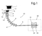
- Fig.1 schematically shows the structure of a known continuous casting 10 with a ladle 1, an intermediate vessel 2 (Tundish), cooled with water mold 3, and a Strandumlenk noticed 6 for the strand 5, which pulled by means of rollers 6 'and bent into the horizontal. Thereafter, the strand 5 according to the invention is fed directly to a rolling train 20, which has a plurality of rolling units 21 with rolling rolls 22, which is not shown in detail since such rolling trains 20 or rolling mills are known.
- a mold cavity 3 'of this mold 3 has at the inlet end of the mold along a circumferential line of its cross section at least two peripheral portions, each having a cross-sectional enlargement of the mold cavity 3' relative to the corresponding peripheral portions of Form cavity gap at the strand outlet end of the mold 3 in the form of bulges limit, which is not illustrated in detail.
- the continuous casting speed of the strand 5 is advantageously at least 4.2 m / min in order not to exceed the permissible contact time between the strand and the rolls at the inlet of the rolling train and thereby not to shorten their durability unreasonable.
- the temperature conditions at the outlet of the continuous casting plant 10 for the introduction into the rolling train are precisely adapted so that the rolling of the strand can be carried out in an optimal manner. At most, however, a passive temperature compensation, without external energy supply can be made.
- the mold cavity cross section of the continuous casting mold is essentially formed as a four-round format.
- This four-round format is based on a square or rectangle, but it is provided in the corners with relatively large radii. Strand exit side, these radii in the corner regions are advantageously approximately 20 to 40 mm at a length or width of the mold cavity cross-section of 120 to 180 mm.
- an edge rounding of about 25 mm and the continuous casting speed of at least 5.2 m / min and correspondingly in a four-round format of 180 mm an edge rounding of about 40 mm and casting speed of at least 4.2 m / min could be provided.
- a sliding closure 15 is provided for the purpose of accurate inflow control of the molten steel to be poured into the mold.
- a regulation of the fill level of the melt in the mold 3 is carried out as a function of the inlet speed in the first stand (so-called master-slave operation), for a control device 13 and a level gauge 14 are provided in the mold 3. This regulation is intended to achieve an approximately constant filling level in the mold.
- a refractory dip tube attached to the inflow control element and protruding into the mold is advantageous, so that the bath surface in the mold is as smooth as possible.
- the cast billet strands form essentially a four-round format and their fillet is selected according to the format such that, at a sufficiently high casting speed, a strand is produced having a temperature distribution required for rolling, which can be directly rolled without any active reheating, i. the cast strands are fed endlessly to the rolling train without being cut into pieces.
Abstract
Description
Die Erfindung betrifft ein Verfahren zur Erzeugung von Stahl-Langprodukten gemäss dem Oberbegriff des Anspruches 1 sowie eine Stranggiesskokille für das Verfahren.The invention relates to a process for the production of steel long products according to the preamble of claim 1 and a continuous casting mold for the process.
Es ist bekannt, den beim Stranggiessen erzeugten Giessstrang zu einzelnen Knüppeln oder Vorblöcken zu schneiden, auf Raumtemperatur abzukühlen und dann in einem Walzwerk wiedererwärmt zu Stahlstab, Draht und anderen Stahl-Langprodukten zu verwalzen.It is known to cut the cast strand produced by continuous casting into individual billets or billets, to cool it to room temperature and then rewarmed in a rolling mill to steel rod, wire and other steel long products.
Bekannt ist auch die gegossenen Knüppeln heiss (ca. 600°C) in den Walzwerksofen zwecks Nacherwärmung vor dem anschliessenden Verwalzen einzusetzen.
Um Energie zu sparen und das Ausbringen zu erhöhen, wird seit langem nach Lösungen gesucht, wie man eine Stranggiessanlage und eine Walzstrasse, vorzugsweise eine Giessader und eine Walzader, direkt verbinden könnte.Also known is the cast billets hot (about 600 ° C) in the rolling mill furnace for the purpose of reheating before the subsequent rolling use.
In order to save energy and increase the output, solutions have long been sought, as one could directly connect a continuous casting and a rolling mill, preferably a casting ladder and a Walzader.
Dabei stellen die unterschiedlichen Durchsätze, Geschwindigkeiten und Temperaturen sowie Temperaturverteilungen (Strangguss-Oberfläche/Zentrum) am Auslauf der Giessanlage und am Einlauf der Walzstrasse die Hauptprobleme dar.The different flow rates, speeds and temperatures as well as temperature distributions (continuous casting surface / center) at the outlet of the casting plant and at the inlet of the rolling train represent the main problems.
Die minimale Einzugsgeschwindigkeit am Einlauf der Walzstrasse sollte keinesfalls unter 4.2 m/min liegen um die Walzen infolge der langen Kontaktzeit mit dem Walzgut nicht thermisch zu überlasten. Ausserdem soll der Knüppel am Einlauf der Walzstrasse eine für das Walzen geeignete Temperatur sowohl an der Oberfläche als auch im Kern (1150-1250°C) aufweisen. Insbesondere sollte die Oberflächentemperatur möglichst homogen verteilt sein.The minimum intake speed at the inlet of the rolling train should under no circumstances be less than 4.2 m / min in order not to thermally overload the rollers due to the long contact time with the rolling stock. In addition, the billet at the inlet of the mill train should have a suitable temperature for rolling both at the surface and in the core (1150-1250 ° C). In particular, the surface temperature should be distributed as homogeneously as possible.
Aus der
Der vorliegenden Erfindung liegt die Aufgabe zugrunde, ein Verfahren vorzuschlagen, das eine einfachere Anlagekonfiguration und einen kostengünstigeren Betrieb ermöglicht.The present invention has for its object to propose a method that allows a simpler plant configuration and a more cost-effective operation.
Diese Aufgabe wird erfindungsgemäss durch ein Verfahren mit den Merkmalen des Anspruches 1 gelöst.This object is achieved according to the invention by a method having the features of claim 1.
Bevorzugte Weitergestaltungen des erfindungsgemässen Verfahrens sowie bevorzugte Stranggiesskokillen für das Verfahren bilden den Gegenstand der abhängigen Ansprüche.Preferred further developments of the method according to the invention as well as preferred continuous casting molds for the method form the subject matter of the dependent claims.
Es wurde überraschenderweise festgestellt, dass bei Verwendung von Stranggiesskokillen, wie sie aus der
Es ist heute praktisch möglich, im Querschnitt vierkantige Stränge im Formatbereich 120-130 mm mit einer Geschwindigkeit von ca. 6m/min zu Giessen. Bei Kokillen-Querschnittsformen nach der
Bei einer besonders bevorzugten Ausführungsform einer Stranggiesskokille für das erfindungsgemässe Verfahren ist die Umfangslinie eines etwa runden Formhohlraumquerschnittes auf der Eingiessseite in mindestens drei im wesentlichen gleich grosse Umfangsabschnitte unterteilt und jeder dieser Umfangsabschnitte weist auf der Eingiessseite die Querschnittsvergrösserung des Formhohlraumes als Ausbuchtung auf. Die Bogenhöhen der Ausbuchtungen verkleinern sich auf allen Umfangsabschnitten in Stranglaufrichtung mindestens entlang einer Teillänge des Formhohlraumes.In a particularly preferred embodiment of a continuous casting mold for the process according to the invention, the circumferential line of an approximately circular mold cavity cross section on the pouring side is subdivided into at least three substantially equal circumferential sections and each of these peripheral sections exhibits on the pouring side the cross sectional enlargement of the mold cavity as a bulge. The arc heights of the bulges are reduced on all peripheral sections in the strand direction at least along a partial length of the mold cavity.
Bei einer weiteren vorteilhaften Ausführungsform einer Stranggiesskokille für das erfindungsgemässe Verfahren weist die Umfangslinie eines polygonalen, vorzugsweise viereckigen Formhohlraumquerschnittes auf der Eingiessseite zwischen allen Ecken Umfangsabschnitte mit Querschnittsvergrösserungen des Formhohlraumes in der Form von Ausbuchtungen auf und die Bogenhöhen der Ausbuchtungen verkleinern sich auf allen Umfangsabschnitten in Stranglaufrichtung mindestens entlang einer Teillänge des Formhohlraumes.In a further advantageous embodiment of a continuous casting mold for the method according to the invention, the circumferential line of a polygonal, preferably quadrangular cavity section on the pouring side between all corners on peripheral portions with cross-sectional enlargements of the mold cavity in the form of protrusions and the heights of the bulges decrease in size on all peripheral portions in strand direction at least along a partial length of the mold cavity.
Das erfindungsgemässe Verfahren zur Erzeugung von Stahl-Langprodukten, bei welchem die in der Stranggiesskokille erzeugten Knüppel- und Vorblockstränge unmittelbar - ohne zusätzliches Aufheizen - einer Walzstrasse zugeführt und dort zu Langprodukten gewalzt werden, ermöglicht eine einfache Anlagekonfiguration sowie einen kostengünstigen Betrieb.The inventive method for producing long-steel products, in which the billets and Vorblockstränge generated in the continuous casting mold directly - fed without additional heating - a rolling train and there rolled into long products, allows a simple system configuration and a cost-effective operation.
Die Erfindung wird nachfolgend anhand der Zeichnung näher erläutert. Es zeigt rein schematisch:
- Fig. 1
- eine schematische Darstellung einer nach dem erfindungsgemässen Verfahren arbeitende Stranggiessanlage mit einer Walzstrasse.
- Fig. 1
- a schematic representation of a working according to the inventive continuous casting plant with a rolling train.
Ein Formhohlraum 3' dieser Kokille 3 weist am eingiessseitigen Ende der Kokille entlang einer Umfangslinie seines Querschnittes mindestens zwei Umfangsabschnitte auf, die je eine Querschnittsvergrösserung des Formhohlraumes 3' gegenüber den entsprechenden Umfangsabschnitten des Formhohlraumquerschnittes am strangaustrittseitigen Ende der Kokille 3 in der Form von Ausbuchtungen begrenzen, was nicht näher veranschaulicht ist.A mold cavity 3 'of this
Die Stranggiessgeschwindigkeit des Stranges 5 beträgt vorteilhaft mindestens 4.2 m/min, um die zulässige Kontaktzeit zwischen Strang und der Walzen am Einlauf der Walzstrasse nicht zu überschreiten und dadurch deren Haltbarkeit nicht unzumutbar zu verkürzen.The continuous casting speed of the
Die Temperaturverhältnisse am Auslauf der Stranggiessanlage 10 für die Einführung in die Walzstrasse sind genau angepasst, damit das Walzen des Stranges in optimaler Weise erfolgen kann. Allenfalls kann jedoch ein passiver Temperaturausgleich, ohne Fremdenergiezufuhr vorgenommen werden.The temperature conditions at the outlet of the
Der Formhohlraumquerschnitt der Stranggiesskokille ist im Wesentlichen als Vierrundformat gebildet. Dieses Vierrundformat basiert auf einem Quadrat oder Rechteck, wobei es in den Eckbereichen jedoch mit relativ grossen Radien versehen ist. Strangaustrittseitig betragen diese Radien in den Eckbereichen vorteilhaft annähernd 20 bis 40 mm bei einer Länge bzw. Breite des Formhohlraumquerschnittes von 120 bis 180 mm.The mold cavity cross section of the continuous casting mold is essentially formed as a four-round format. This four-round format is based on a square or rectangle, but it is provided in the corners with relatively large radii. Strand exit side, these radii in the corner regions are advantageously approximately 20 to 40 mm at a length or width of the mold cavity cross-section of 120 to 180 mm.
Zum Beispiel könnte bei einem Vierrundformat 120 mm eine Kantenverrundung von ca. 25 mm sowie die Stranggiessgeschwindigkeit mind. 5.2 m/min und entsprechend bei einem Vierrundformat 180 mm eine Kantenverrundung von ca. 40 mm sowie Giessgeschwindigkeit von mindestens 4.2 m/min vorgesehen sein.For example, in the case of a four-round format 120 mm, an edge rounding of about 25 mm and the continuous casting speed of at least 5.2 m / min and correspondingly in a four-round format of 180 mm an edge rounding of about 40 mm and casting speed of at least 4.2 m / min could be provided.
Beim Ausguss 11 des oberhalb der Kokille 3 befindlichen Zwischengefässes 2 ist ein an sich herkömmliches Regelorgan, vorzugsweise ein Schiebeverschluss 15 zwecks genauer Zuflussregelung der abzugiessenden Stahlschmelze in die Kokille vorgesehen. Eine Regelung der Füllstandshöhe der Schmelze in der Kokille 3 erfolgt in Abhängigkeit der Einlaufgeschwindigkeit im ersten Walzgerüst (sog. Master-Slave Betrieb), dafür eine Regeleinrichtung 13 und ein Füllstandsmessgerät 14 bei der Kokille 3 vorgesehen sind. Mit dieser Regelung soll eine annähernd konstante Füllhöhe in der Kokille erzielt werden. Vorteilhaft ist zudem ein am Zuflussregelorgan befestigtes und in die Kokille ragendes feuerfestes Tauchrohr vorhanden, damit sich eine möglichst ruhige Badoberfläche in der Kokille ergibt.When
Die gegossenen Knüppelstränge bilden im Wesentlichen ein Vierrund-Format und deren Verrundung entsprechend dem Format so gewählt wird, dass bei ausreichend grosser Giessgeschwindigkeit ein Strang mit für das Walzen erforderlicher Temperaturverteilung produziert wird, welches ohne jeglicher aktiver Nacherwärmung direkt verwalzt werden kann, d.h. die gegossenen Stränge werden endlos, ohne in Stücke geteilt zu werden, der Walzstrasse zugeführt.The cast billet strands form essentially a four-round format and their fillet is selected according to the format such that, at a sufficiently high casting speed, a strand is produced having a temperature distribution required for rolling, which can be directly rolled without any active reheating, i. the cast strands are fed endlessly to the rolling train without being cut into pieces.
Claims (12)
die gegossenen Knüppelstränge direkt einer Walzstrasse im Wesentlichen ohne Nacherwärmung zugeführt werden.Process for the production of steel long products by continuous casting of steel into billet strands and subsequent rolling of these billet strands and billet strands to the long products, such as bar steel or wire, wherein the liquid steel is poured into a continuous casting mold, characterized in that
the cast billet strands are fed directly to a rolling train substantially without reheating.
Priority Applications (11)
| Application Number | Priority Date | Filing Date | Title |
|---|---|---|---|
| EP07014841.6A EP2025432B2 (en) | 2007-07-27 | 2007-07-27 | Method for creating steel long products through strand casting and rolling |
| KR1020107000773A KR20100038195A (en) | 2007-07-27 | 2008-07-17 | Process for producing steel long products by continuous casting and rolling |
| RU2010107172/02A RU2484921C2 (en) | 2007-07-27 | 2008-07-17 | Method of producing long-length rolled stock by continuous casting and rolling |
| PCT/EP2008/005864 WO2009015782A2 (en) | 2007-07-27 | 2008-07-17 | Process for producing steel long products by continuous casting and rolling |
| US12/670,445 US20100276111A1 (en) | 2007-07-27 | 2008-07-17 | Process for Producing Steel Long Products by Continuous Casting and Rolling |
| CN200880100820.0A CN102105244B (en) | 2007-07-27 | 2008-07-17 | By the method for continuous casting and rolling for the production of steel long products |
| BRPI0814203A BRPI0814203A8 (en) | 2007-07-27 | 2008-07-17 | process for producing long steel products through continuous casting and rolling |
| CA2694755A CA2694755C (en) | 2007-07-27 | 2008-07-17 | Process for producing steel long products by continuous casting and rolling |
| JP2010517302A JP2011504141A (en) | 2007-07-27 | 2008-07-17 | Method for producing long steel products by continuous casting and rolling |
| ZA2010/00216A ZA201000216B (en) | 2007-07-27 | 2010-01-12 | Process for producing steel long products by continuous casting and rolling |
| JP2013166381A JP5632942B2 (en) | 2007-07-27 | 2013-08-09 | Method for producing long steel products by continuous casting and rolling |
Applications Claiming Priority (1)
| Application Number | Priority Date | Filing Date | Title |
|---|---|---|---|
| EP07014841.6A EP2025432B2 (en) | 2007-07-27 | 2007-07-27 | Method for creating steel long products through strand casting and rolling |
Publications (3)
| Publication Number | Publication Date |
|---|---|
| EP2025432A1 true EP2025432A1 (en) | 2009-02-18 |
| EP2025432B1 EP2025432B1 (en) | 2014-03-19 |
| EP2025432B2 EP2025432B2 (en) | 2017-08-30 |
Family
ID=38754538
Family Applications (1)
| Application Number | Title | Priority Date | Filing Date |
|---|---|---|---|
| EP07014841.6A Active EP2025432B2 (en) | 2007-07-27 | 2007-07-27 | Method for creating steel long products through strand casting and rolling |
Country Status (10)
| Country | Link |
|---|---|
| US (1) | US20100276111A1 (en) |
| EP (1) | EP2025432B2 (en) |
| JP (2) | JP2011504141A (en) |
| KR (1) | KR20100038195A (en) |
| CN (1) | CN102105244B (en) |
| BR (1) | BRPI0814203A8 (en) |
| CA (1) | CA2694755C (en) |
| RU (1) | RU2484921C2 (en) |
| WO (1) | WO2009015782A2 (en) |
| ZA (1) | ZA201000216B (en) |
Families Citing this family (4)
| Publication number | Priority date | Publication date | Assignee | Title |
|---|---|---|---|---|
| CN103480647B (en) * | 2013-09-18 | 2016-03-23 | 陕西钢铁集团有限公司 | A kind of device and production method thereof of producing reinforcing bar without heating low temperature Direct Rolling small billet |
| CN104923752B (en) * | 2015-07-08 | 2017-04-26 | 南京工业大学 | Titanium or titanium alloy continuous casting technology and equipment |
| AT519277A1 (en) * | 2016-11-03 | 2018-05-15 | Primetals Technologies Austria GmbH | Casting and rolling plant |
| CN114932146A (en) * | 2022-06-30 | 2022-08-23 | 浙江青山钢铁有限公司 | Rolling method of super duplex stainless steel wire |
Citations (4)
| Publication number | Priority date | Publication date | Assignee | Title |
|---|---|---|---|---|
| DE1816849A1 (en) * | 1968-12-24 | 1970-07-02 | Demag Ag | Method and system for casting and rolling from the casting heat of metal, in particular steel bars |
| JPS6448609A (en) * | 1987-08-19 | 1989-02-23 | Hitachi Ltd | Method for controlling speed |
| EP0498296A2 (en) * | 1991-02-06 | 1992-08-12 | Concast Standard Ag | Mould for continuous casting of metals, especially of steel |
| EP1466682A1 (en) * | 2003-03-28 | 2004-10-13 | SMS Demag Aktiengesellschaft | Continuous casting equipment with a continuous casting mould for casting of molten meltal, in particular steel |
Family Cites Families (37)
| Publication number | Priority date | Publication date | Assignee | Title |
|---|---|---|---|---|
| US3349834A (en) * | 1965-09-21 | 1967-10-31 | United States Steel Corp | Dual-control for controlling the liquid level in a continuous casting mold |
| CH541756A (en) * | 1972-01-05 | 1973-09-15 | Sistag | Slider |
| JPS5137031A (en) * | 1974-09-18 | 1976-03-29 | Mitsubishi Heavy Ind Ltd | RENZOKUCHU ZOATSUENHOHO |
| JPS5514133A (en) * | 1978-07-14 | 1980-01-31 | Toshiba Corp | Producing apparatus of steel bar product |
| CH639468A5 (en) * | 1979-04-05 | 1983-11-15 | Sidler Stalder Sistag Maschine | EXPLOSION PROTECTION SHUT-OFF DEVICE WITH FUEL-OPERATED CLOSING ORGAN. |
| JPS5747509A (en) † | 1980-09-05 | 1982-03-18 | Kikai Syst Shinko Kyokai | Controlling method for speed of direct rolling mill united with continuous casting machine |
| CH652180A5 (en) * | 1981-10-29 | 1985-10-31 | Sistag | FLAT SLIDE. |
| GB2142122B (en) * | 1983-06-24 | 1986-05-08 | Sistag | Gate valve |
| CH666733A5 (en) * | 1984-12-19 | 1988-08-15 | Sistag | FLAT SLIDE. |
| SE464619B (en) * | 1985-09-13 | 1991-05-27 | Olsson Ag Erik | SETTING AND PLANTING FOR STRENGTHENING WITH HORIZONTAL OR SLEEPING COCKLE |
| CH670872A5 (en) * | 1986-07-07 | 1989-07-14 | Sistag | |
| DE59300864D1 (en) * | 1992-03-05 | 1995-12-07 | Concast Standard Ag | METHOD FOR CONTINUOUSLY CASTING METAL, ESPECIALLY STEEL IN BLOCK AND CUT BLOCKS. |
| CH686457A5 (en) * | 1992-08-11 | 1996-03-29 | Sistag | Plate slide. |
| US5297578A (en) * | 1992-08-14 | 1994-03-29 | Tillotson, Ltd. | Automatic shutoff valve |
| JP2856305B2 (en) * | 1993-09-22 | 1999-02-10 | 日新製鋼株式会社 | Control method of molten steel level in mold in continuous casting |
| JP2989737B2 (en) † | 1993-11-25 | 1999-12-13 | 勝彦 山田 | Continuous casting and continuous casting / rolling of steel |
| DE59506676D1 (en) * | 1994-07-25 | 1999-09-30 | Concast Standard Ag | Straggiesskokille for a double-T pre-profile |
| DE19639299C2 (en) * | 1996-09-25 | 2001-02-22 | Sms Demag Ag | Device for producing a polygonal or profile format in a continuous caster |
| AUPO591697A0 (en) * | 1997-03-27 | 1997-04-24 | Bhp Steel (Jla) Pty Limited | Casting metal strip |
| GB2325971B (en) * | 1997-05-29 | 2001-04-04 | Sistag Absperrtechnik | A driving device for a shut-off device in a pipe-line |
| ATE227617T1 (en) † | 1997-12-24 | 2002-11-15 | Europa Metalli Spa | CONTINUOUS CASTING MILL |
| JP3298523B2 (en) * | 1998-10-29 | 2002-07-02 | 住友金属工業株式会社 | Metal surface level control method for continuous casting |
| DE10027324C2 (en) * | 1999-06-07 | 2003-04-10 | Sms Demag Ag | Process for casting a metallic strand and system therefor |
| JP3649143B2 (en) * | 2001-04-03 | 2005-05-18 | 住友金属工業株式会社 | Continuous casting method |
| DE50301920D1 (en) † | 2002-02-22 | 2006-01-19 | Sms Demag Ag | METHOD FOR THE CONTINUOUS CASTING AND IMMEDIATE FORMING OF METAL, PARTICULARLY A CAST STREAM OF STEEL MATERIALS |
| CH695792A5 (en) * | 2002-09-25 | 2006-08-31 | Sistag Absperrtechnik | Shut-off device for a pipeline. |
| ES2242119T3 (en) * | 2003-04-16 | 2005-11-01 | Concast Ag | TUBULAR LINGOTERA FOR CONTINUOUS COLADA. |
| DE50309338D1 (en) † | 2003-12-27 | 2008-04-17 | Concast Holding Ag | Process for continuous casting of billets and billets and mold cavity of a continuous casting mold |
| SI1676658T1 (en) * | 2004-12-29 | 2008-10-31 | Concast Ag | Continuous steel casting plant for billets and blooms |
| ME01742B (en) † | 2005-07-19 | 2010-10-31 | Giovanni Arvedi | Process and related plant for manufacturing steel long products without interruption |
| EP1815925B1 (en) * | 2005-12-24 | 2011-07-27 | Concast Ag | Method and apparatus for the continuous casting of double-T-bleam blanks |
| ATE552930T1 (en) * | 2007-06-04 | 2012-04-15 | Concast Ag | MOLD FOR CONTINUOUS CASTING BLOCKS, SLAMS OR BILLETS |
| JP5012255B2 (en) * | 2007-06-27 | 2012-08-29 | 住友金属工業株式会社 | Continuous casting method for small section slabs |
| BRPI0819722A2 (en) * | 2008-01-14 | 2019-09-24 | Sms Concast Ag | continuous casting system particularly for long steel products and a method for continuous casting |
| CH700412B1 (en) * | 2009-02-05 | 2018-02-28 | Sistag Ag | Gate valve, in particular for shutting off a media-carrying line. |
| CH701449A2 (en) * | 2009-07-02 | 2011-01-14 | Sistag Absperrtechnik | Slide valves, in particular leading to the closing of a media line. |
| US7946556B1 (en) * | 2010-08-16 | 2011-05-24 | Sistag Ag Absperrtechnik | Resilient seat seal for a valve |
-
2007
- 2007-07-27 EP EP07014841.6A patent/EP2025432B2/en active Active
-
2008
- 2008-07-17 CN CN200880100820.0A patent/CN102105244B/en not_active Expired - Fee Related
- 2008-07-17 KR KR1020107000773A patent/KR20100038195A/en active IP Right Grant
- 2008-07-17 WO PCT/EP2008/005864 patent/WO2009015782A2/en active Application Filing
- 2008-07-17 RU RU2010107172/02A patent/RU2484921C2/en not_active IP Right Cessation
- 2008-07-17 JP JP2010517302A patent/JP2011504141A/en active Pending
- 2008-07-17 CA CA2694755A patent/CA2694755C/en not_active Expired - Fee Related
- 2008-07-17 US US12/670,445 patent/US20100276111A1/en not_active Abandoned
- 2008-07-17 BR BRPI0814203A patent/BRPI0814203A8/en not_active Application Discontinuation
-
2010
- 2010-01-12 ZA ZA2010/00216A patent/ZA201000216B/en unknown
-
2013
- 2013-08-09 JP JP2013166381A patent/JP5632942B2/en not_active Expired - Fee Related
Patent Citations (5)
| Publication number | Priority date | Publication date | Assignee | Title |
|---|---|---|---|---|
| DE1816849A1 (en) * | 1968-12-24 | 1970-07-02 | Demag Ag | Method and system for casting and rolling from the casting heat of metal, in particular steel bars |
| JPS6448609A (en) * | 1987-08-19 | 1989-02-23 | Hitachi Ltd | Method for controlling speed |
| EP0498296A2 (en) * | 1991-02-06 | 1992-08-12 | Concast Standard Ag | Mould for continuous casting of metals, especially of steel |
| EP1466682A1 (en) * | 2003-03-28 | 2004-10-13 | SMS Demag Aktiengesellschaft | Continuous casting equipment with a continuous casting mould for casting of molten meltal, in particular steel |
| EP1839776A2 (en) * | 2003-03-28 | 2007-10-03 | SMS Demag AG | Strand casting device with a strand casting die for casting liquid metals, in particular for steel grades |
Non-Patent Citations (1)
| Title |
|---|
| LIU JIAN ET AL: "Operational Success of a 5-Strand High Speed Convex Technology Billet Caster for SBQ Steels at Shagang Steel, CHINA", INTERNET ARTICLE, 14 May 2001 (2001-05-14) - 16 May 2001 (2001-05-16), Singapore, pages 1 - 9, XP002461363, Retrieved from the Internet <URL:http://www.concast-standard.com/pdf/Caster_SEAISI%20May01.pdf> * |
Also Published As
| Publication number | Publication date |
|---|---|
| CA2694755A1 (en) | 2009-02-05 |
| EP2025432B2 (en) | 2017-08-30 |
| RU2484921C2 (en) | 2013-06-20 |
| JP2013223887A (en) | 2013-10-31 |
| WO2009015782A3 (en) | 2009-05-28 |
| CN102105244B (en) | 2015-09-09 |
| JP5632942B2 (en) | 2014-11-26 |
| WO2009015782A2 (en) | 2009-02-05 |
| KR20100038195A (en) | 2010-04-13 |
| BRPI0814203A8 (en) | 2018-12-18 |
| CA2694755C (en) | 2015-02-24 |
| ZA201000216B (en) | 2011-04-28 |
| RU2010107172A (en) | 2011-09-10 |
| BRPI0814203A2 (en) | 2015-01-27 |
| US20100276111A1 (en) | 2010-11-04 |
| EP2025432B1 (en) | 2014-03-19 |
| JP2011504141A (en) | 2011-02-03 |
| CN102105244A (en) | 2011-06-22 |
Similar Documents
| Publication | Publication Date | Title |
|---|---|---|
| DE3627991C2 (en) | ||
| EP2349612B2 (en) | Method and continuous casting plant for manufacturing thick slabs | |
| WO2009141207A1 (en) | Method and continuous casting plant for producing thick slabs | |
| EP2025432B1 (en) | Method for creating steel long products through strand casting and rolling | |
| DE4403049C1 (en) | Continuous caster and method for producing thin slabs | |
| EP3016762B1 (en) | Cast-rolling installation and method for producing metallic rolled stock | |
| DE10357363B4 (en) | Method and plant for casting and immediately subsequent rolling of casting strands of metal, in particular of steel materials, preferably thin strands | |
| WO2002034432A1 (en) | Method and device for continuous casting and subsequent forming of a steel billet, especially a billet in the form of an ingot or a preliminary section | |
| EP3441157B1 (en) | Method and apparatus for cintinuous casting of a metallic product | |
| EP1132161B1 (en) | Process for continuous casting slabs, especially thin slabs | |
| DE2420347B2 (en) | DEVICE FOR THE MANUFACTURING OF COPPER WIRE | |
| EP3705202B1 (en) | Conversion of a continuous casting plant for billet or bloom strands | |
| DE60204895T2 (en) | METHOD FOR CONTINUOUS STEEL PRE-BLOCKING | |
| EP1585605A1 (en) | Method and device for producing continuously cast steel slabs | |
| DE3440235C2 (en) | Method and device for continuous strip casting of metals, in particular steel | |
| DE19639299A1 (en) | Method and device for producing a polygonal or profile format in a continuous caster | |
| DE2913024A1 (en) | PROCESS FOR COOLING AN OSCILLATING CONTINUOUS STEEL COLLAR | |
| DE10122118A1 (en) | Method and device for the continuous casting of blocks, slabs and thin slabs | |
| EP3519124B1 (en) | Method for multiple casting of metal strengths | |
| EP0160835B1 (en) | Method of and installation for continuous casting of metal into a mould with cooled walls being in circular movement | |
| DE2015033A1 (en) | Molten metal feed for continuous casting of sections | |
| AT525563A4 (en) | DRY CASTING IN A COMBINED CASTING-ROLLING PLANT | |
| DE1458013C (en) | Method and device for the continuous production of a profiled steel strand 4nm Concast 4G, which can be divided into several partial strands, Zurich (Switzerland) | |
| DE2735421A1 (en) | METHOD AND DEVICE FOR CONTINUOUS CASTING OF A STEEL STRAND | |
| DE2510673A1 (en) | Continuous casting mould - shaped to prolong contact between steel strand and mould walls and increase heat transfer |
Legal Events
| Date | Code | Title | Description |
|---|---|---|---|
| PUAI | Public reference made under article 153(3) epc to a published international application that has entered the european phase |
Free format text: ORIGINAL CODE: 0009012 |
|
| AK | Designated contracting states |
Kind code of ref document: A1 Designated state(s): AT BE BG CH CY CZ DE DK EE ES FI FR GB GR HU IE IS IT LI LT LU LV MC MT NL PL PT RO SE SI SK TR |
|
| AX | Request for extension of the european patent |
Extension state: AL BA HR MK RS |
|
| 17P | Request for examination filed |
Effective date: 20090813 |
|
| 17Q | First examination report despatched |
Effective date: 20090915 |
|
| AKX | Designation fees paid |
Designated state(s): AT BE BG CH CY CZ DE DK EE ES FI FR GB GR HU IE IS IT LI LT LU LV MC MT NL PL PT RO SE SI SK TR |
|
| APBK | Appeal reference recorded |
Free format text: ORIGINAL CODE: EPIDOSNREFNE |
|
| APBN | Date of receipt of notice of appeal recorded |
Free format text: ORIGINAL CODE: EPIDOSNNOA2E |
|
| APBR | Date of receipt of statement of grounds of appeal recorded |
Free format text: ORIGINAL CODE: EPIDOSNNOA3E |
|
| APAF | Appeal reference modified |
Free format text: ORIGINAL CODE: EPIDOSCREFNE |
|
| APBT | Appeal procedure closed |
Free format text: ORIGINAL CODE: EPIDOSNNOA9E |
|
| GRAP | Despatch of communication of intention to grant a patent |
Free format text: ORIGINAL CODE: EPIDOSNIGR1 |
|
| INTG | Intention to grant announced |
Effective date: 20131113 |
|
| GRAS | Grant fee paid |
Free format text: ORIGINAL CODE: EPIDOSNIGR3 |
|
| GRAA | (expected) grant |
Free format text: ORIGINAL CODE: 0009210 |
|
| AK | Designated contracting states |
Kind code of ref document: B1 Designated state(s): AT BE BG CH CY CZ DE DK EE ES FI FR GB GR HU IE IS IT LI LT LU LV MC MT NL PL PT RO SE SI SK TR |
|
| REG | Reference to a national code |
Ref country code: GB Ref legal event code: FG4D Free format text: NOT ENGLISH |
|
| REG | Reference to a national code |
Ref country code: CH Ref legal event code: EP |
|
| REG | Reference to a national code |
Ref country code: IE Ref legal event code: FG4D Free format text: LANGUAGE OF EP DOCUMENT: GERMAN |
|
| REG | Reference to a national code |
Ref country code: AT Ref legal event code: REF Ref document number: 657300 Country of ref document: AT Kind code of ref document: T Effective date: 20140415 |
|
| REG | Reference to a national code |
Ref country code: DE Ref legal event code: R096 Ref document number: 502007012871 Country of ref document: DE Effective date: 20140430 |
|
| REG | Reference to a national code |
Ref country code: CH Ref legal event code: NV Representative=s name: LUCHS AND PARTNER PATENTANWAELTE, CH |
|
| PG25 | Lapsed in a contracting state [announced via postgrant information from national office to epo] |
Ref country code: LT Free format text: LAPSE BECAUSE OF FAILURE TO SUBMIT A TRANSLATION OF THE DESCRIPTION OR TO PAY THE FEE WITHIN THE PRESCRIBED TIME-LIMIT Effective date: 20140319 |
|
| REG | Reference to a national code |
Ref country code: NL Ref legal event code: VDEP Effective date: 20140319 |
|
| REG | Reference to a national code |
Ref country code: LT Ref legal event code: MG4D |
|
| PG25 | Lapsed in a contracting state [announced via postgrant information from national office to epo] |
Ref country code: FI Free format text: LAPSE BECAUSE OF FAILURE TO SUBMIT A TRANSLATION OF THE DESCRIPTION OR TO PAY THE FEE WITHIN THE PRESCRIBED TIME-LIMIT Effective date: 20140319 Ref country code: CY Free format text: LAPSE BECAUSE OF FAILURE TO SUBMIT A TRANSLATION OF THE DESCRIPTION OR TO PAY THE FEE WITHIN THE PRESCRIBED TIME-LIMIT Effective date: 20140319 Ref country code: SE Free format text: LAPSE BECAUSE OF FAILURE TO SUBMIT A TRANSLATION OF THE DESCRIPTION OR TO PAY THE FEE WITHIN THE PRESCRIBED TIME-LIMIT Effective date: 20140319 |
|
| PG25 | Lapsed in a contracting state [announced via postgrant information from national office to epo] |
Ref country code: LV Free format text: LAPSE BECAUSE OF FAILURE TO SUBMIT A TRANSLATION OF THE DESCRIPTION OR TO PAY THE FEE WITHIN THE PRESCRIBED TIME-LIMIT Effective date: 20140319 |
|
| PG25 | Lapsed in a contracting state [announced via postgrant information from national office to epo] |
Ref country code: IS Free format text: LAPSE BECAUSE OF FAILURE TO SUBMIT A TRANSLATION OF THE DESCRIPTION OR TO PAY THE FEE WITHIN THE PRESCRIBED TIME-LIMIT Effective date: 20140719 Ref country code: EE Free format text: LAPSE BECAUSE OF FAILURE TO SUBMIT A TRANSLATION OF THE DESCRIPTION OR TO PAY THE FEE WITHIN THE PRESCRIBED TIME-LIMIT Effective date: 20140319 Ref country code: CZ Free format text: LAPSE BECAUSE OF FAILURE TO SUBMIT A TRANSLATION OF THE DESCRIPTION OR TO PAY THE FEE WITHIN THE PRESCRIBED TIME-LIMIT Effective date: 20140319 Ref country code: BG Free format text: LAPSE BECAUSE OF FAILURE TO SUBMIT A TRANSLATION OF THE DESCRIPTION OR TO PAY THE FEE WITHIN THE PRESCRIBED TIME-LIMIT Effective date: 20140619 Ref country code: RO Free format text: LAPSE BECAUSE OF FAILURE TO SUBMIT A TRANSLATION OF THE DESCRIPTION OR TO PAY THE FEE WITHIN THE PRESCRIBED TIME-LIMIT Effective date: 20140319 Ref country code: NL Free format text: LAPSE BECAUSE OF FAILURE TO SUBMIT A TRANSLATION OF THE DESCRIPTION OR TO PAY THE FEE WITHIN THE PRESCRIBED TIME-LIMIT Effective date: 20140319 |
|
| PG25 | Lapsed in a contracting state [announced via postgrant information from national office to epo] |
Ref country code: SK Free format text: LAPSE BECAUSE OF FAILURE TO SUBMIT A TRANSLATION OF THE DESCRIPTION OR TO PAY THE FEE WITHIN THE PRESCRIBED TIME-LIMIT Effective date: 20140319 Ref country code: PL Free format text: LAPSE BECAUSE OF FAILURE TO SUBMIT A TRANSLATION OF THE DESCRIPTION OR TO PAY THE FEE WITHIN THE PRESCRIBED TIME-LIMIT Effective date: 20140319 Ref country code: ES Free format text: LAPSE BECAUSE OF FAILURE TO SUBMIT A TRANSLATION OF THE DESCRIPTION OR TO PAY THE FEE WITHIN THE PRESCRIBED TIME-LIMIT Effective date: 20140319 |
|
| REG | Reference to a national code |
Ref country code: DE Ref legal event code: R026 Ref document number: 502007012871 Country of ref document: DE |
|
| PLBI | Opposition filed |
Free format text: ORIGINAL CODE: 0009260 |
|
| PG25 | Lapsed in a contracting state [announced via postgrant information from national office to epo] |
Ref country code: PT Free format text: LAPSE BECAUSE OF FAILURE TO SUBMIT A TRANSLATION OF THE DESCRIPTION OR TO PAY THE FEE WITHIN THE PRESCRIBED TIME-LIMIT Effective date: 20140721 |
|
| PLAX | Notice of opposition and request to file observation + time limit sent |
Free format text: ORIGINAL CODE: EPIDOSNOBS2 |
|
| 26 | Opposition filed |
Opponent name: SIEMENS VAI METALS TECHNOLOGIES GMBH Effective date: 20141218 |
|
| PG25 | Lapsed in a contracting state [announced via postgrant information from national office to epo] |
Ref country code: DK Free format text: LAPSE BECAUSE OF FAILURE TO SUBMIT A TRANSLATION OF THE DESCRIPTION OR TO PAY THE FEE WITHIN THE PRESCRIBED TIME-LIMIT Effective date: 20140319 |
|
| PG25 | Lapsed in a contracting state [announced via postgrant information from national office to epo] |
Ref country code: LU Free format text: LAPSE BECAUSE OF FAILURE TO SUBMIT A TRANSLATION OF THE DESCRIPTION OR TO PAY THE FEE WITHIN THE PRESCRIBED TIME-LIMIT Effective date: 20140727 |
|
| REG | Reference to a national code |
Ref country code: CH Ref legal event code: PL |
|
| REG | Reference to a national code |
Ref country code: DE Ref legal event code: R026 Ref document number: 502007012871 Country of ref document: DE Effective date: 20141218 |
|
| GBPC | Gb: european patent ceased through non-payment of renewal fee |
Effective date: 20140727 |
|
| REG | Reference to a national code |
Ref country code: IE Ref legal event code: MM4A |
|
| REG | Reference to a national code |
Ref country code: FR Ref legal event code: ST Effective date: 20150331 |
|
| PG25 | Lapsed in a contracting state [announced via postgrant information from national office to epo] |
Ref country code: CH Free format text: LAPSE BECAUSE OF NON-PAYMENT OF DUE FEES Effective date: 20140731 Ref country code: LI Free format text: LAPSE BECAUSE OF NON-PAYMENT OF DUE FEES Effective date: 20140731 |
|
| PG25 | Lapsed in a contracting state [announced via postgrant information from national office to epo] |
Ref country code: FR Free format text: LAPSE BECAUSE OF NON-PAYMENT OF DUE FEES Effective date: 20140731 Ref country code: GB Free format text: LAPSE BECAUSE OF NON-PAYMENT OF DUE FEES Effective date: 20140727 |
|
| PLAF | Information modified related to communication of a notice of opposition and request to file observations + time limit |
Free format text: ORIGINAL CODE: EPIDOSCOBS2 |
|
| PG25 | Lapsed in a contracting state [announced via postgrant information from national office to epo] |
Ref country code: SI Free format text: LAPSE BECAUSE OF FAILURE TO SUBMIT A TRANSLATION OF THE DESCRIPTION OR TO PAY THE FEE WITHIN THE PRESCRIBED TIME-LIMIT Effective date: 20140319 |
|
| PLBB | Reply of patent proprietor to notice(s) of opposition received |
Free format text: ORIGINAL CODE: EPIDOSNOBS3 |
|
| PG25 | Lapsed in a contracting state [announced via postgrant information from national office to epo] |
Ref country code: IE Free format text: LAPSE BECAUSE OF NON-PAYMENT OF DUE FEES Effective date: 20140727 |
|
| PLAB | Opposition data, opponent's data or that of the opponent's representative modified |
Free format text: ORIGINAL CODE: 0009299OPPO |
|
| R26 | Opposition filed (corrected) |
Opponent name: PRIMETALS TECHNOLOGIES AUSTRIA GMBH Effective date: 20141218 |
|
| PG25 | Lapsed in a contracting state [announced via postgrant information from national office to epo] |
Ref country code: MC Free format text: LAPSE BECAUSE OF FAILURE TO SUBMIT A TRANSLATION OF THE DESCRIPTION OR TO PAY THE FEE WITHIN THE PRESCRIBED TIME-LIMIT Effective date: 20140319 |
|
| PG25 | Lapsed in a contracting state [announced via postgrant information from national office to epo] |
Ref country code: GR Free format text: LAPSE BECAUSE OF FAILURE TO SUBMIT A TRANSLATION OF THE DESCRIPTION OR TO PAY THE FEE WITHIN THE PRESCRIBED TIME-LIMIT Effective date: 20140620 Ref country code: MT Free format text: LAPSE BECAUSE OF FAILURE TO SUBMIT A TRANSLATION OF THE DESCRIPTION OR TO PAY THE FEE WITHIN THE PRESCRIBED TIME-LIMIT Effective date: 20140319 |
|
| PG25 | Lapsed in a contracting state [announced via postgrant information from national office to epo] |
Ref country code: BE Free format text: LAPSE BECAUSE OF FAILURE TO SUBMIT A TRANSLATION OF THE DESCRIPTION OR TO PAY THE FEE WITHIN THE PRESCRIBED TIME-LIMIT Effective date: 20140731 Ref country code: HU Free format text: LAPSE BECAUSE OF FAILURE TO SUBMIT A TRANSLATION OF THE DESCRIPTION OR TO PAY THE FEE WITHIN THE PRESCRIBED TIME-LIMIT; INVALID AB INITIO Effective date: 20070727 Ref country code: TR Free format text: LAPSE BECAUSE OF FAILURE TO SUBMIT A TRANSLATION OF THE DESCRIPTION OR TO PAY THE FEE WITHIN THE PRESCRIBED TIME-LIMIT Effective date: 20140319 |
|
| PUAH | Patent maintained in amended form |
Free format text: ORIGINAL CODE: 0009272 |
|
| STAA | Information on the status of an ep patent application or granted ep patent |
Free format text: STATUS: PATENT MAINTAINED AS AMENDED |
|
| 27A | Patent maintained in amended form |
Effective date: 20170830 |
|
| AK | Designated contracting states |
Kind code of ref document: B2 Designated state(s): AT BE BG CH CY CZ DE DK EE ES FI FR GB GR HU IE IS IT LI LT LU LV MC MT NL PL PT RO SE SI SK TR |
|
| REG | Reference to a national code |
Ref country code: DE Ref legal event code: R102 Ref document number: 502007012871 Country of ref document: DE |
|
| PGFP | Annual fee paid to national office [announced via postgrant information from national office to epo] |
Ref country code: IT Payment date: 20230719 Year of fee payment: 17 Ref country code: AT Payment date: 20230720 Year of fee payment: 17 |
|
| PGFP | Annual fee paid to national office [announced via postgrant information from national office to epo] |
Ref country code: DE Payment date: 20230719 Year of fee payment: 17 |