EP2023966B1 - Duft abgebendes gerät zur verwendung mit einem usb-port - Google Patents
Duft abgebendes gerät zur verwendung mit einem usb-port Download PDFInfo
- Publication number
- EP2023966B1 EP2023966B1 EP07721099A EP07721099A EP2023966B1 EP 2023966 B1 EP2023966 B1 EP 2023966B1 EP 07721099 A EP07721099 A EP 07721099A EP 07721099 A EP07721099 A EP 07721099A EP 2023966 B1 EP2023966 B1 EP 2023966B1
- Authority
- EP
- European Patent Office
- Prior art keywords
- fragrance
- usb
- vent
- casing
- heating element
- Prior art date
- Legal status (The legal status is an assumption and is not a legal conclusion. Google has not performed a legal analysis and makes no representation as to the accuracy of the status listed.)
- Not-in-force
Links
- 239000003205 fragrance Substances 0.000 title claims abstract description 205
- 238000004891 communication Methods 0.000 claims abstract description 7
- 239000000126 substance Substances 0.000 claims description 19
- 238000010438 heat treatment Methods 0.000 abstract description 44
- 230000002093 peripheral effect Effects 0.000 description 15
- 239000007788 liquid Substances 0.000 description 13
- 230000001681 protective effect Effects 0.000 description 9
- 239000002304 perfume Substances 0.000 description 8
- 239000003921 oil Substances 0.000 description 7
- 238000013500 data storage Methods 0.000 description 6
- 239000004020 conductor Substances 0.000 description 5
- 230000006870 function Effects 0.000 description 5
- 230000002745 absorbent Effects 0.000 description 4
- 239000002250 absorbent Substances 0.000 description 4
- 239000000463 material Substances 0.000 description 4
- 238000013021 overheating Methods 0.000 description 4
- 230000004044 response Effects 0.000 description 4
- 235000019568 aromas Nutrition 0.000 description 3
- 235000013399 edible fruits Nutrition 0.000 description 3
- 229920006395 saturated elastomer Polymers 0.000 description 3
- 238000013461 design Methods 0.000 description 2
- 239000004033 plastic Substances 0.000 description 2
- 239000002775 capsule Substances 0.000 description 1
- 239000011111 cardboard Substances 0.000 description 1
- 230000001413 cellular effect Effects 0.000 description 1
- 239000002131 composite material Substances 0.000 description 1
- 238000000151 deposition Methods 0.000 description 1
- 230000003292 diminished effect Effects 0.000 description 1
- 238000003780 insertion Methods 0.000 description 1
- 230000037431 insertion Effects 0.000 description 1
- 238000000034 method Methods 0.000 description 1
- 238000011084 recovery Methods 0.000 description 1
- 239000011347 resin Substances 0.000 description 1
- 229920005989 resin Polymers 0.000 description 1
- 239000007787 solid Substances 0.000 description 1
- 238000012546 transfer Methods 0.000 description 1
- 239000002023 wood Substances 0.000 description 1
Images


Classifications
-
- A—HUMAN NECESSITIES
- A61—MEDICAL OR VETERINARY SCIENCE; HYGIENE
- A61L—METHODS OR APPARATUS FOR STERILISING MATERIALS OR OBJECTS IN GENERAL; DISINFECTION, STERILISATION OR DEODORISATION OF AIR; CHEMICAL ASPECTS OF BANDAGES, DRESSINGS, ABSORBENT PADS OR SURGICAL ARTICLES; MATERIALS FOR BANDAGES, DRESSINGS, ABSORBENT PADS OR SURGICAL ARTICLES
- A61L9/00—Disinfection, sterilisation or deodorisation of air
- A61L9/015—Disinfection, sterilisation or deodorisation of air using gaseous or vaporous substances, e.g. ozone
- A61L9/02—Disinfection, sterilisation or deodorisation of air using gaseous or vaporous substances, e.g. ozone using substances evaporated in the air by heating or combustion
- A61L9/03—Apparatus therefor
-
- H—ELECTRICITY
- H01—ELECTRIC ELEMENTS
- H01R—ELECTRICALLY-CONDUCTIVE CONNECTIONS; STRUCTURAL ASSOCIATIONS OF A PLURALITY OF MUTUALLY-INSULATED ELECTRICAL CONNECTING ELEMENTS; COUPLING DEVICES; CURRENT COLLECTORS
- H01R13/00—Details of coupling devices of the kinds covered by groups H01R12/70 or H01R24/00 - H01R33/00
- H01R13/66—Structural association with built-in electrical component
Definitions
- the present invention is generally relates to a fragrance emitting apparatus that is configured to be connected to a USB port of a computer or peripheral device and emit a fragrance when electrical power is provided to a heating element within the fragrance emitting apparatus.
- US 2005/0013728 entitled “Fragrance Generation Device” describes a fragrance generation device for information products such as a computer, PDA or an electrical appliance.
- U.S. Patent No. 7,200,363 entitled “Communication Device Having A Scent Release Feature And Method Thereof” describes a communication device such as a cellular telephone that includes a heat-generating device that generates heat energy. In thermal proximity to the heat-generating device is a scent package that includes a scented substance that is activated by the heat-generating device.
- US Patent No. 7,203,417 entitles "Portable Scent Delivery Device” describes a portable scent delivery device that employs a housing and scent generator which selectively releases a scent.
- the housing is suitably a headset, hat, shoulder harness or personal electronic device like a mobile telephone.
- U.S. Patent No. 6,609,935 discloses a USB Electric Fragrant Emitting Pendant Joint.
- the design of the device shown in the '935 patent is complicated. Specifically, that device uses a rotary fragrance rod that has a ball-shaped end. The ball shaped end is external to the device. The rotary fragrant rod is rotated to a predetermined angle, presumably by the user.
- USB flash memory as defined in the appended claims.
- the present invention provides a new and improved fragrance emitting apparatus that can be plugged into a USB port of a computer, a computer peripheral device, or any other device that uses a USB port.
- a fragrance emitting USB pendant device comprises a casing having an interior and a fragrance vent in communication with the interior, a heating element within the casing that generates heat when electrical power is applied thereto, a fragrance member that provides a fragrance, scent or aroma when heat is applied to the fragrance member, and means for positioning the fragrance member proximate to the heating element so that heat generated by the heating element causes the fragrance member to emit a fragrance, scent or aroma that exits the interior of the casing through the fragrance vent.
- the casing has a top portion and a bottom portion.
- the fragrance vent is in the top portion.
- the fragrance vent is aligned with the fragrance member.
- An air vent is located in the bottom portion of the casing to allow air flow into the interior of the casing.
- the top portion of the casing has a generally concave-shaped cover portion that is positioned adjacent to the fragrance member.
- the fragrance vent is generally centrally located in the concave-shaped cover portion.
- the concave-shape of the concave-shaped cover portion facilitates insertion of a fragrance-emitting substance into the fragrance vent in order to replenish the fragrance member with a fragrance-emitting substance.
- the fragrance emitting apparatus of the present invention comprises a USB flash memory drive that provides a fragrance, scent or aroma when the USB flash memory drive is in use.
- the USB flash memory drive comprises a housing having a vent, an electronic component within the housing that generates heat when the USB flash memory drive is in use, a device containing a substance that emits a fragrance, scent or aroma when heat is applied to the device, and means for positioning the device in proximity to the electronic component so that heat generated by the electronic component causes the device to emit the fragrance, scent or aroma.
- the fragrance, scent or aroma exits the interior of the housing through the vent.
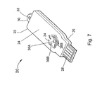
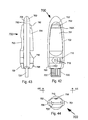
- USB pendant device 20 generally comprises casing or housing 22 which has top portion 24 and bottom portion 26.
- USB pendant device 20 further comprises USB connector 28 that is configured to be plugged or inserted into a USB port (not shown) of a computer or a peripheral device.
- casing 22 includes protruding portion 30 that defines opening 32.
- a key ring chain, string, strap or wire can be inserted into opening 32 so that the USB pendant device 20 can be hung around a user's neck.
- Top portion 24 of casing 22 includes section 34 which has fragrance vents 36A and 36B from which a fragrance is emitted.
- Fragrance vent 36A is a central fragrance vent.
- Air vent 38 is located in bottom portion 26 and allows air to enter the interior of casing 22 (see FIG. 8 ).
- USB pendant device 20 includes post 39 and support base 40 that are attached to bottom portion 26 of casing 22.
- Support base 40 has an interior portion within which is positioned heating element 42.
- Heating element 42 generates heat when electrical power is applied thereto.
- Heating element 42 can be almost any type of electrical device that generates heat when electrical power is applied thereto.
- heating element 42 is a resistor having electrical conductors 44 that are electrically connected to USB connector 28.
- USB pendant device 20 further comprises fragrance member 50 that is supported by support base 40 such that fragrance member 50 is positioned over heating element 42.
- Fragrance member 50 is shown in phantom in FIG. 1 ).
- Fragrance member 50 is entirely located within the interior of casing 22. Thus, no portion of fragrance member 50 is external to casing 22.
- Fragrance member 50 emits a desired fragrance, scent or aroma when heat is applied thereto.
- fragrance member 50 can be configured as an absorbent member that is soaked or saturated with a liquid substance that emits a desired fragrance, scent or aroma when heat is applied thereto. Examples of liquid substances include oils and perfumes.
- fragrance member 50 comprises a device that is coated with a substance that emits a desired fragrance, scent or aroma when heat is applied thereto.
- fragrance member 50 comprises a capsule or small container that contains a liquid that emits a desired fragrance when heat is applied thereto.
- Fragrance member 50 can be configured to emit any one of variety of fragrances, aromas or scents, e.g. perfumes, fruit, flowers, etc.
- fragrance member 50 has a generally rectangular shape.
- fragrance member 50 has a generally square shape, as shown in FIGS. 1 and 5 .
- fragrance member 50 has a generally circular, planar shape.
- USB pendant device 20 further comprises protective tab 60.
- Protective tab 60 comprises a first portion 60A that is initially positioned within the interior of USB pendant device 20 and a second portion 60B that is external to casing 22. First portion 60A is positioned between fragrance member 50 and vents 36A and 36B.
- Protective tab 60 has opening 60C that is adjacent to slit 60D. Opening 60C is sized to receive post 39 (see FIGS. 5 and 8 ).
- Protective tab 60 ensures that fragrance member 50 remains fresh and does not experience diminished fragrance emitting efficacy. Thus, protective tab 60 extends the shelf life of fragrance member 50 prior to use.
- the user pulls out protective tab 60 in the direction indicated by arrow 70 in FIG.
- Post 39 slides through slit 60D in protective tab 60.
- the user can then insert USB connector 28 in a USB port (not shown) of a computer or peripheral device.
- USB connector 28 Once electrical power is applied to USB connector 28, electrical power is applied to heating element 42.
- heating element 42 In response to the electrical power, heating element 42 generates heat which causes fragrance member 50 to emit a fragrance.
- the fragrance is emitted through vents 36A and 36B.
- Air vent 38 allows air to flow into casing 22 to prevent heating element 42 from overheating.
- heating element 42 is fixed to the support base 40 so that it is not movable.
- fragrance member 50 of USB pendant device 20 does not rotate. Furthermore, fragrance member 50 is located entirely within the interior of casing 22.
- USB pendant device 20 has an overall shape that is substantially the same as the shape of a USB flash memory drive.
- USB pendant device 100 generally comprises casing 102.
- Casing 102 comprises top portion 104 and bottom portion 106.
- USB pendant 100 further comprises USB connector 108 which is configured to be plugged into a USB port (not shown) of a computer (not shown) or peripheral device (not shown).
- Top portion 104 has cover portion 110 which has a concave shape.
- Cover portion 110 has a plurality of fragrance vents 112 and 113 formed therein, wherein fragrance vent 112 is a central vent and is centrally located in cover portion 110.
- bottom portion 106 of casing 102 has air vent 114 to allow air to flow into interior 116 of casing 102.
- Top portion 104 of casing 102 has a support section 120 beneath cover portion 110 so as to define space 122.
- Support section 120 has a plurality of vents 124 therein.
- USB pendant device 100 further includes fragrance member 130 that is entirely positioned in space 122.
- Cover portion 110 is attached to support section 120. Specifically, support section 120 has openings 125 to receive tabs 134 of cover portion 110.
- USB pendant device 100 further includes support member 140 that is located within interior 116 and attached to bottom section 106.
- USB pendant device 100 also includes heating element 150 which is supported by support member 140.
- Electrical conductor 160 is connected to USB connector 108 and heating element 150. Electrical conductor 160 provides electrical power to heating element 150 when USB connector 108 is plugged into a USB port (not shown).
- electrical power is applied to heating element 150 via electrical conductor 160.
- heating element 150 generates heat which passes through openings 124 in support section 120. This heat causes fragrance member 130 to emit a fragrance. The fragrance is emitted through vents 112 and 113.
- a key feature of USB pendant device 100 is that a user may replenish fragrance member 130 with a fragrance producing substance by depositing such substance on the concave-shaped cover portion 110.
- the concave surface of cover portion 110 enables the fragrance producing substance to flow into central fragrance vent 112 in cover portion 110 and fall or drop onto fragrance member 130.
- the fragrance producing substance is an oil or perfume
- the user can insert drops of oil into fragrance vent 112.
- the concave surface of cover portion 110 will cause any excess oil to flow into central fragrance vent 112.
- USB pendant device 100 has an overall shape that is substantially the same as the shape of a USB flash memory drive.
- USB flash memory drives also known as USB stick drives
- USB flash memory drives are well known in the computer field and are used to store computer data files.
- a USB flash memory drive contains a data storage element, such as a memory chip, and other electronic components. When the USB flash memory drive is in use, the data storage element and/or other electronic components generate heat.
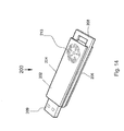
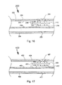
- FIGS. 14 and 15 a USB flash memory drive 200 which provides a fragrance or aroma when USB flash memory drive 200 is in operation.
- USB flash memory drive 200 has a housing 202 which comprises top section 204 and bottom section 206.
- USB flash memory drive 200 further comprises circuit support member 208 that is between top section 204 and bottom section 206.
- USB connector section 209 is electrically connected to circuit support member 208.
- USB connector section 209 is configured to be connected or inserted into a USB port of a computer or other data transfer device.
- Housing 202 further includes cover section 210 (shown in phantom) that covers USB connector section 209. Cover section 210 is removable.
- Housing 202 includes vent 213 located in the top section 204. The purpose of vent 213 is discussed in the ensuing description.
- USB flash memory drive 200 further includes electronic component 214 that is electrically connected to circuit support board 208 and is part of the data storage circuitry and generates heat as a result of the operation of the data storage circuitry.
- Electronic component 214 can be any electronic component associated with the data storage circuitry, e.g. integrated circuit, resistor, etc.
- electronic component 214 is added specifically to circuit support board 208 for the purpose of generating heat and is not pertinent to the data storage function of USB flash memory drive 200.
- USB flash memory drive 200 further comprises device 216 that emits a fragrance, scent or aroma when heat is applied thereto.
- Device 216 can have any one of several configurations.
- device 216 can be configured to contain or hold a liquid or solid substance that emits a desired fragrance, scent or aroma when heat is applied thereto.
- a liquid substance include oils and perfumes.
- device 216 is coated with a substance that emits a desired fragrance, scent or aroma when heat is applied thereto.
- device 216 comprises an absorbent member that is soaked or saturated with a liquid substance that emits a desired fragrance, scent or aroma when heat is applied thereto.
- Other configurations for device 216 are possible.
- Device 216 can be configured to emit any one of variety of fragrances, aromas or scents, e.g. perfumes, fruit, flowers, etc.
- Device 216 is attached to support member 218.
- support member 218 is attached to interior wall 220 of housing 202 and is adjacent to vent 213.
- Support member 218 is shaped and configured so as to allow device 216 to be positioned over and very close to electronic component 214.
- electrical power is applied to electronic component 214 which, in response, generates heat 222.
- Heat 222 causes device 216 to emit a fragrance, scent or aroma 224 that passes through vent 213.
- housing 202 further includes vent 225. Vent 225 is located in bottom section 206 of housing 202. Vent 225 allows airflow into the interior of housing 202 to prevent overheating of the electronic components therein.
- Housing 202 can be configured to have any one of a variety of suitable shapes and designs.
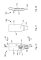
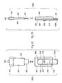
- FIG. 14 Another example is shown in FIG. 18 .
- USB flash memory drive 300 comprises housing 302 which has a rounded end portion 304 and a tapered geometry.
- Housing 302 includes cover section 306 that covers the USB connector section (not shown but generally the same as USB connector section 209 shown in FIG. 15 ).
- Housing 302 includes a stylish vent section 308 from which the fragrance, scent or aroma exits the interior of the housing.
- FIG. 17 shows a partial, cross-sectional view of USB flash memory drive 400 in accordance with an alternate embodiment of the invention.
- USB flash drive 400 comprises housing 402 which has top portion 404 and bottom portion 406. Housing 402 includes vent 407 in top portion 404. Vent 407 is similar to vent 213 (see FIGS. 14 and 15 ).
- USB flash memory drive 400 further includes circuit support member 408 and device 409 which emits a fragrance, scent or aroma when heat is applied thereto. In accordance with this embodiment, device 409 is connected to support member 410 which is connected to circuit support member 408.
- USB flash memory drive 400 further comprises an electronic component 412 that is electrically connected to circuit support member 408 and which generates heat 414 in a manner similar to electronic component 214 (see FIG. 16 ).
- housing 402 further includes vent 417. Vent 417 is located in bottom portion 406 of housing 402. Vent 417 allows airflow into the interior of housing 402 to prevent overheating of the electronic components therein.
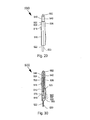
- fragrance emitting apparatus 500 in accordance with another embodiment of the present invention.
- fragrance emitting apparatus 500 has an appearance similar to that of a flash memory drive.
- Apparatus 500 generally comprises casing 502 that has top section 504 and bottom section 506.
- Bottom section 506 has a vent 507 (see FIG. 24 ) that allows air to flow into interior 525 of casing 502.
- Top section 502 has a recessed area 509.
- Apparatus 500 further includes air vent cover 510.
- Air vent cover 510 includes portion 510A. Air vent cover 510 is slidably attached to casing 502. Specifically, air vent cover 510 can bi-directionally slide within recessed area 509.
- Top section 502 includes tracks 512 and 514 that are in either side of recessed area 509. Air vent cover 510 is slidably engaged to tracks 512 and 514. Air vent cover 510 has a vent 516. The purpose of vent 516 is discussed in the ensuing description. Vent cover 510 has a plurality of projections 518 that provide a frictional surface for a user's finger. Thus, projections 518 facilitate sliding air vent cover 510 bi-directionally to either a closed or open position.
- Apparatus 500 further includes USB connector 520 that is configured to be plugged into a USB port (not shown) of a computer or of a computer peripheral device, or any other electronic device that employs a USB port (see FIGS. 21 and 23 ).
- USB connector 520 has a printed circuit section 522 (see FIGS. 27 and 28 ). The portion 510A of the vent cover 510 covers USB connector 520 when air vent cover 510 is in the closed position.
- casing 502 has an interior 525 and an opening 530 in communication with interior 525.
- Apparatus 500 further comprises cartridge case 540 that has section 542 and section 544.
- Fragrance member 550 is attached to section 544.
- Fragrance member 550 emits a desired fragrance, scent or aroma when heat is applied thereto.
- fragrance member 550 can be configured as an absorbent member that is soaked or saturated with a liquid substance that emits a desired fragrance, scent or aroma when heat is applied thereto. Examples of liquid substances include oils and perfumes.
- fragrance member 550 comprises a device that is coated with a substance that emits a desired fragrance, scent or aroma when heat is applied thereto.
- Fragrance member 550 can be configured to emit any one of variety of fragrances, aromas or scents, e.g. perfumes, fruit, flowers, etc.
- fragrance member 550 has a generally square shape.
- fragrance member 550 can be configured to have other shapes as well.
- Section 542 of casing 540 includes eyelet 552 that is sized to receive a strap or chain which the user can place around his or her neck. Opening 530 is sized to receive section 544 of cartridge case 540.
- Interior 525 of casing 502 is sized to receive fragrance member 550 and all of section 544 of cartridge case 540.
- cartridge case 540 can be removably secured to casing 502 by inserting section 544 into opening 530 and sliding section 544, and fragrance member 550 into interior 525.
- Casing 502 is structured so that there is a slight frictional relationship between the inner structure of casing 502 and section 544 of cartridge case 540 so that cartridge case 540 does not slip out from interior 525.
- a user can remove cartridge case 540 and replace it with another cartridge case 540 having a fresh fragrance member 550.
- fragrance emitting apparatus 500 further comprises heating element 560 located in interior 525.
- Heating element 560 can be realized by any one of a variety of electrical components that generate heat when electrical power is applied thereto.
- heating element 560 is a resistor having electrically conductive leads or wires 562 that are electrically connected to printed circuit section 522 of USB connector 520. Electrically conductive leads 562 have a degree of stiffness to keep resistor 560 in proximity to fragrance member 550.
- USB connector 520 is plugged into a USB port (not shown) of a computer or computer peripheral device, electrical power is provided to printed circuit section 522. As a result, electrical power is applied to resistor 560 that causes resistor 560 to generate heat.
- Top section 504 of casing 502 has vent 570 that is in proximity to and aligned with fragrance member 550.
- air vent cover 510 When air vent cover 510 is slid to the closed position, as shown FIGS. 19, 20 , 25 and 26 , the portion 510A of air vent cover 510 completely covers printed circuit section 522 and the other portion of air vent cover 510 covers vent 570.
- vent 516 in air vent cover 510 is positioned over and is aligned with air vent 570.
- fragrance member 550 when fragrance member 550 is plugged into a USB port of a computer or a peripheral device and air vent cover 510 is slid into the open position, electrical power is applied to resistor 560 thereby causing resistor 560 to generate heat. This heat causes fragrance member 550 to emit a fragrance which passes through vents 570 and 516 and into the surrounding environment.
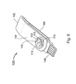
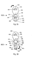
- apparatus 600 has the shape of a piece of jewelry. However, it is to be understood that apparatus 600 can be configured to have other shapes as well.
- Apparatus 600 comprises casing 601 having top section 602 and bottom section 604.
- Top section 602 is rotatably attached to bottom section 604 at rotation joint 606 (see FIGS. 31 and 35 ).
- Top section 602 has air vent 608 therein that comprises a plurality of differently shaped openings 609.
- Bottom section 604 has an air vent 610 (see FIG. 33 ).
- Bottom section 604 also includes top portion 612 (see FIGS. 35, 36 and 38 ).
- Top portion 612 has recess 613, the purpose of which will be discussed in the ensuing description.
- Apparatus 600 further includes a strap or chain loop 614 that is attached to bottom section 604 and which is configured to receive chain or strap 616. A user can place chain or strap 616 around his or her neck.
- top section 602 can rotate 360° with respect to bottom section 604 as shown in FIGS. 35, 36 and 37A .
- apparatus 600 further comprises USB connector 620 that is pivotally attached to bottom section 604 at joint or pin 622.
- USB connector 620 is configured to be plugged into a USB port (not shown) of a computer or a peripheral device.
- USB connector 620 has printed circuit section 624.
- USB connector 620 pivots within recess 613 and allows the user to pivot USB connector 620 upward as shown in FIG. 35 or downward as shown in FIG. 36 . Once USB connector 620 is pivoted upward as shown in FIG. 35 , the user can then pivot top section 602 downward as shown in FIGS. 31 and 32 so as to cover USB connector 620.
- Joint or pin 622 is electrically conductive and is electrically connected to printed circuit section 624 of USB connector 620.
- Apparatus 600 further comprises heating element 630 which generates heat when electrical power is applied thereto.
- Heating element 630 can be any device or electrical component that generates heat when electrical power is applied thereto.
- heating element 630 is a resistor.
- Heating element 630 is electrically connected to joint or pin 622 via electrically conductive lead or leads 632.
- USB connector 620 When USB connector 620 is plugged into a USB port, electrical power is applied to printed circuit section 624, pin or joint 622, lead 632, and thus heating element 630. As a result, heating element 630 generates heat. This feature is further discussed in the ensuing description.
- bottom section 604 has an opening 640 that is sized to receive cartridge 642.
- Bottom section 604 also has opening 644 which functions as a vent.
- Top portion 612 includes portion 645 that is located between opening 640 and vent 644.
- Cartridge 642 comprises frame member 646 and fragrance member 648 that is attached to frame member 646.
- Fragrance member 648 provides a fragrance or aroma when heat is applied thereto.
- Fragrance member 648 can be fabricated from the same material used to fabricate fragrance member 550 (see FIG. 21 ) which is described in the foregoing description. Opening 640 allows cartridge 642 to be removably positioned within bottom section 604.
- heating element 630 is located at a predetermined position within bottom section 604 so that when cartridge 642 is positioned within bottom section 604, fragrance member 648 is positioned adjacent to heating element 630 (see FIGS. 34 and 40 ).
- the user In order to use apparatus 600, the user first pivots top section 602 to the position shown in FIG. 35 . The user then pivots USB connector 620 in the direction indicated by arrow 650 shown in FIG. 36 . Next, the user then pivots top section 602 so that it is repositioned in its original position (see FIGS. 38 and 39 ). The user is ready to plug USB connector 620 into a USB port of a computer or peripheral device.
- electrical power is applied to printed circuit section 624.
- electrical power is applied to heating element 630.
- heating element 630 In response to the electrical power, heating element 630 generates heat which causes fragrance member 648 to emit a fragrance or aroma which passes through opening 644.
- the opening 644 functions as a vent.
- USB connector 620 Once the user removes USB connector 620 from the USB port of the computer or peripheral device, the electrical power previously applied to resistor 630 is discontinued. The user then pivots top section 602 to the position shown in FIGS. 35 and 36 . Next, the user then pivots USB connector 620 in a direction that is opposite arrow 650 (see FIG. 36 ) so that USB connector 620 is positioned as shown in FIG. 35 , The user then pivots top section 602 so that it is positioned as shown in FIGS. 31 and 32 so as to cover USB connector 620.
- fragrance member 648 no longer provides the desired level of fragrance or aroma, the user can replace cartridge 642 with a new cartridge having a fresh fragrance member.
- Fragrance emitting apparatus 700 comprises casing 701 that has top section 702 and bottom section 706.
- Apparatus 700 further comprises a USB connector 720 which has printed circuit section 722.
- USB connector 720 functions in the same manner as USB connector 520 described in the foregoing description (see FIG. 27 ).
- Apparatus 700 includes a through-opening 752 through which a strap or chain can be inserted so as to allow the user to hang apparatus 700 around his or her neck or to hang the apparatus 700 on a hook, etc.
- Apparatus 700 includes LED (light-emitting diode) 795 that is electrically connected to printed circuit section 722.
- Apparatus 700 further comprises door 791 that is pivotally attached to top section 702 of casing 701. Door 791 includes spring-lock 792 which secures door 791 in a closed position. The purpose of door 791 will be explained in the ensuing description.
- Apparatus 700 further comprises a vent system that comprises a rotatable member 710 and vent 718.
- Rotatable member 710 is positioned in casing 701 and is configured to rotate between two positions. A portion of rotatable member 710 is exposed at the top side of casing 701 (see FIG. 42 ) and a portion of rotatable member 710 is exposed at the bottom side of casing 701 (see FIG. 45 ).
- Rotatable member 710 has vent 716 and therefore, vent 716 rotates with member 710.
- Vent 718 is located in top section 702 of casing 701. Vent 718 is in communication with the interior 770 of casing 701. Rotatable member 710 is rotated between a first position wherein vent 716 is aligned with vent 718, and a second position wherein vent 716 is not aligned with vent 718 thereby closing off vent 718.
- apparatus 700 has an interior 770 that is sized to receive fragrance bottle 740.
- Fragrance bottle 740 includes a fragrance member 750 that extends from fragrance bottle 740.
- Fragrance bottle 740 contains a liquid such as perfume or oil that has a desired fragrance.
- Fragrance member 750 is configured as an absorbent material that absorbs the liquid in fragrance bottle 740.
- apparatus 700 further comprises heating element 760.
- Heating element 760 can be configured as a device or electrical component that generates heat when electrical power is applied thereto. In one embodiment, heating element 760 is a resistor. Heating element 760 is electrically connected to printed circuit section 722 of USB connector 720 by electrically conductive lead or leads 762.
- the electrically conductive lead 762 has a degree of stiffness that allows heating element 760 to be positioned adjacent to fragrance member 750.
- fragrance member 750 contacts heating element 760.
- the user may close door 791.
- Door 791 includes stopper member 793 that abuts fragrance bottle 740 when door 791 is closed (see FIG. 48 ) and thus, prevents movement of fragrance bottle 740.
- spring lock 792 further comprises a resilient generally “V” shaped member 792A and a projection 792B is attached to the generally “V” shaped member 792A.
- the user pushes tip 792C in the direction indicated by arrow 799, and then lowers door 791 so that projection 792B is positioned underneath extending lip 705 of top section 702.
- the user then releases tip 792C so that "V" shaped member 792A expands to its normal position thereby maintaining projection 792B beneath extending lip 705 and causing projection 792B to abut extending lip 705.
- apparatus 700 further includes an opening 790 which functions as a window. Opening 790 allows a user to view the interior 770 of casing 701 without opening door 791.
- a user rotates rotatable member 710 so that vent 716 is aligned with vent 718.
- the user plugs USB connector 720 into a USB port (not shown) of an operating computer or peripheral device so that electrical power is applied to printed circuit section 722 and hence, heating element 760.
- heating element 760 generates heat that causes fragrance member 750 member to emit the fragrance or scent associated with the liquid in fragrance bottle 740.
- the fragrance or scent exits casing 701 through vents 716 and 718.
- the user can open door 791 and replace fragrance bottle 740 with a new fragrance bottle.
- Casing 701 and door 791 may be manufactured from any one of a variety of suitable materials, e.g. plastic.
- All of the embodiments of the apparatus of the present invention described in the foregoing description may be fabricated from any suitable material, e.g. plastic, resin, composite, cardboard, wood, etc.
Landscapes
- Health & Medical Sciences (AREA)
- Epidemiology (AREA)
- Life Sciences & Earth Sciences (AREA)
- Animal Behavior & Ethology (AREA)
- General Health & Medical Sciences (AREA)
- Public Health (AREA)
- Veterinary Medicine (AREA)
- Disinfection, Sterilisation Or Deodorisation Of Air (AREA)
- Mechanical Pencils And Projecting And Retracting Systems Therefor, And Multi-System Writing Instruments (AREA)
Claims (3)
- Ein USB Flash Speicher Laufwerk, welches ein Gehäuse (202) mit einem oberen Abschnitt (204), einem unteren Abschnitt (206), einem Innenraum und einen sich aus dem Gehäuse (202) erstreckenden USB-Anschlussabschnitt (209) umfasst, gekennzeichnet dadurch, dass das USB-Flashspeicherlaufwerk weiterhin- ein innerhalb Gehäuses (202) angeordnetes und mit diesem verbundenes Tragglied für die elektronische Komponente (208), wobei der USB-Anschlussabschnitt (209) mit dem Tragglied für die elektronische Komponente (208) elektrisch verbunden ist,- eine mit dem Tragglied für die elektronische Komponente (208) elektrisch verbundene elektronische Komponente (214), wobei die elektronische Komponente (214) bei in Betrieb befindlichem USB-Flashspeicherlaufwerk (200) Wärme erzeugt ist,- eine in dem Gehäuse (202) befindliche und mit dem Inneren des Gehäuses (202) in Verbindung stehende Lüftungsöffnung (213), sowie- ein innerhalb Gehäuses (202) angeordnetes und mit diesem verbundenes stationäres Gerät (216), welches eine Substanz enthält, die durch Anlegen von Wärme an das Gerät (216) einen Duftstoff, einen Geruch oder ein Aroma aussendet, wobei das Gerät (216) sich in unmittelbarer Nähe der elektronischen Komponente (214) befindet und durch die von der elektronischen Komponente (214) erzeugte Wärme veranlasst wird, den Duftstoff, den Geruch oder das Aroma auszusenden, und wobei der Duftstoff, der Geruch oder das Aroma das Innere des Gehäuses (202) durch die Lüftungsöffnung (213) verlässt,umfasst.
- Das USB-Flashspeicherlaufwerk gemäß Anspruch 1, worin die Lüftungsöffnung (213) sich in dem oberen Abschnitt (204) des Gehäuses (202) befindet.
- Das USB-Flashspeicherlaufwerk gemäß Anspruch 2, enthaltend weiterhin eine zweite Lüftungsöffnung (225) in dem unteren Abschnitt (206) des Gehäuses (202).
Priority Applications (1)
| Application Number | Priority Date | Filing Date | Title |
|---|---|---|---|
| EP11185456A EP2450060A1 (de) | 2006-05-15 | 2007-05-10 | Duftabgebendes Gerät zur Verwendung mit einem USB-Port |
Applications Claiming Priority (3)
| Application Number | Priority Date | Filing Date | Title |
|---|---|---|---|
| US74722106P | 2006-05-15 | 2006-05-15 | |
| US80619106P | 2006-06-29 | 2006-06-29 | |
| PCT/CN2007/001526 WO2007137483A1 (en) | 2006-05-15 | 2007-05-10 | Fragrance emitting apparatus for use with usb port |
Publications (3)
| Publication Number | Publication Date |
|---|---|
| EP2023966A1 EP2023966A1 (de) | 2009-02-18 |
| EP2023966A4 EP2023966A4 (de) | 2010-06-23 |
| EP2023966B1 true EP2023966B1 (de) | 2011-10-19 |
Family
ID=38778101
Family Applications (2)
| Application Number | Title | Priority Date | Filing Date |
|---|---|---|---|
| EP07721099A Not-in-force EP2023966B1 (de) | 2006-05-15 | 2007-05-10 | Duft abgebendes gerät zur verwendung mit einem usb-port |
| EP11185456A Withdrawn EP2450060A1 (de) | 2006-05-15 | 2007-05-10 | Duftabgebendes Gerät zur Verwendung mit einem USB-Port |
Family Applications After (1)
| Application Number | Title | Priority Date | Filing Date |
|---|---|---|---|
| EP11185456A Withdrawn EP2450060A1 (de) | 2006-05-15 | 2007-05-10 | Duftabgebendes Gerät zur Verwendung mit einem USB-Port |
Country Status (6)
| Country | Link |
|---|---|
| US (1) | US8032014B2 (de) |
| EP (2) | EP2023966B1 (de) |
| JP (1) | JP2009537287A (de) |
| CN (1) | CN101389359B (de) |
| AT (1) | ATE529139T1 (de) |
| WO (1) | WO2007137483A1 (de) |
Families Citing this family (43)
| Publication number | Priority date | Publication date | Assignee | Title |
|---|---|---|---|---|
| KR101413009B1 (ko) * | 2007-10-05 | 2014-08-07 | 삼성전자주식회사 | 방향 부재를 갖는 이동통신 단말기 |
| JP2009156823A (ja) * | 2007-12-27 | 2009-07-16 | Shimadzu Corp | においメモリチップ |
| US8068725B2 (en) * | 2008-02-05 | 2011-11-29 | David Cheung | Fragrance emitting apparatus for use with USB port |
| TWI350962B (en) * | 2008-11-05 | 2011-10-21 | Phison Electronics Corp | Memory disk and housing thereof |
| CN101753661A (zh) * | 2008-12-04 | 2010-06-23 | 深圳富泰宏精密工业有限公司 | 便携式芳香通讯装置 |
| US8090244B2 (en) | 2009-01-09 | 2012-01-03 | S.C. Johnson & Son, Inc. | Volatile material dispenser |
| US20110132995A1 (en) * | 2009-12-09 | 2011-06-09 | Usb Flower, Ltd | Fragrance dispenser with replaceable cartridges |
| US8125774B2 (en) | 2010-06-14 | 2012-02-28 | Share Memories, Llc | Portable keepsake storage device with a pivoting sleeve and USB flash drive |
| US20120018529A1 (en) * | 2010-07-20 | 2012-01-26 | Gammon Frederick A | Air Freshener Device |
| US20120034819A1 (en) * | 2010-08-05 | 2012-02-09 | Ever Win International Corporation | Micro Universal Serial Bus Adapter |
| EP2433656A1 (de) | 2010-09-23 | 2012-03-28 | Unilever PLC | Duftabgabevorrichtung |
| US8792781B1 (en) * | 2010-10-06 | 2014-07-29 | Rochester CCC Incorporated | Personal fluid warming device and associated methods |
| US8376760B1 (en) * | 2011-01-27 | 2013-02-19 | Physical Optics Corporation | Avionics data storage device and transfer system with electro-opto-mechanical identification |
| USD688364S1 (en) | 2011-07-19 | 2013-08-20 | Frederick A. Gammon | Air freshener device |
| USD665064S1 (en) * | 2011-08-01 | 2012-08-07 | D Amico Daniel | Air freshener housing |
| USD666284S1 (en) | 2011-10-27 | 2012-08-28 | Smith Mountain Industries, Inc. | Air freshener case |
| JP2013111199A (ja) * | 2011-11-28 | 2013-06-10 | Imari:Kk | 芳香器 |
| US8784747B2 (en) | 2011-12-22 | 2014-07-22 | Marcy Carmichael | Fragrance dispenser for use with portable electronic device |
| CN102743005B (zh) * | 2012-07-24 | 2015-03-25 | 张家港市俊锋玻璃制品有限公司 | 一种香水瓶 |
| CN103685653A (zh) * | 2012-09-14 | 2014-03-26 | 凹凸电子(武汉)有限公司 | 具有香味发生功能的电子设备 |
| JP5781107B2 (ja) * | 2013-02-22 | 2015-09-16 | 株式会社東芝 | Usb装置 |
| CN105492031A (zh) | 2013-03-15 | 2016-04-13 | 韦伯通信股份有限公司 | 提供嗅觉感知的系统、方法和制品 |
| JP2016518165A (ja) | 2013-03-15 | 2016-06-23 | ベイパー コミュニケーションズ, インコーポレーテッドVapor Communications, Inc. | 嗅覚感覚を提供するためのシステム、方法及び物品 |
| CN105358181B (zh) | 2013-04-22 | 2019-06-11 | 加利福尼亚大学董事会 | 可切换气体和液体释放和输送设备、系统和方法 |
| USD698913S1 (en) * | 2013-08-13 | 2014-02-04 | David Cheung | Fragrance emitting device for use with a smart phone |
| USD699829S1 (en) * | 2013-08-15 | 2014-02-18 | David Cheung | Fragrance emitting device for use with a smart phone |
| US20150102079A1 (en) * | 2013-10-16 | 2015-04-16 | Kuo-Chung Yang | Mobile electronic device protective cover with fragrance emitting means |
| CN103574780B (zh) * | 2013-11-05 | 2015-11-25 | 谢虹 | 一种微型负离子空气净化器 |
| US9645617B2 (en) | 2013-11-06 | 2017-05-09 | Northrop Grumman Systems Corporation | Compact memory device |
| US9256253B2 (en) * | 2013-12-28 | 2016-02-09 | Intel Corporation | Clasp assembly and data interconnection for wearable computing devices |
| CN203775583U (zh) * | 2014-01-26 | 2014-08-13 | 中兴通讯股份有限公司 | 一种移动终端散热机构及具有该机构的终端 |
| US9730347B2 (en) * | 2015-02-20 | 2017-08-08 | Christopher W. E. Cote | Scented universal serial bus drives and methods to make the same |
| CN107847958B (zh) | 2015-04-10 | 2024-01-16 | 加利福尼亚大学董事会 | 可切换的数字气味产生和释放以及蒸气和液体递送方法及系统 |
| CN104869769A (zh) * | 2015-05-13 | 2015-08-26 | 马玉荣 | 一种防振u盘 |
| US11207438B2 (en) | 2015-05-27 | 2021-12-28 | S. C. Johnson & Son, Inc. | Low wattage powered wax warmers |
| US10207018B2 (en) | 2015-05-27 | 2019-02-19 | S.C. Johnson & Son, Inc. | Low wattage USB powered wax warmers |
| US10709973B2 (en) | 2015-06-12 | 2020-07-14 | Sony Interactive Entertainment Inc. | Fragrance presentation device |
| CN105470758B (zh) * | 2015-11-20 | 2017-12-29 | 苏州佳世达电通有限公司 | Usb连接线 |
| US20190105460A1 (en) | 2017-09-11 | 2019-04-11 | Sensory Cloud, Llc | Compositions, systems, methods, and articles for retro-nasal delivery |
| KR102545567B1 (ko) * | 2018-02-28 | 2023-06-19 | 안동대학교 산학협력단 | 필름형 향기 발산 장치 및 그 제조방법 |
| CN108402642A (zh) * | 2018-05-17 | 2018-08-17 | 刘雄波 | 一种内置景观石的主动散香型车载香水瓶 |
| US12337064B2 (en) | 2018-09-05 | 2025-06-24 | Sensory Cloud, Inc. | Formulations and compositions for ortho- and/or retro-nasal delivery and associated systems, methods and articles |
| CN109999210A (zh) * | 2019-04-20 | 2019-07-12 | 阮榛 | 设备内置的散热燃香系统 |
Family Cites Families (19)
| Publication number | Priority date | Publication date | Assignee | Title |
|---|---|---|---|---|
| US4880690A (en) * | 1984-11-13 | 1989-11-14 | Thermedics, Inc. | Perfume patch |
| US6162457A (en) * | 1998-09-08 | 2000-12-19 | Martz; Christine | Personal perfume application method and system |
| WO2001030404A1 (en) * | 1999-10-29 | 2001-05-03 | E. One Co., Ltd. | Scent diffusion apparatus and method thereof |
| US20030206834A1 (en) | 2000-11-16 | 2003-11-06 | Chiao Dahshiarn | Replaceable scent and multimedia storage medium for use with a playback apparatus having electrostatic scents release |
| TW532653U (en) * | 2001-11-06 | 2003-05-11 | Yea-Yen Huang | USB powered perfume connector |
| CN2526001Y (zh) * | 2001-11-14 | 2002-12-18 | 黄月云 | Usb插电香连接头 |
| AU2003223515A1 (en) | 2002-04-08 | 2003-10-27 | Joseph Manne | Portable scent delivery device |
| CN2628913Y (zh) * | 2003-01-21 | 2004-07-28 | 梁平 | 电脑usb接口一体化空气清新机 |
| US7200363B2 (en) * | 2003-01-22 | 2007-04-03 | Motorola, Inc. | Communication device having a scent release feature and method thereof |
| TW583003B (en) | 2003-05-23 | 2004-04-11 | Benq Corp | Mobile phone and odorant module thereof |
| CN2628931Y (zh) * | 2003-06-03 | 2004-07-28 | 海尔集团公司 | 一种空调器的易拆卸清洁左右方向叶片 |
| US20050013728A1 (en) * | 2003-07-17 | 2005-01-20 | First International Computer Inc. | Fragrance generation device |
| CN2666048Y (zh) * | 2003-09-16 | 2004-12-22 | 联想(北京)有限公司 | 手持设备 |
| CN2672977Y (zh) * | 2003-10-24 | 2005-01-19 | 联想(北京)有限公司 | 手持设备 |
| CN2735677Y (zh) * | 2004-06-02 | 2005-10-19 | 周仲平 | 一种可挥发香味的手机 |
| CN2715759Y (zh) * | 2004-06-09 | 2005-08-10 | 上海迪比特实业有限公司 | 一种便携式电子产品 |
| CN100335988C (zh) * | 2004-08-12 | 2007-09-05 | 英业达股份有限公司 | Usb芳香器 |
| CN2738806Y (zh) * | 2004-10-21 | 2005-11-09 | 陈菱莹 | 芳香器结构 |
| US20060258215A1 (en) * | 2005-05-12 | 2006-11-16 | Chang-Chin Lai | USB aromatic dispenser |
-
2007
- 2007-05-10 EP EP07721099A patent/EP2023966B1/de not_active Not-in-force
- 2007-05-10 EP EP11185456A patent/EP2450060A1/de not_active Withdrawn
- 2007-05-10 WO PCT/CN2007/001526 patent/WO2007137483A1/en not_active Ceased
- 2007-05-10 US US12/295,647 patent/US8032014B2/en not_active Expired - Fee Related
- 2007-05-10 AT AT07721099T patent/ATE529139T1/de not_active IP Right Cessation
- 2007-05-10 CN CN2007800064143A patent/CN101389359B/zh not_active Expired - Fee Related
- 2007-05-10 JP JP2009513536A patent/JP2009537287A/ja active Pending
Also Published As
| Publication number | Publication date |
|---|---|
| HK1130700A1 (en) | 2010-01-08 |
| EP2023966A4 (de) | 2010-06-23 |
| ATE529139T1 (de) | 2011-11-15 |
| EP2450060A1 (de) | 2012-05-09 |
| EP2023966A1 (de) | 2009-02-18 |
| JP2009537287A (ja) | 2009-10-29 |
| WO2007137483A1 (en) | 2007-12-06 |
| CN101389359B (zh) | 2012-05-30 |
| US8032014B2 (en) | 2011-10-04 |
| US20090261181A1 (en) | 2009-10-22 |
| CN101389359A (zh) | 2009-03-18 |
Similar Documents
| Publication | Publication Date | Title |
|---|---|---|
| EP2023966B1 (de) | Duft abgebendes gerät zur verwendung mit einem usb-port | |
| US8625977B2 (en) | Fragrance emitting apparatus for use with USB port | |
| ES2258269T3 (es) | Aparato dispensador de vapor calentado electricamente. | |
| JP4435576B2 (ja) | 携帯型匂い送出装置 | |
| JP5891245B2 (ja) | 加熱された製品を試供するためのアセンブリ | |
| US20080194144A1 (en) | Usb device insulation sheath and method of insulating a usb device | |
| AU2016267067B2 (en) | Low wattage USB powered wax warmers | |
| BRPI0709664A2 (pt) | dispensador de material volátil | |
| CN110742323B (zh) | 雾化吸入装置 | |
| WO2008156805A1 (en) | Diffusion device | |
| US20110132995A1 (en) | Fragrance dispenser with replaceable cartridges | |
| KR20220063577A (ko) | 에어로졸 생성 장치용 카트리지 및 이를 포함하는 카트리지 조립체 | |
| ES2299693T3 (es) | Dispositivo electrico para perfumar el interior de un vehiculo. | |
| HK1130700B (en) | Fragrance emitting apparatus for use with usb port | |
| EP1622664B1 (de) | Verbesserung bezüglich verdampfer | |
| WO2007058031A1 (ja) | 小型記録媒体用コネクタ | |
| JP2014513403A (ja) | 揮発性物質ディスペンサ用回転式電気プラグ組立品 | |
| KR20200022922A (ko) | 휴대 및 도킹 사용 가능한 디퓨저 어셈블리 | |
| KR101960229B1 (ko) | 전기식 캔들팟 | |
| PH12014501886B1 (en) | Systems and devices for dispensing volatile materials | |
| JP5126697B2 (ja) | 香炉器具 | |
| KR200313779Y1 (ko) | 시거잭을 이용한 향 발현장치 | |
| CN120693078A (zh) | 汽化器及包括该汽化器的气溶胶生成装置 | |
| WO2025012093A1 (en) | Aerosol generating system and method for displaying information and/or a pattern | |
| CN120379700A (zh) | 挥发性物质分配器 |
Legal Events
| Date | Code | Title | Description |
|---|---|---|---|
| PUAI | Public reference made under article 153(3) epc to a published international application that has entered the european phase |
Free format text: ORIGINAL CODE: 0009012 |
|
| 17P | Request for examination filed |
Effective date: 20081128 |
|
| AK | Designated contracting states |
Kind code of ref document: A1 Designated state(s): AT BE BG CH CY CZ DE DK EE ES FI FR GB GR HU IE IS IT LI LT LU LV MC MT NL PL PT RO SE SI SK TR |
|
| AX | Request for extension of the european patent |
Extension state: AL BA HR MK RS |
|
| A4 | Supplementary search report drawn up and despatched |
Effective date: 20100526 |
|
| RIC1 | Information provided on ipc code assigned before grant |
Ipc: A61L 9/03 20060101AFI20110303BHEP |
|
| GRAP | Despatch of communication of intention to grant a patent |
Free format text: ORIGINAL CODE: EPIDOSNIGR1 |
|
| DAX | Request for extension of the european patent (deleted) | ||
| GRAS | Grant fee paid |
Free format text: ORIGINAL CODE: EPIDOSNIGR3 |
|
| GRAA | (expected) grant |
Free format text: ORIGINAL CODE: 0009210 |
|
| AK | Designated contracting states |
Kind code of ref document: B1 Designated state(s): AT BE BG CH CY CZ DE DK EE ES FI FR GB GR HU IE IS IT LI LT LU LV MC MT NL PL PT RO SE SI SK TR |
|
| REG | Reference to a national code |
Ref country code: GB Ref legal event code: FG4D |
|
| REG | Reference to a national code |
Ref country code: CH Ref legal event code: EP |
|
| REG | Reference to a national code |
Ref country code: IE Ref legal event code: FG4D |
|
| REG | Reference to a national code |
Ref country code: DE Ref legal event code: R096 Ref document number: 602007018034 Country of ref document: DE Effective date: 20111215 |
|
| REG | Reference to a national code |
Ref country code: NL Ref legal event code: VDEP Effective date: 20111019 |
|
| LTIE | Lt: invalidation of european patent or patent extension |
Effective date: 20111019 |
|
| REG | Reference to a national code |
Ref country code: AT Ref legal event code: MK05 Ref document number: 529139 Country of ref document: AT Kind code of ref document: T Effective date: 20111019 |
|
| PG25 | Lapsed in a contracting state [announced via postgrant information from national office to epo] |
Ref country code: IS Free format text: LAPSE BECAUSE OF FAILURE TO SUBMIT A TRANSLATION OF THE DESCRIPTION OR TO PAY THE FEE WITHIN THE PRESCRIBED TIME-LIMIT Effective date: 20120219 Ref country code: LT Free format text: LAPSE BECAUSE OF FAILURE TO SUBMIT A TRANSLATION OF THE DESCRIPTION OR TO PAY THE FEE WITHIN THE PRESCRIBED TIME-LIMIT Effective date: 20111019 Ref country code: BE Free format text: LAPSE BECAUSE OF FAILURE TO SUBMIT A TRANSLATION OF THE DESCRIPTION OR TO PAY THE FEE WITHIN THE PRESCRIBED TIME-LIMIT Effective date: 20111019 |
|
| PG25 | Lapsed in a contracting state [announced via postgrant information from national office to epo] |
Ref country code: GR Free format text: LAPSE BECAUSE OF FAILURE TO SUBMIT A TRANSLATION OF THE DESCRIPTION OR TO PAY THE FEE WITHIN THE PRESCRIBED TIME-LIMIT Effective date: 20120120 Ref country code: PT Free format text: LAPSE BECAUSE OF FAILURE TO SUBMIT A TRANSLATION OF THE DESCRIPTION OR TO PAY THE FEE WITHIN THE PRESCRIBED TIME-LIMIT Effective date: 20120220 Ref country code: SI Free format text: LAPSE BECAUSE OF FAILURE TO SUBMIT A TRANSLATION OF THE DESCRIPTION OR TO PAY THE FEE WITHIN THE PRESCRIBED TIME-LIMIT Effective date: 20111019 Ref country code: LV Free format text: LAPSE BECAUSE OF FAILURE TO SUBMIT A TRANSLATION OF THE DESCRIPTION OR TO PAY THE FEE WITHIN THE PRESCRIBED TIME-LIMIT Effective date: 20111019 Ref country code: NL Free format text: LAPSE BECAUSE OF FAILURE TO SUBMIT A TRANSLATION OF THE DESCRIPTION OR TO PAY THE FEE WITHIN THE PRESCRIBED TIME-LIMIT Effective date: 20111019 Ref country code: SE Free format text: LAPSE BECAUSE OF FAILURE TO SUBMIT A TRANSLATION OF THE DESCRIPTION OR TO PAY THE FEE WITHIN THE PRESCRIBED TIME-LIMIT Effective date: 20111019 |
|
| PG25 | Lapsed in a contracting state [announced via postgrant information from national office to epo] |
Ref country code: CY Free format text: LAPSE BECAUSE OF FAILURE TO SUBMIT A TRANSLATION OF THE DESCRIPTION OR TO PAY THE FEE WITHIN THE PRESCRIBED TIME-LIMIT Effective date: 20111019 |
|
| PG25 | Lapsed in a contracting state [announced via postgrant information from national office to epo] |
Ref country code: DK Free format text: LAPSE BECAUSE OF FAILURE TO SUBMIT A TRANSLATION OF THE DESCRIPTION OR TO PAY THE FEE WITHIN THE PRESCRIBED TIME-LIMIT Effective date: 20111019 Ref country code: SK Free format text: LAPSE BECAUSE OF FAILURE TO SUBMIT A TRANSLATION OF THE DESCRIPTION OR TO PAY THE FEE WITHIN THE PRESCRIBED TIME-LIMIT Effective date: 20111019 Ref country code: EE Free format text: LAPSE BECAUSE OF FAILURE TO SUBMIT A TRANSLATION OF THE DESCRIPTION OR TO PAY THE FEE WITHIN THE PRESCRIBED TIME-LIMIT Effective date: 20111019 Ref country code: CZ Free format text: LAPSE BECAUSE OF FAILURE TO SUBMIT A TRANSLATION OF THE DESCRIPTION OR TO PAY THE FEE WITHIN THE PRESCRIBED TIME-LIMIT Effective date: 20111019 Ref country code: BG Free format text: LAPSE BECAUSE OF FAILURE TO SUBMIT A TRANSLATION OF THE DESCRIPTION OR TO PAY THE FEE WITHIN THE PRESCRIBED TIME-LIMIT Effective date: 20120119 |
|
| PGFP | Annual fee paid to national office [announced via postgrant information from national office to epo] |
Ref country code: DE Payment date: 20120510 Year of fee payment: 6 |
|
| PLBE | No opposition filed within time limit |
Free format text: ORIGINAL CODE: 0009261 |
|
| STAA | Information on the status of an ep patent application or granted ep patent |
Free format text: STATUS: NO OPPOSITION FILED WITHIN TIME LIMIT |
|
| PG25 | Lapsed in a contracting state [announced via postgrant information from national office to epo] |
Ref country code: IT Free format text: LAPSE BECAUSE OF FAILURE TO SUBMIT A TRANSLATION OF THE DESCRIPTION OR TO PAY THE FEE WITHIN THE PRESCRIBED TIME-LIMIT Effective date: 20111019 Ref country code: RO Free format text: LAPSE BECAUSE OF FAILURE TO SUBMIT A TRANSLATION OF THE DESCRIPTION OR TO PAY THE FEE WITHIN THE PRESCRIBED TIME-LIMIT Effective date: 20111019 Ref country code: PL Free format text: LAPSE BECAUSE OF FAILURE TO SUBMIT A TRANSLATION OF THE DESCRIPTION OR TO PAY THE FEE WITHIN THE PRESCRIBED TIME-LIMIT Effective date: 20111019 |
|
| 26N | No opposition filed |
Effective date: 20120720 |
|
| REG | Reference to a national code |
Ref country code: DE Ref legal event code: R097 Ref document number: 602007018034 Country of ref document: DE Effective date: 20120720 |
|
| PG25 | Lapsed in a contracting state [announced via postgrant information from national office to epo] |
Ref country code: MC Free format text: LAPSE BECAUSE OF NON-PAYMENT OF DUE FEES Effective date: 20120531 |
|
| REG | Reference to a national code |
Ref country code: CH Ref legal event code: PL |
|
| PG25 | Lapsed in a contracting state [announced via postgrant information from national office to epo] |
Ref country code: CH Free format text: LAPSE BECAUSE OF NON-PAYMENT OF DUE FEES Effective date: 20120531 Ref country code: AT Free format text: LAPSE BECAUSE OF FAILURE TO SUBMIT A TRANSLATION OF THE DESCRIPTION OR TO PAY THE FEE WITHIN THE PRESCRIBED TIME-LIMIT Effective date: 20111019 Ref country code: LI Free format text: LAPSE BECAUSE OF NON-PAYMENT OF DUE FEES Effective date: 20120531 |
|
| REG | Reference to a national code |
Ref country code: IE Ref legal event code: MM4A |
|
| PG25 | Lapsed in a contracting state [announced via postgrant information from national office to epo] |
Ref country code: IE Free format text: LAPSE BECAUSE OF NON-PAYMENT OF DUE FEES Effective date: 20120510 Ref country code: ES Free format text: LAPSE BECAUSE OF FAILURE TO SUBMIT A TRANSLATION OF THE DESCRIPTION OR TO PAY THE FEE WITHIN THE PRESCRIBED TIME-LIMIT Effective date: 20120130 |
|
| PG25 | Lapsed in a contracting state [announced via postgrant information from national office to epo] |
Ref country code: FI Free format text: LAPSE BECAUSE OF FAILURE TO SUBMIT A TRANSLATION OF THE DESCRIPTION OR TO PAY THE FEE WITHIN THE PRESCRIBED TIME-LIMIT Effective date: 20111019 |
|
| PG25 | Lapsed in a contracting state [announced via postgrant information from national office to epo] |
Ref country code: MT Free format text: LAPSE BECAUSE OF FAILURE TO SUBMIT A TRANSLATION OF THE DESCRIPTION OR TO PAY THE FEE WITHIN THE PRESCRIBED TIME-LIMIT Effective date: 20111019 |
|
| PG25 | Lapsed in a contracting state [announced via postgrant information from national office to epo] |
Ref country code: DE Free format text: LAPSE BECAUSE OF NON-PAYMENT OF DUE FEES Effective date: 20131203 |
|
| REG | Reference to a national code |
Ref country code: DE Ref legal event code: R119 Ref document number: 602007018034 Country of ref document: DE Effective date: 20131203 |
|
| PG25 | Lapsed in a contracting state [announced via postgrant information from national office to epo] |
Ref country code: TR Free format text: LAPSE BECAUSE OF FAILURE TO SUBMIT A TRANSLATION OF THE DESCRIPTION OR TO PAY THE FEE WITHIN THE PRESCRIBED TIME-LIMIT Effective date: 20111019 |
|
| PG25 | Lapsed in a contracting state [announced via postgrant information from national office to epo] |
Ref country code: LU Free format text: LAPSE BECAUSE OF NON-PAYMENT OF DUE FEES Effective date: 20120510 |
|
| PG25 | Lapsed in a contracting state [announced via postgrant information from national office to epo] |
Ref country code: HU Free format text: LAPSE BECAUSE OF FAILURE TO SUBMIT A TRANSLATION OF THE DESCRIPTION OR TO PAY THE FEE WITHIN THE PRESCRIBED TIME-LIMIT Effective date: 20070510 |
|
| REG | Reference to a national code |
Ref country code: FR Ref legal event code: PLFP Year of fee payment: 9 |
|
| REG | Reference to a national code |
Ref country code: FR Ref legal event code: PLFP Year of fee payment: 10 |
|
| REG | Reference to a national code |
Ref country code: FR Ref legal event code: PLFP Year of fee payment: 11 |
|
| REG | Reference to a national code |
Ref country code: FR Ref legal event code: PLFP Year of fee payment: 12 |
|
| PGFP | Annual fee paid to national office [announced via postgrant information from national office to epo] |
Ref country code: GB Payment date: 20190502 Year of fee payment: 13 |
|
| GBPC | Gb: european patent ceased through non-payment of renewal fee |
Effective date: 20200510 |
|
| PG25 | Lapsed in a contracting state [announced via postgrant information from national office to epo] |
Ref country code: GB Free format text: LAPSE BECAUSE OF NON-PAYMENT OF DUE FEES Effective date: 20200510 |
|
| PGFP | Annual fee paid to national office [announced via postgrant information from national office to epo] |
Ref country code: FR Payment date: 20210512 Year of fee payment: 15 |
|
| PG25 | Lapsed in a contracting state [announced via postgrant information from national office to epo] |
Ref country code: FR Free format text: LAPSE BECAUSE OF NON-PAYMENT OF DUE FEES Effective date: 20220531 |