EP2023716B1 - Device for catching insects, spiders and other small animals of this type - Google Patents
Device for catching insects, spiders and other small animals of this type Download PDFInfo
- Publication number
- EP2023716B1 EP2023716B1 EP07720160A EP07720160A EP2023716B1 EP 2023716 B1 EP2023716 B1 EP 2023716B1 EP 07720160 A EP07720160 A EP 07720160A EP 07720160 A EP07720160 A EP 07720160A EP 2023716 B1 EP2023716 B1 EP 2023716B1
- Authority
- EP
- European Patent Office
- Prior art keywords
- suction tube
- piston
- housing
- spring
- situated
- Prior art date
- Legal status (The legal status is an assumption and is not a legal conclusion. Google has not performed a legal analysis and makes no representation as to the accuracy of the status listed.)
- Not-in-force
Links
Images
Classifications
-
- A—HUMAN NECESSITIES
- A01—AGRICULTURE; FORESTRY; ANIMAL HUSBANDRY; HUNTING; TRAPPING; FISHING
- A01M—CATCHING, TRAPPING OR SCARING OF ANIMALS; APPARATUS FOR THE DESTRUCTION OF NOXIOUS ANIMALS OR NOXIOUS PLANTS
- A01M3/00—Manual implements, other than sprayers or powder distributors, for catching or killing insects, e.g. butterfly nets
- A01M3/005—Manual suction tools for catching insects
Definitions
- the invention relates to a device for catching insects, spiders and other such small animals according to one part of claim 1.
- Another solution is provided by devices with an impulse aspirator and suction nozzle connected to it. It is based on the knowledge that z. B. a fly with the finger can usually approach to about 1 cm before flying away. A suction nozzle required for sucking a fly has about a cross-sectional dimensions of a finger or thumb, and one need only a short pulse-like sucking impulse to suck in at a short distance, the object.
- a device of this kind is from the DE 3225330A1 known.
- a hollow cylinder in which a piston and a clamping elements are arranged, preceded by a detachable fishing nipple, in which there is the catching space for the insects.
- the catching space is closed on the inlet side by a blocking element acting as a one-way valve, and on the outlet side by a strainer basket.
- the tensioning element forming coil spring which stores its energy by axial compression, is disposed between the front of the piston and the front end of the hollow cylinder.
- a tension member for the coil spring acting on the back of the piston plunger is provided, which is attached to the bottom of a clamping pot and out on the hollow cylinder.
- a hollow cylinder upstream is required by a strainer against this closed trap.
- the actuated by the coil spring piston which is guided only on the cylindrical piston surface in the hollow cylinder, can tilt relatively easily and thereby disturb the intake process.
- a further developed impulse suction disclosed the G 91 16 394.3, in which the resilient clamping elements between the back of the piston and the bottom part of the hollow cylinder are arranged.
- the piston is connected on the back with a guide rod for guiding the piston and for tensioning the elastic tensioning elements. This ensures that the guide rod connected to the piston ensures safe guidance of the piston.
- it serves as a tension member for the tension springs, by being provided with a tension lever.
- the disadvantage of this arrangement is the complex construction and the length of the pulse sucker, which results from the length of the suction tube, the length of the cylinder and the length of the handle with clamping lever.
- the present invention has for its object to overcome these disadvantages of known devices for catching insects, spiders and other such small animals.
- a spring-elastic element for example a compression spring, is arranged between the piston and the bottom part of the suction tube in a hollow cylinder.
- the suction pipe operatively connected to the piston via the resilient element is displaceable in the axial direction and movably held in a passage of the front cylinder wall.
- the piston has suction pipe side locking means, which are provided for locking in a arranged in the bottom part of the suction tube recording, and which are releasable via a triggering mechanism operable from the outside.
- the suction tube For actuation, that is, for tensioning the impulse suction, the suction tube is pushed into the cylinder and pressed against the pressure force of the resilient element in the direction of the cylinder base until the locking means of the piston in the holding device in the bottom part of the suction tube entered.
- trigger that is to catch an insect
- the suction pipe is pulled out of the cylinder and the piston connected to the suction tube via the resilient element pushed towards the front cylinder wall, so that the triggering device engages with the locking means and by pressing the trigger, the holding device unlocked.
- the suction pipe Due to the pressure force of the resilient element, on the one hand, the suction pipe is now pushed further out of the cylinder until the bottom part of the suction pipe is present on the inside of the front cylinder wall, and on the other hand, the piston is pressed in the direction of the cylinder base. This creates a negative pressure in the cylinder space between the piston and the bottom part of the intake manifold, whereby air is sucked through the intake manifold. This air stream sucks an insect located in front of the suction pipe into the catching space arranged in the front region of the suction pipe.
- the suction pipe still approaches the object to be caught when the catching process is triggered, which gives increased safety in catching, and secondly, the overall size of the device can be kept small since the suction pipe can be pushed into the cylinder when not in use.
- Another advantage is that the impulse aspirator can only be triggered when the suction pipe is positioned in the device accordingly, so that the triggering device can be unlocked, which has an increased safety in dealing with the Impulse sucker result.
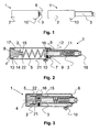
- FIG. 1 For example, an embodiment of the safety device 1 according to the invention with a cylinder-like housing part 2 and a suction tube 3 is shown.
- the suction tube 3 is displaceable in the axial direction and movably guided in a passage in the front wall 6 of the cylinder-like housing part 2.
- the suction pipe 3 In the left picture of the FIG. 1 the suction pipe 3 is located in the housing part 2.
- the right figure shows the safety gear 1 with fully extended suction pipe. 3
- FIG. 2 shows a cross section through the longitudinal axis of the safety gear 1.
- a piston 4 is arranged, which is operatively connected via a resilient element, such as a compression spring 5 with the bottom 7 of the suction tube 3.
- the relaxed spring 5 pushes the piston 4 and the suction tube 3 aurder, so that the piston 4 on the rear housing wall 8 and the bottom 7 of the suction tube 3 rests against the front housing wall 6.
- the suction tube 3 is guided in the passage 9 of the front housing wall 6.
- the bottom 7 of the suction tube 3 has an inner diameter which corresponds approximately to the inner diameter of the housing 2, so that the suction tube 3 is displaceable in the axial direction, without tilting.
- a longitudinally extending web 11 is arranged, which engages in a recess 12 in the passage 9 of the front housing wall 6.
- the punch-shaped piston 4 has a diameter which corresponds approximately to the inner diameter of the cylindrical piston housing 2.
- a seated in an annular groove 14 in the piston 4 seal 13 is characterized sealingly against the inner wall of the piston housing 2.
- the piston 4 is graduated suction pipe side and ends in a nipple 15 which forms a locking means which is provided for locking in a arranged in the bottom part 7 of the suction tube 3 holding device with a lock 16.
- the holding device is formed by a slide 26 which is guided in a run perpendicular to the longitudinal axis slot 25 and, spring-loaded.
- the slider 26 has a hole for receiving the nipple 15 and is intended to engage in the groove 22 of the nipple 15.
- the first step in the piston 4 forms a shoulder 17, which serves to receive the compression spring 5.
- a removable catcher 18 is arranged for receiving the insects to be caught.
- a shutter designed as a push button 10 can be seen. In the illustrated position, which shows the state after a capture process, the suction pipe 3 is maximally extended and the piston 4 is located at the rear end of the piston housing second
- FIG. 3 is a cross section through the longitudinal axis of the safety gear 1 with tensioned compression spring 5 is shown.
- the suction tube 3 is pushed against the spring force of the compression spring 5 in the housing 2.
- the latch 16 arranged in the holding device snaps into an annular groove 22 in the nipple 15.
- the piston 4 under the tension of the compression spring 5 is held together with the suction tube 3.
- the suction tube 3 is located almost entirely in the housing 2. Only the foremost part of the suction tube 3 protrudes from the front cylinder wall 6.
- the lock 16 Since in this position, the lock 16 is not accessible from the outside, it can not be solved.
- the safety gear 1 is indeed tense but still secured. If the intake manifold 3 is pulled axially out of the housing 2, then the piston 4 connected and locked to the intake manifold 3 via the holding device 16 likewise moves in the direction of the front cylinder wall 6. The capture process can then be triggered when the piston 4 engages the bottom 7 of the suction tube 3 in the housing 2 are positioned so that the lock 16 is actuated by the trigger.
- a stop 34 is provided on the inside of the housing wall in the region of the trigger 10, to which the slider 26 is present as soon as the suction tube 3 is fully extended. By pressing the trigger 10, the holding device is unlocked and triggered the catching process.
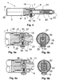
- FIG. 4 shows the safety device in a cross section through the longitudinal axis with a tensioned compression spring in the locked release position.
- the trigger 10 and the stop 34 are arranged on the housing 2 so that the bottom 7 of the suction tube 3 does not touch the front cylinder wall 6 in this position. Now, if the trigger 10 is pressed for a catch, the lock 16 is released and the suction tube 3 speeds forward on the one hand until the bottom 7 of the suction tube 3 is present on the inside of the front cylinder wall 6, and on the other hand, the piston 4 speeds towards the rear housing wall 8.
- the wires are funnel-shaped inward and directed against the longitudinal axis and form a kind of barbs, so that an insect sucked in can not escape from the catcher.
- a sieve 24 is provided, so that the insect is not sucked into the housing.
- the arranged in the front region of the suction pipe 3 catcher 18 is shock-damped with a support spring 31. This means that the catcher 18 can be pressed against the spring force of the spring 31 in the intake manifold 3. If the catch container 18 is unloaded again in the axial direction, it is pushed back by the intercepting spring into its original position.
- This shock absorption has the task of intercepting a shock through the suction tube 3 to an object or object, if the safety gear 1 was held with the suction tube 3 when triggering a fishing process too close to a solid object. This can be used to prevent injuries to persons or damage to objects.
- FIG. 5a shows a partial view of a cross section through the longitudinal axis of the safety gear 1 in the region of the holding device or the trigger 10 in the locked position.
- the nipple 15 is located in the piston-side opening 21 of the suction pipe 3.
- the edge of the opening 21 has a funnel-shaped chamfer.
- the nipple 15 is tapered in a truncated cone at its front end. This ensures that when inserting the nipple 15 in the opening 21 of the nipple 15 automatically centered in the opening 21 of the suction tube 3.
- the bottom 7 of the suction tube 3 has a perpendicular to the longitudinal axis slot 25, in which a slider 26 is inserted.
- FIG. 5b is a cross section perpendicular to the longitudinal axis of the safety gear in the region of the holding device in the locked position represented, in which the details of the holding device can be seen.
- a blind hole 32 is provided, in which a compression spring 27 is inserted. This spring 27 presses the slider against the inner wall of the housing 2.
- the hole 33 in the slider 26 is decentered with respect to the longitudinal axis of the piston 4 and the suction tube.
- FIGS. 5a and 5b show the same partial views as the FIGS. 5a and 5b , with the difference that the spring-loaded with spring 35 push button 10 is pressed, whereby the pin 29 pushes the slider 26 against the spring pressure of the spring 27 from the groove 22 in the nipple 15.
- the holding device 16 is unlocked and the piston 4 is no longer held together with the suction tube 3.
- the suction pipe 3 and the piston 4 are pressed in opposite directions from each other.
- the air channel 36 connects the suction tube 3 with the interior of the piston housing 2 and allows that during the capture process immediately after triggering already air from the suction tube 3 can be sucked, although the nipple 15 still covers part of the opening 21.
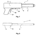
- FIG. 7 shows a further embodiment of the inventive safety gear 1.
- a pistol-like handle 37 is arranged with a trigger 38.
- the trigger 10 is actuated via a rocker arm 39.
- FIG. 8 shown expedient development of the invention is that the suction tube 3 is formed in the form of a telescopic tube 40.
- a device equipped with such a telescopic tube 40 locations within a room can be achieved, which are usually not accessible without aids, such. As the corners between the ceiling and the walls of living spaces.
- the device according to the invention is thus much simpler and smaller in its construction and overall safe in its application and mode of operation in comparison with known devices.
Landscapes
- Life Sciences & Earth Sciences (AREA)
- Pest Control & Pesticides (AREA)
- Engineering & Computer Science (AREA)
- Insects & Arthropods (AREA)
- Wood Science & Technology (AREA)
- Zoology (AREA)
- Environmental Sciences (AREA)
- Catching Or Destruction (AREA)
- Micro-Organisms Or Cultivation Processes Thereof (AREA)
Abstract
Description
Die Erfindung betrifft eine Vorrichtung zum Fangen von Insekten, Spinnen und anderer derartiger Kleintiere gemäß einem Teil des Patentanspruches 1.The invention relates to a device for catching insects, spiders and other such small animals according to one part of
Bisher bekannt gewordene Methoden der Entfernung von Insekten und Spinnen aus dem Lebensumfeld des Menschen sind beispielsweise die Fliegenklatsche und die Leimrute, die jedoch aus hygienischen Gesichtspunkten eher fragwürdige Instrumente zum Beseitigen von Insekten darstellen. Im Handel sind Sprühdosen und Pulver z.B. mit Insektiziden speziell gegen fliegende oder kriechende Insekten erhältlich, eine umweltbelastende, aber verbreitete Tötungsmethode. Insektizide stellen bei unsachgemäßer und häufiger Anwendung in bewohnten Räumen ein nicht zu vernachlässigendes Gesundheitsrisiko auch für den Menschen dar. Nach einer anderen modernen Methode werden angelockte fliegende Insekten in speziellen Geräten mittels elektrischem Strom getötet. Bekannt sind auch kleine elektrisch betriebene Tischsauger, die auch zum Einsaugen von Insekten und Spinnen verwendet werden. Mitunter kann man zwar einen üblichen Staubsauger einsetzen, aber das ist zeitraubend, umständlich und oft bedenklich, da beispielsweise von Lebensmitteln das Absaugen mit einem Staubsauger sehr unhygienisch ist.Previously known methods of removing insects and spiders from the living environment of humans are, for example, the fly swatter and the glue rod, but from a hygiene point of view rather questionable instruments for eliminating insects. In the trade, aerosols and powders are e.g. with insecticides especially against flying or crawling insects available, a polluting but common killing method. Insecticides, when used improperly and frequently in inhabited areas, represent a not insignificant health risk for humans as well. According to another modern method, attracted flying insects in special devices are killed by electric current. Also known are small electrically powered table vacuums, which are also used for sucking insects and spiders. Sometimes you can use a conventional vacuum cleaner, but this is time consuming, cumbersome and often questionable, because, for example, of food, the suction with a vacuum cleaner is very unhygienic.
Eine weitere Lösung liefern Geräte mit einem Impulssauger und daran angeschlossener Saugdüse. Dabei wird von der Erkenntnis ausgegangen, dass man sich z. B. einer Fliege mit dem Finger meist bis auf etwa 1 cm nähern kann, bevor sie wegfliegt. Eine zum Aufsaugen einer Fliege erforderliche Saugdüse hat etwa eine Querschnittsabmessungen eines Fingers oder Daumens, und man braucht nur einen kurzen impulsartige Saugstoss auszuüben, um bei kurzer Entfernung das Objekt einzusaugen.Another solution is provided by devices with an impulse aspirator and suction nozzle connected to it. It is based on the knowledge that z. B. a fly with the finger can usually approach to about 1 cm before flying away. A suction nozzle required for sucking a fly has about a cross-sectional dimensions of a finger or thumb, and one need only a short pulse-like sucking impulse to suck in at a short distance, the object.
Eine Vorrichtung dieser Art ist aus der
Einen weitergebildeten Impulssauger offenbart die G 91 16 394.3, bei dem die federelastischen Spannelemente zwischen der Rückseite des Kolbens und dem Bodenteil des Hohlzylinders angeordnet sind. Der Kolben ist auf der Rückseite mit einer zur Führung des Kolbens und zur Spannung der federelastischen Spannelemente dienenden Führungsstange verbunden. Dadurch wird erreicht, dass die mit dem Kolben verbundene Führungsstange für eine sichere Führung des Kolbens sorgt. Gleichzeitig dient sie als Spannorgan für die Zugfedern, indem sie mit einem Spannhebel versehen ist. Der Nachteil dieser Anordnung ist der komplexe Aufbau und die Baulänge des Impulssaugers, die sich aus der Länge des Saugrohrs, der Länge des Zylinders und der Länge des Griffs mit Spannhebel ergibt.A further developed impulse suction disclosed the G 91 16 394.3, in which the resilient clamping elements between the back of the piston and the bottom part of the hollow cylinder are arranged. The piston is connected on the back with a guide rod for guiding the piston and for tensioning the elastic tensioning elements. This ensures that the guide rod connected to the piston ensures safe guidance of the piston. At the same time, it serves as a tension member for the tension springs, by being provided with a tension lever. The disadvantage of this arrangement is the complex construction and the length of the pulse sucker, which results from the length of the suction tube, the length of the cylinder and the length of the handle with clamping lever.
Der vorliegenden Erfindung liegt die Aufgabe zugrunde, diese Nachteile bekannter Vorrichtungen zum Fangen von Insekten, Spinnen und anderer derartiger Kleintiere zu beseitigen.The present invention has for its object to overcome these disadvantages of known devices for catching insects, spiders and other such small animals.
Diese Aufgabe wird von einem lmpulssauger durch die Merkmale des Patentanspruchs 1 gelöst.This object is achieved by a pulse sucker by the features of
Bei der erfindungsgemässen Vorrichtung ist ein federelastisches Element, beispielsweise eine Druckfeder zwischen dem Kolben und dem Bodenteil des Saugrohrs in einem Hohlzylinder angeordnet. Das mit dem Kolben über das federelastische Element wirkverbundene Saugrohr ist in axialer Richtung verschiebbar und in einer Durchführung der vorderen Zylinderwand beweglich gehalten. Der Kolben weist saugrohrseitig Rastmittel auf, die zum Einrasten in einer dafür im Bodenteil des Saugrohrs angeordneten Aufnahme vorgesehenen sind, und die über einen von aussen bedienbaren Auslösemechanismus lösbar sind. Zur Betätigung, das heisst zum Spannen des Impulssaugers wird das Saugrohr in den Zylinder geschoben und gegen die Druckkraft des federelastischen Elements in Richtung Zylinderboden gedrückt bis das Rastmittel des Kolbens in der Haltevorrichtung im Bodenteil des Saugrohres einreiste. Zum Auslösen, das heisst zum Fangen eines Insekts wird das Saugrohr aus dem Zylinder gezogen und der mit dem Saugrohr über das federelastische Element verbundene Kolben in Richtung vordere Zylinderwand geschoben, so dass die Auslösevorrichtung mit dem Rastmittel in Eingriff kommt und durch Betätigen des Auslösers die Haltevorrichtung entriegelt. Aufgrund der Druckkraft des federelastischen Elementes wird nun einerseits das Saugrohr noch weiter aus dem Zylinder geschoben, bis der Bodenteil des Saugrohrs an der Innenseite der vorderen Zylinderwand ansteht, und andererseits wird der Kolben in Richtung Zylinderboden gedrückt. Dadurch entsteht im Zylinderraum zwischen dem Kolben und dem Bodenteil des Saugrohres ein Unterdruck, wodurch Luft durch das Saugrohr eingesogen wird. Dieser Luftstrom saugt ein vor dem Saugrohr befindliches Insekt in den im vorderen Bereich des Saugrohrs angeordneten Fangraum. Mit der erfindungsgemässen Vorrichtung wird zum einen erreicht, dass sich das Saugrohr beim Auslösen des Fangvorgangs dem zu fangenden Objekt noch nähert, was eine erhöhte Fangsicherheit gibt, und zum anderen kann die Gesamtbaugrösse der Vorrichtung klein gehalten werden, da das Saugrohr bei Nichtgebrauch in den Zylinder geschoben werden kann. Ein weiterer Vorteil besteht darin, dass der Impulssauger nur ausgelöst werden kann, wenn das Saugrohr in der Vorrichtung entsprechend positioniert ist, so dass die Auslösevorrichtung entriegelbar ist, was eine erhöhte Sicherheit im Umgang mit dem Impulssauger zur Folge hat.In the device according to the invention, a spring-elastic element, for example a compression spring, is arranged between the piston and the bottom part of the suction tube in a hollow cylinder. The suction pipe operatively connected to the piston via the resilient element is displaceable in the axial direction and movably held in a passage of the front cylinder wall. The piston has suction pipe side locking means, which are provided for locking in a arranged in the bottom part of the suction tube recording, and which are releasable via a triggering mechanism operable from the outside. For actuation, that is, for tensioning the impulse suction, the suction tube is pushed into the cylinder and pressed against the pressure force of the resilient element in the direction of the cylinder base until the locking means of the piston in the holding device in the bottom part of the suction tube entered. To trigger, that is to catch an insect, the suction pipe is pulled out of the cylinder and the piston connected to the suction tube via the resilient element pushed towards the front cylinder wall, so that the triggering device engages with the locking means and by pressing the trigger, the holding device unlocked. Due to the pressure force of the resilient element, on the one hand, the suction pipe is now pushed further out of the cylinder until the bottom part of the suction pipe is present on the inside of the front cylinder wall, and on the other hand, the piston is pressed in the direction of the cylinder base. This creates a negative pressure in the cylinder space between the piston and the bottom part of the intake manifold, whereby air is sucked through the intake manifold. This air stream sucks an insect located in front of the suction pipe into the catching space arranged in the front region of the suction pipe. With the device according to the invention, on the one hand, it is achieved the suction pipe still approaches the object to be caught when the catching process is triggered, which gives increased safety in catching, and secondly, the overall size of the device can be kept small since the suction pipe can be pushed into the cylinder when not in use. Another advantage is that the impulse aspirator can only be triggered when the suction pipe is positioned in the device accordingly, so that the triggering device can be unlocked, which has an increased safety in dealing with the Impulse sucker result.
Weitere Vorteile der Erfindung folgen aus den abhängigen Patentansprüchen und aus der nachfolgenden Beschreibung, in welcher die Erfindung anhand von in den Zeichnungen dargestellten Ausführungsbeispielen näher erläutert wird.Further advantages of the invention follow from the dependent claims and from the following description in which the invention with reference to embodiments shown in the drawings is explained in more detail.
Es zeigen:
- Fig. 1
- das Gehäuse der Fangvorrichtung mit eingeschobenem bzw. ausgefahrenem Saugrohr;
- Fig. 2
- einen Querschnitt durch die Längsachse der Fangvorrichtung mit entspannter Druckfeder;
- Fig.3
- einen Querschnitt durch die Längsachse der Fangvorrichtung mit gespannter Druckfeder in gesicherter Position;
- Fig.4
- einen Querschnitt durch die Längsachse der Fangvorrichtung mit gespannter Druckfeder in verriegelter Auslöseposition;
- Fig. 5a
- eine Teilansicht eines Querschnitts durch die Längsachse der Fangvor- richtung im Bereich der Haltevorrichtung in verriegelter Position;
- Fig. 5b
- einen Querschnitt senkrecht zur Längsachse der Fangvorrichtung im Bereich der Haltevorrichtung in verriegelter Position;
- Fig.6a
- eine Teilansicht eines Querschnitts durch die Längsachse der Fangvorrichtung im Bereich der Haltevorrichtung in entriegelter Position;
- Fig. 6b
- einen Querschnitt senkrecht zur Längsachse der Fangvorrichtung im Bereich der Haltevorrichtung in entriegelter Position;
- Fig. 7
- die Fangvorrichtung mit, einem am Gehäuse angeordneten pistolen- artigen Griff mit Abzughebel;
- Fig. 8
- eine Ausführung der Fangvorrichtung mit einem Saugrohr in Form eines Teleskoprohres.
- Fig. 1
- the housing of the safety gear with inserted or extended intake manifold;
- Fig. 2
- a cross section through the longitudinal axis of the safety gear with a relaxed compression spring;
- Figure 3
- a cross section through the longitudinal axis of the safety gear with tensioned compression spring in a secured position;
- Figure 4
- a cross section through the longitudinal axis of the safety gear with tensioned compression spring in locked release position;
- Fig. 5a
- a partial view of a cross section through the longitudinal axis of the catching device in the region of the holding device in the locked position;
- Fig. 5b
- a cross section perpendicular to the longitudinal axis of the safety gear in the region of the holding device in the locked position;
- 6a
- a partial view of a cross section through the longitudinal axis of the safety gear in the region of the holding device in the unlocked position;
- Fig. 6b
- a cross section perpendicular to the longitudinal axis of the safety gear in the region of the holding device in the unlocked position;
- Fig. 7
- the catching device with a pistol-like handle with pull-off lever arranged on the housing;
- Fig. 8
- an embodiment of the safety gear with a suction tube in the form of a telescopic tube.
In den Figuren sind für dieselben Elemente jeweils dieselben Bezugszeichen verwendet worden und erstmalige Erklärungen betreffen alle Figuren, wenn nicht ausdrücklich anders erwähnt.In the figures, the same reference numerals have been used for the same elements and first explanations apply to all figures, unless expressly stated otherwise.
In der
Die
In
Die
Die
In der
Die
Die
Eine in
Die erfindungsgemässe Vorrichtung ist also im Vergleich mit bekannten Vorrichtungen wesentlich einfacher und kleiner in ihrem Aufbau und insgesamt sicher in ihrer Anwendung und Wirkungsweise.The device according to the invention is thus much simpler and smaller in its construction and overall safe in its application and mode of operation in comparison with known devices.
Claims (10)
- A device for catching insects, spiders, and other small animals of this type using a pulse suction unit (1), containing a cylindrical housing part (2), a piston (4), a suction tube (3), and a spring-elastic element (5), the spring-elastic element (5) being formed by a compression spring, which is situated between the piston (4) and the suction tube (3) in the interior of the cylindrical housing part (2), and the suction tube (3), which is operationally linked to the piston (4) via the compression spring (5), being guided so it is displaceable in the axial direction in a passage (9) in the front wall (6) of the cylindrical housing part (2), and the piston (4) having detent means (15, 22) on the suction tube side, which are provided to engage in a retention device, situated for this purpose in the floor part (7) of the section tube (3), having a lock (16), and which are unlockable via an externally operable actuator (10).
- The device according to Claim 1, characterized in that the detent means are formed by a nipple (15), which is situated on the suction tube side on the piston (4), having an annular groove (22).
- The device according to Claim 2, characterized in that the retention device (16) contains a spring-loaded slide (26), which is guided in a slot (25) running perpendicular to the longitudinal axis of the device, and which has a hole (33), which is intended to receive the nipple (15), furthermore, a pocket hole (32) having a compression spring (27) is provided in the floor of the slot (25), which presses the slide (26) against the inner wall of the housing (2).
- The device according to Claim 2, characterized in that the nipple (15) has an axially running longitudinal hole, which opens into a transverse hole running perpendicular thereto, so that these two holes form an air channel (36).
- The device according to one of the preceding claims, characterized in that a web (11), running in the longitudinal direction, is situated on the top side of the suction tube (3), which engages in a recess (12) in the passage (9) of the front housing wall (6).
- The device according to one of the preceding claims, characterized in that a removable capture container (18), having a weir closure (23) on its mouth, is situated in the front end area of the suction tube (3).
- The device according to Claim 6, characterized in that the capture container (18) is cushioned in the longitudinal direction using an intercepting spring (31).
- The device according to one of the preceding claims, characterized in that a pistol grip (37) having a trigger lever (38) and a rocker lever (39) for actuating the actuator (10) is situated on the housing (2) of the capture device (1).
- The device according to one of the preceding claims, characterized in that the suction tube (3) is implemented in the form of a telescoping tube (40).
- The device according to one of the preceding claims, characterized in that the actuator (10) is positioned on the housing (2) in such a way that the floor (7) of the suction tube (3) is movable in the direction toward the front housing wall upon triggering of a capture action.
Applications Claiming Priority (2)
| Application Number | Priority Date | Filing Date | Title |
|---|---|---|---|
| CH9272006 | 2006-06-08 | ||
| PCT/CH2007/000263 WO2007140636A1 (en) | 2006-06-08 | 2007-05-24 | Device for catching insects, spiders and other small animals of this type |
Publications (2)
| Publication Number | Publication Date |
|---|---|
| EP2023716A1 EP2023716A1 (en) | 2009-02-18 |
| EP2023716B1 true EP2023716B1 (en) | 2009-08-26 |
Family
ID=38519665
Family Applications (1)
| Application Number | Title | Priority Date | Filing Date |
|---|---|---|---|
| EP07720160A Not-in-force EP2023716B1 (en) | 2006-06-08 | 2007-05-24 | Device for catching insects, spiders and other small animals of this type |
Country Status (8)
| Country | Link |
|---|---|
| US (1) | US8074395B2 (en) |
| EP (1) | EP2023716B1 (en) |
| CN (1) | CN101466261B (en) |
| AT (1) | ATE440496T1 (en) |
| DE (1) | DE502007001418D1 (en) |
| ES (1) | ES2331666T3 (en) |
| HK (1) | HK1130156A1 (en) |
| WO (1) | WO2007140636A1 (en) |
Families Citing this family (16)
| Publication number | Priority date | Publication date | Assignee | Title |
|---|---|---|---|---|
| US8276313B2 (en) | 2003-09-17 | 2012-10-02 | Gerd Reime | Method and apparatus for trapping insects |
| ES2302636B1 (en) * | 2006-11-30 | 2009-05-21 | Consejo Superior Investig. Cienficas | EQUIPMENT FOR THE ASEPTIC HANDLING OF LABORATORY ANIMALS. |
| US20120311921A1 (en) * | 2009-08-20 | 2012-12-13 | Ogilvie John W | Kinetic non-adhesive pest control amusement devices and methods |
| US20140047759A1 (en) * | 2012-08-15 | 2014-02-20 | Charles Almy | Bug catching device |
| CN103287779B (en) * | 2013-06-04 | 2016-04-13 | 无锡明珠钢球有限公司 | Simple steel ball picking-up machine |
| CN105532612B (en) * | 2014-04-14 | 2018-04-17 | 张福谦 | A kind of hydrocone type fly or mosquito pick-up unit |
| CN103931586B (en) * | 2014-04-14 | 2016-08-17 | 慈溪市桥头京姬电子元件厂 | A kind of sucking type fly or mosquito pick-up unit |
| CN103918626B (en) * | 2014-04-14 | 2016-09-14 | 慈溪市宝日电器有限公司 | A kind of fly or mosquito pick-up unit |
| CN104488842A (en) * | 2014-12-24 | 2015-04-08 | 吕皓 | Negative pressure type mosquito killer |
| US10881094B2 (en) | 2017-10-11 | 2021-01-05 | Tony Guo | Insect vacuum and trap attachment systems |
| CN108782502B (en) * | 2018-05-22 | 2021-06-08 | 曾钰翔 | Insect trap |
| CN109497016A (en) * | 2018-12-20 | 2019-03-22 | 贵州师范大学 | A kind of multifunctional ceiling scolite |
| CN110250128B (en) * | 2019-06-26 | 2024-04-26 | 建德市艾格电器有限公司 | Insect sucking device |
| US11363809B2 (en) * | 2020-01-22 | 2022-06-21 | Paul Gangarosa | Insect vacuum device |
| CN111493040B (en) * | 2020-06-15 | 2021-09-07 | 浙江陶氏集团黄岩模具二厂有限公司 | Environment-friendly mosquito killing device |
| CN112388372B (en) * | 2020-09-23 | 2021-12-28 | 宁波高新区利威科技有限公司 | Clamping and discharging mechanism |
Family Cites Families (12)
| Publication number | Priority date | Publication date | Assignee | Title |
|---|---|---|---|---|
| DE270634C (en) * | 1912-02-26 | |||
| US1141039A (en) * | 1915-04-20 | 1915-05-25 | Robert Hanham Cox | Fly-trap. |
| US3965608A (en) * | 1972-07-10 | 1976-06-29 | Mark Schuman | Manually operated suction device for capturing small objects |
| DE3225330A1 (en) | 1982-07-07 | 1984-01-12 | Jochen Reinhold 5910 Kreuztal Zoz | DEVICE FOR SUCTIONING INDIVIDUAL OBJECTS, IN PARTICULAR INSECTS, FLIES, WASPS, AND THE LIKE |
| US4733495A (en) * | 1987-05-21 | 1988-03-29 | James Winnicki | Flying insect exterminator |
| DE9116394U1 (en) | 1991-05-31 | 1992-09-03 | Arned Gesellschaft Fuer Die Entwicklung Von Produktneuheiten Mbh, 5180 Eschweiler, De | |
| DE4327150A1 (en) * | 1993-08-12 | 1995-02-16 | Heinz Peter Brandstetter | Method and device for catching insects |
| US5367821A (en) * | 1993-10-18 | 1994-11-29 | Ott; Gary D. | Suction insect trap apparatus |
| US7014622B1 (en) * | 1999-02-18 | 2006-03-21 | Medsafe Technologies, Llc | Interchangeable needle safety syringe |
| JP2003092963A (en) * | 2001-09-25 | 2003-04-02 | Ryoichi Morimoto | Suction type insect capturing tool |
| CN2722637Y (en) * | 2004-04-15 | 2005-09-07 | 陶章菊 | Fly killing gun |
| US20050246945A1 (en) * | 2004-05-10 | 2005-11-10 | David Evink | Insect capturing device |
-
2007
- 2007-05-24 EP EP07720160A patent/EP2023716B1/en not_active Not-in-force
- 2007-05-24 DE DE502007001418T patent/DE502007001418D1/en active Active
- 2007-05-24 CN CN2007800211617A patent/CN101466261B/en not_active Expired - Fee Related
- 2007-05-24 WO PCT/CH2007/000263 patent/WO2007140636A1/en active Application Filing
- 2007-05-24 ES ES07720160T patent/ES2331666T3/en active Active
- 2007-05-24 US US12/303,478 patent/US8074395B2/en not_active Expired - Fee Related
- 2007-05-24 AT AT07720160T patent/ATE440496T1/en active
-
2009
- 2009-10-08 HK HK09109338.3A patent/HK1130156A1/en not_active IP Right Cessation
Also Published As
| Publication number | Publication date |
|---|---|
| ATE440496T1 (en) | 2009-09-15 |
| CN101466261B (en) | 2010-12-22 |
| US20090313884A1 (en) | 2009-12-24 |
| WO2007140636A1 (en) | 2007-12-13 |
| HK1130156A1 (en) | 2009-12-24 |
| DE502007001418D1 (en) | 2009-10-08 |
| CN101466261A (en) | 2009-06-24 |
| US8074395B2 (en) | 2011-12-13 |
| ES2331666T3 (en) | 2010-01-12 |
| EP2023716A1 (en) | 2009-02-18 |
Similar Documents
| Publication | Publication Date | Title |
|---|---|---|
| EP2023716B1 (en) | Device for catching insects, spiders and other small animals of this type | |
| DE102009049429B4 (en) | sliding arrangement | |
| EP2575587B1 (en) | Vacuum cleaner with counter flow filter cleaning | |
| EP1720591B1 (en) | Atomiser | |
| DE2549477B2 (en) | Pipetting device | |
| DE102012211246A1 (en) | Combination of a small vacuum cleaner and a stem vacuum cleaner frame as well as small vacuum cleaner and handle vacuum cleaner frame | |
| DE2903667A1 (en) | ARROW LAUNCHER AND ARROW | |
| WO1984000280A1 (en) | Apparatus for sucking isolated objects, for example insects, flies, wasps, etc | |
| DE4327150A1 (en) | Method and device for catching insects | |
| EP3456195A1 (en) | Swatter | |
| EP2866632B1 (en) | Combination made up of a small vacuum cleaner and of an upright vacuum cleaner frame, and small vacuum cleaner and upright vacuum cleaner frame | |
| DE4112266C1 (en) | Insect exhauster with piston in pump cylinder - has suction pipe with valve flap, opening in blow-out sense on air expelling from pump cylinder | |
| EP0510472B1 (en) | Collector for animal excrement | |
| DE102011113859B3 (en) | Striking and catching device for use in household for striking and catching e.g. flies, has striking part and container adjacently arranged at front suction end and connected with suction end, where insects are sucked through inlet opening | |
| DE2106982C2 (en) | Desoldering device | |
| DE19636247A1 (en) | Insect capturing equipment for use in living areas | |
| DE940436C (en) | Method and pistol-like device for killing flies or the like. | |
| DE102005030502B4 (en) | Insect trapping device | |
| DE102019102849A1 (en) | Suction nozzle for a vacuum cleaner, preferably as an attachment | |
| DE19946707C2 (en) | Suction device for suctioning liquid supernatants from open containers | |
| DE202004001323U1 (en) | Insect trap has vacuum pump and suction pipe drawing insect into vacuum container | |
| DE8219398U1 (en) | DEVICE FOR SUCTIONING INDIVIDUAL OBJECTS, EXAMPLE INSECTS, FLIES, WASPS AND THE LIKE | |
| DE202017107648U1 (en) | Suction holder for vacuum suction | |
| DE4322460A1 (en) | Insect trap housing - consists of case with cover fixed to end of tube and has drawer inside case fixed to end of rod with grip handle | |
| DE626148C (en) | Display device on vacuum cleaners |
Legal Events
| Date | Code | Title | Description |
|---|---|---|---|
| PUAI | Public reference made under article 153(3) epc to a published international application that has entered the european phase |
Free format text: ORIGINAL CODE: 0009012 |
|
| 17P | Request for examination filed |
Effective date: 20081127 |
|
| AK | Designated contracting states |
Kind code of ref document: A1 Designated state(s): AT BE BG CH CY CZ DE DK EE ES FI FR GB GR HU IE IS IT LI LT LU LV MC MT NL PL PT RO SE SI SK TR |
|
| AX | Request for extension of the european patent |
Extension state: AL BA HR MK RS |
|
| GRAP | Despatch of communication of intention to grant a patent |
Free format text: ORIGINAL CODE: EPIDOSNIGR1 |
|
| GRAS | Grant fee paid |
Free format text: ORIGINAL CODE: EPIDOSNIGR3 |
|
| GRAA | (expected) grant |
Free format text: ORIGINAL CODE: 0009210 |
|
| AK | Designated contracting states |
Kind code of ref document: B1 Designated state(s): AT BE BG CH CY CZ DE DK EE ES FI FR GB GR HU IE IS IT LI LT LU LV MC MT NL PL PT RO SE SI SK TR |
|
| REG | Reference to a national code |
Ref country code: GB Ref legal event code: FG4D Free format text: NOT ENGLISH |
|
| REG | Reference to a national code |
Ref country code: CH Ref legal event code: EP |
|
| REG | Reference to a national code |
Ref country code: CH Ref legal event code: NV Representative=s name: SPIERENBURG & PARTNER AG, PATENT- UND MARKENANWAEL Ref country code: IE Ref legal event code: FG4D Free format text: LANGUAGE OF EP DOCUMENT: GERMAN |
|
| REF | Corresponds to: |
Ref document number: 502007001418 Country of ref document: DE Date of ref document: 20091008 Kind code of ref document: P |
|
| REG | Reference to a national code |
Ref country code: ES Ref legal event code: FG2A Ref document number: 2331666 Country of ref document: ES Kind code of ref document: T3 |
|
| LTIE | Lt: invalidation of european patent or patent extension |
Effective date: 20090826 |
|
| PG25 | Lapsed in a contracting state [announced via postgrant information from national office to epo] |
Ref country code: SE Free format text: LAPSE BECAUSE OF FAILURE TO SUBMIT A TRANSLATION OF THE DESCRIPTION OR TO PAY THE FEE WITHIN THE PRESCRIBED TIME-LIMIT Effective date: 20090826 Ref country code: IS Free format text: LAPSE BECAUSE OF FAILURE TO SUBMIT A TRANSLATION OF THE DESCRIPTION OR TO PAY THE FEE WITHIN THE PRESCRIBED TIME-LIMIT Effective date: 20091226 Ref country code: LT Free format text: LAPSE BECAUSE OF FAILURE TO SUBMIT A TRANSLATION OF THE DESCRIPTION OR TO PAY THE FEE WITHIN THE PRESCRIBED TIME-LIMIT Effective date: 20090826 Ref country code: FI Free format text: LAPSE BECAUSE OF FAILURE TO SUBMIT A TRANSLATION OF THE DESCRIPTION OR TO PAY THE FEE WITHIN THE PRESCRIBED TIME-LIMIT Effective date: 20090826 |
|
| NLV1 | Nl: lapsed or annulled due to failure to fulfill the requirements of art. 29p and 29m of the patents act | ||
| PG25 | Lapsed in a contracting state [announced via postgrant information from national office to epo] |
Ref country code: PL Free format text: LAPSE BECAUSE OF FAILURE TO SUBMIT A TRANSLATION OF THE DESCRIPTION OR TO PAY THE FEE WITHIN THE PRESCRIBED TIME-LIMIT Effective date: 20090826 Ref country code: SI Free format text: LAPSE BECAUSE OF FAILURE TO SUBMIT A TRANSLATION OF THE DESCRIPTION OR TO PAY THE FEE WITHIN THE PRESCRIBED TIME-LIMIT Effective date: 20090826 Ref country code: LV Free format text: LAPSE BECAUSE OF FAILURE TO SUBMIT A TRANSLATION OF THE DESCRIPTION OR TO PAY THE FEE WITHIN THE PRESCRIBED TIME-LIMIT Effective date: 20090826 Ref country code: NL Free format text: LAPSE BECAUSE OF FAILURE TO SUBMIT A TRANSLATION OF THE DESCRIPTION OR TO PAY THE FEE WITHIN THE PRESCRIBED TIME-LIMIT Effective date: 20090826 |
|
| PG25 | Lapsed in a contracting state [announced via postgrant information from national office to epo] |
Ref country code: CY Free format text: LAPSE BECAUSE OF FAILURE TO SUBMIT A TRANSLATION OF THE DESCRIPTION OR TO PAY THE FEE WITHIN THE PRESCRIBED TIME-LIMIT Effective date: 20090826 Ref country code: PT Free format text: LAPSE BECAUSE OF FAILURE TO SUBMIT A TRANSLATION OF THE DESCRIPTION OR TO PAY THE FEE WITHIN THE PRESCRIBED TIME-LIMIT Effective date: 20091228 Ref country code: BG Free format text: LAPSE BECAUSE OF FAILURE TO SUBMIT A TRANSLATION OF THE DESCRIPTION OR TO PAY THE FEE WITHIN THE PRESCRIBED TIME-LIMIT Effective date: 20091126 |
|
| REG | Reference to a national code |
Ref country code: IE Ref legal event code: FD4D |
|
| PG25 | Lapsed in a contracting state [announced via postgrant information from national office to epo] |
Ref country code: CZ Free format text: LAPSE BECAUSE OF FAILURE TO SUBMIT A TRANSLATION OF THE DESCRIPTION OR TO PAY THE FEE WITHIN THE PRESCRIBED TIME-LIMIT Effective date: 20090826 Ref country code: DK Free format text: LAPSE BECAUSE OF FAILURE TO SUBMIT A TRANSLATION OF THE DESCRIPTION OR TO PAY THE FEE WITHIN THE PRESCRIBED TIME-LIMIT Effective date: 20090826 Ref country code: IE Free format text: LAPSE BECAUSE OF FAILURE TO SUBMIT A TRANSLATION OF THE DESCRIPTION OR TO PAY THE FEE WITHIN THE PRESCRIBED TIME-LIMIT Effective date: 20090826 Ref country code: EE Free format text: LAPSE BECAUSE OF FAILURE TO SUBMIT A TRANSLATION OF THE DESCRIPTION OR TO PAY THE FEE WITHIN THE PRESCRIBED TIME-LIMIT Effective date: 20090826 Ref country code: RO Free format text: LAPSE BECAUSE OF FAILURE TO SUBMIT A TRANSLATION OF THE DESCRIPTION OR TO PAY THE FEE WITHIN THE PRESCRIBED TIME-LIMIT Effective date: 20090826 |
|
| PG25 | Lapsed in a contracting state [announced via postgrant information from national office to epo] |
Ref country code: SK Free format text: LAPSE BECAUSE OF FAILURE TO SUBMIT A TRANSLATION OF THE DESCRIPTION OR TO PAY THE FEE WITHIN THE PRESCRIBED TIME-LIMIT Effective date: 20090826 |
|
| PLBE | No opposition filed within time limit |
Free format text: ORIGINAL CODE: 0009261 |
|
| STAA | Information on the status of an ep patent application or granted ep patent |
Free format text: STATUS: NO OPPOSITION FILED WITHIN TIME LIMIT |
|
| 26N | No opposition filed |
Effective date: 20100527 |
|
| PG25 | Lapsed in a contracting state [announced via postgrant information from national office to epo] |
Ref country code: GR Free format text: LAPSE BECAUSE OF FAILURE TO SUBMIT A TRANSLATION OF THE DESCRIPTION OR TO PAY THE FEE WITHIN THE PRESCRIBED TIME-LIMIT Effective date: 20091127 |
|
| BERE | Be: lapsed |
Owner name: JANCIC, SILVIN M. Effective date: 20100531 |
|
| PG25 | Lapsed in a contracting state [announced via postgrant information from national office to epo] |
Ref country code: MC Free format text: LAPSE BECAUSE OF NON-PAYMENT OF DUE FEES Effective date: 20100531 |
|
| PG25 | Lapsed in a contracting state [announced via postgrant information from national office to epo] |
Ref country code: BE Free format text: LAPSE BECAUSE OF NON-PAYMENT OF DUE FEES Effective date: 20100531 Ref country code: IT Free format text: LAPSE BECAUSE OF NON-PAYMENT OF DUE FEES Effective date: 20100524 |
|
| PG25 | Lapsed in a contracting state [announced via postgrant information from national office to epo] |
Ref country code: MT Free format text: LAPSE BECAUSE OF FAILURE TO SUBMIT A TRANSLATION OF THE DESCRIPTION OR TO PAY THE FEE WITHIN THE PRESCRIBED TIME-LIMIT Effective date: 20090826 |
|
| PGFP | Annual fee paid to national office [announced via postgrant information from national office to epo] |
Ref country code: ES Payment date: 20110518 Year of fee payment: 5 |
|
| PG25 | Lapsed in a contracting state [announced via postgrant information from national office to epo] |
Ref country code: HU Free format text: LAPSE BECAUSE OF FAILURE TO SUBMIT A TRANSLATION OF THE DESCRIPTION OR TO PAY THE FEE WITHIN THE PRESCRIBED TIME-LIMIT Effective date: 20100227 Ref country code: LU Free format text: LAPSE BECAUSE OF NON-PAYMENT OF DUE FEES Effective date: 20100524 |
|
| PG25 | Lapsed in a contracting state [announced via postgrant information from national office to epo] |
Ref country code: TR Free format text: LAPSE BECAUSE OF FAILURE TO SUBMIT A TRANSLATION OF THE DESCRIPTION OR TO PAY THE FEE WITHIN THE PRESCRIBED TIME-LIMIT Effective date: 20090826 |
|
| REG | Reference to a national code |
Ref country code: AT Ref legal event code: MM01 Ref document number: 440496 Country of ref document: AT Kind code of ref document: T Effective date: 20120524 |
|
| PG25 | Lapsed in a contracting state [announced via postgrant information from national office to epo] |
Ref country code: AT Free format text: LAPSE BECAUSE OF NON-PAYMENT OF DUE FEES Effective date: 20120524 |
|
| REG | Reference to a national code |
Ref country code: ES Ref legal event code: FD2A Effective date: 20131021 |
|
| PG25 | Lapsed in a contracting state [announced via postgrant information from national office to epo] |
Ref country code: ES Free format text: LAPSE BECAUSE OF NON-PAYMENT OF DUE FEES Effective date: 20120525 |
|
| REG | Reference to a national code |
Ref country code: FR Ref legal event code: PLFP Year of fee payment: 10 |
|
| REG | Reference to a national code |
Ref country code: CH Ref legal event code: PCOW Free format text: NEW ADDRESS: ALTE BAHNHOFSTRASSE 5, 5612 VILLMERGEN (CH) |
|
| REG | Reference to a national code |
Ref country code: FR Ref legal event code: PLFP Year of fee payment: 11 |
|
| REG | Reference to a national code |
Ref country code: FR Ref legal event code: PLFP Year of fee payment: 12 |
|
| PGFP | Annual fee paid to national office [announced via postgrant information from national office to epo] |
Ref country code: CH Payment date: 20200407 Year of fee payment: 14 Ref country code: FR Payment date: 20200523 Year of fee payment: 14 Ref country code: DE Payment date: 20200526 Year of fee payment: 14 |
|
| PGFP | Annual fee paid to national office [announced via postgrant information from national office to epo] |
Ref country code: GB Payment date: 20200528 Year of fee payment: 14 Ref country code: IT Payment date: 20200529 Year of fee payment: 14 |
|
| REG | Reference to a national code |
Ref country code: DE Ref legal event code: R119 Ref document number: 502007001418 Country of ref document: DE |
|
| REG | Reference to a national code |
Ref country code: CH Ref legal event code: PL |
|
| GBPC | Gb: european patent ceased through non-payment of renewal fee |
Effective date: 20210524 |
|
| PG25 | Lapsed in a contracting state [announced via postgrant information from national office to epo] |
Ref country code: CH Free format text: LAPSE BECAUSE OF NON-PAYMENT OF DUE FEES Effective date: 20210531 Ref country code: LI Free format text: LAPSE BECAUSE OF NON-PAYMENT OF DUE FEES Effective date: 20210531 |
|
| PG25 | Lapsed in a contracting state [announced via postgrant information from national office to epo] |
Ref country code: GB Free format text: LAPSE BECAUSE OF NON-PAYMENT OF DUE FEES Effective date: 20210524 Ref country code: DE Free format text: LAPSE BECAUSE OF NON-PAYMENT OF DUE FEES Effective date: 20211201 |
|
| PG25 | Lapsed in a contracting state [announced via postgrant information from national office to epo] |
Ref country code: FR Free format text: LAPSE BECAUSE OF NON-PAYMENT OF DUE FEES Effective date: 20210531 |
|
| PG25 | Lapsed in a contracting state [announced via postgrant information from national office to epo] |
Ref country code: IT Free format text: LAPSE BECAUSE OF NON-PAYMENT OF DUE FEES Effective date: 20210531 |