EP2023665A1 - Hörereinrichtung mit beeinflussbarer Schallaustrittsrichtung - Google Patents
Hörereinrichtung mit beeinflussbarer Schallaustrittsrichtung Download PDFInfo
- Publication number
- EP2023665A1 EP2023665A1 EP08104695A EP08104695A EP2023665A1 EP 2023665 A1 EP2023665 A1 EP 2023665A1 EP 08104695 A EP08104695 A EP 08104695A EP 08104695 A EP08104695 A EP 08104695A EP 2023665 A1 EP2023665 A1 EP 2023665A1
- Authority
- EP
- European Patent Office
- Prior art keywords
- sound
- adapter
- receiver
- alignment element
- spherical alignment
- Prior art date
- Legal status (The legal status is an assumption and is not a legal conclusion. Google has not performed a legal analysis and makes no representation as to the accuracy of the status listed.)
- Granted
Links
Images


Classifications
-
- H—ELECTRICITY
- H04—ELECTRIC COMMUNICATION TECHNIQUE
- H04R—LOUDSPEAKERS, MICROPHONES, GRAMOPHONE PICK-UPS OR LIKE ACOUSTIC ELECTROMECHANICAL TRANSDUCERS; ELECTRIC HEARING AIDS; PUBLIC ADDRESS SYSTEMS
- H04R25/00—Electric hearing aids
- H04R25/65—Housing parts, e.g. shells, tips or moulds, or their manufacture
- H04R25/652—Ear tips; Ear moulds
- H04R25/656—Non-customized, universal ear tips, i.e. ear tips which are not specifically adapted to the size or shape of the ear or ear canal
-
- H—ELECTRICITY
- H04—ELECTRIC COMMUNICATION TECHNIQUE
- H04R—LOUDSPEAKERS, MICROPHONES, GRAMOPHONE PICK-UPS OR LIKE ACOUSTIC ELECTROMECHANICAL TRANSDUCERS; ELECTRIC HEARING AIDS; PUBLIC ADDRESS SYSTEMS
- H04R1/00—Details of transducers, loudspeakers or microphones
- H04R1/10—Earpieces; Attachments therefor ; Earphones; Monophonic headphones
- H04R1/1016—Earpieces of the intra-aural type
-
- H—ELECTRICITY
- H04—ELECTRIC COMMUNICATION TECHNIQUE
- H04R—LOUDSPEAKERS, MICROPHONES, GRAMOPHONE PICK-UPS OR LIKE ACOUSTIC ELECTROMECHANICAL TRANSDUCERS; ELECTRIC HEARING AIDS; PUBLIC ADDRESS SYSTEMS
- H04R25/00—Electric hearing aids
- H04R25/40—Arrangements for obtaining a desired directivity characteristic
- H04R25/402—Arrangements for obtaining a desired directivity characteristic using contructional means
-
- H—ELECTRICITY
- H04—ELECTRIC COMMUNICATION TECHNIQUE
- H04R—LOUDSPEAKERS, MICROPHONES, GRAMOPHONE PICK-UPS OR LIKE ACOUSTIC ELECTROMECHANICAL TRANSDUCERS; ELECTRIC HEARING AIDS; PUBLIC ADDRESS SYSTEMS
- H04R25/00—Electric hearing aids
- H04R25/65—Housing parts, e.g. shells, tips or moulds, or their manufacture
- H04R25/652—Ear tips; Ear moulds
Definitions
- the present invention relates to a hearing device for a hearing device with an ear piece for fixing the earpiece in an ear canal, a listener who has a preferred sound exit direction and an adapter for mounting the earpiece in the ear piece, wherein a sound of the listener is passed through the adapter.
- hearing device is understood in particular to mean a hearing device.
- the term includes other portable acoustic devices such as headsets, headphones and the like.
- Hearing aids are portable hearing aids that are used to care for the hearing impaired.
- different types of hearing aids such as behind-the-ear hearing aids (BTE), hearing aid with external receiver (RIC: receiver in the canal) and in-the-ear hearing aids (IDO), e.g. Concha hearing aids or canal hearing aids (ITE, CIC).
- BTE behind-the-ear hearing aids
- RIC hearing aid with external receiver
- IDO in-the-ear hearing aids
- ITE canal hearing aids
- the hearing aids listed by way of example are worn on the outer ear or in the ear canal.
- bone conduction hearing aids, implantable or vibrotactile hearing aids are also available on the market. The stimulation of the damaged hearing takes place either mechanically or electrically.
- Hearing aids have in principle as essential components an input transducer, an amplifier and an output transducer.
- the input transducer is usually a sound receiver, z. As a microphone, and / or an electromagnetic receiver, for. B. an induction coil.
- the output transducer is usually used as an electroacoustic transducer, z. As miniature speaker, or as an electromechanical transducer, z. B. bone conduction, realized.
- the amplifier is usually integrated in a signal processing unit. This principal Construction is in FIG. 1 shown using the example of a behind-the-ear hearing aid. In a hearing aid housing 1 for carrying behind the ear, one or more microphones 2 for receiving the sound from the environment are installed.
- a signal processing unit 3 which is also integrated in the hearing aid housing 1, processes the microphone signals and amplifies them.
- the output signal of the signal processing unit 3 is transmitted to a loudspeaker or earpiece 4, which outputs an acoustic signal.
- the sound is optionally transmitted via a sound tube, which is fixed with an earmold in the ear canal, to the eardrum of the device carrier.
- the power supply of the hearing device and in particular of the signal processing unit 3 is carried out by a likewise integrated into the hearing aid housing 1 battery. 5
- Hearing aids with external listeners are essentially designed such that a handset including a handset is interchangeably mounted in an individually shaped earmold.
- an adapter which receives an outstanding from the headset head element and thus attaches the earpiece in the earmold.
- the typical human ear canal has a sometimes more, sometimes less strongly curved entrance area. It is therefore advisable to use small and short handsets. Higher reinforcements, however, require long or large handset, which in total have a rigid long structure of the earmold result. Thus, there is a problem that due to the long construction of the earphone unit, no optimal adaptation to the auditory canal can be achieved. If the auditory canal is too curved, an individually shaped earmold with an external earphone is often dispensed with. Furthermore, difficulties arise when the sound generated by the listener in a strongly curved ear canal on a Wall of the ear canal to be issued. There is the disadvantage that the sound from the wall is too much attenuated.
- the object of the present invention is therefore to provide a receiver device for a hearing device in which a reliable adaptation to an auditory canal with regard to the sound outlet is made possible.
- the publication DE 10 2004 009 268 B3 discloses an earpiece for a handset system.
- the ear insert comprises a shaped body and a receiver, which is arranged removably in the molding.
- a sound outlet between the receiver and the side of the shaped body is formed, which faces the eardrum in the state in which the ear insert is inserted into an ear canal.
- the sound outlet is formed in a capsule and has the shape of an exponential horn.
- the publication DE 1 99 43 809 A1 discloses a hearing aid with an earmold, which forms a housing shell of the hearing aid and is produced after an impression of the external auditory canal of the user.
- the earmold contains a receiver, which converts an electrical signal into a sound wave.
- a neck body is provided, which is arranged on the eardrum-side inner end of the earmold.
- the attachment body protrudes into a space between the earmold and the eardrum of the ear canal.
- the attachment body is held by a connection tube, which is inserted at the inner end of the earmold and projects into a sound channel of the attachment body.
- the sound exit direction of the listener can be deflected in such a way that the sound is output by the earpiece at least approximately in the extension direction of the auditory canal.
- reflections of the sound on the walls of the ear canal are largely avoided and allows a barrier-free propagation of sound in the direction of the eardrum.
- the adapter is curved to redirect the preferred sound exit direction in the deviating direction.
- a curvature of the adapter can be designed with little effort and cost.
- a further advantage of the embodiment is that the curved shape of the adapter causes the sound signal output by the listener to be emitted particularly precisely in the direction of the auditory canal.
- the adapter may be bellows-shaped.
- a bellows-like configuration of the adapter makes it possible to variably adjust the curvature of the adapter and thus to further improve the adaptation.
- the curvature of the adapter can thus be designed individually, depending on the shape of the ear canal.
- the adapter is curved or bellows-shaped, wherein additionally a spherical alignment element, which has a continuous opening for the passage of sound, is pivotally mounted in the adapter, wherein the continuous opening of the spherical alignment element has a sound outlet opening of the earpiece, and wherein the spherical alignment element is adapted to deflect the sound from the preferred sound exit direction in the deviating direction.
- a spherical alignment element which has a continuous opening for the passage of sound, is pivotally mounted in the adapter, wherein the continuous opening of the spherical alignment element has a sound outlet opening of the earpiece, and wherein the spherical alignment element is adapted to deflect the sound from the preferred sound exit direction in the deviating direction.
- the spherical alignment member having the continuous opening for passing the sound may be pivotally mounted in the adapter alternatively to the curvature or to the bellows-like shape of the adapter, wherein the continuous opening of the spherical alignment element further forms the sound outlet opening of the ear piece and wherein the spherical Aligned element is designed to redirect the sound from the preferred sound exit direction in the deviating direction.
- This embodiment of the receiver device is particularly suitable for a less curved ear canal. Thus, the sound exit direction can be adjusted so that the sound from the ear canal is not reflected and not attenuated.
- a cerumen protection element is integrated in the adapter or in the spherical alignment element. Through the Cerumenschutzelement the sound outlet opening of the receiver and in particular the listener is protected from cerumen.
- a receiver device 9 comprises a receiver device 9 according to the invention an earmold 13, in which a receiver unit including a receiver housing 10 and a receiver 11 is mounted interchangeably.
- a receiver unit including a receiver housing 10 and a receiver 11
- another ear piece such as a so-called "ear tip”, which is not individually shaped, can be used.
- the earmold 13 can be inserted into a human ear canal.
- the receiver 11 has a frusto-conical sound outlet 12, which protrudes from the receiver housing 10 and is received in an adapter 14 and held in an annular incision.
- the adapter 14 has the task of securing the earphone unit in the earmold 13.
- the adapter 14 essentially has a fastening part 14a, in which the sound outlet 12 of the receiver 11 is received, and a sound output part 14b, which defines an outlet direction of the sound to be transmitted by the adapter 14.
- the adapter 14 is designed so that a defined by the sound output 12 of the receiver 11 preferred sound exit direction is not affected by the adapter 14. Because thus results in a non-optimal coupling of the output sound in the ear canal 16 and ear canal, there is In the present case, the basic idea is to configure the adapter 14 in such a way that the preferred sound exit direction originally defined by the sound output 12 of the receiver 11 is deflected by the adapter 14.
- the sound output part 14b of the adapter 14 is formed angled to the fastening part 14a, so that the adapter 14 has a curvature.
- the curvature of the adapter 14 makes it possible to better align the sound generated by the earpiece 11 with respect to the auditory canal 16. It can be seen that the sound is not emitted as usual at an edge of the ear canal 16 but to the ear canal 16 in such a way that the sound can propagate directly to a tympanic membrane. Reflections of the sound on the wall of the ear canal 16 are avoided.
- a cerumen protection device 15 with a cerumen protection element 20 integrated therein is used.
- This cerumen protection device 15 substantially extends the structure of the receiver 9, so that in the conventional solution with just designed adapter, the use of the cerumen protection device can be problematic.
- the skilful curvature of the adapter 14 allows easy use of the cerumen protection device 15.
- a larger receiver 11 can be installed in the receiver 9 in favor of higher amplifications of the sound.
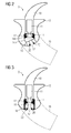
- a deflection of the propagation direction of the sound generated by the receiver 11 can be realized by means of a spherical alignment element 18.
- a spherical alignment element 18 This in FIG. 3 illustrated embodiment of the receiver device 9 is particularly for less curved Ear canals (for more curved ear canals, see third embodiment, FIG. 5 ).
- the spherical alignment element 18 is pivotally mounted in the adapter 14, so that a deflection of the direction of the exiting sound can be designed arbitrarily.
- the spherical alignment member 18 is in a rotated position in FIG FIG. 4 shown.
- the sound generated by the receiver 11 is guided through a continuous opening 19 of the spherical alignment element 18, which here forms the sound outlet opening 17.
- the spherical alignment member 18 is oriented so that the sound is conducted directly to the eardrum.
- the spherical alignment element 18 is designed so that it takes over the cerumen protection function: the cerumen protection element 20 is integrated into the spherical alignment element 18.
- the spherical alignment member 18 is also used in addition to the curved adapter 14. It makes sense to use this embodiment in a highly curved ear canal 16. It is important to remember that the curvature of the adapter 14 can not be arbitrarily designed. This results in difficulties when inserting a very strongly curved adapter 14 in the earmold 13. In the receiver device 9 of FIG. 5 the deflection of the sound direction can be realized on the one hand by the adapter 14 and on the other hand by the spherical alignment element 18, so that an overall optimal alignment of the sound to the ear canal 16 is achieved.
Landscapes
- Engineering & Computer Science (AREA)
- Physics & Mathematics (AREA)
- Acoustics & Sound (AREA)
- Signal Processing (AREA)
- Health & Medical Sciences (AREA)
- General Health & Medical Sciences (AREA)
- Neurosurgery (AREA)
- Otolaryngology (AREA)
- Manufacturing & Machinery (AREA)
- Headphones And Earphones (AREA)
- Circuit For Audible Band Transducer (AREA)
- Stereophonic Arrangements (AREA)
Abstract
Description
- Die vorliegende Erfindung betrifft eine Hörereinrichtung für eine Hörvorrichtung mit einem Ohrstück zum Fixieren der Hörereinrichtung in einem Gehörgang, einem Hörer, der eine bevorzugte Schallaustrittsrichtung besitzt und einem Adapter zum Befestigen des Hörers in dem Ohrstück, wobei ein Schall des Hörers durch den Adapter geleitet wird. Unter dem Begriff Hörvorrichtung wird hier insbesondere ein Hörgerät verstanden. Darüber hinaus fallen unter den Begriff aber auch andere tragbare akustische Geräte wie Headsets, Kopfhörer und dergleichen.
- Hörgeräte sind tragbare Hörvorrichtungen, die zur Versorgung von Schwerhörenden dienen. Um den zahlreichen individuellen Bedürfnissen entgegenzukommen, werden unterschiedliche Bauformen von Hörgeräten wie Hinter-dem-Ohr-Hörgeräte (HdO), Hörgerät mit externem Hörer (RIC: receiver in the canal) und In-dem-Ohr-Hörgeräte (IdO), z.B. auch Concha-Hörgeräte oder Kanal-Hörgeräte (ITE, CIC), bereitgestellt. Die beispielhaft aufgeführten Hörgeräte werden am Außenohr oder im Gehörgang getragen. Darüber hinaus stehen auf dem Markt aber auch Knochenleitungshörhilfen, implantierbare oder vibrotaktile Hörhilfen zur Verfügung. Dabei erfolgt die Stimulation des geschädigten Gehörs entweder mechanisch oder elektrisch.
- Hörgeräte besitzen prinzipiell als wesentliche Komponenten einen Eingangswandler, einen Verstärker und einen Ausgangswandler. Der Eingangswandler ist in der Regel ein Schallempfänger, z. B. ein Mikrofon, und/oder ein elektromagnetischer Empfänger, z. B. eine Induktionsspule. Der Ausgangswandler ist meist als elektroakustischer Wandler, z. B. Miniaturlautsprecher, oder als elektromechanischer Wandler, z. B. Knochenleitungshörer, realisiert. Der Verstärker ist üblicherweise in eine Signalverarbeitungseinheit integriert. Dieser prinzipielle Aufbau ist in
FIG 1 am Beispiel eines Hinter-dem-Ohr-Hörgeräts dargestellt. In ein Hörgerätegehäuse 1 zum Tragen hinter dem Ohr sind ein oder mehrere Mikrofone 2 zur Aufnahme des Schalls aus der Umgebung eingebaut. Eine Signalverarbeitungseinheit 3, die ebenfalls in das Hörgerätegehäuse 1 integriert ist, verarbeitet die Mikrofonsignale und verstärkt sie. Das Ausgangssignal der Signalverarbeitungseinheit 3 wird an einen Lautsprecher bzw. Hörer 4 übertragen, der ein akustisches Signal ausgibt. Der Schall wird gegebenenfalls über einen Schallschlauch, der mit einer Otoplastik im Gehörgang fixiert ist, zum Trommelfell des Geräteträgers übertragen. Die Stromversorgung des Hörgeräts und insbesondere die der Signalverarbeitungseinheit 3 erfolgt durch eine ebenfalls ins Hörgerätegehäuse 1 integrierte Batterie 5. - Hörgeräte mit externen Hörern werden im Wesentlichen derart gestaltet, dass eine Hörereinheit einschließlich eines Hörers in einer individuell geformten Otoplastik austauschbar gelagert ist. Hierzu benötigt man einen Adapter, der ein aus der Hörereinheit herausragendes Kopfelement aufnimmt und somit die Hörereinheit in der Otoplastik befestigt. Somit entsteht ein langer starrer Aufbau, der zusätzlich durch ein Cerumenschutzelement, das optional in das Hörgerät eingebaut werden kann, verlängert wird.
- Der typische menschliche Gehörgang weist einen mal mehr, mal weniger stark gekrümmten Eingangsbereich auf. Anzuraten ist deshalb die Verwendung kleiner und kurzer Hörer. Höhere Verstärkungen erfordern allerdings lange bzw. große Hörer, die insgesamt einen starren langen Aufbau der Otoplastik zur Folge haben. Somit besteht ein Problem darin, dass durch den langen Aufbau der Hörereinheit keine optimale Anpassung an den Gehörgang erzielt werden kann. Bei einem zu stark gekrümmten Gehörgang wird oftmals auf eine individuell geformte Otoplastik mit einem externen Hörer verzichtet. Des Weiteren ergeben sich Schwierigkeiten, wenn der von dem Hörer erzeugte Schall in einem stark gekrümmten Gehörgang auf eine Wand des Gehörgangs zu ausgegeben wird. Es besteht dabei der Nachteil, dass der Schall von der Wand zu sehr gedämpft wird. Die Aufgabe der vorliegenden Erfindung besteht somit darin, eine Hörereinrichtung für eine Hörvorrichtung bereitzustellen, bei der eine zuverlässige Anpassung an einen Gehörgang hinsichtlich des Schallauslasses ermöglicht wird.
- Die Druckschrift
DE 10 2004 009 268 B3 offenbart einen Ohreinsatz für ein Hörersystem. Der Ohreinsatz umfasst einen Formkörper und einen Hörer, der in dem Formkörper entnehmbar angeordnet ist. Dabei ist ein Schallaustritt zwischen dem Hörer und der Seite des Formkörpers ausgebildet, die in dem Zustand, in welchem der Ohreinsatz in einen Gehörgang eingesetzt ist, dem Trommelfell zugewandt ist. Ferner ist der Schallaustritt in einer Kapsel ausgebildet und weist die Form eines Exponentialhorns auf. - Die Druckschrift
DE 1 99 43 809 A1 offenbart ein Hörgerät mit einer Otoplastik, die eine Gehäuseschale des Hörgeräts bildet und nach einem Abdruck des äußeren Gehörgangs des Benutzers hergestellt ist. Die Otoplastik enthält einen Hörer, welcher ein elektrisches Signal in eine Schallwelle umsetzt. Bei diesem bekannten Hörgerät ist ein Ansatzkörper vorgesehen, welcher am trommelfellseitigen inneren Ende der Otoplastik angeordnet ist. Der Ansatzkörper ragt dabei in einen Raum zwischen der Otoplastik und dem Trommelfell des Gehörgangs hinein. Der Ansatzkörper ist durch ein Anschlussrohr gehalten, welches am inneren Ende der Otoplastik eingesetzt ist und in einen Schallkanal des Ansatzkörpers ragt. - Diese Aufgabe wird erfindungsgemäß gelöst durch eine Hörereinrichtung für eine Hörvorrichtung mit einem Ohrstück zum Fixieren der Hörereinrichtung in einem Gehörgang, einem Hörer, der eine bevorzugte Schallaustrittsrichtung besitzt und einem Adapter zum Befestigen des Hörers in dem Ohrstück, wobei ein Schall des Hörers durch den Adapter geleitet wird, und wobei der Adapter derart gestaltet ist, dass er den Schall von der bevorzugten Schallaustrittsrichtung in eine davon ausweichende Richtung umlenkt.
- In vorteilhafter Weise wird somit nicht nur eine Anpassung der Hörereinrichtung an den Gehörgang hinsichtlich der Form erreicht, sondern auch eine bessere Anpassung hinsichtlich des Schalleintrittswinkels in den Gehörgang. Die Schallaustrittsrichtung des Hörers kann nämlich derart umgelenkt werden, dass der Schall zumindest annähernd in Erstreckungsrichtung des Gehörgangs von der Hörereinrichtung ausgegeben wird. Somit werden Reflexionen des Schalls an den Wänden des Gehörgangs größtenteils vermieden und eine hindernisfreie Ausbreitung des Schalls in Richtung des Trommelfells ermöglicht.
- Vorzugsweise ist der Adapter gekrümmt ausgebildet, um die bevorzugte Schallaustrittsrichtung in die davon abweichende Richtung umzulenken. Eine Krümmung des Adapters lässt sich aufwandsarm und kostengünstig gestalten. Ein weiterer Vorteil der Ausführungsform besteht darin, durch die gekrümmte Form des Adapters das von dem Hörer ausgegebene Schallsignal besonders exakt in Richtung des Gehörgangs auszusenden.
- Gemäß einer weiteren günstigen Ausgestaltung der Hörereinrichtung kann der Adapter balgartig ausgebildet sein. Eine balgartige Ausgestaltung des Adapters ermöglicht es, die Krümmung des Adapters variabel einzustellen und somit die Anpassung weiterhin zu verbessern. Die Krümmung des Adapters kann somit individuell, abhängig von der Form des Gehörgangs gestaltet werden.
- In einer sehr bevorzugten Ausführungsform der Hörereinrichtung ist der Adapter gekrümmt oder balgartig ausgebildet, wobei zusätzlich ein kugelförmiges Ausrichtelement, das eine durchgängige Öffnung zum Durchlassen des Schalls aufweist, in dem Adapter schwenkbar gelagert ist, wobei die durchgängige Öffnung des kugelförmigen Ausrichtelements eine Schallaustrittsöffnung des Ohrstücks bildet, und wobei das kugelförmige Ausrichtelement ausgelegt ist, den Schall von der bevorzugten Schallaustrittsrichtung in die abweichende Richtung umzulenken. Somit kann das Ohrstück selbst bei sehr stark gekrümmtem Gehörgang individuell geformt werden. Weil ein Adapter mit einer zu großen Krümmung in eine Otoplastik sehr schwer einsteckbar ist, kann z.B. bei einer zu erreichenden Krümmung von 30° ein um 15° gekrümmter Adapter eingesetzt werden, wobei die restlichen 15° durch das kugelförmige Ausrichtelement übernommen werden.
- Das kugelförmige Ausrichtelement, das die durchgängige Öffnung zum Durchlassen des Schalls aufweist, kann alternativ zu der Krümmung oder zu der balgartigen Form des Adapters in dem Adapter schwenkbar gelagert sein, wobei die durchgängige Öffnung des kugelförmigen Ausrichtelements weiterhin die Schallaustrittsöffnung des Ohrstücks bildet und wobei das kugelförmige Ausrichtelement ausgelegt ist, den Schall von der bevorzugten Schallaustrittsrichtung in die abweichende Richtung umzulenken. Diese Ausführungsform der Hörereinrichtung ist besonders für einen weniger gekrümmten Gehörgang geeignet. Somit kann die Schallaustrittsrichtung so eingestellt werden, dass der Schall von dem Gehörgang nicht reflektiert und nicht gedämpft wird.
- Bei einer weiteren besonders vorteilhaften Ausführungsform der Hörereinrichtung ist ein Cerumenschutzelement in den Adapter oder in das kugelförmige Ausrichtelement integriert. Durch das Cerumenschutzelement wird die Schallaustrittsöffnung der Hörereinrichtung und insbesondere der Hörer vor Cerumen geschützt.
- Die vorliegende Erfindung wird anhand der beigefügten Zeichnungen näher erläutert, in denen zeigen:
- FIG 1
- einen schematischen Aufbau eines Hinter-dem-Ohr- Hörgeräts gemäß dem Stand der Technik;
- FIG 2
- eine erfindungsgemäße Hörereinrichtung gemäß einem ersten Ausführungsbeispiel;
- FIG 3
- eine erfindungsgemäße Hörereinrichtung gemäß einem zweiten Ausführungsbeispiel;
- FIG 4
- die erfindungsgemäße Hörereinrichtung gemäß dem zweiten Ausführungsbeispiel mit verändertem Schallaustrittswinkel;
- FIG 5
- eine erfindungsgemäße Hörereinrichtung gemäß einem dritten Ausführungsbeispiel.
- Entsprechend einem ersten in
FIG 2 wiedergegebenen Ausführungsbeispiel umfasst eine erfindungsgemäße Hörereinrichtung 9 eine Otoplastik 13, in der eine Hörereinheit einschließlich eines Hörergehäuses 10 und eines Hörers 11 austauschbar gelagert ist. An Stelle der Otoplastik kann auch ein anderes Ohrstück, z.B. ein so genannter "ear tip", der nicht individuell geformt ist, eingesetzt werden. Die Otoplastik 13 kann in einen menschlichen Gehörgang eingesetzt werden. Der Hörer 11 weist einen kegelstumpfförmigen Schallausgang 12 auf, der aus dem Hörergehäuse 10 herausragt und in einem Adapter 14 aufgenommen ist und in einer ringförmigen Einschneidung gehalten wird. Dabei hat der Adapter 14 die Aufgabe, die Hörereinheit in der Otoplastik 13 zu befestigen. - Der Adapter 14 weist im Wesentlichen einen Befestigungsteil 14a, in dem der Schallausgang 12 des Hörers 11 aufgenommen ist, sowie einen Schallausgabeteil 14b auf, der eine Austrittsrichtung des durch den Adapter 14 zu übertragenden Schalls definiert. Üblicherweise wird der Adapter 14 so gestaltet, dass eine durch den Schallausgang 12 des Hörers 11 festgelegte bevorzugte Schallaustrittsrichtung durch den Adapter 14 nicht beeinflusst wird. Weil sich somit eine nicht optimale Einkopplung des ausgegebenen Schalls in den Gehörgang 16 beziehungsweise Ohrkanal ergibt, besteht vorliegend der Grundgedanke darin, den Adapter 14 so auszugestalten, dass die von dem Schallausgang 12 des Hörers 11 ursprünglich definierte bevorzugte Schallaustrittsrichtung durch den Adapter 14 umgelenkt wird. Hierzu ist der Schallausgabeteil 14b des Adapters 14 gewinkelt zu dem Befestigungsteil 14a ausgebildet, so dass der Adapter 14 eine Krümmung aufweist.
- Wie in
FIG 2 dargestellt, ermöglicht die Krümmung des Adapters 14 eine bessere Ausrichtung des von dem Hörer 11 erzeugten Schalls hinsichtlich des Gehörgangs 16. Erkennbar ist, dass der Schall nicht wie üblicherweise an einem Rand des Gehörgangs 16, sondern an den Gehörgang 16 derart ausgegeben wird, dass sich der Schall direkt zu einem Trommelfell ausbreiten kann. Dabei werden Reflektionen des Schalls an der Wand des Gehörgangs 16 vermieden. - Zum Schutz des Hörers, insbesondere des Schallausgangs 12, wird weiterhin in der Otoplastik 13 zwischen dem Adapter 14 (genauer dem Schallausgabeteil 14b) und einer Schallaustrittsöffnung 17 eine Cerumenschutzeinrichtung 15 mit einem darin integrierten Cerumenschutzelement 20 eingesetzt. Diese Cerumenschutzeinrichtung 15 verlängert im Wesentlichen den Aufbau der Hörereinrichtung 9, so dass bei der herkömmlichen Lösung mit gerade gestaltetem Adapter der Einsatz von der Cerumenschutzeinrichtung problematisch sein kann. Wie in
FIG 2 zu erkennen ist, ist durch die geschickte Krümmung des Adapters 14 ein problemloser Einsatz der Cerumenschutzeinrichtung 15 ermöglicht. Des Weiteren kann zugunsten höherer Verstärkungen des Schalls ein größerer Hörer 11 in die Hörereinrichtung 9 eingebaut werden. - Gemäß einem zweiten Ausführungsbeispiel der erfindungsgemäßen Hörereinrichtung 9 kann eine Umlenkung der Ausbreitungsrichtung des von dem Hörer 11 erzeugten Schalls mittels eines kugelförmigen Ausrichtelements 18 realisiert werden. Diese in
FIG 3 dargestellte Ausführungsform der Hörereinrichtung 9 ist besonders für weniger gekrümmte Gehörgänge geeignet (für stärker gekrümmte Gehörgänge vgl. drittes Ausführungsbeispiel,FIG 5 ). Das kugelförmige Ausrichtelement 18 ist in dem Adapter 14 schwenkbar gelagert, so dass eine Umlenkung der Richtung des austretenden Schalls beliebig gestaltet werden kann. Das kugelförmige Ausrichtelement 18 ist in einer gedrehten Stellung inFIG 4 gezeigt. Der von dem Hörer 11 erzeugte Schall wird durch eine durchgängige Öffnung 19 des kugelförmigen Ausrichtelements 18, die hier die Schallaustrittsöffnung 17 bildet, geleitet. Das kugelförmige Ausrichtelement 18 ist so ausgerichtet, dass der Schall direkt an das Trommelfell geleitet wird. Darüber hinaus ist das kugelförmige Ausrichtelement 18 so ausgebildet, dass es die Cerumenschutzfunktion übernimmt: Das Cerumenschutzelement 20 ist in das kugelförmige Ausrichtelement 18 integriert. - Gemäß einem in
FIG 5 dargestellten dritten Ausführungsbeispiel der Hörereinrichtung 9 wird neben dem gekrümmten Adapter 14 ebenfalls das kugelförmige Ausrichtelement 18 eingesetzt. Es bietet sich an, diese Ausführungsform bei einem stark gekrümmten Gehörgang 16 zu verwenden. Zu denken ist hierbei daran, dass die Krümmung des Adapters 14 nicht beliebig gestaltet werden kann. Es ergeben sich nämlich Schwierigkeiten beim Einsetzten eines sehr stark gekrümmten Adapters 14 in die Otoplastik 13. Bei der Hörereinrichtung 9 vonFIG 5 kann die Umlenkung der Schallrichtung einerseits durch den Adapter 14 und andererseits durch das kugelförmige Ausrichtelement 18 realisiert sein, so dass insgesamt eine optimale Ausrichtung des Schalls an den Ohrkanal 16 erreicht wird.
Claims (6)
- Hörereinrichtung (9) für eine Hörvorrichtung mit- einem Ohrstück (13) zum Fixieren der Hörereinrichtung (9) in einem Gehörgang (16),- einem Hörer (11), der eine bevorzugte Schallaustrittsrichtung besitzt,- einem Adapter (14) zum Befestigen des Hörers (11) in dem Ohrstück (13), wobei ein Schall des Hörers (11) durch den Adapter (14) geleitet wird,dadurch gekennzeichnet, dass- der Adapter (14) derart gestaltet ist, dass er den Schall von der bevorzugten Schallaustrittsrichtung in eine davon abweichende Richtung umlenkt.
- Hörereinrichtung nach Anspruch 1, wobei der Adapter (14) gekrümmt ausgebildet ist, um den Schall von der bevorzugten Schallaustrittsrichtung in die davon abweichende Richtung umzulenken.
- Hörereinrichtung nach Anspruch 1 oder 2, wobei der Adapter (14) balgartig ausgebildet ist.
- Hörereinrichtung nach Anspruch 1, wobei der Adapter (14) gekrümmt oder balgartig ausgebildet ist, und ein kugelförmiges Ausrichtelement (18), das eine durchgängige Öffnung (19) zum Durchlassen des Schalls aufweist, in dem Adapter (14) schwenkbar gelagert ist, wobei die durchgängige Öffnung (19) des kugelförmigen Ausrichtelements (18) eine Schallaustrittsöffnung (17) des Ohrstücks (13) bildet, und wobei das kugelförmige Ausrichtelement (18) ausgelegt ist, den Schall von der bevorzugten Schallaustrittsrichtung in die abweichende Richtung umzulenken.
- Hörereinrichtung nach Anspruch 1, wobei ein kugelförmiges Ausrichtelement (18), das eine durchgängige Öffnung (19) zum Durchlassen des Schalls aufweist, in dem Adapter (14) schwenkbar gelagert ist, wobei die durchgängige Öffnung (19) des kugelförmigen Ausrichtelements (18) eine Schallaustrittsöffnung (17) des Ohrstücks (13) bildet, und wobei das kugelförmige Ausrichtelement (18) ausgelegt ist, den Schall von der bevorzugten Schallaustrittsrichtung in die davon abweichende Richtung umzulenken.
- Hörereinrichtung nach einem der vorhergehenden Ansprüche, wobei ein Cerumenschutzelement (20) in den Adapter (14) oder in das kugelförmige Ausrichtelement (18) integriert ist.
Applications Claiming Priority (1)
| Application Number | Priority Date | Filing Date | Title |
|---|---|---|---|
| DE102007036567A DE102007036567A1 (de) | 2007-08-03 | 2007-08-03 | Hörereinrichtung mit beeinflussbarer Schallaustrittsrichtung |
Publications (2)
| Publication Number | Publication Date |
|---|---|
| EP2023665A1 true EP2023665A1 (de) | 2009-02-11 |
| EP2023665B1 EP2023665B1 (de) | 2009-09-02 |
Family
ID=39929928
Family Applications (1)
| Application Number | Title | Priority Date | Filing Date |
|---|---|---|---|
| EP08104695A Not-in-force EP2023665B1 (de) | 2007-08-03 | 2008-07-10 | Hörereinrichtung mit beeinflussbarer Schallaustrittsrichtung |
Country Status (5)
| Country | Link |
|---|---|
| US (1) | US8098866B2 (de) |
| EP (1) | EP2023665B1 (de) |
| AT (1) | ATE442010T1 (de) |
| DE (2) | DE102007036567A1 (de) |
| DK (1) | DK2023665T3 (de) |
Cited By (1)
| Publication number | Priority date | Publication date | Assignee | Title |
|---|---|---|---|---|
| EP3739905B1 (de) | 2019-05-13 | 2024-11-27 | Sonova AG | Ohrstück mit nicht in einer achse angeordnetem elektronikgehäuse und hörer im gehörgang |
Families Citing this family (8)
| Publication number | Priority date | Publication date | Assignee | Title |
|---|---|---|---|---|
| US9386383B2 (en) | 2014-04-10 | 2016-07-05 | Gn Resound A/S | Hearing aid receiver and a hearing aid comprising such a receiver |
| US9392385B2 (en) | 2014-04-10 | 2016-07-12 | Gn Resound A/S | Hearing aid |
| DK201470199A1 (en) * | 2014-04-10 | 2015-10-26 | Gn Resound As | A hearing aid with replacable receiver |
| DK201470201A1 (en) * | 2014-04-10 | 2015-10-26 | Gn Resound As | Hearing aid with a receiver |
| DK201470202A1 (en) * | 2014-04-10 | 2015-10-26 | Gn Resound As | A hearing aid with receiver |
| DK201470200A1 (en) * | 2014-04-10 | 2015-10-26 | Gn Resound As | A hearing aid receiver with a filter holder and a hearing aid comprising such a receiver |
| US9578430B2 (en) | 2014-04-10 | 2017-02-21 | Gn Hearing A/S | Hearing aid |
| DE102017207528A1 (de) * | 2017-05-04 | 2018-11-08 | Sivantos Pte. Ltd. | Modul zum Einbau in ein Hörhilfegerät |
Citations (5)
| Publication number | Priority date | Publication date | Assignee | Title |
|---|---|---|---|---|
| US3983336A (en) * | 1974-10-15 | 1976-09-28 | Hooshang Malek | Directional self containing ear mounted hearing aid |
| CH648172A5 (en) | 1979-06-12 | 1985-02-28 | Minisonic Ag | Hearing-aid to be worn in the ear |
| WO1996021334A1 (en) | 1994-12-29 | 1996-07-11 | Decibel Instruments, Inc. | Articulated hearing device |
| US5960095A (en) | 1998-06-11 | 1999-09-28 | Sun Technique Electric Co., Ltd. | Loudspeaker assembly with adjustable directivity |
| WO2000008893A1 (en) * | 1998-07-24 | 2000-02-17 | Meditron As | Head phone |
Family Cites Families (4)
| Publication number | Priority date | Publication date | Assignee | Title |
|---|---|---|---|---|
| US6212283B1 (en) * | 1997-09-03 | 2001-04-03 | Decibel Instruments, Inc. | Articulation assembly for intracanal hearing devices |
| DE19943809A1 (de) * | 1999-09-14 | 2001-03-15 | Acousticon Hoersyteme Gmbh | Hörgerät |
| DE102004009268B3 (de) | 2004-02-26 | 2005-10-20 | Siemens Audiologische Technik | Ohreinsatz für ein Hörsystem |
| US7706557B2 (en) * | 2006-03-13 | 2010-04-27 | Siemens Hearing Instruments Inc. | Chambers for a hearing instrument shell |
-
2007
- 2007-08-03 DE DE102007036567A patent/DE102007036567A1/de not_active Ceased
-
2008
- 2008-07-10 AT AT08104695T patent/ATE442010T1/de active
- 2008-07-10 DK DK08104695T patent/DK2023665T3/da active
- 2008-07-10 DE DE502008000096T patent/DE502008000096D1/de active Active
- 2008-07-10 EP EP08104695A patent/EP2023665B1/de not_active Not-in-force
- 2008-07-31 US US12/221,433 patent/US8098866B2/en not_active Expired - Fee Related
Patent Citations (5)
| Publication number | Priority date | Publication date | Assignee | Title |
|---|---|---|---|---|
| US3983336A (en) * | 1974-10-15 | 1976-09-28 | Hooshang Malek | Directional self containing ear mounted hearing aid |
| CH648172A5 (en) | 1979-06-12 | 1985-02-28 | Minisonic Ag | Hearing-aid to be worn in the ear |
| WO1996021334A1 (en) | 1994-12-29 | 1996-07-11 | Decibel Instruments, Inc. | Articulated hearing device |
| US5960095A (en) | 1998-06-11 | 1999-09-28 | Sun Technique Electric Co., Ltd. | Loudspeaker assembly with adjustable directivity |
| WO2000008893A1 (en) * | 1998-07-24 | 2000-02-17 | Meditron As | Head phone |
Cited By (1)
| Publication number | Priority date | Publication date | Assignee | Title |
|---|---|---|---|---|
| EP3739905B1 (de) | 2019-05-13 | 2024-11-27 | Sonova AG | Ohrstück mit nicht in einer achse angeordnetem elektronikgehäuse und hörer im gehörgang |
Also Published As
| Publication number | Publication date |
|---|---|
| ATE442010T1 (de) | 2009-09-15 |
| US20090034770A1 (en) | 2009-02-05 |
| DE102007036567A1 (de) | 2009-02-05 |
| US8098866B2 (en) | 2012-01-17 |
| DE502008000096D1 (de) | 2009-10-15 |
| EP2023665B1 (de) | 2009-09-02 |
| DK2023665T3 (da) | 2009-12-21 |
Similar Documents
| Publication | Publication Date | Title |
|---|---|---|
| EP2023665B1 (de) | Hörereinrichtung mit beeinflussbarer Schallaustrittsrichtung | |
| DE102006024411B4 (de) | Verfahren zum Erzeugen eines Schallsignals oder zum Übertragen von Energie in einem Gehörgang und entsprechende Hörvorrichtung | |
| EP2534855B1 (de) | Hinter-dem-ohr-hörgerät mit steckverbinder | |
| EP2026605A1 (de) | Hörereinrichtung mit elastisch gelagertem Hörer | |
| EP2180724A1 (de) | Ohrstück mit Stegen | |
| EP3491846B1 (de) | Hörhilfegerät und hörhilfevorrichtung | |
| EP2654322B1 (de) | Hörinstrument mit Schallschlauch-Steckverbindung | |
| EP2200343A1 (de) | Im-Ohr-tragbares Hörhilfegerät mit einem Richtmikrofon | |
| EP1993323B1 (de) | Ohrstück für eine Hörvorrichtung mit Bajonettverschluss | |
| EP2003930B1 (de) | Hörgerät mit am Gehäuserahmen befestigtem Anschlussstück | |
| EP2040488A2 (de) | Werkzeug zum Einsetzen eines Hörers einer Hörvorrichtung in einen Gehörgang | |
| EP2007172B1 (de) | Schallausgangsröhrchen mit 2-Komponenten-Aufbau | |
| EP2713799B1 (de) | Hörgeräteeinheit mit einem ohrschmuck und einem hörgerät | |
| EP2393310B1 (de) | Tief-Ohrkanal-Hörinstrument | |
| EP2574083A2 (de) | IDO-Hörinstrument mit Programmierbuchse | |
| EP2180725B1 (de) | Hörereinrichtung mit schwingungsentkoppeltem Hörer | |
| DE102008052682B4 (de) | Hörereinrichtung mit beweglichem Hörer | |
| EP1998593A1 (de) | Ohrstück für eine Hörvorrichtung mit Sicherungsring | |
| DE102014200917A1 (de) | HdO-Hörinstrument mit Gehäuse und Schallschlauch | |
| EP2552129B1 (de) | Hörvorrichtung mit speziellem Schallkanal | |
| EP2373065B1 (de) | Hörvorrichtung und Verfahren zum Erzeugen einer omnidirektionalen Richtcharakteristik | |
| EP2217009B1 (de) | Hörvorrichtung mit Tragehakenerkennung | |
| EP3188511A1 (de) | Hörgerät | |
| DE102006052436B4 (de) | Hörgerät | |
| DE102010042150A1 (de) | Ohrstück für ein Hörinstrument und Hörinstrument mit Ohrstück |
Legal Events
| Date | Code | Title | Description |
|---|---|---|---|
| PUAI | Public reference made under article 153(3) epc to a published international application that has entered the european phase |
Free format text: ORIGINAL CODE: 0009012 |
|
| AK | Designated contracting states |
Kind code of ref document: A1 Designated state(s): AT BE BG CH CY CZ DE DK EE ES FI FR GB GR HR HU IE IS IT LI LT LU LV MC MT NL NO PL PT RO SE SI SK TR |
|
| AX | Request for extension of the european patent |
Extension state: AL BA MK RS |
|
| GRAP | Despatch of communication of intention to grant a patent |
Free format text: ORIGINAL CODE: EPIDOSNIGR1 |
|
| 17P | Request for examination filed |
Effective date: 20090223 |
|
| GRAS | Grant fee paid |
Free format text: ORIGINAL CODE: EPIDOSNIGR3 |
|
| GRAA | (expected) grant |
Free format text: ORIGINAL CODE: 0009210 |
|
| AK | Designated contracting states |
Kind code of ref document: B1 Designated state(s): AT BE BG CH CY CZ DE DK EE ES FI FR GB GR HR HU IE IS IT LI LT LU LV MC MT NL NO PL PT RO SE SI SK TR |
|
| REG | Reference to a national code |
Ref country code: CH Ref legal event code: EP |
|
| REG | Reference to a national code |
Ref country code: IE Ref legal event code: FG4D Free format text: LANGUAGE OF EP DOCUMENT: GERMAN |
|
| AKX | Designation fees paid |
Designated state(s): AT BE BG CH CY CZ DE DK EE ES FI FR GB GR HR HU IE IS IT LI LT LU LV MC MT NL NO PL PT RO SE SI SK TR |
|
| REF | Corresponds to: |
Ref document number: 502008000096 Country of ref document: DE Date of ref document: 20091015 Kind code of ref document: P |
|
| REG | Reference to a national code |
Ref country code: CH Ref legal event code: NV Representative=s name: SIEMENS SCHWEIZ AG |
|
| REG | Reference to a national code |
Ref country code: DK Ref legal event code: T3 |
|
| PG25 | Lapsed in a contracting state [announced via postgrant information from national office to epo] |
Ref country code: NO Free format text: LAPSE BECAUSE OF FAILURE TO SUBMIT A TRANSLATION OF THE DESCRIPTION OR TO PAY THE FEE WITHIN THE PRESCRIBED TIME-LIMIT Effective date: 20091202 Ref country code: LT Free format text: LAPSE BECAUSE OF FAILURE TO SUBMIT A TRANSLATION OF THE DESCRIPTION OR TO PAY THE FEE WITHIN THE PRESCRIBED TIME-LIMIT Effective date: 20090902 Ref country code: SE Free format text: LAPSE BECAUSE OF FAILURE TO SUBMIT A TRANSLATION OF THE DESCRIPTION OR TO PAY THE FEE WITHIN THE PRESCRIBED TIME-LIMIT Effective date: 20090902 Ref country code: FI Free format text: LAPSE BECAUSE OF FAILURE TO SUBMIT A TRANSLATION OF THE DESCRIPTION OR TO PAY THE FEE WITHIN THE PRESCRIBED TIME-LIMIT Effective date: 20090902 |
|
| NLV1 | Nl: lapsed or annulled due to failure to fulfill the requirements of art. 29p and 29m of the patents act | ||
| LTIE | Lt: invalidation of european patent or patent extension |
Effective date: 20090902 |
|
| PG25 | Lapsed in a contracting state [announced via postgrant information from national office to epo] |
Ref country code: PL Free format text: LAPSE BECAUSE OF FAILURE TO SUBMIT A TRANSLATION OF THE DESCRIPTION OR TO PAY THE FEE WITHIN THE PRESCRIBED TIME-LIMIT Effective date: 20090902 Ref country code: NL Free format text: LAPSE BECAUSE OF FAILURE TO SUBMIT A TRANSLATION OF THE DESCRIPTION OR TO PAY THE FEE WITHIN THE PRESCRIBED TIME-LIMIT Effective date: 20090902 Ref country code: HR Free format text: LAPSE BECAUSE OF FAILURE TO SUBMIT A TRANSLATION OF THE DESCRIPTION OR TO PAY THE FEE WITHIN THE PRESCRIBED TIME-LIMIT Effective date: 20090902 Ref country code: SI Free format text: LAPSE BECAUSE OF FAILURE TO SUBMIT A TRANSLATION OF THE DESCRIPTION OR TO PAY THE FEE WITHIN THE PRESCRIBED TIME-LIMIT Effective date: 20090902 Ref country code: LV Free format text: LAPSE BECAUSE OF FAILURE TO SUBMIT A TRANSLATION OF THE DESCRIPTION OR TO PAY THE FEE WITHIN THE PRESCRIBED TIME-LIMIT Effective date: 20090902 |
|
| PG25 | Lapsed in a contracting state [announced via postgrant information from national office to epo] |
Ref country code: CY Free format text: LAPSE BECAUSE OF FAILURE TO SUBMIT A TRANSLATION OF THE DESCRIPTION OR TO PAY THE FEE WITHIN THE PRESCRIBED TIME-LIMIT Effective date: 20090902 |
|
| REG | Reference to a national code |
Ref country code: IE Ref legal event code: FD4D |
|
| PG25 | Lapsed in a contracting state [announced via postgrant information from national office to epo] |
Ref country code: IS Free format text: LAPSE BECAUSE OF FAILURE TO SUBMIT A TRANSLATION OF THE DESCRIPTION OR TO PAY THE FEE WITHIN THE PRESCRIBED TIME-LIMIT Effective date: 20100102 Ref country code: CZ Free format text: LAPSE BECAUSE OF FAILURE TO SUBMIT A TRANSLATION OF THE DESCRIPTION OR TO PAY THE FEE WITHIN THE PRESCRIBED TIME-LIMIT Effective date: 20090902 Ref country code: EE Free format text: LAPSE BECAUSE OF FAILURE TO SUBMIT A TRANSLATION OF THE DESCRIPTION OR TO PAY THE FEE WITHIN THE PRESCRIBED TIME-LIMIT Effective date: 20090902 Ref country code: ES Free format text: LAPSE BECAUSE OF FAILURE TO SUBMIT A TRANSLATION OF THE DESCRIPTION OR TO PAY THE FEE WITHIN THE PRESCRIBED TIME-LIMIT Effective date: 20091213 Ref country code: IE Free format text: LAPSE BECAUSE OF FAILURE TO SUBMIT A TRANSLATION OF THE DESCRIPTION OR TO PAY THE FEE WITHIN THE PRESCRIBED TIME-LIMIT Effective date: 20090902 Ref country code: RO Free format text: LAPSE BECAUSE OF FAILURE TO SUBMIT A TRANSLATION OF THE DESCRIPTION OR TO PAY THE FEE WITHIN THE PRESCRIBED TIME-LIMIT Effective date: 20090902 |
|
| PG25 | Lapsed in a contracting state [announced via postgrant information from national office to epo] |
Ref country code: SK Free format text: LAPSE BECAUSE OF FAILURE TO SUBMIT A TRANSLATION OF THE DESCRIPTION OR TO PAY THE FEE WITHIN THE PRESCRIBED TIME-LIMIT Effective date: 20090902 |
|
| PLBE | No opposition filed within time limit |
Free format text: ORIGINAL CODE: 0009261 |
|
| STAA | Information on the status of an ep patent application or granted ep patent |
Free format text: STATUS: NO OPPOSITION FILED WITHIN TIME LIMIT |
|
| 26N | No opposition filed |
Effective date: 20100603 |
|
| PG25 | Lapsed in a contracting state [announced via postgrant information from national office to epo] |
Ref country code: GR Free format text: LAPSE BECAUSE OF FAILURE TO SUBMIT A TRANSLATION OF THE DESCRIPTION OR TO PAY THE FEE WITHIN THE PRESCRIBED TIME-LIMIT Effective date: 20091203 |
|
| BERE | Be: lapsed |
Owner name: SIEMENS MEDICAL INSTRUMENTS PTE. LTD. Effective date: 20100731 |
|
| PG25 | Lapsed in a contracting state [announced via postgrant information from national office to epo] |
Ref country code: MC Free format text: LAPSE BECAUSE OF NON-PAYMENT OF DUE FEES Effective date: 20100731 |
|
| PG25 | Lapsed in a contracting state [announced via postgrant information from national office to epo] |
Ref country code: IT Free format text: LAPSE BECAUSE OF FAILURE TO SUBMIT A TRANSLATION OF THE DESCRIPTION OR TO PAY THE FEE WITHIN THE PRESCRIBED TIME-LIMIT Effective date: 20090902 |
|
| PG25 | Lapsed in a contracting state [announced via postgrant information from national office to epo] |
Ref country code: MT Free format text: LAPSE BECAUSE OF FAILURE TO SUBMIT A TRANSLATION OF THE DESCRIPTION OR TO PAY THE FEE WITHIN THE PRESCRIBED TIME-LIMIT Effective date: 20090902 |
|
| PG25 | Lapsed in a contracting state [announced via postgrant information from national office to epo] |
Ref country code: BE Free format text: LAPSE BECAUSE OF NON-PAYMENT OF DUE FEES Effective date: 20100731 |
|
| PGFP | Annual fee paid to national office [announced via postgrant information from national office to epo] |
Ref country code: DK Payment date: 20110720 Year of fee payment: 4 |
|
| PG25 | Lapsed in a contracting state [announced via postgrant information from national office to epo] |
Ref country code: BG Free format text: LAPSE BECAUSE OF FAILURE TO SUBMIT A TRANSLATION OF THE DESCRIPTION OR TO PAY THE FEE WITHIN THE PRESCRIBED TIME-LIMIT Effective date: 20090902 Ref country code: HU Free format text: LAPSE BECAUSE OF FAILURE TO SUBMIT A TRANSLATION OF THE DESCRIPTION OR TO PAY THE FEE WITHIN THE PRESCRIBED TIME-LIMIT Effective date: 20100303 Ref country code: PT Free format text: LAPSE BECAUSE OF FAILURE TO SUBMIT A TRANSLATION OF THE DESCRIPTION OR TO PAY THE FEE WITHIN THE PRESCRIBED TIME-LIMIT Effective date: 20100202 Ref country code: LU Free format text: LAPSE BECAUSE OF NON-PAYMENT OF DUE FEES Effective date: 20100710 |
|
| PG25 | Lapsed in a contracting state [announced via postgrant information from national office to epo] |
Ref country code: TR Free format text: LAPSE BECAUSE OF FAILURE TO SUBMIT A TRANSLATION OF THE DESCRIPTION OR TO PAY THE FEE WITHIN THE PRESCRIBED TIME-LIMIT Effective date: 20090902 |
|
| PGFP | Annual fee paid to national office [announced via postgrant information from national office to epo] |
Ref country code: GB Payment date: 20120709 Year of fee payment: 5 |
|
| PGFP | Annual fee paid to national office [announced via postgrant information from national office to epo] |
Ref country code: DE Payment date: 20120906 Year of fee payment: 5 Ref country code: FR Payment date: 20120802 Year of fee payment: 5 |
|
| PGFP | Annual fee paid to national office [announced via postgrant information from national office to epo] |
Ref country code: CH Payment date: 20121011 Year of fee payment: 5 |
|
| REG | Reference to a national code |
Ref country code: DK Ref legal event code: EBP Effective date: 20130731 |
|
| REG | Reference to a national code |
Ref country code: CH Ref legal event code: PL |
|
| GBPC | Gb: european patent ceased through non-payment of renewal fee |
Effective date: 20130710 |
|
| REG | Reference to a national code |
Ref country code: FR Ref legal event code: ST Effective date: 20140331 |
|
| PG25 | Lapsed in a contracting state [announced via postgrant information from national office to epo] |
Ref country code: LI Free format text: LAPSE BECAUSE OF NON-PAYMENT OF DUE FEES Effective date: 20130731 Ref country code: DE Free format text: LAPSE BECAUSE OF NON-PAYMENT OF DUE FEES Effective date: 20140201 Ref country code: CH Free format text: LAPSE BECAUSE OF NON-PAYMENT OF DUE FEES Effective date: 20130731 Ref country code: GB Free format text: LAPSE BECAUSE OF NON-PAYMENT OF DUE FEES Effective date: 20130710 |
|
| REG | Reference to a national code |
Ref country code: DE Ref legal event code: R119 Ref document number: 502008000096 Country of ref document: DE Effective date: 20140201 |
|
| PG25 | Lapsed in a contracting state [announced via postgrant information from national office to epo] |
Ref country code: FR Free format text: LAPSE BECAUSE OF NON-PAYMENT OF DUE FEES Effective date: 20130731 |
|
| REG | Reference to a national code |
Ref country code: AT Ref legal event code: MM01 Ref document number: 442010 Country of ref document: AT Kind code of ref document: T Effective date: 20130710 |
|
| PG25 | Lapsed in a contracting state [announced via postgrant information from national office to epo] |
Ref country code: DK Free format text: LAPSE BECAUSE OF NON-PAYMENT OF DUE FEES Effective date: 20130731 |
|
| PG25 | Lapsed in a contracting state [announced via postgrant information from national office to epo] |
Ref country code: AT Free format text: LAPSE BECAUSE OF NON-PAYMENT OF DUE FEES Effective date: 20130710 |