EP2022954A1 - Exhaust gas purifier of construction machine - Google Patents
Exhaust gas purifier of construction machine Download PDFInfo
- Publication number
- EP2022954A1 EP2022954A1 EP07744460A EP07744460A EP2022954A1 EP 2022954 A1 EP2022954 A1 EP 2022954A1 EP 07744460 A EP07744460 A EP 07744460A EP 07744460 A EP07744460 A EP 07744460A EP 2022954 A1 EP2022954 A1 EP 2022954A1
- Authority
- EP
- European Patent Office
- Prior art keywords
- remaining amount
- exhaust gas
- reducing agent
- engine
- agent solution
- Prior art date
- Legal status (The legal status is an assumption and is not a legal conclusion. Google has not performed a legal analysis and makes no representation as to the accuracy of the status listed.)
- Granted
Links
Images


Classifications
-
- F—MECHANICAL ENGINEERING; LIGHTING; HEATING; WEAPONS; BLASTING
- F01—MACHINES OR ENGINES IN GENERAL; ENGINE PLANTS IN GENERAL; STEAM ENGINES
- F01N—GAS-FLOW SILENCERS OR EXHAUST APPARATUS FOR MACHINES OR ENGINES IN GENERAL; GAS-FLOW SILENCERS OR EXHAUST APPARATUS FOR INTERNAL COMBUSTION ENGINES
- F01N3/00—Exhaust or silencing apparatus having means for purifying, rendering innocuous, or otherwise treating exhaust
- F01N3/08—Exhaust or silencing apparatus having means for purifying, rendering innocuous, or otherwise treating exhaust for rendering innocuous
-
- E—FIXED CONSTRUCTIONS
- E02—HYDRAULIC ENGINEERING; FOUNDATIONS; SOIL SHIFTING
- E02F—DREDGING; SOIL-SHIFTING
- E02F9/00—Component parts of dredgers or soil-shifting machines, not restricted to one of the kinds covered by groups E02F3/00 - E02F7/00
- E02F9/24—Safety devices, e.g. for preventing overload
-
- B—PERFORMING OPERATIONS; TRANSPORTING
- B01—PHYSICAL OR CHEMICAL PROCESSES OR APPARATUS IN GENERAL
- B01D—SEPARATION
- B01D53/00—Separation of gases or vapours; Recovering vapours of volatile solvents from gases; Chemical or biological purification of waste gases, e.g. engine exhaust gases, smoke, fumes, flue gases, aerosols
- B01D53/34—Chemical or biological purification of waste gases
- B01D53/74—General processes for purification of waste gases; Apparatus or devices specially adapted therefor
- B01D53/86—Catalytic processes
- B01D53/90—Injecting reactants
-
- B—PERFORMING OPERATIONS; TRANSPORTING
- B01—PHYSICAL OR CHEMICAL PROCESSES OR APPARATUS IN GENERAL
- B01D—SEPARATION
- B01D53/00—Separation of gases or vapours; Recovering vapours of volatile solvents from gases; Chemical or biological purification of waste gases, e.g. engine exhaust gases, smoke, fumes, flue gases, aerosols
- B01D53/34—Chemical or biological purification of waste gases
- B01D53/92—Chemical or biological purification of waste gases of engine exhaust gases
- B01D53/94—Chemical or biological purification of waste gases of engine exhaust gases by catalytic processes
- B01D53/9404—Removing only nitrogen compounds
- B01D53/9409—Nitrogen oxides
- B01D53/9431—Processes characterised by a specific device
-
- E—FIXED CONSTRUCTIONS
- E02—HYDRAULIC ENGINEERING; FOUNDATIONS; SOIL SHIFTING
- E02F—DREDGING; SOIL-SHIFTING
- E02F9/00—Component parts of dredgers or soil-shifting machines, not restricted to one of the kinds covered by groups E02F3/00 - E02F7/00
-
- E—FIXED CONSTRUCTIONS
- E02—HYDRAULIC ENGINEERING; FOUNDATIONS; SOIL SHIFTING
- E02F—DREDGING; SOIL-SHIFTING
- E02F9/00—Component parts of dredgers or soil-shifting machines, not restricted to one of the kinds covered by groups E02F3/00 - E02F7/00
- E02F9/20—Drives; Control devices
- E02F9/22—Hydraulic or pneumatic drives
- E02F9/2221—Control of flow rate; Load sensing arrangements
- E02F9/2232—Control of flow rate; Load sensing arrangements using one or more variable displacement pumps
- E02F9/2235—Control of flow rate; Load sensing arrangements using one or more variable displacement pumps including an electronic controller
-
- E—FIXED CONSTRUCTIONS
- E02—HYDRAULIC ENGINEERING; FOUNDATIONS; SOIL SHIFTING
- E02F—DREDGING; SOIL-SHIFTING
- E02F9/00—Component parts of dredgers or soil-shifting machines, not restricted to one of the kinds covered by groups E02F3/00 - E02F7/00
- E02F9/20—Drives; Control devices
- E02F9/22—Hydraulic or pneumatic drives
- E02F9/2246—Control of prime movers, e.g. depending on the hydraulic load of work tools
-
- E—FIXED CONSTRUCTIONS
- E02—HYDRAULIC ENGINEERING; FOUNDATIONS; SOIL SHIFTING
- E02F—DREDGING; SOIL-SHIFTING
- E02F9/00—Component parts of dredgers or soil-shifting machines, not restricted to one of the kinds covered by groups E02F3/00 - E02F7/00
- E02F9/20—Drives; Control devices
- E02F9/22—Hydraulic or pneumatic drives
- E02F9/226—Safety arrangements, e.g. hydraulic driven fans, preventing cavitation, leakage, overheating
-
- E—FIXED CONSTRUCTIONS
- E02—HYDRAULIC ENGINEERING; FOUNDATIONS; SOIL SHIFTING
- E02F—DREDGING; SOIL-SHIFTING
- E02F9/00—Component parts of dredgers or soil-shifting machines, not restricted to one of the kinds covered by groups E02F3/00 - E02F7/00
- E02F9/20—Drives; Control devices
- E02F9/22—Hydraulic or pneumatic drives
- E02F9/2278—Hydraulic circuits
- E02F9/2296—Systems with a variable displacement pump
-
- F—MECHANICAL ENGINEERING; LIGHTING; HEATING; WEAPONS; BLASTING
- F01—MACHINES OR ENGINES IN GENERAL; ENGINE PLANTS IN GENERAL; STEAM ENGINES
- F01N—GAS-FLOW SILENCERS OR EXHAUST APPARATUS FOR MACHINES OR ENGINES IN GENERAL; GAS-FLOW SILENCERS OR EXHAUST APPARATUS FOR INTERNAL COMBUSTION ENGINES
- F01N11/00—Monitoring or diagnostic devices for exhaust-gas treatment apparatus, e.g. for catalytic activity
-
- F—MECHANICAL ENGINEERING; LIGHTING; HEATING; WEAPONS; BLASTING
- F01—MACHINES OR ENGINES IN GENERAL; ENGINE PLANTS IN GENERAL; STEAM ENGINES
- F01N—GAS-FLOW SILENCERS OR EXHAUST APPARATUS FOR MACHINES OR ENGINES IN GENERAL; GAS-FLOW SILENCERS OR EXHAUST APPARATUS FOR INTERNAL COMBUSTION ENGINES
- F01N3/00—Exhaust or silencing apparatus having means for purifying, rendering innocuous, or otherwise treating exhaust
- F01N3/08—Exhaust or silencing apparatus having means for purifying, rendering innocuous, or otherwise treating exhaust for rendering innocuous
- F01N3/10—Exhaust or silencing apparatus having means for purifying, rendering innocuous, or otherwise treating exhaust for rendering innocuous by thermal or catalytic conversion of noxious components of exhaust
- F01N3/18—Exhaust or silencing apparatus having means for purifying, rendering innocuous, or otherwise treating exhaust for rendering innocuous by thermal or catalytic conversion of noxious components of exhaust characterised by methods of operation; Control
- F01N3/20—Exhaust or silencing apparatus having means for purifying, rendering innocuous, or otherwise treating exhaust for rendering innocuous by thermal or catalytic conversion of noxious components of exhaust characterised by methods of operation; Control specially adapted for catalytic conversion ; Methods of operation or control of catalytic converters
- F01N3/2066—Selective catalytic reduction [SCR]
- F01N3/208—Control of selective catalytic reduction [SCR], e.g. dosing of reducing agent
-
- F—MECHANICAL ENGINEERING; LIGHTING; HEATING; WEAPONS; BLASTING
- F01—MACHINES OR ENGINES IN GENERAL; ENGINE PLANTS IN GENERAL; STEAM ENGINES
- F01N—GAS-FLOW SILENCERS OR EXHAUST APPARATUS FOR MACHINES OR ENGINES IN GENERAL; GAS-FLOW SILENCERS OR EXHAUST APPARATUS FOR INTERNAL COMBUSTION ENGINES
- F01N9/00—Electrical control of exhaust gas treating apparatus
-
- F—MECHANICAL ENGINEERING; LIGHTING; HEATING; WEAPONS; BLASTING
- F02—COMBUSTION ENGINES; HOT-GAS OR COMBUSTION-PRODUCT ENGINE PLANTS
- F02D—CONTROLLING COMBUSTION ENGINES
- F02D29/00—Controlling engines, such controlling being peculiar to the devices driven thereby, the devices being other than parts or accessories essential to engine operation, e.g. controlling of engines by signals external thereto
- F02D29/04—Controlling engines, such controlling being peculiar to the devices driven thereby, the devices being other than parts or accessories essential to engine operation, e.g. controlling of engines by signals external thereto peculiar to engines driving pumps
-
- B—PERFORMING OPERATIONS; TRANSPORTING
- B01—PHYSICAL OR CHEMICAL PROCESSES OR APPARATUS IN GENERAL
- B01D—SEPARATION
- B01D2251/00—Reactants
- B01D2251/20—Reductants
- B01D2251/206—Ammonium compounds
- B01D2251/2062—Ammonia
-
- B—PERFORMING OPERATIONS; TRANSPORTING
- B01—PHYSICAL OR CHEMICAL PROCESSES OR APPARATUS IN GENERAL
- B01D—SEPARATION
- B01D2251/00—Reactants
- B01D2251/20—Reductants
- B01D2251/206—Ammonium compounds
- B01D2251/2067—Urea
-
- F—MECHANICAL ENGINEERING; LIGHTING; HEATING; WEAPONS; BLASTING
- F01—MACHINES OR ENGINES IN GENERAL; ENGINE PLANTS IN GENERAL; STEAM ENGINES
- F01N—GAS-FLOW SILENCERS OR EXHAUST APPARATUS FOR MACHINES OR ENGINES IN GENERAL; GAS-FLOW SILENCERS OR EXHAUST APPARATUS FOR INTERNAL COMBUSTION ENGINES
- F01N2550/00—Monitoring or diagnosing the deterioration of exhaust systems
- F01N2550/05—Systems for adding substances into exhaust
-
- F—MECHANICAL ENGINEERING; LIGHTING; HEATING; WEAPONS; BLASTING
- F01—MACHINES OR ENGINES IN GENERAL; ENGINE PLANTS IN GENERAL; STEAM ENGINES
- F01N—GAS-FLOW SILENCERS OR EXHAUST APPARATUS FOR MACHINES OR ENGINES IN GENERAL; GAS-FLOW SILENCERS OR EXHAUST APPARATUS FOR INTERNAL COMBUSTION ENGINES
- F01N2590/00—Exhaust or silencing apparatus adapted to particular use, e.g. for military applications, airplanes, submarines
- F01N2590/08—Exhaust or silencing apparatus adapted to particular use, e.g. for military applications, airplanes, submarines for heavy duty applications, e.g. trucks, buses, tractors, locomotives
-
- F—MECHANICAL ENGINEERING; LIGHTING; HEATING; WEAPONS; BLASTING
- F01—MACHINES OR ENGINES IN GENERAL; ENGINE PLANTS IN GENERAL; STEAM ENGINES
- F01N—GAS-FLOW SILENCERS OR EXHAUST APPARATUS FOR MACHINES OR ENGINES IN GENERAL; GAS-FLOW SILENCERS OR EXHAUST APPARATUS FOR INTERNAL COMBUSTION ENGINES
- F01N2610/00—Adding substances to exhaust gases
- F01N2610/02—Adding substances to exhaust gases the substance being ammonia or urea
-
- F—MECHANICAL ENGINEERING; LIGHTING; HEATING; WEAPONS; BLASTING
- F01—MACHINES OR ENGINES IN GENERAL; ENGINE PLANTS IN GENERAL; STEAM ENGINES
- F01N—GAS-FLOW SILENCERS OR EXHAUST APPARATUS FOR MACHINES OR ENGINES IN GENERAL; GAS-FLOW SILENCERS OR EXHAUST APPARATUS FOR INTERNAL COMBUSTION ENGINES
- F01N2610/00—Adding substances to exhaust gases
- F01N2610/14—Arrangements for the supply of substances, e.g. conduits
- F01N2610/1453—Sprayers or atomisers; Arrangement thereof in the exhaust apparatus
- F01N2610/146—Control thereof, e.g. control of injectors or injection valves
-
- F—MECHANICAL ENGINEERING; LIGHTING; HEATING; WEAPONS; BLASTING
- F01—MACHINES OR ENGINES IN GENERAL; ENGINE PLANTS IN GENERAL; STEAM ENGINES
- F01N—GAS-FLOW SILENCERS OR EXHAUST APPARATUS FOR MACHINES OR ENGINES IN GENERAL; GAS-FLOW SILENCERS OR EXHAUST APPARATUS FOR INTERNAL COMBUSTION ENGINES
- F01N2900/00—Details of electrical control or of the monitoring of the exhaust gas treating apparatus
- F01N2900/06—Parameters used for exhaust control or diagnosing
- F01N2900/18—Parameters used for exhaust control or diagnosing said parameters being related to the system for adding a substance into the exhaust
- F01N2900/1806—Properties of reducing agent or dosing system
- F01N2900/1814—Tank level
-
- Y—GENERAL TAGGING OF NEW TECHNOLOGICAL DEVELOPMENTS; GENERAL TAGGING OF CROSS-SECTIONAL TECHNOLOGIES SPANNING OVER SEVERAL SECTIONS OF THE IPC; TECHNICAL SUBJECTS COVERED BY FORMER USPC CROSS-REFERENCE ART COLLECTIONS [XRACs] AND DIGESTS
- Y02—TECHNOLOGIES OR APPLICATIONS FOR MITIGATION OR ADAPTATION AGAINST CLIMATE CHANGE
- Y02T—CLIMATE CHANGE MITIGATION TECHNOLOGIES RELATED TO TRANSPORTATION
- Y02T10/00—Road transport of goods or passengers
- Y02T10/10—Internal combustion engine [ICE] based vehicles
- Y02T10/12—Improving ICE efficiencies
-
- Y—GENERAL TAGGING OF NEW TECHNOLOGICAL DEVELOPMENTS; GENERAL TAGGING OF CROSS-SECTIONAL TECHNOLOGIES SPANNING OVER SEVERAL SECTIONS OF THE IPC; TECHNICAL SUBJECTS COVERED BY FORMER USPC CROSS-REFERENCE ART COLLECTIONS [XRACs] AND DIGESTS
- Y02—TECHNOLOGIES OR APPLICATIONS FOR MITIGATION OR ADAPTATION AGAINST CLIMATE CHANGE
- Y02T—CLIMATE CHANGE MITIGATION TECHNOLOGIES RELATED TO TRANSPORTATION
- Y02T10/00—Road transport of goods or passengers
- Y02T10/10—Internal combustion engine [ICE] based vehicles
- Y02T10/40—Engine management systems
Abstract
Description
- This invention relates to an exhaust gas purification system for a construction machine, which can be arranged on a construction machine such as a hydraulic excavator to purify exhaust gas from an engine that drives a hydraulic pump.
- A construction machine, for example, a hydraulic excavator is provided with an engine and a hydraulic pump driven by the engine, and is torque-controlled such that an absorption torque of the hydraulic pump does not exceed an output torque from the engine. The construction machine is also provided with a hydraulic drive circuit to which pressure oil is fed from the hydraulic pump. This hydraulic drive circuit includes hydraulic equipment such as hydraulic actuators for a boom cylinder, arm cylinder and the like required to drive attachments such as a boom, arm and the like, or hydraulic actuators such as a swing motor and travel motor for driving a swing upperstructure and travel base; and also directional control valves for controlling operations of these hydraulic actuators. With respect to hydraulic excavators having such a construction, there is nowadays an increasing desire for the purification of exhaust gas emitted from engines.
- As a conventional technology for purifying exhaust gas, there is the technology disclosed in
Patent Document 1. Although this conventional technology is directed to an exhaust gas purification system for arrangement on an automobile different from a construction machine to which the present invention is directed, it includes an exhaust gas control means for performing treatment to purify, with a reducing agent such as urea, nitrogen oxides in exhaust gas emitted from an engine, a reducing agent solution reservoir for storing the reducing agent solution, such as urea aqueous solution, to be fed to the exhaust gas control means, and a liquid level sensor for detecting a remaining amount of the reducing agent solution stored in the reducing agent solution reservoir, that is, a remaining amount detection means. It also includes an alarm that is actuated to give a warning to a driver when the remaining amount of the reducing agent solution stored in the reducing agent solution reservoir has decreased to or below a predetermined amount. - This conventional technology is designed such that, when the remaining amount of the reducing agent solution has decreased to or below the predetermined amount, the alarm is actuated to give a warning to the driver as described above, and further, the engine is controlled at a low output by an engine control unit, and by these warning and control, a replenishment of the reducing agent solution is urged.
Patent Document 1:JP-A-2002-371831 - The above-described conventional technology disclosed in
Patent Document 1 may be effective for the purification of exhaust gas from automobiles, but without modifications, cannot be applied to construction machines such as hydraulic excavators. For example, a hydraulic excavator is provided with a hydraulic pump, which is driven by an engine and feeds pressure oil, which serves to drive a boom, an arm, a swing upperstructure, a travel base and/or the like, to the corresponding hydraulic actuator or actuators, and the relation between an output of the engine and that of the hydraulic pump is important. If, as in the above-mentioned conventional technology, the engine is controlled to a low output when the remaining amount of a reducing agent solution has decreased to or below a predetermined amount, the load on the hydraulic pump may become greater depending on the kind of work to cause an engine stall so that digging work, lifting work or the like, which has been being conducted, may be interrupted. - With the above-mentioned circumstances of the conventional technology in view, an object of the present invention is to provide an exhaust gas purification system suitable for a construction machine provided with a hydraulic pump driven by an engine.
- To achieve the above-described object, the present invention is characterized in that in an exhaust gas purification system for a construction machine provided with an engine, a hydraulic pump driven by the engine, and a hydraulic drive circuit includingplural hydraulic actuators to which pressure oil delivered from the hydraulic pump is fed, the exhaust gas purification system comprises an exhaust gas control means for conducting treatment to purify nitrogen oxides in exhaust gas emitted from the engine; a reducing agent solution reservoir for storing a reducing agent solution fed thereto; a remaining amount detection means for detecting a remaining amount of the reducing agent solution stored in the reducing agent solution reservoir; an alarm means for giving a warning to an effect that a replenishment of the reducing agent solution is required, when the remaining amount of the reducing agent solution as detected by the remaining amount detection means has decreased to a predetermined amount; and a state quantity control means for performing a control to decrease a state quantity relating to a drive of the hydraulic pump to a predetermined value in a range that an operation of the hydraulic actuator becomes feasible, as the remaining amount of the reducing agent solution as detected by the remaining amount detection means becomes smaller from the predetermined amount.
- According to the present invention constructed as described above, the reducing agent solution is sufficiently fed to the exhaust gas control means until the remaining amount of the reducing agent solution in the reducing agent solution reservoir decreases to the predetermined amount. As a consequence, nitrogen oxides in exhaust gas emitted from the engine can be purified to emit clean exhaust gas. When the remaining amount of the reducing agent solution in the reducing agent solution reservoir has decreased to the predetermined amount, this decrease is detected by the remaining amount detection means, and a warning is given by the alarm means. Further, the state quantity control means is actuated responsive to the detection by the remaining amount detection means to perform a control of a state quantity relating to a drive of the hydraulic pump, for example, a control to decrease a pump absorption torque, a flow rate of the hydraulic pump or a delivery pressure of the hydraulic pump compared with that at the time of normal working, that is, to a predetermined value in a range that an operation of the hydraulic actuator becomes feasible.
- As a consequence, even when the remaining amount of the reducing agent solution in the reducing agent solution reservoir has decreased to or below the predetermined amount, the purification of exhaust gas from the engine can still be continued to emit clean exhaust gas with a load reduced as a result of the decrease in the state quantity relating to the drive of the hydraulic pump. Further, the need for a replenishment of the reducing agent solution is urged by a reduction in working performance in addition to the above-mentioned warning. Furthermore, the work can still be continued, because owing to the control by the state quantity control means, the operation of the hydraulic actuator remains feasible in the limited range although the working performance is reduced as mentioned above.
- In the present invention as described above, the state quantity relating to the drive of the hydraulic pump may be a pump absorption torque, and the state quantity detection means may comprise a pump absorption torque control means.
- In the present invention as described above, the state quantity relating to the drive of the hydraulic pump may also be a flow rate delivered from the hydraulic pump, and the state quantity detection means may also comprise a flow rate control means.
- In the present invention as described above, the state quantity relating to the drive of the hydraulic pump may also be a delivery pressure of the hydraulic pump, and the state quantity detection means may also comprise a delivery pressure control means.
- In the present invention as described above, the reducing agent solution may comprise urea aqueous solution.
- In the present invention as described above, the alarm means may comprise a warning lamp.
- The present invention can purify exhaust gas emitted from the engine, because it is provided with the exhaust gas control means for conducting treatment to purify nitrogen oxides in the exhaust gas emitted from the engine that drives the hydraulic pump and also with the reducing agent solution reservoir for storing the reducing agent solution to be fed to the exhaust gas control means. The present invention is also provided with the remaining amount detection means for detecting the remaining amount of the reducing agent solution stored in the reducing agent solution reservoir, with the alarm means for giving a warning to the effect that a replenishment of the reducing agent solution is required, when the remaining amount of the reducing agent solution as detected by the remaining amount detection means has decreased to the predetermined amount, and also with the state quantity control means for performing the control to decrease the state quantity relating to the drive of the hydraulic pump to the predetermined value in the range that the operation of the hydraulic actuator becomes feasible, as the remaining amount of the reducing agent solution as detected by the remaining amount detection means becomes smaller from the predetermined amount. When the remaining amount of the reducing agent solution in the reducing agent solution reservoir has decreased to and below the predetermined amount, the purification of exhaust gas from the engine can, therefore, be still continued with a load reduced as a result of the decrease in the state quantity relating to the drive of the hydraulic pump, and moreover, a warning is given and a reduction takes place in working performance. By these warning and reduction, a replenishment of the reducing agent solution is thus urged. In addition, the work can still be continued without an engine stall although within the limited range. Accordingly, the present invention can realize a system suited for a construction machine.
- With reference to the drawings, a description will hereinafter be made of best modes for carrying out the exhaust gas purification system according to the present invention for the construction machine.
-
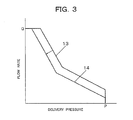
FIG. 1 is a hydraulic circuit diagram illustrating a first embodiment of the exhaust gas purification system according to the present invention for the construction machine,FIG. 2 is a block diagram showing the construction of an essential part of a controller arranged in the first embodiment illustrated inFIG. 1 , andFIG. 3 is a diagram depicting characteristics available from the first embodiment of the present invention. - The first embodiment of the present invention as illustrated in
FIG. 1 is arranged on a construction machine, for example,a hydraulic excavator. This hydraulic excavator is provided with anengine 1 and a variable displacementhydraulic pump 2 driven by theengine 1, and is torque-controlled such that an absorption torque of thehydraulic pump 2 does not exceed an output torque of theengine 1. The hydraulic excavator is also provided with a revolution speed instructingdevice 3 for instructing a target revolution speed of theengine 1, aregulator 4 for controlling a displacement of thehydraulic pump 2, amain relief valve 5 for specifying a maximum delivery pressure of thehydraulic pump 2, a revolution control means 6 for controlling a revolution speed of theengine 1, and acontroller 7 for outputting to the revolution control means 6 a control signal corresponding to the target revolution speed instructed by the revolution speed instructingdevice 3 and also for outputting a drive signal to drive theregulator 4. - The exhaust gas purification system is further provided with a
hydraulic drive circuit 8 to which pressure oil delivered from thehydraulic pump 2 is fed. - The
hydraulic drive circuit 8 includes hydraulic equipment such as hydraulic actuators for a boom cylinder, arm cylinder and the like required to drive attachments such as a boom, arm and the like, or hydraulic actuators such as a swing motor and travel motor for driving a swing upperstructure and travel base; and also directional control valves for controlling operations of these hydraulic actuators. - The exhaust gas purification system according to the first embodiment, which is arranged on such a hydraulic excavator, is provided with an exhaust gas control means 9 for performing treatment to purify nitrogen oxides in exhaust gas emitted from the
engine 1, a reducing agent solution reservoir for storing a reducing agent solution, for example, urea aqueous solution to be fed to the exhaust gas control means 9, specifically a ureaaqueous solution reservoir 10, and a remaining amount detection means 11 for detecting a remaining amount of the urea aqueous solution stored in the ureaaqueous solution reservoir 10. - Also provided is an alarm means, for example, a
warning lamp 12 for giving a warning to the effect that a replenishment of the urea aqueous solution is required, when the remaining amount of the urea aqueous solution as detected by the remaining amount detection means 11 has decreased to a first predetermined amount A1 to be mentioned subsequently herein. - As will also be mentioned subsequently herein, still further provided is a state quantity control means, for example, a pump absorption torque control means for performing a control to reduce a state quantity relating to the drive of the
hydraulic pump 2, for example, a pump absorption torque to a predetermined value in a range that an operation of a hydraulic actuator included in the above-mentionedhydraulic drive circuit 8 becomes feasible, as the remaining amount of the urea aqueous solution in the ureaaqueous solution reservoir 10 as detected by the remaining amount detection means 11 becomes smaller from the first predetermined amount A. This pump absorption torque control means is included in thecontroller 7. - As shown in
FIG. 2 , thecontroller 7 is internally provided with an ON/OFFsignal generator unit 7a for outputting an ON signal or OFF signal to thewarning lamp 12 responsive to a detection signal outputted from the remaining amount detection means 11. This ON/OFFsignal generator unit 7a outputs an OFF signal until the remaining amount in the ureaaqueous solution reservoir 10 decreases to the first predetermined amount A, but outputs an ON signal when the remaining amount decreases below the first predetermined amount A. - The
controller 7 is also internally provided with a pump absorptiontorque computing unit 7b for computing a maximum pump absorption torque M of thehydraulic pump 2 that does not exceed an output torque of theengine 1 at the time of normal working. - In particular, the
controller 7 is provided with afunction generator unit 7c, and aminimum selector unit 7d for selecting smaller one of a signal S1 outputted from thefunction generator unit 7c and a signal S2 outputted from the above-mentioned pump absorptiontorque computing unit 7b and outputting the smaller signal as a drive signal to theregulator 4. By thesefunction generator unit 7c andminimum selector unit 7d, a pump absorption torque control means as the above-mentioned state quantity control means is constructed. - The
function generator unit 7c is designed to be in a functional relation that it outputs a signal S1, which corresponds to the maximum pump absorption torque M until the remaining amount in the ureaaqueous solution reservoir 10 decreases to the first predetermined amount A, outputs a signal S1, the value of which gradually decreases in accordance with a decrease in the remaining amount, when the remaining amount has deceased to and below the first predetermined amount A, and outputs a signal S1, which corresponds to a limited torque m, for example, 70% of the maximum pump absorption torque M when the remaining amount has decreased to and below a second predetermined value B smaller than the first predetermined amount A. It is to be noted that the second predetermined value B, which gives the above-mentioned limited torque m, is a predetermined value in a range that an operation of the hydraulic actuator included in thehydraulic drive circuit 8 becomes feasible. - In the first embodiment constructed as described above, the urea aqueous solution is sufficiently fed to the exhaust gas control means 9 until the remaining amount of the urea aqueous solution in the urea
aqueous solution reservoir 10 decreases to the first predetermined amount A. As a consequence, nitrogen oxides in exhaust gas emitted from theengine 1 can be purified to emit clean exhaust gas. During this purification, a detection signal of the remaining amount detection means 11 is inputted to thecontroller 7, and from the ON/OFFsignal generator unit 7a depicted inFIG. 2 , an OFF signal is outputted to thewarning lamp 12 so that thewarning lamp 12 is maintained in an off state. On the other hand, the signal S2 corresponding to the maximum pump absorption torque M is outputted from thefunction generator unit 7c, and at theminimum selector unit 7d, a drive signal corresponding to the maximum absorption torque M is outputted from the signal S1 and signal S2 to theregulator 4. As a result, theregulator 4 is actuated to control the swash angle of thehydraulic pump 2 such that a maximum pump absorption torque M in a range not exceeding an output torque of theengine 1 is given. Acharacteristic line 13 inFIG. 3 is a P-Q characteristic line corresponding to the maximum pump absorption torque M at this time. - When the urea aqueous solution in the urea
aqueous solution reservoir 10 decreases from the above-mentioned state and the remaining amount of the urea aqueous solution as detected by the remaining amount detection means 11 decreases to the first predetermined amount A, an ON signal is outputted from the ON/OFFsignal generator unit 7a of thecontroller 7 to thewarning lamp 12. As a result, thewarning lamp 12 is turned on. As the remaining amount of the urea aqueous solution further decreases from the first predetermined amount A, the signal S1 outputted from thefunction generator unit 7c becomes gradually smaller in value than the maximum pump absorption torque M while thewarning lamp 12 remains on. This smaller value is selected at theminimum selector unit 7d, and a drive signal corresponding to the smaller value is outputted to theregulator 4. As a result, the swash angle of thehydraulic pump 2 is controlled to become gradually smaller so that the P-Q characteristic shown inFIG. 3 , that is, the pump absorption torque is controlled to become gradually smaller as indicated by an arrow inFIG. 3 . - When the remaining amount in the urea
aqueous solution reservoir 10 further decreases and the remaining amount detected by the remaining amount detection means 11 decreases to and below the second predetermined amount B, the warninglamp 12 remains on and the signal S1 outputted from thefunction generator unit 7c takes a value corresponding to the limited torque m. This limited torque m is selected at theminimum selector unit 7d, and a drive signal corresponding to the limited torque m is outputted to theregulator 4. As a result, the swash angle of thehydraulic pump 2 is limited to have a still smaller value so that the P-Q characteristic shown inFIG. 3 , specifically the pump absorption torque becomes as shown by acharacteristic line 14. - When this state is reached, the time required for a single working cycle such as, for example, work that digs out earth and stones by the hydraulic excavator and loads the dug earth and stones on a dump truck becomes longer compared with that at the time of normal working, resulting in reduced working performance.
- Even when the remaining amount of the urea aqueous solution in the urea
aqueous solution reservoir 10 has decreased to and below the second predetermined amount B as mentioned above, the purification of exhaust gas from theengine 1 can be continued to emit clean exhaust gas with a load reduced as a result of a decrease in pump absorption torque. - According to the first embodiment, there are provided, as described above, the exhaust gas control means 9 for conducting treatment to purify nitrogen oxides in exhaust gas emitted from the
engine 1, which drives thehydraulic pump 2, and the ureaaqueous solution reservoir 10 for storing urea aqueous solution to be fed to the exhaust gas control means 9. It is, therefore, possible to purify exhaust gas emitted from theengine 1. - Owing to the provision of the remaining amount detection means 11 for detecting the remaining amount of the urea aqueous solution stored in the urea aqueous solution reservoir 10, the warning lamp 12 for giving a warning to the effect that a replenishment of the urea aqueous solution is required when the remaining amount of the urea aqueous solution as detected by the remaining amount detection means 11 has decreased to the first predetermined amount A, and the function generator unit 7c and minimum selector unit 7d included in the pump absorption torque control means for performing control to decrease the pump absorption torque, which relates to the drive of the hydraulic pump 2, to the predetermined value in the range that the operation of the hydraulic actuator included in the hydraulic drive circuit 8 becomes feasible, specifically to the limited torque m which is, for example, a value of 70% of the maximum pump absorption torque M as the remaining amount of the urea aqueous solution as detected by the remaining amount detection means 11 becomes smaller from the first predetermined amount A, the purification of exhaust gas from the engine 1 can be still continued with a load reduced as a result of a decrease in the state quantity relating to the hydraulic pump 2, specifically the pump absorption load when the remaining amount of the urea aqueous solution in the urea aqueous solution reservoir 10 has decreased to and below the first predetermined amount A.
- Concurrently, the warning
lamp 12 turns on, and in addition, the working performance is reduced. Therefore, a replenishment of the urea aqueous solution is urged. Further, the work can still be continued without an engine stall although within the limited range. Accordingly, the present invention can realize a system suited for a construction machine. -
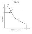
FIG. 4 is a block diagram showing the construction of an essential part of a controller arranged in a second embodiment of the present invention, andFIG. 5 is a diagram depicting characteristics available from the second embodiment of the present invention. - In addition to an ON/OFF
signal generator unit 7a equivalent to that in the first embodiment, the second embodiment of the present invention is provided, in thecontroller 7, with a pump deliveryrate computing unit 7e for computing a delivery rate of thehydraulic pump 2 corresponding to a revolution speed of theengine 1 and outputting a signal S4 corresponding to the computed value, afunction generator unit 7f for outputting a signal S3 corresponding to a flow rate which corresponds to a value indicative of a remaining amount of the urea aqueous solution in the ureaaqueous solution reservoir 10, and aminimum selector unit 7g for selecting smaller one of the signal S3 outputted from thefunction generator unit 7f and the signal S4 outputted from the pump deliveryrate computing unit 7e. - The above-mentioned
function generator unit 7f andminimum selector unit 7g make up a flow rate control means for performing control to decrease a state quantity relating to a drive of thehydraulic pump 2, for example, a flow rate to be delivered from thehydraulic pump 2 to a predetermined value in a range that an operation of the hydraulic actuator included in thehydraulic drive circuit 8 becomes feasible, that is, a state quantity control means, as the remaining amount of the urea aqueous solution as detected by the remaining amount detection means 11 becomes smaller from a predetermined amount. - The
function generator unit 7f is designed to be in a functional relation that it outputs a signal S3, which corresponds to a maximum flow rate Q corresponding to a revolution speed of theengine 1 until the remaining amount in the ureaaqueous solution reservoir 10 decreases to a first predetermined amount A, outputs a signal S3, the value of which gradually decreases in accordance with a decrease in the remaining amount in the ureaaqueous solution reservoir 10, when the remaining amount has deceased to and below the first predetermined amount A, and outputs a signal S3, which corresponds to a limited flow rate q, for example, 70% of the maximum flow rate Q at the time of normal working when the remaining amount in the ureaaqueous solution reservoir 10 has decreased to and below a second predetermined amount B smaller than the first predetermined amount A. It is to be noted that the second predetermined amount B, which gives the above-mentioned limited flow rate q, is a predetermined value in a range that an operation of the hydraulic actuator included in thehydraulic drive circuit 8 becomes feasible. - The remaining construction is similar to that of the above-described first embodiment.
- In the second embodiment constructed as described above, the urea aqueous solution is sufficiently fed as in the first embodiment until the remaining amount of the urea aqueous solution in the urea
aqueous solution reservoir 10 decreases to the first predetermined amount A. Therefore, nitrogen oxides in exhaust gas can be purified to emit clean exhaust gas. Further, the warninglamp 12 is maintained in an off state. Because the signal S3 outputted from thefunction generator unit 7f and the signal S4 outputted from the pump deliveryrate computing unit 7e of thecontroller 7 take the same value, a drive signal corresponding to the maximum flow rate Q, which corresponds to the revolution speed of theengine 1, is outputted from theminimum selector unit 7g to theregulator 4. As a consequence, the P-Q characteristic line inFIG. 5 becomes acharacteristic line 13 as in the above-mentioned first embodiment. - When the urea aqueous solution in the urea
aqueous solution reservoir 10 decreases from such a state and the remaining amount of the urea aqueous solution as detected by the remaining amount detection means 11 decreases to the first predetermined amount A, the warninglamp 12 is turned on. As the remaining amount of the urea aqueous solution further decreases from the first predetermined amount A, the signal S3 outputted from thefunction generator unit 7f becomes gradually smaller in value than the maximum flow rate Q while the warninglamp 12 remains on. This smaller value is selected at theminimum selector unit 7g, and a drive signal corresponding to the smaller value is outputted to theregulator 4. As a result, the P-Q characteristic shown inFIG. 5 , that is, the flow rate of thehydraulic pump 2 is controlled to become gradually smaller as indicated by an arrow inFIG. 5 . - When the urea aqueous solution in the urea
aqueous solution reservoir 10 further decreases to or below the second predetermined amount B, the warninglamp 12 remains on and the signal S3 outputted from thefunction generator unit 7f takes a value corresponding to the limited flow rate q. A drive signal corresponding to this value is outputted from theminimum selector unit 7g to theregulator 4. As a result, the P-Q characteristic shown inFIG. 5 becomes as shown by acharacteristic line 15. - When this state is reached, the maximum flow rate to be fed to the hydraulic actuator included in the
hydraulic drive circuit 8 is limited to the limited flow rate q. This develops a situation that the operation speed of the hydraulic actuator becomes slower than that at the time of normal working, leading to a reduction in working performance. - Even when the remaining amount of the urea aqueous solution in the urea
aqueous solution reservoir 10 has decreased to and below the second predetermined amount B as mentioned above, the purification of exhaust gas from theengine 1 can be continued to emit clean exhaust gas with a load reduced as a result of a decrease in the flow rate delivered from thehydraulic pump 2. - The second embodiment constructed as described above can also clean exhaust gas emitted from the
engine 1 like the above-described first embodiment. - When the remaining amount of the urea aqueous solution as detected by the remaining amount detection means 11 has decreased to or below the first predetermined amount A, the warning
lamp 12 is turned on. - When the remaining amount of the urea aqueous solution as detected by the remaining amount detection means 11 decreases to or below the first predetermined amount A, the flow rate to be delivered from the
hydraulic pump 2 is limited so that it gradually decreases. Below the second predetermined amount B, the flow rate decreases to the limited flow rate q, that is, 70% of the maximum flow rate Q. The purification of exhaust gas from theengine 1 can be still continued with a load reduced even when the remaining amount of the urea aqueous solution has decreased to or below the second predetermined amount B. - As the warning
lamp 12 turns on as mentioned above and in addition, the working performance is reduced, a replenishment of the urea aqueous solution is urged. By feeding pressure oil to the hydraulic actuator, the work can still be continued without an engine stall although within the limited range. -
FIG. 6 is a hydraulic circuit diagram illustrating a third embodiment of the present invention, andFIG. 7 is a block diagram showing the construction of an essential part of a controller arranged in the third embodiment of the present invention. - As illustrated in
FIG. 6 , the third embodiment of the present invention is provided, in addition to the construction of the above-described first embodiment, with a solenoidvalve 16 capable of controlling the delivery pressure of themain relief valve 5 and apilot pump 17 capable of feeding a pilot pressure to thesolenoid valve 16. - In addition to an ON/OFF
signal generator unit 7 equivalent to that in the first embodiment, thecontroller 7 is also internally provided with a function generator unit 7h for outputting a signal S5 corresponding to a delivery pressure, which corresponds to a value indicative of the remaining amount of the urea aqueous solution in the ureaaqueous solution reservoir 10, and afunction generator unit 7i for outputting a current, which corresponds to the signal S5 outputted from the function generator unit 7h, as a drive signal to thesolenoid valve 16. - The above-mentioned
function generator units 7h,7i,solenoid valve 16 andpilot pump 17 make up a delivery pressure control means for performing control to decrease a state quantity relating to a drive of thehydraulic pump 2, for example, the delivery pressure of pressure oil delivered from thehydraulic pump 2 to a predetermined value in a range that an operation of the hydraulic actuator included in thehydraulic drive circuit 8 becomes feasible, that is, a state quantity control means, as the remaining amount of the urea aqueous solution as detectedby the remaining amount detection means 11 becomes smaller from a predetermined amount. - The function generator unit 7h is designed to be in a functional relation that it outputs a signal S5, which corresponds to a preset maximum delivery pressure P at the time of normal working of the
hydraulic pump 2 until the remaining amount in the ureaaqueous solution reservoir 10 decreases to a first predetermined amount A, outputs a signal S5, the value of which gradually decreases in accordance with a decrease in the remaining amount in the ureaaqueous solution reservoir 10, when the remaining amount has deceased to and below the first predetermined amount A, and outputs a signal, which corresponds to a limited delivery pressure Ps, for example, 70% of the maximum delivery pressure P at the time of normal working when the remaining amount in the ureaaqueous solution reservoir 10 has decreased to and below a second predetermined amount B smaller than the first predetermined amount A. - It is to be noted that the second predetermined amount B, which gives the above-mentioned limited delivery pressure Ps, is a predetermined value in a range that an operation of the hydraulic actuator included in the
hydraulic drive circuit 8 becomes feasible. - Corresponding to the value of the
signal 5 outputted from the function generation unit 7h, that is, the delivery pressure, thefunction generator unit 7i outputs as a drive signal a current in a range of from a maximum current SM to a limited current Sm smaller than the maximum current SM. - The remaining construction is similar to that of the above-described first embodiment.
- In the third embodiment constructed as described above, the urea aqueous solution is sufficiently fed as in the first embodiment until the remaining amount of the urea aqueous solution in the urea
aqueous solution reservoir 10 decreases to the first predetermined amount A. Therefore, nitrogen oxides in exhaust gas can be purified to emit clean exhaust gas. Further, the warninglamp 12 is maintained in an off state. From the function generator unit 7h of thecontroller 7, the signal S5 corresponding to the maximum delivery pressure P at the time of normal working is outputted, and responsive to this signal S5, a drive signal corresponding to a maximum current SM is outputted from thefunction generator unit 7i to thesolenoidvalve 6. As a consequence, the preset pressure of themain relief valve 5 is maintained at a high pressure preset for the normal work. - When the urea aqueous solution in the urea
aqueous solution reservoir 10 decreases from such a state and the remaining amount of the urea aqueous solution as detected by the remaining amount detection means 11 decreases to the first predetermined amount A, the warninglamp 12 is turned on. As the remaining amount of the urea aqueous solution further decreases from the first predetermined amount A, the signal S5 outputted from the function generator unit 7h becomes gradually smaller in value than the maximum delivery pressure P while the warninglamp 12 remains on. Responsive to this smaller value, a drive signal corresponding to a current smaller than the maximum current SM is outputted from thefunction generator unit 7i to thesolenoid valve 16. As a result, thesolenoid valve 16 is actuated to apply the pilot pressure of thepilot pump 17 to the control portion of themain relief valve 5 via thesolenoid valve 16, and themain relief valve 5 is controlled such that its preset pressure becomes gradually lower than the maximum delivery pressure P. - When the urea aqueous solution in the urea
aqueous solution reservoir 10 further decreases to or below the second predetermined amount B, the warninglamp 12 remains on and the signal S5 outputted from the function generator unit 7h takes a value corresponding to the limited delivery pressure s. A drive signal corresponding to the limited current Sm, which corresponds to this value, is outputtedfromthefunction generator unit 7i to thesolenoid valve 16. The preset pressure of themain relief valve 5 is, therefore, becomes the limited delivery pressure Ps by a pilot pressure fed through thesolenoid valve 16. - When this state is reached, no maximum force can be produced upon operation of the hydraulic actuator included in the
hydraulic drive circuit 8, thereby developing, for example, a situation such that digging of a hard ground can no longer be performed although it was feasible at the time of normal working, and hence leading to a reduction in working performance - Even when the remaining amount of the urea aqueous solution in the urea
aqueous solution reservoir 10 has decreased to and below the second predetermined amount B as mentioned above, the purification of exhaust gas from theengine 1 can be continued to emit clean exhaust gas with a load reduced as a result of a decrease in the maximum delivery pressure of pressure oil delivered from thehydraulic pump 2. - This embodiment constructed as described above can also clean exhaust gas emitted from the
engine 1 like the above-described first embodiment. - When the remaining amount of the urea aqueous solution as detected by the remaining amount detection means 11 has decreased to or below the first predetermined amount A, the warning
lamp 12 is turned on as in the first embodiment. - When the remaining amount of the urea aqueous solution as detected by the remaining amount detection means 11 decreases to or below the first predetermined amount A, the delivery pressure of the
hydraulic pump 2 gradually decreases from the maximum delivery pressure Pm, and below the second predetermined amount B, the delivery pressure decreases to the limited delivery pressure Ps, that is, 70% of the maximum delivery pressure P. The purification of exhaust gas from theengine 1 can be still continued with a load reduced even when the remaining amount of the urea aqueous solution has decreased to or below the second predetermined amount B. - As the warning
lamp 12 turns on as mentioned above and in addition, the working performance is reduced, a replenishment of the urea aqueous solution is also urged in this third embodiment. By feeding pressure oil to the hydraulic actuator, the work can still be continued without an engine stall although within the limited range. - In addition to the above-described embodiments, it is also possible to control an element relating to the operation of the hydraulic actuator, especially the revolution speed of the engine.
- A description will now be made about an exhaust gas purification system designed to limit the maximum revolution speed of an engine such that, when a reducing agent solution has become smaller than a predetermined amount as described above, the maximum revolution speed is gradually reduced to a predetermined value in a range that an operation of the hydraulic actuator becomes feasible.
- This exhaust gas purification system is characterized in that it is arranged on a construction machine provided with an engine, a hydraulic pump driven by the engine, and a hydraulic drive circuit including plural hydraulic actuators to which pressure oil delivered from the hydraulic pump is fed and that it comprises an exhaust gas control means for conducting treatment to purify nitrogen oxides in exhaust gas emitted from the engine, a reducing agent solution reservoir for storing a reducing agent solution to be fed to the exhaust gas control means, a remaining amount detection means for detecting a remaining amount of the reducing agent solution stored in the reducing agent solution reservoir, an alarm means for giving a warning to an effect that a replenishment of the reducing agent solution is required, when the remaining amount of the reducing agent solution as detectedby the remaining amount detectionmeans has decreased to a predetermined amount, and an engine revolution speed limiting means for limiting a maximum revolution speed of the engine such that, when the remaining amount of the reducing agent solution as detected by the remaining amount detection means has become smaller from the predetermined amount, it is gradually reduced in accordance with the decrease in the remaining amount to a predetermined value in a range that an operation of the hydraulic actuator becomes feasible.
- By constructing as described above, the reducing agent solution is sufficiently fed to the exhaust gas control means until the remaining amount of the reducing agent solution in the reducing agent solution reservoir decreases to the predetermined amount. As a consequence, nitrogen oxides in exhaust gas emitted from the engine can be purified to emit clean exhaust gas. When the remaining amount of the reducing agent solution in the reducing agent solution reservoir has decreased to the predetermined amount, this decrease is detected by the remaining amount detection means, and a warning is given by the alarm means. Further, the engine revolution speed limiting means is actuated responsive to the detection by the remaining amount detection means to perform a control that gradually reduces the maximum revolution speed of the engine compared with that at the time of normal working, that is, a control that reduces the maximum revolution speed of the engine to a predetermined value in a range that an operation of the hydraulic actuator becomes feasible.
- As a consequence, even when the remaining amount of the reducing agent solution in the reducing agent solution reservoir has decreased to or below the predetermined amount, the purification of exhaust gas from the engine can still be continued to emit clean exhaust gas with a load reduced as a result of the reduction of the maximum revolution speed of the engine. Further, the need for a replenishment of the reducing agent solution is urged by a reduction in working performance in addition to the above-mentioned warning. Furthermore, the work can still be continued, because owing to the control by the engine revolution speed control means, the performance of the work is gradually reduced in accordance with the decrease in the remaining amount of the reducing agent solution and an abrupt fluctuation in the work can hence be inhibited, and the operation of the hydraulic actuator remains feasible in the limited range, although the working performance is reduced as mentioned above.
- In the above-described purification system, the reducing agent solution may comprise urea aqueous solution.
- In the above-described purification system, the alarm means may comprise a warning lamp.
- The present invention can purify exhaust gas emitted from the engine, because it is provided with the exhaust gas control means for conducting treatment to purify nitrogen oxides in the exhaust gas emitted from the engine that drives the hydraulic pump and also with the reducing agent solution reservoir for storing the reducing agent solution to be fed to the exhaust gas control means. The present invention is also provided with the remaining amount detection means for detecting the remaining amount of the reducing agent solution stored in the reducing agent solution reservoir, with the alarm means for giving a warning to the effect that a replenishment of the reducing agent solution is required, when the remaining amount of the reducing agent solution as detectedby the remaining amount detectionmeans has decreased to the predetermined amount, and also with the engine revolution speed limiting means for limiting the maximum revolution speed of the engine such that, when the remaining amount of the reducing agent solution as detected by the remaining amount detection means has become smaller from the predetermined amount, it is gradually reduced in accordance with the decrease in the remaining amount to the predetermined value in the range that an operation of the hydraulic actuator becomes feasible. When the remaining amount of the reducing agent solution in the reducing agent solution reservoir has decreased to and below the predetermined amount, the purification of exhaust gas from the engine can, therefore, be still continued with a load reduced as a result of the reduction in the maximum revolution speed of the engine, and moreover, a warning is given and a reduction takes place in working performance. By these warning and reduction, a replenishment of the reducing agent solution is thus urged. In addition, the working performance can be gradually reduced in accordance with the decrease in the remaining amount of the reducing agent solution, an abrupt fluctuation in the work can be inhibited. Therefore, the work can still be continued although within the limited range. Accordingly, the present invention can realize a system suited for a construction machine.
- A practical mode will hereinafter be described with reference to the drawings.
- FIG. 81 is a hydraulic circuit diagram illustrating a still further embodiment of the exhaust gas purification system according to the present invention for the construction machine, and
FIG. 9 is a block diagram showing the construction of an essential part of a controller arranged in the still further embodiment illustrated inFIG. 8 . - The still further embodiment of the present invention as illustrated in
FIG. 8 is arranged on a construction machine, for example,a hydraulic excavator. This hydraulic excavator is provided with anengine 101 and a variable displacementhydraulic pump 102 driven by theengine 101, and is torque-controlled such that an absorption torque of thehydraulic pump 102 does not exceed an output torque of theengine 101. The hydraulic excavator is also provided with a revolutionspeed instructing device 103 for instructing a target revolution speed of theengine 101, aregulator 104 for controlling a displacement of thehydraulic pump 102, amain relief valve 105 for specifying a maximum delivery pressure of thehydraulic pump 102, a revolution control means 106 for controlling a revolution speed of theengine 101, and acontroller 107 for outputting to the revolution control means 106 a control signal corresponding to the target revolution speed instructed by the revolutionspeed instructing device 103 and also for outputting a drive signal to drive theregulator 104. - The exhaust gas purification system is further provided with a
hydraulic drive circuit 108 to which pressure oil delivered from thehydraulic pump 102 is fed. Thishydraulic drive circuit 108 includes hydraulic equipment such as hydraulic actuators for a boom cylinder, arm cylinder and the like required to drive attachments such as a boom, arm and the like, or hydraulic actuators such as a swing motor and travel motor for driving a swing upperstructure and travel base; and also directional control valves for controlling operations of these hydraulic actuators. - The exhaust gas purification system according to this embodiment, which is arranged on such a hydraulic excavator, is provided with an exhaust gas control means 109 for performing treatment to purify nitrogen oxides in exhaust gas emitted from the
engine 101, a reducing agent solution reservoir for storing a reducing agent solution, for example, urea aqueous solution to be fed to the exhaust gas control means 109, specifically a ureaaqueous solution reservoir 110, and a remaining amount detection means 111 for detecting a remaining amount of the urea aqueous solution stored in the ureaaqueous solution reservoir 110. - Also provided is an alarmmeans, for example, an
warning lamp 112 for giving a warning to the effect that a replenishment of the urea aqueous solution is required, when the remaining amount of the urea aqueous solution as detected by the remaining amount detection means 111 has decreased to a first predetermined amount A1 to be mentioned subsequently herein. - As will also be mentioned subsequently herein, still further provided is an engine revolution speed limiting means for limiting a maximum revolution speed of the
engine 101 such that, when the remaining amount of the reducing agent solution in the ureaaqueous solution reservoir 110 as detected by the remaining amount detection means 111 has become smaller from the predetermined first amount A, it is reduced in accordance with the decrease in the remaining amount to a predetermined value in a range that an operation of the above-mentioned hydraulic actuator included in thehydraulic drive circuit 108 becomes feasible. This engine revolution speed limiting means is included in thecontroller 107. - As shown in
FIG. 9 , thecontroller 7 is internally provided with an ON/OFFsignal generator unit 107a for outputting an ON signal or OFF signal to thewarning lamp 112 responsive to a detection signal outputted from the remaining amount detection means 111. This ON/OFFsignal generator unit 107a outputs an OFF signal until the remaining amount in the ureaaqueous solution reservoir 110 decreases to the first predetermined amount A, but outputs an ON signal when the remaining amount decreases below the first predetermined amount A. - The
controller 107 is also internally provided with an engine revolutionspeed computing unit 107b for controlling the maximum revolution speed of theengine 101 to a target revolution speed instructed by the revolutionspeed instructing unit 103 in normal working. - In particular, the
controller 107 is provided with afunction generator unit 107c, and aminimum selector unit 107d for selecting smaller one of a signal S1 outputted from thefunction generator unit 107c and a signal S2 outputted from the above-mentioned engine revolutionspeed computing unit 107b and outputting the smaller signal as a drive signal to theregulator 104. By thesefunction generator unit 107c andminimum selector unit 107d, an engine revolution number limiting means is constructed. - The
function generator unit 107c is designed to be in a functional relation that it outputs a signal S1, which corresponds to the maximum revolution speed N of theengine 101 in normal time until the remaining amount in the ureaaqueous solution reservoir 110 decreases to the first predetermined amount A, outputs a signal S1 which, when the remaining amount has deceased to and below the first predetermined amount A, gradually reduces the maximum revolution speed of theengine 101 in accordance with the decrease in the remaining amount, and outputs a signal S1, which corresponds to a limited revolution speed n, for example, 70% of the maximum revolution speed N of theengine 101 in normal working when the remaining amount has decreased to and below a second predetermined value B smaller than the first predetermined amount A. It is to be noted that the second predetermined amount B, which gives the above-mentioned limited revolution speed n, is a predetermined value in a range that an operation of the hydraulic actuator included in thehydraulic drive circuit 108 becomes feasible. - In the this embodiment constructed as described above, the urea aqueous solution is sufficiently fed to the exhaust gas control means 109 until the remaining amount of the urea aqueous solution in the urea
aqueous solution reservoir 110 decreases to the first predetermined amount A. As a consequence, nitrogen oxides in exhaust gas emitted from theengine 101 can be purified to emit clean exhaust gas. During this purification, a detection signal of the remaining amount detection means 111 is inputted to thecontroller 107, and from the ON/OFFsignal generator unit 107a depicted inFIG. 2 , an OFF signal is outputted to thewarning lamp 112 so that thewarning lamp 112 is maintained in an off state. On the other hand, the signal S2 corresponding to the maximum revolution speed N is outputted from thefunction generator unit 107c, and at theminimum selector unit 107d, a drive signal corresponding, for example, to the maximum revolution speed N of theengine 101 is outputted from the signal S1 and signal S2 to theregulator 104. As a result, theregulator 104 is actuated to control the swash angle of thehydraulic pump 102 such that a maximum pump absorption torque in a range not exceeding an output torque of theengine 101 is given. - When the urea aqueous solution in the urea
aqueous solution reservoir 110 decreases from the above-mentioned state and the remaining amount of the urea aqueous solution as detected by the remaining amount detection means 111 decreases to the first predetermined amount A, an ON signal is outputted from the ON/OFFsignal generator unit 107a of thecontroller 7 to thewarning lamp 112. As a result, the warninglamp 112 is turned on. As the remaining amount of the urea aqueous solution further decreases from the first predetermined amount A, the signal S1 outputted from thefunction generator unit 107c becomes gradually lower in value than the maximum revolution speed N of theengine 101 in normal working while thewarning lamp 112 remains on. For example, this lower revolution speed is selected at theminimum selector unit 107d, and a drive signal corresponding to the lower revolution speed is outputted to theregulator 104. As a result, the swash angle of thehydraulic pump 102 is controlled to become gradually smaller so that the flow rate of pressure oil delivered from thehydraulic pump 102 gradually decreases. - When the remaining amount in the urea
aqueous solution reservoir 110 further decreases and the remaining amount detectedby the remaining amount detectionmeans 111 decreases to and below the second predetermined amount B, the warninglamp 112 remains on and the signal S1 outputted from thefunction generator unit 107c takes a value corresponding to the limited revolution speed n. This limited revolution speed n is selected at theminimum selector unit 107d, and a drive signal corresponding to the limited revolution speed n is outputted to theregulator 104. As a result, the swash angle of thehydraulic pump 102 is limited to have a still smaller value so that the flow rate of pressure oil delivered from thehydraulic pump 102 decreases. When this state is reached, the operation speed of the hydraulic actuator becomes slower compared with that at the time of normal working, resulting in reduced working performance. - Even when the remaining amount of the urea aqueous solution in the urea
aqueous solution reservoir 110 has decreased to and below the second predetermined amount B as mentioned above, the purification of exhaust gas from theengine 101 can be continued to emit clean exhaust gas with a load reduced as a result of a reduction in the maximum revolution speed of theengine 101. - According to this embodiment, there are provided, as described above, the exhaust gas control means 109 for conducting treatment to purify nitrogen oxides in exhaust gas emitted from the
engine 101, which drives thehydraulic pump 101, and the ureaaqueous solution reservoir 110 for storing urea aqueous solution to be fed to the exhaust gas control means 109. It is, therefore, possible to purify exhaust gas emitted from theengine 101. - Owing to the provision of the remaining amount detection means 111 for detecting the remaining amount of the urea aqueous solution stored in the urea aqueous solution reservoir 110, the warning lamp 112 for giving a warning to the effect that a replenishment of the urea aqueous solution is required when the remaining amount of the urea aqueous solution as detected by the remaining amount detection means 111 has decreasedtothe first predeterminedamount A, and the function generator unit 107c and minimum selector unit 107d included in the engine revolution speed control means for performing control to gradually decrease the maximum revolution speed of the engine 101 to the predetermined value in the range that the operation of the hydraulic actuator included in the hydraulic drive circuit 108 becomes feasible, specifically to the limited revolution speed n which is, for example, a value of 70% of the maximum revolution speed N of the engine 101 at the time of normal working as the remaining amount of the urea aqueous solution as detected by the remaining amount detection means 111 becomes smaller from the first predetermined amount A, the purification of exhaust gas from the engine 1 can be still continued with a load reduced as a result of a reduction in the maximum revolution speed of the engine 101 when the remaining amount of the urea aqueous solution in the urea aqueous solution reservoir 110 has decreased to and below the first predetermined amount A.
- As the
warning lamp 112 also turns on and in addition, the working performance is also reduced, a replenishment of the urea aqueous solution is urged. In addition, the working performance can be gradually reduced in accordance with the decrease in the remaining amount of the urea aqueous solution, an abrupt fluctuation in the work can be inhibited. Therefore, the work can still be continued although within the limited range. Accordingly, the present invention can realize a system suited for this hydraulic excavator. -
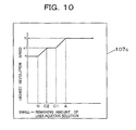
FIG. 10 is a diagram depicting a function generator unit included in a yet further embodiment of the present invention. - This yet further embodiment is different from the above-described still further embodiment in the setting of a function at a
function generator unit 107c included in acontroller 107 and constituting the engine revolution speed limiting means. The remaining construction is equivalent to that in the above-described still further embodiment. - The
function generator unit 107c in thecontroller 107 arranged in the yet further embodiment depicted inFIG. 10 is set in a functional relation that the maximum revolution speed of theengine 101 is set at the maximum revolution speed N for normal working until the remaining amount of the urea aqueous solution decreases to the first predetermined amount A; that, when the remaining amount becomes the first predetermined amount A, the maximum speed is gradually reduced to n1 in accordance with the decrease in the remaining amount until the remaining amount decreases to a predetermined amount C1; that the above-mentioned maximum speed n1 is maintained while the remaining amount decreases from the predetermined amount C1 to another predetermined amount C2; that, while the remaining amount decreases from the predetermined amount C2 to a second predetermined amount B, the maximum revolution speed is gradually reduced to a limited revolution speed n in accordance with the decrease in the remaining amount; and that, when the remaining amount decreases to and below the second predetermined amount B, the limited revolution speed n is maintained. Described specifically, the maximum revolution number is set in a functional relation that, as the remaining amount of the urea aqueous solution decreases, the maximum revolution speed is gradually reduced stepwise from the maximum revolution number N for normal working to the limited revolution number n which is, for example, a value of 70% of the maximum revolution speed N. - The yet further embodiment, which is provided with the
controller 107 having thefunction generator unit 107c of the functional relation set as described above, can also bring about similar advantageous effects as the above-described embodiments, because it is designed such that, as the remaining amount of the urea aqueous solution decreases, the maximum revolution speed of theengine 101 is gradually reduced in accordance with the remaining amount within the range that the operation of the hydraulic actuator included in thehydraulic drive circuit 108 becomes feasible. -
- [
FIG. 1 ] A hydraulic circuit diagram illustrating a first embodiment of an exhaust gas purification system according to the present invention for a construction machine. - [
FIG. 2 ] A block diagram showing the construction of an essential part of a controller arrangedin the first embodiment illustrated inFIG. 1 . - [
FIG. 3 ] A diagram depicting characteristics available from the first embodiment of the present invention. - [
FIG. 4 ] A block diagram showing the construction of an essential part of a controller arranged in a second embodiment of the present invention. - [
FIG. 5 ] A diagram depicting characteristics available from the second embodiment of the present invention. - [
FIG. 6 ] A hydraulic circuit diagram illustrating a third embodiment of the present invention. - [
FIG. 7 ] A block diagram showing the construction of an essential part of a controller arrangedin the thirdembodiment of the present invention. - [
FIG. 8 ] A hydraulic circuit diagram illustrating a still further embodiment of the exhaust gas purification system according to the present invention for the construction machine. - [
FIG. 9 ] A block diagram showing the construction of an essential part of a controller arranged in the still further embodiment illustrated inFIG. 8 . - [
FIG. 10 ] A diagram depicting a function regenerator unit included in a controller arranged in a yet further embodiment of the present invention. -
- 1
- Engine
- 2
- Variable-displacement hydraulic pump
- 3
- Revolution speed instructing device
- 4
- Regulator
- 5
- Main relief valve
- 6
- Revolution control means
- 7
- Controller
- 7a
- ON/OFF signal generator unit
- 7b
- Pump absorption torque computing unit
- 7c
- Function generator unit (pump absorption torque control means)[state quantity control means]
- 7d
- Minimum selector unit (pump absorption torque control means)[state quantity control means]
- 7e
- Pump delivery rate computing unit
- 7f
- Function generator unit (flow rate control means) [state quantity control means]
- 7g
- Minimum selector unit (flow rate control means) [state quantity control means]
- 7h
- Function generator unit (delivery pressure control means) [state quantity control means]
- 7i
- Function generator unit (delivery pressure control means) [state quantity control means]
- 8
- Hydraulic drive circuit
- 9
- Exhaust gas control means
- 10
- Urea aqueous solution reservoir (reducing agent solution reservoir)
- 11
- Remaining amount detection means
- 12
- Warning lamp (alarm means)
- 13
- Characteristic line
- 14
- Characteristic line
- 15
- Characteristic line
- 16
- Solenoid valve (delivery pressure control means) [state quantity control means]
- 17
- Pilot pump (delivery pressure control means) [state quantity control]
- 101
- Engine
- 102
- Variable-displacement hydraulic pump
- 103
- Revolution speed instructing device
- 104
- Regulator
- 105
- Main relief valve
- 106
- Revolution control means
- 107
- Controller
- 107a
- ON/OFF signal generator unit
- 107b
- Engine revolution speed computing unit
- 107c
- Function generator unit (engine revolution speed limiting means)
- 107d
- Minimum selector unit (engine revolution speed limiting means)
- 108
- Hydraulic drive circuit
- 109
- Exhaust gas control means
- 110
- Urea aqueous solution reservoir (reducing agent solution reservoir)
- 111
- Remaining amount detection means
- 112
- Warning lamp (alarm means)
Claims (7)
- An exhaust gas purification system for a construction machine provided with an engine, a hydraulic pump driven by said engine, and a hydraulic drive circuit including plural hydraulic actuators to which pressure oil delivered from said hydraulic pump is fed, comprising:an exhaust gas control means for conducting treatment to purify nitrogen oxides in exhaust gas emitted from said engine,a reducing agent solution reservoir for storing a reducing agent solution to be fed to said exhaust gas control means,a remaining amount detection means for detecting a remaining amount of said reducing agent solution stored in said reducing agent solution reservoir,an alarm means for giving a warning to an effect that a replenishment of said reducing agent solution is required, when said remaining amount of said reducing agent solution as detected by said remaining amount detection means has decreased to a predetermined amount, anda state quantity control means for performing a control to decrease a state quantity relating to a drive of said hydraulic pump to a predetermined value in a range that an operation of said hydraulic actuator becomes feasible, as said remaining amount of said reducing agent solution as detected by said remaining amount detection means becomes smaller from said predetermined amount.
- An exhaust gas purification system for a construction machine provided with an engine, a hydraulic pump driven by said engine, and a hydraulic drive circuit including plural hydraulic actuators to which pressure oil delivered from said hydraulic pump is fed, comprising:an exhaust gas control means for conducting treatment to purify nitrogen oxides in exhaust gas emitted from said engine,a reducing agent solution reservoir for storing a reducing agent solution to be fed to said exhaust gas control means,a remaining amount detection means for detecting a remaining amount of said reducing agent solution stored in said reducing agent solution reservoir,an alarm means for giving a warning to an effect that a replenishment of said reducing agent solution is required, when said remaining amount of said reducing agent solution as detected by said remaining amount detection means has decreased to a predetermined amount, andan engine revolution speed limiting means for limiting a maximum revolution speed of said engine such that, when said remaining amount of said reducing agent solution as detected by said remaining amount detection means has become smaller from said predetermined amount, said maximum revolution speed is gradually reduced in accordance with the decrease in said remaining amount to a predetermined value in a range that an operation of said hydraulic actuator becomes feasible.
- An exhaust gas purification system according to claim 1, wherein:said state quantity relating to said drive of said hydraulic pump is a pump absorption torque, and said state quantity detection means comprises a pump absorption torque control means.
- An exhaust gas purification system according to claim 1, wherein:said state quantity relating to said drive of said hydraulic pump is a flow rate delivered from said hydraulic pump, and said state quantity detection means comprises a flow rate control means.
- An exhaust gas purification system according to claim 1, wherein:said state quantity relating to said drive of said hydraulic pump is a delivery pressure of said hydraulic pump, and said state quantity detection means comprises a delivery pressure control means.
- An exhaust gas purification system according to any one of claims 1-5, wherein said reducing agent solution comprises urea aqueous solution.
- An exhaust gas purification system according to any one of claims 1-6, wherein saidalarmmeans comprises a warning lamp.
Applications Claiming Priority (3)
| Application Number | Priority Date | Filing Date | Title |
|---|---|---|---|
| JP2006153457A JP4847219B2 (en) | 2006-06-01 | 2006-06-01 | Exhaust gas purification equipment for construction machinery |
| JP2006153455A JP4847218B2 (en) | 2006-06-01 | 2006-06-01 | Exhaust gas purification equipment for construction machinery |
| PCT/JP2007/061049 WO2007139177A1 (en) | 2006-06-01 | 2007-05-31 | Exhaust gas purifier of construction machine |
Publications (3)
| Publication Number | Publication Date |
|---|---|
| EP2022954A1 true EP2022954A1 (en) | 2009-02-11 |
| EP2022954A4 EP2022954A4 (en) | 2011-02-16 |
| EP2022954B1 EP2022954B1 (en) | 2012-05-30 |
Family
ID=38778695
Family Applications (1)
| Application Number | Title | Priority Date | Filing Date |
|---|---|---|---|
| EP07744460A Expired - Fee Related EP2022954B1 (en) | 2006-06-01 | 2007-05-31 | Exhaust gas purifier of construction machine |
Country Status (4)
| Country | Link |
|---|---|
| US (1) | US8316636B2 (en) |
| EP (1) | EP2022954B1 (en) |
| KR (1) | KR101081609B1 (en) |
| WO (1) | WO2007139177A1 (en) |
Cited By (7)
| Publication number | Priority date | Publication date | Assignee | Title |
|---|---|---|---|---|
| CN101793186A (en) * | 2010-03-11 | 2010-08-04 | 北汽福田汽车股份有限公司 | Reactant alarm control device and method for an SCR system |
| CN101832171A (en) * | 2010-03-31 | 2010-09-15 | 北汽福田汽车股份有限公司 | Test method of display alarm for reactants |
| WO2012122756A1 (en) * | 2011-03-17 | 2012-09-20 | 湖南三一智能控制设备有限公司 | After-treatment regeneration control method and device for construction machinery |
| CN103958864A (en) * | 2012-11-20 | 2014-07-30 | 株式会社小松制作所 | Engine control device and construction machine |
| EP2857603A1 (en) * | 2013-10-03 | 2015-04-08 | Hitachi Construction Machinery Co., Ltd. | Work vehicle |
| EP2857591A1 (en) * | 2013-10-03 | 2015-04-08 | Hitachi Construction Machinery Co., Ltd. | Torque reduction of an internal combustion engine in case of low level of urea in a work vehicle with selective catalyst reduction |
| EP3219657A4 (en) * | 2014-11-10 | 2017-10-25 | Sumitomo (S.H.I.) Construction Machinery Co., Ltd. | Working machine equipped with lifting magnet |
Families Citing this family (16)
| Publication number | Priority date | Publication date | Assignee | Title |
|---|---|---|---|---|
| JP5523028B2 (en) * | 2009-09-04 | 2014-06-18 | 日立建機株式会社 | Hydraulic drive device for hydraulic work machine |
| KR20120117975A (en) * | 2010-01-28 | 2012-10-25 | 히다찌 겐끼 가부시키가이샤 | Exhaust-gas purification system for hydraulic construction equipment |
| US9797288B2 (en) * | 2010-07-08 | 2017-10-24 | GM Global Technology Operations LLC | Method of operating a vehicle under frozen diesel emission fluid conditions |
| KR101307913B1 (en) * | 2011-08-12 | 2013-09-13 | (주)모토닉 | Dosing system and method thereof |
| JP6038504B2 (en) * | 2012-06-26 | 2016-12-07 | 住友建機株式会社 | Construction machinery |
| KR101958026B1 (en) * | 2012-12-26 | 2019-03-13 | 두산인프라코어 주식회사 | hydraulic circuit system for forced regeneration of Diesel Particulate Filter |
| JP6153441B2 (en) * | 2013-10-03 | 2017-06-28 | 株式会社Kcm | Work vehicle |
| IN2015DN01882A (en) * | 2014-02-28 | 2015-07-03 | Komatsu Mfg Co Ltd | |
| JP6211985B2 (en) * | 2014-04-18 | 2017-10-11 | 株式会社日立建機ティエラ | Hybrid work machine |
| KR101543162B1 (en) * | 2014-05-09 | 2015-08-07 | 현대자동차주식회사 | Urea Selective Catalytic Reduction System, Method and Controller using Touch Sense to Recognize Urea Selective Catalytic Reduction |
| JP6232007B2 (en) * | 2015-03-02 | 2017-11-15 | 株式会社日立建機ティエラ | Hybrid work machine |
| DE112015000143T5 (en) * | 2015-09-01 | 2016-06-02 | Komatsu Ltd. | Work vehicle and work vehicle control process |
| CN105593535B (en) * | 2015-10-05 | 2018-06-12 | 株式会社小松制作所 | Operation Van and the control method of Operation Van |
| JP6439749B2 (en) | 2016-05-18 | 2018-12-19 | トヨタ自動車株式会社 | Exhaust gas purification device for internal combustion engine |
| JP6574752B2 (en) * | 2016-12-13 | 2019-09-11 | 株式会社小松製作所 | Work vehicle and control method thereof |
| CN112523846B (en) * | 2020-10-27 | 2022-08-30 | 广西玉柴机器股份有限公司 | Method for diagnosing urea consumption deviation based on rotating speed of pump motor |
Family Cites Families (14)
| Publication number | Priority date | Publication date | Assignee | Title |
|---|---|---|---|---|
| JPS6226587U (en) | 1985-08-01 | 1987-02-18 | ||
| JPH02122144U (en) | 1989-03-20 | 1990-10-05 | ||
| JPH0932734A (en) | 1995-07-17 | 1997-02-04 | Sumitomo Constr Mach Co Ltd | Variable pump controller of construction machine |
| EP1230969A1 (en) * | 1999-09-24 | 2002-08-14 | Nasa Auto | Exhaust gas cleaner |
| US6363771B1 (en) * | 1999-11-24 | 2002-04-02 | Caterpillar Inc. | Emissions diagnostic system |
| US6725651B2 (en) * | 2000-11-16 | 2004-04-27 | Toyota Jidosha Kabushiki Kaisha | Reducing agent for emission control system, reducing-agent supply device, and emission control system using the reducing agent |
| JP2002235533A (en) * | 2001-02-07 | 2002-08-23 | Komatsu Ltd | Exhaust emission control device for internal combustion engine |
| JP2002371831A (en) | 2001-06-13 | 2002-12-26 | Nissan Diesel Motor Co Ltd | Exhaust emission control device of automobile |
| JP2003020936A (en) * | 2001-07-03 | 2003-01-24 | Komatsu Ltd | ARRANGEMENT STRUCTURE FOR LIQUID REDUCING AGENT TANK FOR NOx REDUCTION CATALYST |
| DE10139142A1 (en) * | 2001-08-09 | 2003-02-20 | Bosch Gmbh Robert | Exhaust gas treatment unit and measuring device for determining a concentration of a urea-water solution |
| US20050155345A1 (en) * | 2002-03-29 | 2005-07-21 | Tokyo Electron Limited | Device and method for purifying exhaust gas from industrial vehicle engine |
| US7497076B2 (en) * | 2002-05-07 | 2009-03-03 | Extengine Transport Systems | Emission control system |
| US7207319B2 (en) * | 2004-03-11 | 2007-04-24 | Denso Corporation | Fuel injection system having electric low-pressure pump |
| JP4469207B2 (en) | 2004-04-08 | 2010-05-26 | キャタピラージャパン株式会社 | How to eliminate filter clogging |
-
2007
- 2007-05-31 WO PCT/JP2007/061049 patent/WO2007139177A1/en active Application Filing
- 2007-05-31 KR KR1020087030090A patent/KR101081609B1/en active IP Right Grant
- 2007-05-31 EP EP07744460A patent/EP2022954B1/en not_active Expired - Fee Related
- 2007-05-31 US US12/303,048 patent/US8316636B2/en not_active Expired - Fee Related
Non-Patent Citations (2)
| Title |
|---|
| No further relevant documents disclosed * |
| See also references of WO2007139177A1 * |
Cited By (11)
| Publication number | Priority date | Publication date | Assignee | Title |
|---|---|---|---|---|
| CN101793186A (en) * | 2010-03-11 | 2010-08-04 | 北汽福田汽车股份有限公司 | Reactant alarm control device and method for an SCR system |
| CN101832171A (en) * | 2010-03-31 | 2010-09-15 | 北汽福田汽车股份有限公司 | Test method of display alarm for reactants |
| WO2012122756A1 (en) * | 2011-03-17 | 2012-09-20 | 湖南三一智能控制设备有限公司 | After-treatment regeneration control method and device for construction machinery |
| CN103958864A (en) * | 2012-11-20 | 2014-07-30 | 株式会社小松制作所 | Engine control device and construction machine |
| CN103958864B (en) * | 2012-11-20 | 2015-06-24 | 株式会社小松制作所 | Engine control device and construction machine |
| EP2857603A1 (en) * | 2013-10-03 | 2015-04-08 | Hitachi Construction Machinery Co., Ltd. | Work vehicle |
| EP2857591A1 (en) * | 2013-10-03 | 2015-04-08 | Hitachi Construction Machinery Co., Ltd. | Torque reduction of an internal combustion engine in case of low level of urea in a work vehicle with selective catalyst reduction |
| US9458605B2 (en) | 2013-10-03 | 2016-10-04 | Hitachi Construction Machinery Co., Ltd. | Work vehicle |
| US9617716B2 (en) | 2013-10-03 | 2017-04-11 | Kcm Corporation | Work vehicle |
| EP3219657A4 (en) * | 2014-11-10 | 2017-10-25 | Sumitomo (S.H.I.) Construction Machinery Co., Ltd. | Working machine equipped with lifting magnet |
| US10604382B2 (en) | 2014-11-10 | 2020-03-31 | Sumitomo(S.H.I.) Construction Machinery Co., Ltd. | Work machine with lifting magnet |
Also Published As
| Publication number | Publication date |
|---|---|
| EP2022954B1 (en) | 2012-05-30 |
| WO2007139177A1 (en) | 2007-12-06 |
| KR101081609B1 (en) | 2011-11-09 |
| KR20090019826A (en) | 2009-02-25 |
| US8316636B2 (en) | 2012-11-27 |
| US20100050601A1 (en) | 2010-03-04 |
| EP2022954A4 (en) | 2011-02-16 |
Similar Documents
| Publication | Publication Date | Title |
|---|---|---|
| EP2022954B1 (en) | Exhaust gas purifier of construction machine | |
| US6546724B2 (en) | Work machine including finely adjustable operation modes | |
| JP4847218B2 (en) | Exhaust gas purification equipment for construction machinery | |
| JP4847219B2 (en) | Exhaust gas purification equipment for construction machinery | |
| US7832208B2 (en) | Process for electro-hydraulic circuits and systems involving excavator boom-swing power management | |
| EP2385176B1 (en) | Prime mover revolution speed control system for hydraulic construction machine | |
| KR101898105B1 (en) | Display device of working machine | |
| JP2014505810A (en) | Boom-slewing compound drive hydraulic control system for construction machinery | |
| EP2754757B1 (en) | Construction machine with protection mode of operation | |
| JP2013534485A (en) | System and method for powering a hydraulic system | |
| JP5243889B2 (en) | Engine control device | |
| JP5129062B2 (en) | Engine control device | |
| JP5976958B1 (en) | Work vehicle and control method of work vehicle | |
| CN114008275B (en) | Work machine and control method for work machine | |
| US7607245B2 (en) | Construction machine | |
| EP3865628B1 (en) | Control method for construction machinery and control system for construction machinery | |
| JP2014218889A (en) | Work machine | |
| EP1319763A1 (en) | Work vehicle with turning upper structure | |
| CN104136782B (en) | Hydraulic machine | |
| JP4381781B2 (en) | Pump controller for construction machinery | |
| JP4355610B2 (en) | Engine control device | |
| JP4691806B2 (en) | Operation control device for construction machinery | |
| JP2005188433A (en) | Engine protecting device for construction machine | |
| CN114174600B (en) | Work vehicle | |
| JP2875724B2 (en) | Hydraulic drive of hydraulic working machine |
Legal Events
| Date | Code | Title | Description |
|---|---|---|---|
| PUAI | Public reference made under article 153(3) epc to a published international application that has entered the european phase |
Free format text: ORIGINAL CODE: 0009012 |
|
| 17P | Request for examination filed |
Effective date: 20081211 |
|
| AK | Designated contracting states |
Kind code of ref document: A1 Designated state(s): AT BE BG CH CY CZ DE DK EE ES FI FR GB GR HU IE IS IT LI LT LU LV MC MT NL PL PT RO SE SI SK TR |
|
| AX | Request for extension of the european patent |
Extension state: AL BA HR MK RS |
|
| DAX | Request for extension of the european patent (deleted) | ||
| RBV | Designated contracting states (corrected) |
Designated state(s): DE FR GB IT SE |
|
| A4 | Supplementary search report drawn up and despatched |
Effective date: 20110113 |
|
| GRAP | Despatch of communication of intention to grant a patent |
Free format text: ORIGINAL CODE: EPIDOSNIGR1 |
|
| GRAS | Grant fee paid |
Free format text: ORIGINAL CODE: EPIDOSNIGR3 |
|
| GRAA | (expected) grant |
Free format text: ORIGINAL CODE: 0009210 |
|
| AK | Designated contracting states |
Kind code of ref document: B1 Designated state(s): DE FR GB IT SE |
|
| REG | Reference to a national code |
Ref country code: GB Ref legal event code: FG4D |
|
| REG | Reference to a national code |
Ref country code: DE Ref legal event code: R096 Ref document number: 602007022994 Country of ref document: DE Effective date: 20120802 |
|
| REG | Reference to a national code |
Ref country code: SE Ref legal event code: TRGR |
|
| PLBE | No opposition filed within time limit |
Free format text: ORIGINAL CODE: 0009261 |
|
| STAA | Information on the status of an ep patent application or granted ep patent |
Free format text: STATUS: NO OPPOSITION FILED WITHIN TIME LIMIT |
|
| 26N | No opposition filed |
Effective date: 20130301 |
|
| REG | Reference to a national code |
Ref country code: DE Ref legal event code: R097 Ref document number: 602007022994 Country of ref document: DE Effective date: 20130301 |
|
| REG | Reference to a national code |
Ref country code: FR Ref legal event code: PLFP Year of fee payment: 10 |
|
| REG | Reference to a national code |
Ref country code: FR Ref legal event code: PLFP Year of fee payment: 11 |
|
| REG | Reference to a national code |
Ref country code: FR Ref legal event code: PLFP Year of fee payment: 12 |
|
| PGFP | Annual fee paid to national office [announced via postgrant information from national office to epo] |
Ref country code: GB Payment date: 20180329 Year of fee payment: 12 |
|
| PGFP | Annual fee paid to national office [announced via postgrant information from national office to epo] |
Ref country code: DE Payment date: 20180515 Year of fee payment: 12 |
|
| PGFP | Annual fee paid to national office [announced via postgrant information from national office to epo] |
Ref country code: IT Payment date: 20180522 Year of fee payment: 12 Ref country code: FR Payment date: 20180412 Year of fee payment: 12 |
|
| PGFP | Annual fee paid to national office [announced via postgrant information from national office to epo] |
Ref country code: SE Payment date: 20180511 Year of fee payment: 12 |
|
| REG | Reference to a national code |
Ref country code: DE Ref legal event code: R119 Ref document number: 602007022994 Country of ref document: DE |
|
| REG | Reference to a national code |
Ref country code: SE Ref legal event code: EUG |
|
| GBPC | Gb: european patent ceased through non-payment of renewal fee |
Effective date: 20190531 |
|
| PG25 | Lapsed in a contracting state [announced via postgrant information from national office to epo] |
Ref country code: SE Free format text: LAPSE BECAUSE OF NON-PAYMENT OF DUE FEES Effective date: 20190601 |
|
| PG25 | Lapsed in a contracting state [announced via postgrant information from national office to epo] |
Ref country code: IT Free format text: LAPSE BECAUSE OF NON-PAYMENT OF DUE FEES Effective date: 20190531 Ref country code: DE Free format text: LAPSE BECAUSE OF NON-PAYMENT OF DUE FEES Effective date: 20191203 Ref country code: GB Free format text: LAPSE BECAUSE OF NON-PAYMENT OF DUE FEES Effective date: 20190531 |
|
| PG25 | Lapsed in a contracting state [announced via postgrant information from national office to epo] |
Ref country code: FR Free format text: LAPSE BECAUSE OF NON-PAYMENT OF DUE FEES Effective date: 20190531 |