JP6232007B2 - Hybrid work machine - Google Patents
Hybrid work machine Download PDFInfo
- Publication number
- JP6232007B2 JP6232007B2 JP2015040727A JP2015040727A JP6232007B2 JP 6232007 B2 JP6232007 B2 JP 6232007B2 JP 2015040727 A JP2015040727 A JP 2015040727A JP 2015040727 A JP2015040727 A JP 2015040727A JP 6232007 B2 JP6232007 B2 JP 6232007B2
- Authority
- JP
- Japan
- Prior art keywords
- engine
- torque
- speed
- control
- maximum
- Prior art date
- Legal status (The legal status is an assumption and is not a legal conclusion. Google has not performed a legal analysis and makes no representation as to the accuracy of the status listed.)
- Active
Links
Images


Classifications
-
- E—FIXED CONSTRUCTIONS
- E02—HYDRAULIC ENGINEERING; FOUNDATIONS; SOIL SHIFTING
- E02F—DREDGING; SOIL-SHIFTING
- E02F9/00—Component parts of dredgers or soil-shifting machines, not restricted to one of the kinds covered by groups E02F3/00 - E02F7/00
- E02F9/20—Drives; Control devices
- E02F9/2058—Electric or electro-mechanical or mechanical control devices of vehicle sub-units
- E02F9/2062—Control of propulsion units
- E02F9/2075—Control of propulsion units of the hybrid type
-
- B—PERFORMING OPERATIONS; TRANSPORTING
- B60—VEHICLES IN GENERAL
- B60K—ARRANGEMENT OR MOUNTING OF PROPULSION UNITS OR OF TRANSMISSIONS IN VEHICLES; ARRANGEMENT OR MOUNTING OF PLURAL DIVERSE PRIME-MOVERS IN VEHICLES; AUXILIARY DRIVES FOR VEHICLES; INSTRUMENTATION OR DASHBOARDS FOR VEHICLES; ARRANGEMENTS IN CONNECTION WITH COOLING, AIR INTAKE, GAS EXHAUST OR FUEL SUPPLY OF PROPULSION UNITS IN VEHICLES
- B60K6/00—Arrangement or mounting of plural diverse prime-movers for mutual or common propulsion, e.g. hybrid propulsion systems comprising electric motors and internal combustion engines
- B60K6/20—Arrangement or mounting of plural diverse prime-movers for mutual or common propulsion, e.g. hybrid propulsion systems comprising electric motors and internal combustion engines the prime-movers consisting of electric motors and internal combustion engines, e.g. HEVs
- B60K6/42—Arrangement or mounting of plural diverse prime-movers for mutual or common propulsion, e.g. hybrid propulsion systems comprising electric motors and internal combustion engines the prime-movers consisting of electric motors and internal combustion engines, e.g. HEVs characterised by the architecture of the hybrid electric vehicle
- B60K6/46—Series type
-
- B—PERFORMING OPERATIONS; TRANSPORTING
- B60—VEHICLES IN GENERAL
- B60K—ARRANGEMENT OR MOUNTING OF PROPULSION UNITS OR OF TRANSMISSIONS IN VEHICLES; ARRANGEMENT OR MOUNTING OF PLURAL DIVERSE PRIME-MOVERS IN VEHICLES; AUXILIARY DRIVES FOR VEHICLES; INSTRUMENTATION OR DASHBOARDS FOR VEHICLES; ARRANGEMENTS IN CONNECTION WITH COOLING, AIR INTAKE, GAS EXHAUST OR FUEL SUPPLY OF PROPULSION UNITS IN VEHICLES
- B60K6/00—Arrangement or mounting of plural diverse prime-movers for mutual or common propulsion, e.g. hybrid propulsion systems comprising electric motors and internal combustion engines
- B60K6/20—Arrangement or mounting of plural diverse prime-movers for mutual or common propulsion, e.g. hybrid propulsion systems comprising electric motors and internal combustion engines the prime-movers consisting of electric motors and internal combustion engines, e.g. HEVs
- B60K6/22—Arrangement or mounting of plural diverse prime-movers for mutual or common propulsion, e.g. hybrid propulsion systems comprising electric motors and internal combustion engines the prime-movers consisting of electric motors and internal combustion engines, e.g. HEVs characterised by apparatus, components or means specially adapted for HEVs
- B60K6/24—Arrangement or mounting of plural diverse prime-movers for mutual or common propulsion, e.g. hybrid propulsion systems comprising electric motors and internal combustion engines the prime-movers consisting of electric motors and internal combustion engines, e.g. HEVs characterised by apparatus, components or means specially adapted for HEVs characterised by the combustion engines
-
- B—PERFORMING OPERATIONS; TRANSPORTING
- B60—VEHICLES IN GENERAL
- B60K—ARRANGEMENT OR MOUNTING OF PROPULSION UNITS OR OF TRANSMISSIONS IN VEHICLES; ARRANGEMENT OR MOUNTING OF PLURAL DIVERSE PRIME-MOVERS IN VEHICLES; AUXILIARY DRIVES FOR VEHICLES; INSTRUMENTATION OR DASHBOARDS FOR VEHICLES; ARRANGEMENTS IN CONNECTION WITH COOLING, AIR INTAKE, GAS EXHAUST OR FUEL SUPPLY OF PROPULSION UNITS IN VEHICLES
- B60K6/00—Arrangement or mounting of plural diverse prime-movers for mutual or common propulsion, e.g. hybrid propulsion systems comprising electric motors and internal combustion engines
- B60K6/20—Arrangement or mounting of plural diverse prime-movers for mutual or common propulsion, e.g. hybrid propulsion systems comprising electric motors and internal combustion engines the prime-movers consisting of electric motors and internal combustion engines, e.g. HEVs
- B60K6/22—Arrangement or mounting of plural diverse prime-movers for mutual or common propulsion, e.g. hybrid propulsion systems comprising electric motors and internal combustion engines the prime-movers consisting of electric motors and internal combustion engines, e.g. HEVs characterised by apparatus, components or means specially adapted for HEVs
- B60K6/28—Arrangement or mounting of plural diverse prime-movers for mutual or common propulsion, e.g. hybrid propulsion systems comprising electric motors and internal combustion engines the prime-movers consisting of electric motors and internal combustion engines, e.g. HEVs characterised by apparatus, components or means specially adapted for HEVs characterised by the electric energy storing means, e.g. batteries or capacitors
-
- B—PERFORMING OPERATIONS; TRANSPORTING
- B60—VEHICLES IN GENERAL
- B60K—ARRANGEMENT OR MOUNTING OF PROPULSION UNITS OR OF TRANSMISSIONS IN VEHICLES; ARRANGEMENT OR MOUNTING OF PLURAL DIVERSE PRIME-MOVERS IN VEHICLES; AUXILIARY DRIVES FOR VEHICLES; INSTRUMENTATION OR DASHBOARDS FOR VEHICLES; ARRANGEMENTS IN CONNECTION WITH COOLING, AIR INTAKE, GAS EXHAUST OR FUEL SUPPLY OF PROPULSION UNITS IN VEHICLES
- B60K6/00—Arrangement or mounting of plural diverse prime-movers for mutual or common propulsion, e.g. hybrid propulsion systems comprising electric motors and internal combustion engines
- B60K6/20—Arrangement or mounting of plural diverse prime-movers for mutual or common propulsion, e.g. hybrid propulsion systems comprising electric motors and internal combustion engines the prime-movers consisting of electric motors and internal combustion engines, e.g. HEVs
- B60K6/42—Arrangement or mounting of plural diverse prime-movers for mutual or common propulsion, e.g. hybrid propulsion systems comprising electric motors and internal combustion engines the prime-movers consisting of electric motors and internal combustion engines, e.g. HEVs characterised by the architecture of the hybrid electric vehicle
- B60K6/48—Parallel type
- B60K6/485—Motor-assist type
-
- B—PERFORMING OPERATIONS; TRANSPORTING
- B60—VEHICLES IN GENERAL
- B60L—PROPULSION OF ELECTRICALLY-PROPELLED VEHICLES; SUPPLYING ELECTRIC POWER FOR AUXILIARY EQUIPMENT OF ELECTRICALLY-PROPELLED VEHICLES; ELECTRODYNAMIC BRAKE SYSTEMS FOR VEHICLES IN GENERAL; MAGNETIC SUSPENSION OR LEVITATION FOR VEHICLES; MONITORING OPERATING VARIABLES OF ELECTRICALLY-PROPELLED VEHICLES; ELECTRIC SAFETY DEVICES FOR ELECTRICALLY-PROPELLED VEHICLES
- B60L50/00—Electric propulsion with power supplied within the vehicle
- B60L50/10—Electric propulsion with power supplied within the vehicle using propulsion power supplied by engine-driven generators, e.g. generators driven by combustion engines
- B60L50/16—Electric propulsion with power supplied within the vehicle using propulsion power supplied by engine-driven generators, e.g. generators driven by combustion engines with provision for separate direct mechanical propulsion
-
- B—PERFORMING OPERATIONS; TRANSPORTING
- B60—VEHICLES IN GENERAL
- B60L—PROPULSION OF ELECTRICALLY-PROPELLED VEHICLES; SUPPLYING ELECTRIC POWER FOR AUXILIARY EQUIPMENT OF ELECTRICALLY-PROPELLED VEHICLES; ELECTRODYNAMIC BRAKE SYSTEMS FOR VEHICLES IN GENERAL; MAGNETIC SUSPENSION OR LEVITATION FOR VEHICLES; MONITORING OPERATING VARIABLES OF ELECTRICALLY-PROPELLED VEHICLES; ELECTRIC SAFETY DEVICES FOR ELECTRICALLY-PROPELLED VEHICLES
- B60L50/00—Electric propulsion with power supplied within the vehicle
- B60L50/50—Electric propulsion with power supplied within the vehicle using propulsion power supplied by batteries or fuel cells
- B60L50/60—Electric propulsion with power supplied within the vehicle using propulsion power supplied by batteries or fuel cells using power supplied by batteries
-
- B—PERFORMING OPERATIONS; TRANSPORTING
- B60—VEHICLES IN GENERAL
- B60W—CONJOINT CONTROL OF VEHICLE SUB-UNITS OF DIFFERENT TYPE OR DIFFERENT FUNCTION; CONTROL SYSTEMS SPECIALLY ADAPTED FOR HYBRID VEHICLES; ROAD VEHICLE DRIVE CONTROL SYSTEMS FOR PURPOSES NOT RELATED TO THE CONTROL OF A PARTICULAR SUB-UNIT
- B60W10/00—Conjoint control of vehicle sub-units of different type or different function
- B60W10/04—Conjoint control of vehicle sub-units of different type or different function including control of propulsion units
- B60W10/06—Conjoint control of vehicle sub-units of different type or different function including control of propulsion units including control of combustion engines
-
- B—PERFORMING OPERATIONS; TRANSPORTING
- B60—VEHICLES IN GENERAL
- B60W—CONJOINT CONTROL OF VEHICLE SUB-UNITS OF DIFFERENT TYPE OR DIFFERENT FUNCTION; CONTROL SYSTEMS SPECIALLY ADAPTED FOR HYBRID VEHICLES; ROAD VEHICLE DRIVE CONTROL SYSTEMS FOR PURPOSES NOT RELATED TO THE CONTROL OF A PARTICULAR SUB-UNIT
- B60W10/00—Conjoint control of vehicle sub-units of different type or different function
- B60W10/04—Conjoint control of vehicle sub-units of different type or different function including control of propulsion units
- B60W10/08—Conjoint control of vehicle sub-units of different type or different function including control of propulsion units including control of electric propulsion units, e.g. motors or generators
-
- B—PERFORMING OPERATIONS; TRANSPORTING
- B60—VEHICLES IN GENERAL
- B60W—CONJOINT CONTROL OF VEHICLE SUB-UNITS OF DIFFERENT TYPE OR DIFFERENT FUNCTION; CONTROL SYSTEMS SPECIALLY ADAPTED FOR HYBRID VEHICLES; ROAD VEHICLE DRIVE CONTROL SYSTEMS FOR PURPOSES NOT RELATED TO THE CONTROL OF A PARTICULAR SUB-UNIT
- B60W10/00—Conjoint control of vehicle sub-units of different type or different function
- B60W10/24—Conjoint control of vehicle sub-units of different type or different function including control of energy storage means
- B60W10/26—Conjoint control of vehicle sub-units of different type or different function including control of energy storage means for electrical energy, e.g. batteries or capacitors
-
- B—PERFORMING OPERATIONS; TRANSPORTING
- B60—VEHICLES IN GENERAL
- B60W—CONJOINT CONTROL OF VEHICLE SUB-UNITS OF DIFFERENT TYPE OR DIFFERENT FUNCTION; CONTROL SYSTEMS SPECIALLY ADAPTED FOR HYBRID VEHICLES; ROAD VEHICLE DRIVE CONTROL SYSTEMS FOR PURPOSES NOT RELATED TO THE CONTROL OF A PARTICULAR SUB-UNIT
- B60W10/00—Conjoint control of vehicle sub-units of different type or different function
- B60W10/30—Conjoint control of vehicle sub-units of different type or different function including control of auxiliary equipment, e.g. air-conditioning compressors or oil pumps
-
- B—PERFORMING OPERATIONS; TRANSPORTING
- B60—VEHICLES IN GENERAL
- B60W—CONJOINT CONTROL OF VEHICLE SUB-UNITS OF DIFFERENT TYPE OR DIFFERENT FUNCTION; CONTROL SYSTEMS SPECIALLY ADAPTED FOR HYBRID VEHICLES; ROAD VEHICLE DRIVE CONTROL SYSTEMS FOR PURPOSES NOT RELATED TO THE CONTROL OF A PARTICULAR SUB-UNIT
- B60W20/00—Control systems specially adapted for hybrid vehicles
- B60W20/10—Controlling the power contribution of each of the prime movers to meet required power demand
- B60W20/13—Controlling the power contribution of each of the prime movers to meet required power demand in order to stay within battery power input or output limits; in order to prevent overcharging or battery depletion
-
- B—PERFORMING OPERATIONS; TRANSPORTING
- B60—VEHICLES IN GENERAL
- B60W—CONJOINT CONTROL OF VEHICLE SUB-UNITS OF DIFFERENT TYPE OR DIFFERENT FUNCTION; CONTROL SYSTEMS SPECIALLY ADAPTED FOR HYBRID VEHICLES; ROAD VEHICLE DRIVE CONTROL SYSTEMS FOR PURPOSES NOT RELATED TO THE CONTROL OF A PARTICULAR SUB-UNIT
- B60W20/00—Control systems specially adapted for hybrid vehicles
- B60W20/40—Controlling the engagement or disengagement of prime movers, e.g. for transition between prime movers
-
- B—PERFORMING OPERATIONS; TRANSPORTING
- B60—VEHICLES IN GENERAL
- B60W—CONJOINT CONTROL OF VEHICLE SUB-UNITS OF DIFFERENT TYPE OR DIFFERENT FUNCTION; CONTROL SYSTEMS SPECIALLY ADAPTED FOR HYBRID VEHICLES; ROAD VEHICLE DRIVE CONTROL SYSTEMS FOR PURPOSES NOT RELATED TO THE CONTROL OF A PARTICULAR SUB-UNIT
- B60W30/00—Purposes of road vehicle drive control systems not related to the control of a particular sub-unit, e.g. of systems using conjoint control of vehicle sub-units
- B60W30/18—Propelling the vehicle
- B60W30/188—Controlling power parameters of the driveline, e.g. determining the required power
- B60W30/1886—Controlling power supply to auxiliary devices
- B60W30/1888—Control of power take off [PTO]
-
- E—FIXED CONSTRUCTIONS
- E02—HYDRAULIC ENGINEERING; FOUNDATIONS; SOIL SHIFTING
- E02F—DREDGING; SOIL-SHIFTING
- E02F9/00—Component parts of dredgers or soil-shifting machines, not restricted to one of the kinds covered by groups E02F3/00 - E02F7/00
- E02F9/20—Drives; Control devices
- E02F9/2058—Electric or electro-mechanical or mechanical control devices of vehicle sub-units
- E02F9/2091—Control of energy storage means for electrical energy, e.g. battery or capacitors
-
- E—FIXED CONSTRUCTIONS
- E02—HYDRAULIC ENGINEERING; FOUNDATIONS; SOIL SHIFTING
- E02F—DREDGING; SOIL-SHIFTING
- E02F9/00—Component parts of dredgers or soil-shifting machines, not restricted to one of the kinds covered by groups E02F3/00 - E02F7/00
- E02F9/20—Drives; Control devices
- E02F9/22—Hydraulic or pneumatic drives
- E02F9/2246—Control of prime movers, e.g. depending on the hydraulic load of work tools
-
- F—MECHANICAL ENGINEERING; LIGHTING; HEATING; WEAPONS; BLASTING
- F02—COMBUSTION ENGINES; HOT-GAS OR COMBUSTION-PRODUCT ENGINE PLANTS
- F02D—CONTROLLING COMBUSTION ENGINES
- F02D29/00—Controlling engines, such controlling being peculiar to the devices driven thereby, the devices being other than parts or accessories essential to engine operation, e.g. controlling of engines by signals external thereto
- F02D29/04—Controlling engines, such controlling being peculiar to the devices driven thereby, the devices being other than parts or accessories essential to engine operation, e.g. controlling of engines by signals external thereto peculiar to engines driving pumps
-
- F—MECHANICAL ENGINEERING; LIGHTING; HEATING; WEAPONS; BLASTING
- F02—COMBUSTION ENGINES; HOT-GAS OR COMBUSTION-PRODUCT ENGINE PLANTS
- F02D—CONTROLLING COMBUSTION ENGINES
- F02D29/00—Controlling engines, such controlling being peculiar to the devices driven thereby, the devices being other than parts or accessories essential to engine operation, e.g. controlling of engines by signals external thereto
- F02D29/06—Controlling engines, such controlling being peculiar to the devices driven thereby, the devices being other than parts or accessories essential to engine operation, e.g. controlling of engines by signals external thereto peculiar to engines driving electric generators
-
- F—MECHANICAL ENGINEERING; LIGHTING; HEATING; WEAPONS; BLASTING
- F02—COMBUSTION ENGINES; HOT-GAS OR COMBUSTION-PRODUCT ENGINE PLANTS
- F02D—CONTROLLING COMBUSTION ENGINES
- F02D41/00—Electrical control of supply of combustible mixture or its constituents
- F02D41/24—Electrical control of supply of combustible mixture or its constituents characterised by the use of digital means
- F02D41/2406—Electrical control of supply of combustible mixture or its constituents characterised by the use of digital means using essentially read only memories
- F02D41/2409—Addressing techniques specially adapted therefor
- F02D41/2422—Selective use of one or more tables
-
- F—MECHANICAL ENGINEERING; LIGHTING; HEATING; WEAPONS; BLASTING
- F02—COMBUSTION ENGINES; HOT-GAS OR COMBUSTION-PRODUCT ENGINE PLANTS
- F02D—CONTROLLING COMBUSTION ENGINES
- F02D41/00—Electrical control of supply of combustible mixture or its constituents
- F02D41/30—Controlling fuel injection
- F02D41/3005—Details not otherwise provided for
-
- F—MECHANICAL ENGINEERING; LIGHTING; HEATING; WEAPONS; BLASTING
- F02—COMBUSTION ENGINES; HOT-GAS OR COMBUSTION-PRODUCT ENGINE PLANTS
- F02D—CONTROLLING COMBUSTION ENGINES
- F02D43/00—Conjoint electrical control of two or more functions, e.g. ignition, fuel-air mixture, recirculation, supercharging or exhaust-gas treatment
- F02D43/04—Conjoint electrical control of two or more functions, e.g. ignition, fuel-air mixture, recirculation, supercharging or exhaust-gas treatment using only digital means
-
- B—PERFORMING OPERATIONS; TRANSPORTING
- B60—VEHICLES IN GENERAL
- B60W—CONJOINT CONTROL OF VEHICLE SUB-UNITS OF DIFFERENT TYPE OR DIFFERENT FUNCTION; CONTROL SYSTEMS SPECIALLY ADAPTED FOR HYBRID VEHICLES; ROAD VEHICLE DRIVE CONTROL SYSTEMS FOR PURPOSES NOT RELATED TO THE CONTROL OF A PARTICULAR SUB-UNIT
- B60W2300/00—Indexing codes relating to the type of vehicle
- B60W2300/17—Construction vehicles, e.g. graders, excavators
-
- B—PERFORMING OPERATIONS; TRANSPORTING
- B60—VEHICLES IN GENERAL
- B60W—CONJOINT CONTROL OF VEHICLE SUB-UNITS OF DIFFERENT TYPE OR DIFFERENT FUNCTION; CONTROL SYSTEMS SPECIALLY ADAPTED FOR HYBRID VEHICLES; ROAD VEHICLE DRIVE CONTROL SYSTEMS FOR PURPOSES NOT RELATED TO THE CONTROL OF A PARTICULAR SUB-UNIT
- B60W2510/00—Input parameters relating to a particular sub-units
- B60W2510/24—Energy storage means
- B60W2510/242—Energy storage means for electrical energy
- B60W2510/244—Charge state
-
- B—PERFORMING OPERATIONS; TRANSPORTING
- B60—VEHICLES IN GENERAL
- B60W—CONJOINT CONTROL OF VEHICLE SUB-UNITS OF DIFFERENT TYPE OR DIFFERENT FUNCTION; CONTROL SYSTEMS SPECIALLY ADAPTED FOR HYBRID VEHICLES; ROAD VEHICLE DRIVE CONTROL SYSTEMS FOR PURPOSES NOT RELATED TO THE CONTROL OF A PARTICULAR SUB-UNIT
- B60W2710/00—Output or target parameters relating to a particular sub-units
- B60W2710/06—Combustion engines, Gas turbines
- B60W2710/0644—Engine speed
- B60W2710/0661—Speed change rate
-
- B—PERFORMING OPERATIONS; TRANSPORTING
- B60—VEHICLES IN GENERAL
- B60W—CONJOINT CONTROL OF VEHICLE SUB-UNITS OF DIFFERENT TYPE OR DIFFERENT FUNCTION; CONTROL SYSTEMS SPECIALLY ADAPTED FOR HYBRID VEHICLES; ROAD VEHICLE DRIVE CONTROL SYSTEMS FOR PURPOSES NOT RELATED TO THE CONTROL OF A PARTICULAR SUB-UNIT
- B60W2710/00—Output or target parameters relating to a particular sub-units
- B60W2710/08—Electric propulsion units
- B60W2710/083—Torque
-
- B—PERFORMING OPERATIONS; TRANSPORTING
- B60—VEHICLES IN GENERAL
- B60Y—INDEXING SCHEME RELATING TO ASPECTS CROSS-CUTTING VEHICLE TECHNOLOGY
- B60Y2200/00—Type of vehicle
- B60Y2200/40—Special vehicles
- B60Y2200/41—Construction vehicles, e.g. graders, excavators
-
- B—PERFORMING OPERATIONS; TRANSPORTING
- B60—VEHICLES IN GENERAL
- B60Y—INDEXING SCHEME RELATING TO ASPECTS CROSS-CUTTING VEHICLE TECHNOLOGY
- B60Y2200/00—Type of vehicle
- B60Y2200/40—Special vehicles
- B60Y2200/41—Construction vehicles, e.g. graders, excavators
- B60Y2200/412—Excavators
-
- B—PERFORMING OPERATIONS; TRANSPORTING
- B60—VEHICLES IN GENERAL
- B60Y—INDEXING SCHEME RELATING TO ASPECTS CROSS-CUTTING VEHICLE TECHNOLOGY
- B60Y2200/00—Type of vehicle
- B60Y2200/90—Vehicles comprising electric prime movers
- B60Y2200/92—Hybrid vehicles
-
- B—PERFORMING OPERATIONS; TRANSPORTING
- B60—VEHICLES IN GENERAL
- B60Y—INDEXING SCHEME RELATING TO ASPECTS CROSS-CUTTING VEHICLE TECHNOLOGY
- B60Y2400/00—Special features of vehicle units
- B60Y2400/40—Actuators for moving a controlled member
- B60Y2400/406—Hydraulic actuators
-
- F—MECHANICAL ENGINEERING; LIGHTING; HEATING; WEAPONS; BLASTING
- F02—COMBUSTION ENGINES; HOT-GAS OR COMBUSTION-PRODUCT ENGINE PLANTS
- F02D—CONTROLLING COMBUSTION ENGINES
- F02D2200/00—Input parameters for engine control
- F02D2200/02—Input parameters for engine control the parameters being related to the engine
- F02D2200/10—Parameters related to the engine output, e.g. engine torque or engine speed
- F02D2200/1002—Output torque
-
- F—MECHANICAL ENGINEERING; LIGHTING; HEATING; WEAPONS; BLASTING
- F02—COMBUSTION ENGINES; HOT-GAS OR COMBUSTION-PRODUCT ENGINE PLANTS
- F02D—CONTROLLING COMBUSTION ENGINES
- F02D2200/00—Input parameters for engine control
- F02D2200/02—Input parameters for engine control the parameters being related to the engine
- F02D2200/10—Parameters related to the engine output, e.g. engine torque or engine speed
- F02D2200/101—Engine speed
-
- F—MECHANICAL ENGINEERING; LIGHTING; HEATING; WEAPONS; BLASTING
- F02—COMBUSTION ENGINES; HOT-GAS OR COMBUSTION-PRODUCT ENGINE PLANTS
- F02D—CONTROLLING COMBUSTION ENGINES
- F02D2200/00—Input parameters for engine control
- F02D2200/50—Input parameters for engine control said parameters being related to the vehicle or its components
- F02D2200/503—Battery correction, i.e. corrections as a function of the state of the battery, its output or its type
-
- F—MECHANICAL ENGINEERING; LIGHTING; HEATING; WEAPONS; BLASTING
- F02—COMBUSTION ENGINES; HOT-GAS OR COMBUSTION-PRODUCT ENGINE PLANTS
- F02D—CONTROLLING COMBUSTION ENGINES
- F02D2250/00—Engine control related to specific problems or objectives
- F02D2250/18—Control of the engine output torque
- F02D2250/22—Control of the engine output torque by keeping a torque reserve, i.e. with temporarily reduced drive train or engine efficiency
-
- F—MECHANICAL ENGINEERING; LIGHTING; HEATING; WEAPONS; BLASTING
- F02—COMBUSTION ENGINES; HOT-GAS OR COMBUSTION-PRODUCT ENGINE PLANTS
- F02D—CONTROLLING COMBUSTION ENGINES
- F02D2250/00—Engine control related to specific problems or objectives
- F02D2250/18—Control of the engine output torque
- F02D2250/24—Control of the engine output torque by using an external load, e.g. a generator
-
- Y—GENERAL TAGGING OF NEW TECHNOLOGICAL DEVELOPMENTS; GENERAL TAGGING OF CROSS-SECTIONAL TECHNOLOGIES SPANNING OVER SEVERAL SECTIONS OF THE IPC; TECHNICAL SUBJECTS COVERED BY FORMER USPC CROSS-REFERENCE ART COLLECTIONS [XRACs] AND DIGESTS
- Y02—TECHNOLOGIES OR APPLICATIONS FOR MITIGATION OR ADAPTATION AGAINST CLIMATE CHANGE
- Y02T—CLIMATE CHANGE MITIGATION TECHNOLOGIES RELATED TO TRANSPORTATION
- Y02T10/00—Road transport of goods or passengers
- Y02T10/10—Internal combustion engine [ICE] based vehicles
- Y02T10/12—Improving ICE efficiencies
-
- Y—GENERAL TAGGING OF NEW TECHNOLOGICAL DEVELOPMENTS; GENERAL TAGGING OF CROSS-SECTIONAL TECHNOLOGIES SPANNING OVER SEVERAL SECTIONS OF THE IPC; TECHNICAL SUBJECTS COVERED BY FORMER USPC CROSS-REFERENCE ART COLLECTIONS [XRACs] AND DIGESTS
- Y02—TECHNOLOGIES OR APPLICATIONS FOR MITIGATION OR ADAPTATION AGAINST CLIMATE CHANGE
- Y02T—CLIMATE CHANGE MITIGATION TECHNOLOGIES RELATED TO TRANSPORTATION
- Y02T10/00—Road transport of goods or passengers
- Y02T10/60—Other road transportation technologies with climate change mitigation effect
- Y02T10/62—Hybrid vehicles
-
- Y—GENERAL TAGGING OF NEW TECHNOLOGICAL DEVELOPMENTS; GENERAL TAGGING OF CROSS-SECTIONAL TECHNOLOGIES SPANNING OVER SEVERAL SECTIONS OF THE IPC; TECHNICAL SUBJECTS COVERED BY FORMER USPC CROSS-REFERENCE ART COLLECTIONS [XRACs] AND DIGESTS
- Y02—TECHNOLOGIES OR APPLICATIONS FOR MITIGATION OR ADAPTATION AGAINST CLIMATE CHANGE
- Y02T—CLIMATE CHANGE MITIGATION TECHNOLOGIES RELATED TO TRANSPORTATION
- Y02T10/00—Road transport of goods or passengers
- Y02T10/60—Other road transportation technologies with climate change mitigation effect
- Y02T10/70—Energy storage systems for electromobility, e.g. batteries
Landscapes
- Engineering & Computer Science (AREA)
- Mechanical Engineering (AREA)
- Combustion & Propulsion (AREA)
- Chemical & Material Sciences (AREA)
- Transportation (AREA)
- General Engineering & Computer Science (AREA)
- Civil Engineering (AREA)
- Mining & Mineral Resources (AREA)
- Structural Engineering (AREA)
- Power Engineering (AREA)
- Automation & Control Theory (AREA)
- Life Sciences & Earth Sciences (AREA)
- Sustainable Energy (AREA)
- Sustainable Development (AREA)
- Operation Control Of Excavators (AREA)
- Control Of Vehicle Engines Or Engines For Specific Uses (AREA)
- Hybrid Electric Vehicles (AREA)
- Electric Propulsion And Braking For Vehicles (AREA)
Description
本発明は、ハイブリッド式作業機械に係わり、特に小型の油圧ショベル等のハイブリッド式作業機械に関する。 The present invention relates to a hybrid work machine, and more particularly to a hybrid work machine such as a small hydraulic excavator.
近年、油圧ショベル等の作業機械においては、燃費の向上、排ガス特性の改善及び騒音の低減等の観点から、エンジン(ディーゼルエンジン)と電動機を併用するハイブリッド式作業機械が開発され、一部実用化されている。このようなハイブリッド式建設機械として例えば特許文献1に記載のものがある。
In recent years, for work machines such as hydraulic excavators, hybrid work machines that use both an engine (diesel engine) and an electric motor have been developed and partially put into practical use from the viewpoints of improving fuel efficiency, improving exhaust gas characteristics, and reducing noise. Has been. There exists a thing of
特許文献1に記載のハイブリッド式建設機械では、エンジンによって駆動される油圧ポンプの補助動力源として発電・電動機を設け、油圧ポンプの要求トルクがエンジン出力トルクより大きい場合は、バッテリの電力で発電・電動機を電動機として作動させてエンジン出力トルクの不足分を補い、バッテリの充電量が不十分となった場合は、油圧ポンプの減トルク制御によってエンジンに強制的に余剰トルクを発生させ、発電・電動機を発電機として作動させてバッテリの急速充電を行っている。
In the hybrid construction machine described in
特許文献1に記載のハイブリッド式建設機械によれば、バッテリの充電量が不十分な場合に、油圧ポンプの減トルク制御を行うことによりエンジンに強制的に余剰トルクを発生させ、発電・電動機を発電機として作動させてバッテリの急速充電を行うことができる。
According to the hybrid construction machine described in
しかし、急速充電中は油圧ポンプの出力が低下するため、例えば掘削作業などの高負荷トルクが要求される作業に支障を来たす恐れがある。 However, since the output of the hydraulic pump is reduced during rapid charging, there is a risk of hindering work requiring high load torque such as excavation work.
本発明は、上記の問題に鑑みてなされたものであり、その目的は、ハイブリッド方式を採用してエンジンを小型化することにより燃費の向上、排ガス特性の改善及び騒音の低減を図るとともに、蓄電装置の充電量が極めて不十分な場合に油圧ポンプの出力低下を抑えつつ蓄電装置の急速充電を行うことが可能なハイブリッド式作業機械を提供することである。 The present invention has been made in view of the above-mentioned problems, and its object is to improve the fuel consumption, improve the exhaust gas characteristics and reduce the noise by adopting a hybrid system and downsizing the engine, and to store the power. An object of the present invention is to provide a hybrid work machine capable of rapidly charging a power storage device while suppressing a decrease in the output of a hydraulic pump when the amount of charge of the device is extremely insufficient.
上記目的を達成するために、本発明は、エンジンと、このエンジンによって駆動される油圧ポンプと、この油圧ポンプから吐出される圧油によって駆動される複数の油圧アクチュエータと、前記エンジンの目標回転数を指示するエンジン回転数指示装置と、前記エンジンの実回転数を検出するエンジン回転数検出装置と、前記エンジンの負荷トルクが増加するにしたがって前記エンジンの出力トルクが増加するよう燃料噴射量を制御するガバナ装置と、前記エンジンに連結された発電・電動機と、前記発電・電動機との間で電力を授受する蓄電装置と、前記蓄電装置からの電力を前記発電・電動機に供給することで前記発電・電動機を電動機として作動させて出力アシストを行い、前記エンジンにより前記発電・電動機を回転駆動することで前記発電・電動機を発電機として作動させて前記蓄電装置を充電する制御装置とを備え、前記エンジンは、前記ガバナ装置の燃料噴射量が最大であるときの全負荷特性と、前記ガバナ装置の燃料噴射量が最大に増加するまでのレギュレーション特性とを含む出力トルク特性を有し、前記全負荷特性は、前記エンジン回転数が定格回転数から所定回転数に低下するにしたがって前記エンジンの出力トルクが増加し、前記所定回転数で前記エンジンの出力トルクが最大となる第1特性部分と、前記エンジン回転数が前記所定回転数から低回するにしたがって前記エンジン出力トルクが減少する第2特性部分とを有し、前記制御装置は、前記蓄電装置の充電率が前記発電・電動機のアシスト駆動による作業の継続が不能となる最小充電率以下に低下した場合に、前記エンジンの目標回転数を低下させるエンジン回転数低下制御と前記油圧ポンプの最大吸収トルクを低下させる減トルク制御とを行い、このエンジン回転数低下制御と減トルク制御によって前記エンジンに生じた余剰トルクを用いて前記発電・電動機を発電機として作動させて前記蓄電装置を充電する充電制御を行うものとする。 In order to achieve the above object, the present invention provides an engine, a hydraulic pump driven by the engine, a plurality of hydraulic actuators driven by pressure oil discharged from the hydraulic pump, and a target rotational speed of the engine An engine speed indicating device for instructing the engine, an engine speed detecting device for detecting the actual engine speed, and controlling the fuel injection amount so that the output torque of the engine increases as the load torque of the engine increases. A governor device, a power generator / motor coupled to the engine, a power storage device that transfers power between the power generator / motor, and the power generation by supplying power from the power storage device to the power generator / motor.・ Operating the electric motor as an electric motor to assist in output and rotating the generator / motor by the engine A control device that operates the generator / motor as a generator to charge the power storage device, and the engine has a full load characteristic when the fuel injection amount of the governor device is maximum, and a fuel of the governor device. Output torque characteristics including regulation characteristics until the injection amount increases to the maximum, and the full load characteristics are such that the output torque of the engine decreases as the engine speed decreases from a rated speed to a predetermined speed. A first characteristic portion that increases and maximizes the engine output torque at the predetermined rotational speed; and a second characteristic portion in which the engine output torque decreases as the engine rotational speed decreases from the predetermined rotational speed. The control device has a charging rate of the power storage device that is reduced below a minimum charging rate at which the continuation of the operation by the assist drive of the generator / motor becomes impossible The engine speed reduction control for reducing the target engine speed of the engine and the torque reduction control for reducing the maximum absorption torque of the hydraulic pump, and the engine is controlled by the engine speed reduction control and the torque reduction control. It is assumed that charge control is performed to charge the power storage device by operating the power generator / motor as a generator using the generated surplus torque.
このように構成した本発明においては、出力アシストによってエンジンの要求トルクを抑えることでエンジンの小型化が可能となり、燃費の向上、排ガス特性の改善及び騒音の低減を図ることができる。 In the present invention configured as described above, it is possible to reduce the size of the engine by suppressing the required torque of the engine by output assist, and it is possible to improve fuel consumption, improve exhaust gas characteristics, and reduce noise.
また、バッテリの充電率が最小充電率以下に低下した場合(すなわちバッテリの充電量が極めて不十分な場合)に、エンジン回転数を低下させるエンジン回転数低下制御を行うことにより、エンジン全負荷特性の第1特性部分上の最大馬力回転数におけるエンジン出力トルクが増加する。これにより減トルク制御のみを行って余剰トルクを発生させる場合と比較して減トルク制御による油圧ポンプの最大吸収トルクの低下量が抑えられ、油圧ポンプの出力低下を抑えつつ蓄電装置の急速充電を行うことが可能となる。 In addition, when the battery charge rate falls below the minimum charge rate (that is, when the battery charge amount is extremely insufficient), the engine full load characteristic is controlled by performing engine speed reduction control for reducing the engine speed. The engine output torque at the maximum horsepower speed on the first characteristic portion of the engine increases. As a result, the amount of decrease in the maximum absorption torque of the hydraulic pump due to the reduced torque control is suppressed compared to the case where surplus torque is generated by performing only the reduced torque control, and the power storage device can be rapidly charged while suppressing the decrease in the output of the hydraulic pump. Can be done.
本発明によれば、ハイブリッド方式を採用してエンジンを小型化することにより燃費の向上、排ガス特性の改善及び騒音の低減を実現するとともに、バッテリの充電量が極めて不十分な場合に油圧ポンプの出力低下を抑えつつバッテリの急速充電を行うことが可能となる。 According to the present invention, by adopting a hybrid system and reducing the size of the engine, the fuel efficiency is improved, the exhaust gas characteristics are improved, and the noise is reduced. In addition, when the charge amount of the battery is extremely insufficient, The battery can be rapidly charged while suppressing a decrease in output.
以下、本発明の実施の形態を図面を用いて説明する。 Hereinafter, embodiments of the present invention will be described with reference to the drawings.
〜構成〜
図1は、本発明の一実施の形態に係るハイブリッド式作業機械である小型の油圧ショベルの外観を示す図である。本明細書において、小型の油圧ショベルとはミニショベルを含む8トンクラス以下の油圧ショベルを意味する。
~Constitution~
FIG. 1 is an external view of a small hydraulic excavator that is a hybrid work machine according to an embodiment of the present invention. In this specification, a small-sized hydraulic excavator means a hydraulic excavator of an 8-ton class or less including a mini excavator.
油圧ショベルは、下部走行体101と、この下部走行体101上に旋回可能に搭載された上部旋回体102と、この上部旋回体102の先端部分にスイングポスト103を介して上下及び左右方向に回動可能に連結されたフロント作業機104とを備えている。下部走行体101はクローラ方式であり、トラックフレーム105の前方側に上下動可能な排土用のブレード106が設けられている。上部旋回体102は基礎下部構造をなす旋回台107と、旋回台107上に設けられたキャビン(運転室)108とを備えている。フロント作業機104はブーム111と、アーム112と、バケット113とを備え、ブーム111の基端はスイングポスト103にピン結合され、ブーム111の先端はアーム112の基端にピン結合され、アーム112の先端はバケット113にピン結合されている。
The hydraulic excavator includes a
上部旋回体102は下部走行体101に対して図示しない旋回モータにより旋回駆動され、スイングポスト103及びフロント作業機104は旋回台107に対してスイングシリンダ24gにより左右に回動駆動され、ブーム111、アーム112、バケット113は、それぞれ、ブームシリンダ24c、アームシリンダ24d、バケットシリンダ24eを伸縮することにより上下に回動駆動される。下部走行体101は左右の走行モータ24a,24bにより回転駆動され、ブレード106はブレードシリンダ24hにより上下に駆動される。
The upper turning
図2は、図1に示した油圧ショベルのハイブリッド駆動システムを示す図である。図2において、ハイブリッド駆動システムは、エンジン系1と、油圧系2と、発電電動系3と、制御系4とを備えている。
FIG. 2 is a diagram showing a hybrid drive system of the hydraulic excavator shown in FIG. In FIG. 2, the hybrid drive system includes an
エンジン系1は、ディーゼルエンジン11と、エンジンコントロールダイヤル12と、エンジンコントローラ13と、電子ガバナ14と、エンジン回転数検出装置15とを備えている。ディーゼルエンジン11は、後述する如く、従来のものよりもダウンサイジングした(エンジン出力の小さい)エンジンである。
The
エンジンコントロールダイヤル12は、オペレータの操作によりエンジン11の目標回転数を指示するものである。目標回転数とは、エンジン11に負荷が投入されていないときのエンジン回転数である。エンジンコントローラ13は、エンジンコントロールダイヤル12からの目標回転数信号を入力し、所定の演算処理を行って目標燃料噴射量を求め、電子ガバナ14を制御することによりエンジンの各気筒に噴射される燃料噴射量を制御し、エンジン出力トルクとエンジン回転数を制御する。なお、本実施の形態では、電子ガバナ14の制御に、エンジン負荷の増加に応じてエンジン回転数を低下させつつ燃料噴射量を増加させるドループ制御を採用した場合を例に説明する。エンジン回転数検出装置15は、エンジン11の実回転数を検出するものである。エンジン回転数検出装置15によって検出されたエンジン回転数は、エンジンコントローラ13を介して車体コントローラ46(後述)に入力される。
The
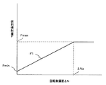
図3は、エンジンコントローラ13が燃料噴射量を演算するときに用いる燃料噴射量特性を示す図である。図中、横軸はエンジンコントロールダイヤル12が指示する目標回転数とエンジン回転数検出装置15によって検出されたエンジン11の実回転数との偏差ΔNであり、縦軸は燃料噴射量Fである。この燃料噴射量特性は、回転数偏差ΔNがゼロであるとき、燃料噴射量Fは最小Fminであり、回転数偏差ΔNが増大するにしたがって燃料噴射量Fは斜めの直線F1の特性に沿って直線比例的に増大するよう設定されている。また、回転数偏差ΔNがある所定の値ΔNaに達すると、燃料噴射量Fは最大Fmaxとなり、それ以上回転数偏差ΔNが増大したときは、燃料噴射量Fは最大Fmaxの一定値に保持される。通常のエンジン制御では、目標回転数毎に燃料噴射量特性を記憶しておき、エンジンコントロールダイヤル12が指示する目標回転数に応じて対応する燃料噴射量特性を選択し、そのとき演算した回転数偏差ΔNを燃料噴射量特性に参照して対応する燃料噴射量を求め、その燃料噴射量を目標値として電子ガバナ14に与え、エンジン11の各気筒に噴射される燃料噴射量を制御する。
FIG. 3 is a diagram showing a fuel injection amount characteristic used when the
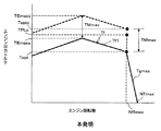
図4は、そのように燃料噴射量が制御されたときのエンジン11の出力トルク特性を示す図であり、エンジンコントロールダイヤル12が指示する目標回転数が最大であるときのものである。図中、横軸はエンジン回転数であり、縦軸はエンジン出力トルクである。エンジン11の出力トルク特性は、燃料噴射量が最大であるときの全負荷特性Tfと、図3に示した燃料噴射特性に基づいて燃料噴射量が調整されるレギュレーション特性Tgmaxとからなっている。全負荷特性Tfはエンジン11の特性によって定まるものであり、エンジン回転数が低下するにしたがってエンジン11の出力トルクが最大TEmaxeまで増加する左上がりの特性部分Tf1と、エンジン回転数が更に低下するにしたがってエンジン11の出力トルクが減少する左下がりの特性部分Tf2とからなっている。レギュレーション特性Tgmaxは、図3に示した燃料噴射特性に対応して、エンジン回転数が低下するにしたがってエンジン11の出力トルクが増大するドループ制御の特性となっている。
FIG. 4 is a diagram showing the output torque characteristics of the
すなわち、エンジン11に負荷が投入されていないときは燃料噴射量は最小Fminであり、このときのエンジン回転数はレギュレーション特性Tgmaxの直線と横軸との交点のNTmaxである。エンジン11の負荷トルク(油圧ポンプ21の吸収トルク)が増大し、目標回転数NTmaxと実回転数との偏差ΔNが増大するにしたがって燃料噴射量が増大し、それに伴ってエンジン11の出力トルクはレギュレーション特性Tgmaxの斜めの直線に沿って直線比例的に増大する。エンジン11の負荷トルクが更に増大し、回転数偏差ΔNが所定の値ΔNaに達すると燃料噴射量は最大となる(図3)。レギュレーション特性Tgmaxの直線と全負荷特性Tfとの交点は燃料噴射量が最大Fmaxとなり、エンジン11の出力馬力が最大となる点(後述)であり、このときの回転数(最大馬力回転数)NRmaxが定格回転数であり、エンジン11の出力トルクToptが定格トルクである。
That is, when the load is not applied to the
エンジンコントロールダイヤル12が最大目標回転数NTmaxよりも低い目標回転数NTx1,NTx2を指示するとき、エンジンコントローラ13は目標回転数NTx1,NTx2のそれぞれに対応した燃料噴射特性を選択して燃料噴射量を制御し、それに対応してレギュレーション特性は破線Tg1,Tg2と変化する。その結果、最大馬力回転数はNR1,NR2と低下する(後述)。
When the
本実施の形態では、エンジンコントロールダイヤル12が指示する目標回転数がエンジン11に負荷が投入されていないときの回転数NTmax,NTx1,NTx2であると定義したが、目標回転数は最大馬力回転数(エンジンコントロールダイヤル12が指示する目標回転数が最大であるときは定格回転数)NRmax,NR1,NR2であると定義してもよい。また、本実施の形態では、レギュレーション特性がドループ制御の特性である場合について説明したが、レギュレーション特性は、エンジン負荷の増加によらずエンジン回転数が一定に保たれるように燃料噴射量を調整するアイソクロナス制御の特性であってもよい(後述)。
In the present embodiment, the target rotational speed indicated by the
エンジン1の出力軸は大径ギヤ6aと小径ギヤ6bからなる動力分配器6を介して油圧系2と発電電動系3に連結されている。
The output shaft of the
油圧系2は、油圧ポンプ21及びパイロットポンプ22と、コントロールバルブ23と、複数の油圧アクチュエータ24a〜24hと、複数の操作装置25,26とを備えている。
The
油圧ポンプ21及びパイロットポンプ22はエンジン11の出力軸に動力分配器6を介して連結され、エンジン11により駆動される。油圧ポンプ21から吐出された圧油はコントロールバルブ23を介して複数の油圧アクチュエータ24a〜24hに供給され、それぞれの被駆動体を駆動する。油圧ポンプ21は可変容量型であり、押しのけ容積可変機構(例えば斜板)21aと、押しのけ容積可変機構21aの傾転位置を調整し、油圧ポンプの容量を制御するポンプレギュレータ27を備えている。
The
複数の油圧アクチュエータ24a〜24hは、左右の走行用油圧モータと、それ以外の油圧アクチュエータを含み、それ以外の油圧アクチュエータは、例えば、ブーム用油圧シリンダ、アーム用油圧シリンダ、バケット用油圧シリンダ、スイング用油圧シリンダ、ブレード用油圧シリンダを含む。
The plurality of
コントロールバルブ23は複数の油圧アクチュエータ24a〜24hに対応する複数のメインスプールを内蔵し、これらメインスプールは操作装置25,26から出力される油圧信号により切換操作される。操作装置25は左右の走行用の操作装置を代表したものであり、操作装置26は走行以外の操作装置を代表したものである。
The
発電電動系3は、発電・電動機31と、インバータ32と、バッテリ(蓄電装置)33と、バッテリコントローラ34と、操作パネル35とを備えている。
The
発電・電動機31はエンジン11の出力軸に動力分配器6を介して連結され、エンジン11に余剰トルクがあるときは、その余剰トルクによって駆動されて発電機として作動する。発電・電動機31が発生した電気エネルギーはインバータ32を介してバッテリ33に蓄電される。また、発電・電動機31は、バッテリ33の容量に対する蓄電量の比率(以下、充電率という)がアシスト駆動に必要な最小充電率(例えば30%)以上でありかつ油圧ポンプ21をアシスト駆動する必要があるときは、インバータ32を介してバッテリ33の電気エネルギーが供給され、電動機として作動する。バッテリコントローラ34はバッテリ33の蓄電量を監視し、操作パネル35はその蓄電量に係わる情報(蓄電情報)を表示する。
The generator /
制御系4は、走行速度切換スイッチ41と、トルク制御電磁弁44と、走行速度切替電磁弁45と、制御装置としての車体コントローラ46とを備え、車体コントローラ46は、走行速度切換スイッチ41、トルク制御電磁弁44及び走行速度切替電磁弁45と電気的に接続されている。また、車体コントローラ46は、インバータ32、バッテリコントローラ34、操作パネル35及びエンジンコントローラ13とも電気的に接続されている。車体コントローラ46は、走行速度切換スイッチ41の指示信号、エンジンコントローラ13のエンジン回転数情報(目標回転数及び検出した実回転数)、操作パネル35の操作信号及びバッテリコントローラ34の蓄電情報(充電率)を入力し、所定の演算処理を行い、インバータ32、トルク制御電磁弁44及び走行速度切替電磁弁45に制御信号を出力する。
The
図5は、ポンプレギュレータ27の構成の詳細を示す図である。 FIG. 5 is a diagram showing details of the configuration of the pump regulator 27.
ポンプレギュレータ27は、複数の操作装置25,26の操作量に基づく要求流量に応じた流量を吐出するよう油圧ポンプ21の押しのけ容積可変機構21aの傾転位置を制御する(したがって油圧ポンプ容量を制御する)LS制御部等の要求流量応答制御部と、油圧ポンプ21の最大吸収トルクを予め定められた値を超えないように油圧ポンプ21の押しのけ容積可変機構21aの最大傾転位置を制御する(したがって油圧ポンプの最大容量を制御する)トルク制御部とを有している。図5は、図示の簡略化のため、トルク制御部のみ図示している。また、動力分配器6は図示を省略している。
The pump regulator 27 controls the tilting position of the displacement
図5において、ポンプレギュレータ27は、油圧ポンプ21の押しのけ容積可変機構21aに作動的に連結された制御スプール27aと、この制御スプール27aに対して油圧ポンプ21の容量増加方向に作用する第1及び第の2つのバネ27b,27cと、スプール27aに対して油圧ポンプ21の容量減少方向に作用する第1及び第2受圧部27d,27eとを有している。第1受圧部27dには油圧ポンプ21の吐出圧力がパイロットライン27fを介して導入される。第1及び第2バネ27b,27cは油圧ポンプ21の最大吸収トルクを設定するものである。第1バネ27bは第2バネ27cよりも長く、制御スプール27aが図示の初期位置にあるときは第1バネ27bのみが制御スプール27aに接触して、制御スプール27aを図示右方向に付勢する。制御スプール27aが図示左方向にある程度移動すると第2バネ27cも制御スプール27aに接触して、第1及び第2バネ27b,27cの両方が制御スプール27aを図示右方向に付勢する。
In FIG. 5, the pump regulator 27 includes a
トルク制御電磁弁44は、車体コントローラ46から制御信号が出力されていないときは図示のOFF位置にあり、ポンプレギュレータ27の第2受圧部27eをタンクに連通させる。車体コントローラ46から制御信号が出力されると、トルク制御電磁弁44はON位置に切り換えられ、第2受圧部27eに制御圧力としてパイロットポンプ22の吐出圧力が導かれる。パイロットポンプ22の吐出圧力はパイロットリリーフ弁28により一定の値(例えば4Mpa)に保たれている。
The torque
図6は、ポンプレギュレータ27のトルク制御部の機能を示すポンプトルク特性図であり、横軸は油圧ポンプ21の吐出圧力を示し、縦軸は油圧ポンプ21の容量を示している。
FIG. 6 is a pump torque characteristic diagram showing the function of the torque control unit of the pump regulator 27, where the horizontal axis shows the discharge pressure of the
また、図6において、符号TP1及びTP2で示される2つの直線(実線)からなる折れ曲がり線は第1及び第2バネ27b,27cにより設定される最大吸収トルク特性である。直線TP1,TP2に接する符号TPLcで示される曲線は油圧ポンプ21の最大吸収トルクであり、これはトルク制御の制限トルクということもできる。油圧ポンプ21の最大吸収トルク(制限トルク)TPLcはエンジン11の定格トルクToptに発電・電動機31の最大トルクTMmaxを加算した定格システムトルクToptc(後述)よりも所定の余裕分だけ小さくなるように設定されている。また、油圧ポンプ21の最大吸収トルクTPLcはエンジン11の定格トルクToptより大きく、本実施の形態においては油圧ポンプ21の最大吸収トルクTPLcは更に最大トルクTEmaxe(後述)よりも大きい。
In FIG. 6, a bent line formed by two straight lines (solid lines) indicated by reference numerals TP1 and TP2 is the maximum absorption torque characteristic set by the first and
このような油圧ポンプ21の吸収トルクとエンジン11の出力トルクとの関係から分かるように、エンジン11は、定格トルクToptが油圧ポンプ21の最大吸収トルクTPLcよりも小さく、エンジン11の出力トルクだけでは油圧ポンプ21の最大吸収トルクTPLcを賄えない大きさにダウンサイジング(小型化)されている。また、本実施の形態においては、更にエンジン11は、定格トルクToptだけでなく最大トルクTEmaxeも油圧ポンプ21の最大吸収トルクTPLcよりも小さい大きさにダウンサイジングされている。なお、図中、Aは走行高速時の代表的な出力使用範囲、Bは走行低速時の代表的な出力使用範囲、Cは通常作業時の代表的な出力使用範囲を示しており、これらについては後述する。
As can be seen from the relationship between the absorption torque of the
ポンプレギュレータ27のトルク制御部は、油圧ポンプ21の吐出圧力に応じて油圧ポンプ21の押しのけ容積可変機構21aの最大傾転位置(したがって油圧ポンプ21の最大容量)を制限することで油圧ポンプ21の最大吸収トルクを制限するものである。油圧ポンプ21の吐出圧力の上昇時に吐出圧力が第1の値P1を超える前は、油圧ポンプ21の吐出圧力が導かれる受圧部27dの油圧力は第1バネ27bの付勢力より小さく、油圧ポンプ21の最大容量はqmaxに維持される。すなわち、油圧ポンプ21の容量は要求流量応答制御部の制御によりqmaxまで上昇させることができる。油圧ポンプ21の吐出圧力が更に上昇して第1の値P1を超えると、受圧部27dの油圧力は第1バネ27bの付勢力より大きくなり、制御スプール27aは図示左方向に移動して、油圧ポンプ21の最大容量は折れ曲げ線の直線TP1に沿って減少する。これにより要求流量応答制御部により制御される油圧ポンプ21の容量は直線TP1が規定する最大容量以下に制限され、油圧ポンプ21の吸収トルク(ポンプ吐出圧力と容量の積)は制限トルクTPLcを超えないように制御される。
The torque control unit of the pump regulator 27 limits the maximum tilt position of the
油圧ポンプ21の吐出圧力が更に上昇して第2の値P2を超えると、制御スプール27aは第2バネ27cに接触して、油圧ポンプ21の吐出圧力の上昇量に対する制御スプール27aの移動量の割合(油圧ポンプ21の容量の減少割合)は減少し、油圧ポンプ21の最大容量は直線TP1よりも傾きの小さい直線TP2に沿って減少する。この場合も、油圧ポンプ21の吸収トルクは制限トルクTPLcを超えないように制御される。油圧ポンプ21の吐出圧力がメインリリーフ弁29の設定圧力に達すると、それ以上油圧ポンプ21の吐出圧力の上昇は阻止される。
When the discharge pressure of the
トルク制御電磁弁44がON位置に切り換わると、第2受圧部27eに制御圧力が導かれ、制御スプール27aには第2受圧部27eの油圧力が第1及び第2バネ27b,27cの付勢力に対向して作用する。これにより第1及び第2バネ27b,27cによる最大吸収トルクの設定は、第2受圧部27eの油圧力の分だけ減少するよう調整され、最大吸収トルク特性は、矢印で示すように、実線の直線TP1,TP2からなる折れ曲げ線から一点鎖線の直線TP3,TP4からなる折れ曲げ線へとシフトする(減トルク量ΔTPd1)。その結果、油圧ポンプ21の吐出圧力の上昇時、油圧ポンプ21の最大容量は折れ曲げ線の一点鎖線の直線TP3,TP4に沿って減少する。このときの油圧ポンプ21の最大吸収トルク(ポンプ吐出圧力と最大容量の積)は直線TP1,TP2の最大吸収トルクTPLcから直線TP3,TP4に接する曲線のTPLd1へと小さくなり、エンジン11に余剰トルクTG(後述)が強制的に作り出される。本願明細書では、この制御を減トルク制御という。
When the torque
図7は、油圧系のコントロールバルブと複数の油圧アクチュエータのうち、左右の走行用油圧モータに係わる油圧回路部分を示す図である。図中、左右の走行用のメインスプールを符号23a,23bで示し、左右の走行用油圧モータを符号24a,24bで示している。左右の油圧モータ24a,24bはメインスプール23a,23bを介して油圧ポンプ21に接続されている。
FIG. 7 is a diagram showing a hydraulic circuit portion related to the left and right traveling hydraulic motors among the hydraulic control valve and the plurality of hydraulic actuators. In the drawing, the left and right traveling main spools are denoted by
左右の油圧モータ24a,24bはそれぞれ可変容量型であり、押しのけ容積可変機構(斜板)24a1,24b1と、押しのけ容積可変機構24a1,24b1をそれぞれ駆動する制御ピストン24a2,24b2とを備えている。制御ピストン24a2,24b2の一側には受圧部24a3,24b3が形成され、その反対側にはバネ24a4,24b4が配置されている。
The left and right
走行速度切替電磁弁45が図示のOFF位置にあるとき、制御ピストン24a2,24b2の受圧部24a3,24b3はタンクに連通しており、制御ピストン24a2,24b2はバネ24a4,24b4の力で押されて図示の位置にあって、押しのけ容積可変機構24a1,24b1は大傾転位置(大容量位置)に保持されている。走行速度切替電磁弁45がON位置に切り換えられると、制御ピストン24a2,24b2の受圧部24a3,24b3に制御圧力としてパイロットポンプ22の吐出圧力が導かれ、これにより制御ピストン24a2,24b2が作動して、押しのけ容積可変機構24a1,24b1は大傾転位置(大容量位置)から小傾転位置(小容量位置)へと切り換えられる。大傾転位置では油圧モータ24a,24bは低速回転が可能であり、走行低速に適した状態となり(低速大容量モード)、小傾転位置では油圧モータ24a,24bは高速回転が可能であり、走行高速に適した状態となる(高速小容量モード)。車体コントローラ46は走行速度切換スイッチ41の指示信号を入力し、走行速度切換スイッチ41が走行低速を指示しているときは何もせず、走行速度切替電磁弁45をOFF位置に保持し、走行速度切換スイッチ41が走行高速を指示しているときは走行速度切替電磁弁45に制御信号を出力し、走行速度切替電磁弁45をON位置に切り換える。
When the travel speed switching
次に、本発明の動作原理について説明する。 Next, the operation principle of the present invention will be described.
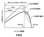
図8Aは、従来の一般的なミニショベルの油圧ポンプのPQ特性(馬力特性)と代表的な出力使用範囲との関係を示す図であり、横軸は油圧ポンプの吐出圧力を示し、縦軸は油圧ポンプの吐出流量を示している。図8Bは、同ミニショベルのエンジン出力馬力特性と代表的な出力使用範囲との関係を示す図であり、横軸はエンジン回転数を示し、縦軸はエンジンの出力馬力を示している。図8Cは、同ミニショベルのエンジンの出力トルク特性を示す図であり、横軸はエンジン回転数を示し、縦軸はエンジンの出力トルクを示している。図8A、図8B及び図8Cは、図4と同様、エンジンコントロールダイヤルが指示する目標回転数が最大NTmaxであるときのものである。 FIG. 8A is a diagram showing the relationship between the PQ characteristics (horsepower characteristics) of a conventional general mini excavator hydraulic pump and a typical output usage range, the horizontal axis shows the discharge pressure of the hydraulic pump, and the vertical axis Indicates the discharge flow rate of the hydraulic pump. FIG. 8B is a diagram showing the relationship between the engine output horsepower characteristics of the mini excavator and a typical output usage range, in which the horizontal axis indicates the engine speed and the vertical axis indicates the engine output horsepower. FIG. 8C is a graph showing the output torque characteristics of the engine of the mini-excavator, in which the horizontal axis indicates the engine speed and the vertical axis indicates the engine output torque. 8A, 8B, and 8C are the same as in FIG. 4 when the target rotational speed indicated by the engine control dial is the maximum NTmax.
まず、油圧ポンプのPQ特性について説明する。油圧ポンプのPQ特性とは、ある最大吸収トルク特性を持つ油圧ポンプをエンジンで駆動して回転させ、作業を行ったときに得られる油圧ポンプの出力馬力特性である。図8Aの油圧ポンプのPQ特性は、一例として、図6に示した最大吸収トルク特性を持つ油圧ポンプ21の場合のものであり、かつエンジン回転数が定格回転数NRmaxdにある場合のものである。定格回転数NRmaxdとは、図8Cのレギュレーション特性Tgmaxdと全負荷特性Tfdの交点におけるエンジン回転数であり、図8Bに示すように、最大目標回転数NTmaxに基づいて制御されているエンジンの出力馬力が最大となるときのエンジン回転数である。
First, the PQ characteristic of the hydraulic pump will be described. The PQ characteristic of the hydraulic pump is an output horsepower characteristic of the hydraulic pump obtained when a hydraulic pump having a certain maximum absorption torque characteristic is driven and rotated by the engine. The PQ characteristic of the hydraulic pump in FIG. 8A is, for example, that of the
一般的なミニショベルの作業状態として、走行高速時と走行低速時と通常作業時とを考える。図8A及び図8B中、Aは走行高速時の代表的な出力使用範囲、Bは走行低速時の代表的な出力使用範囲、Cは通常作業時の代表的な出力使用範囲を示している。走行高速とは、走行用の油圧モータ24a,24bが高速小容量モードにありかつ走行用の操作装置25が操作されて走行している状態をいい、走行低速とは、走行用の油圧モータ24a,24bが低速大容量モードにありかつ走行用の操作装置25が操作されて走行している状態をいう。通常作業とは、走行以外の操作装置26(特にフロント作業機104に係わる油圧アクチュエータ24c,24d,24e及び旋回モータのいずれかに係わる操作装置)が操作されて作業を行っている状態をいう。
As a general working state of a mini excavator, consider a traveling high speed, a traveling low speed, and a normal working state. 8A and 8B, A represents a typical output use range at a traveling high speed, B represents a typical output use range at a traveling low speed, and C represents a typical output use range during normal work. The traveling high speed means a state where the traveling
一般的なミニショベル(小型ショベル)においては、走行高速時Aはスピード(大流量)が必要であり、図8A及び図8Bに示すように走行高速時Aにおける油圧ポンプ21の出力は最も大きくなる。走行低速時B及び通常作業時Cにおいて油圧ポンプ21の出力は走行高速時Aよりも小さい。このことは、通常作業時に油圧ポンプの出力が最も大きくなる中型、大型の油圧ショベルの場合と大きな相違である。
In a general mini excavator (small excavator), a speed (a large flow rate) is required at a traveling high speed A, and the output of the
従来のミニショベルでは、図6に示した油圧ポンプ21の最大吸収トルク(トルク制御の制限トルク)TPLcは、図8Cに示すように、エンジンの定格トルクToptdよりも所定の余裕分だけ小さく設定されている。図8Aの符号HPLcは図6及び図8Cに示した油圧ポンプ21の最大吸収トルクTPLcに対応する油圧ポンプ21の最大吸収馬力を示しており、この油圧ポンプ21の最大吸収馬力HPLcもエンジンの最大馬力(定格馬力)HEoptdよりも所定の余裕分だけ小さくなるように設定されている。また、走行高速時は油圧ポンプ21の出力は最も大きくなるため、油圧ポンプ21の最大吸収馬力HPLcは、走行高速時Aの運転状態で油圧ポンプ21に要求される油圧馬力を賄うことができる大きさに設定されている。
In the conventional mini excavator, the maximum absorption torque (limit torque for torque control) TPLc of the
一方、ポンプレギュレータ27の最大吸収トルク特性(図6)は、第1及び第2の2つのバネ27b,27cによって実線の直線TP1,TP2からなる折れ曲げ線のように設定されるため、油圧ポンプ21のPQ特性も同様に符号HPで示すように折れ曲げ線形状となり、通常作業時ではエンジンの最大馬力(定格馬力)HEoptdに対して油圧ポンプ21の出力使用範囲CがPQ特性の折れ曲げ線の交点における凹み分Xa分だけXと大きく離れて、余裕がありすぎる状態となる。これは、エンジン出力馬力を有効に使用していないことを意味する。
On the other hand, the maximum absorption torque characteristic (FIG. 6) of the pump regulator 27 is set like a bent line formed by solid lines TP1 and TP2 by the first and
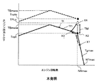
図9Aは、本実施の形態によるミニショベルの油圧ポンプのPQ特性(馬力特性)と代表的な出力使用範囲との関係を示す図であり、図9Bは、同ミニショベルのエンジン出力馬力特性と代表的な出力使用範囲との関係を示す図である。図9Cは、エンジン11と発電・電動機31とを組み合わせたハイブリッド駆動システムの出力トルク特性を示す図である。図9A、図9B及び図9Cは、図4と同様、エンジンコントロールダイヤルが指示する目標回転数が最大でNTmaxあるときのものである。
FIG. 9A is a diagram showing a relationship between the PQ characteristic (horsepower characteristic) of the hydraulic pump of the mini excavator according to the present embodiment and a typical output usage range, and FIG. 9B shows the engine output horsepower characteristic of the mini excavator and It is a figure which shows the relationship with a typical output usage range. FIG. 9C is a diagram illustrating output torque characteristics of a hybrid drive system in which the
本実施の形態では、エンジン11の最大馬力(定格馬力)HEoptを図8Bに示した従来の最大馬力(定格馬力)HEoptdよりも小さくし、油圧ポンプ21の馬力特性HPにおける最大吸収馬力HPLcを下回る設定とする。更に言えば、本実施の形態では、エンジン11の最大馬力(定格馬力)HEoptを、走行高速時A以外(走行低速時B及び通常作業時C)の運転状態で油圧ポンプ21に要求される油圧馬力の大部分を賄うことができ、走行高速時Aの運転状態で油圧ポンプ21に要求される油圧馬力を賄うことができない大きさに設定する。このことをエンジン11の出力トルクで言い換えると、エンジン11の定格トルクToptは、図6に示すように、走行高速時A以外(走行低速時B及び通常作業時C)の運転状態で油圧ポンプ21に要求される油圧トルクの大部分を賄うことができ、走行高速時Aの運転状態で油圧ポンプ21に要求される油圧トルクを賄うことができない大きさに設定されている。
In the present embodiment, the maximum horsepower (rated horsepower) HEopt of the
本実施の形態では、このようにダウンサイジングしたエンジン11を用い、エンジン回転数が定格回転数NRmax以下に低下したときにエンジン回転数が定格回転数NRxに維持されるよう発電・電動機31を電動機として作動させ出力アシスト制御を行い、エンジン回転数が定格回転数NRxより大きい(エンジン11に余剰トルクがある)ときに発電・電動機31を発電機として作動させる充電制御(第1充電制御)を行うものである。
In the present embodiment, using the
例えば、走行高速時Aにおいて、油圧ポンプ21の吸収トルクが最大吸収トルクTPLcまで増加し、エンジン11の回転数が定格回転数NRmaxを下回る場合には、バッテリ33により発電・電動機31を電動機として作動させ出力アシストを行う。図9CのToptcは図8Cに示す従来技術の定格トルクToptdに対応するものであり(例えばToptc=Toptd)、発電・電動機31の最大アシスト時の定格システムトルクToptc(エンジン定格トルクToptと電動機の最大トルクTMmaxの合計トルク)である。図9AのHEmaxcは、発電・電動機31の最大アシスト時のシステム出力馬力、すなわち定格システム馬力(エンジン定格馬力HEoptと電動機の最大馬力HMmaxの合計出力)である。
For example, if the absorption torque of the
通常作業時Cにおいては、油圧ポンプ21の出力をエンジン11の定格トルクToptの出力で賄えない場合のみ、バッテリ33により発電・電動機31を電動機として作動させ出力アシストを行い、それ以外の場合はエンジン11の出力のみで油圧ポンプ21を駆動する。また、バッテリ33の充電残量が少ないときは充電制御(第1充電制御)によりバッテリ33に電力を充電する。
In normal operation C, only when the output of the
このようにエンジン11の出力トルクを従来よりも小さくし、定格トルクTopt或いは最大トルクTEmaxeが油圧ポンプ21の最大吸収トルクTPLcを下回る大きさにしたため、エンジン11の出力トルクをフルに使用できるようになるとともに、エンジン11をダウンサイジング(小型化)することが可能となる。エンジン11をダウンサイジングすることにより低燃費化、エンジン11から排出される有害なガスの量の低減、及び騒音の低減が可能となる。また、排出ガス後処理装置の小型化或いは簡略化が可能となり、エンジン11のダウンサイジング化によるコスト低減と相まってエンジンの製作コストを低減することができ、機械全体の価格を下げることができる。また、エンジン11の最大トルクTEmaxeが油圧ポンプ21の最大吸収トルクTPLcよりも小さい大きさにまでエンジン11をダウンサイジングしたため、ミニショベルのような小型の作業機械にハイブリッド方式を採用する場合のレイアウト面の困難性を回避し、バッテリ33の設置スペースを確保することができ、ハイブリッド方式の採用が容易となる。
In this way, the output torque of the
また、本実施の形態では、作業機械が通常作業時Cの油圧ポンプ21の出力が走行高速時Aよりも小さいミニショベルのような小型の油圧ショベルであるため、エンジン11がダウンサイジングされていても、通常作業時Cの油圧ポンプ21の出力をエンジン11の定格トルクTopt以下の出力で賄える場合が多い。このような小型の作業機械において、エンジン回転数が定格回転数NRmax以下に低下したときに出力アシスト制御を行い、エンジン回転数が定格回転数NRxより大きいときに充電制御(第1充電制御)を行うことにより、出力アシスト制御の頻度が少なくなり、バッテリ33の消費電力が抑えられる。また、バッテリ33の充電制御の頻度を増加させ、バッテリ33の充電量を増加させることができる。その結果、ブーム下げ時或いは旋回制動時の回生エネルギーによってバッテリの消費電力を回収することができないミニショベルのような小型の建設機械において、旋回フレーム上の狭いスペースに搭載可能なサイズにバッテリ33が小型化されていても、バッテリ33の充電残量の早期の減少が抑えられ、バッテリ33の充電のために作業を中断する頻度を低減することができ、機体の稼動率を向上できる。
Further, in the present embodiment, the
また、本実施の形態では、第1出力アシスト制御と第1充電制御の切り換えを行うため、作業機械がミニショベルのような小型の作業機械でありかつバッテリ33が小型化されていてもバッテリ33の充電残量の早期の減少が抑えられる。しかし、小型の油圧ショベルでは、旋回電動モータを用いた場合の旋回制動時の回生エネルギーによってバッテリ33の消費電力を回収することが困難であるため、上記のように効率的にバッテリ33の充電制御を行ったとしても、バッテリの充電量が最小充電率以下に低下する事態が発生することは避けられず、その場合の対策を考慮する必要がある。
In the present embodiment, since the first output assist control and the first charge control are switched, the
本実施の形態では、バッテリの充電量が最小充電率以下に低下した場合は、エンジン回転数低下制御とポンプ減トルク制御を併用して第2充電制御を行う。これにより後述する如く、油圧ショベルの作業量の低下を抑えつつバッテリ33の急速充電を行うことが可能となる。その結果、エンジン11の小型化でバッテリ33の充電量が最小充電率以下に低下した場合でも、バッテリ33の充電中にある程度の作業を行うことができ、バッテリ充電中の機体の稼動効率の低下を抑えることができる。
In the present embodiment, when the charge amount of the battery decreases below the minimum charge rate, the second charge control is performed by using the engine speed reduction control and the pump torque reduction control together. As a result, as will be described later, the
〜制御〜
次に、図10を用いて上述した本発明の動作原理を実現する車体コントローラ46の制御機能について説明する。
~control~
Next, the control function of the
図10は、車体コントローラ46による制御を示すブロック図である。車体コントローラの制御は、走行制御部46aと、状態判定制御部46bと、ポンプ/エンジン制御部46c(第1制御部)と、発電・電動機/バッテリ制御部46d(第2制御部)とで構成されている。
FIG. 10 is a block diagram showing control by the
走行制御部46aは、走行速度切換スイッチ41からの入力信号に応じて走行速度切替電磁弁45のON/OFF切換信号を出力する。状態判定制御部46bは、エンジンコントローラ13から入力されるエンジンの目標回転数と実回転数、及びバッテリコントローラ34から入力されるバッテリ33の充電率に基づいて状態判定を行う。ポンプ/エンジン制御部46cは、状態判定制御部46bによる判定結果に応じて、トルク制御電磁弁44に対してON/OFF切換信号を出力し、エンジンコントローラ13に対してはエンジン回転数の低下指示を出力する。発電・電動機/バッテリ制御部46dは、状態判定制御部46bによる判定結果に応じて、インバータ32に対して制御信号を出力し、バッテリコントローラ34に対しては充電指示を出力する。
The traveling
図11は、車体コントローラ46の制御部46b〜46d(図10)による制御を示すフロー図である。図11において、フローを構成する各ステップには、それぞれを実行する制御部の符号を括弧書で付している。以下、各ステップについて順に説明する。
FIG. 11 is a flowchart showing control by the
まず、バッテリコントローラ34からの蓄電情報から取得したバッテリ33の充電率が最小充電率(SOC)よりも大きいか否かを判定する(ステップS90)。最小充電率とは発電・電動機31のアシスト駆動による作業の継続が不能となる充電率(例えば30%)である。ステップ90でYES(バッテリ充電率>30%)と判定された場合は、バッテリ充電率が第1閾値より小さいか否かを判定する(ステップS100)。第1閾値とは、バッテリの充電量が発電・電動機31の駆動は可能であるが、バッテリ充電制御により充電を行うことが必要な状態であるか否かを判定するための閾値であり、作業の継続が不能となる最小充電率(例えば30%)よりも高い値(例えば50%)に設定されている。ステップS100でYES(バッテリ充電率<50%)と判定された場合は、エンジンコントローラ13からのエンジン回転数情報から取得した現在のエンジン回転数(実回転数)が最大馬力回転数NRxより小さいか否かを判定する(ステップS110)。前述したように、エンジンコントロールダイヤル12が指示する目標回転数が最大NTmaxであるとき、最大馬力回転数は定格回転数NRmaxある。
First, it is determined whether or not the charging rate of the
ここで、最大馬力回転数について、図12を用いて詳しく説明する。図12は、目標回転数とエンジン出力馬力及び最大馬力回転数の関係を示す図である。図中の実線Emax,E1,E2及び破線Smax,S1,S2は、それぞれ目標回転数をNTmax,NT1,NT2に設定した場合のエンジン馬力特性及びシステム馬力特性を示している。目標回転数NTmax,NT1,NT2(以下、NTxという)に基づいて制御されているエンジン11の出力馬力は、それぞれ、エンジン回転数が最大馬力回転数NRmax,NR1,NR1(以下、NRxという)のときに最大となる。なお、最大目標回転数NTmaxに対応する最大馬力回転数NRmaxは、エンジン11の定格回転数と一致する。図12に示した目標回転数NTxと最大馬力回転数NRxとの対応関係を車体コントローラ46の記憶装置に予め記憶させておくことにより、エンジンコントロールダイヤル12による目標回転数の設定に応じて最大馬力回転数を変更することが可能となる。
Here, the maximum horsepower rotation speed will be described in detail with reference to FIG. FIG. 12 is a diagram illustrating the relationship between the target rotational speed, the engine output horsepower, and the maximum horsepower rotational speed. Solid lines Emax, E1, E2 and broken lines Smax, S1, S2 in the figure indicate the engine horsepower characteristics and system horsepower characteristics when the target rotational speed is set to NTmax, NT1, NT2, respectively. The output horsepower of the
図11に戻り、ステップS110でYES(エンジン回転数<最大馬力回転数NRx)と判定された場合は、発電・電動機31を電動機として作動させ(ステップS140A)、ステップS90に戻り、ステップS90以降の処理を繰り返し実行する。ステップS140Aで行われる出力アシスト制御によって、エンジン回転数は上昇して最大馬力回転数NRxに戻され、最大馬力回転数NRxに維持される。また、ハイブリッド駆動システムの出力トルクは従来と同じTPLcまで増加し(図9C参照)、システム出力馬力は従来と同じHPLcまで増加する。発電・電動機31を電動機として作動させる制御方法としては、例えば最大馬力回転数からエンジン回転数(実回転数)を差し引いた回転数偏差ΔNdを求め、この回転数偏差ΔNdが大きくなるにしたがって駆動トルクが増加するよう発電・電動機31を制御すればよい。
Returning to FIG. 11, when it is determined as YES (engine speed <maximum horsepower speed NRx) in step S110, the generator /
ステップS110でNO(エンジン回転数≧最大馬力回転数NRx)と判定された場合は、エンジン11の負荷トルク(油圧ポンプ21の吸収トルク)がエンジン11の定格トルクToptよりも小さく、エンジン11に余裕がある場合であり、この場合はエンジン11の余剰トルクによって発電・電動機31を駆動して発電・電動機31を発電機として作動させ(ステップS120)、バッテリ充電制御を行う(ステップS130)。これによりエンジン11の出力トルクは定格トルクToptまで増加し、エンジン回転数は最大馬力回転数NRxまで低下し、エンジン出力馬力は最大馬力まで増加する。さらに、エンジン11の余剰トルクによって発電機31が駆動され、発電機31で発電した電力がインバータ32を介してバッテリ33に蓄電される。発電・電動機31を発電機として作動させる制御方法としては、例えばエンジン回転数(実回転数)から最大馬力回転数を差し引いた回転数偏差ΔNcを求め、この回転数偏差ΔNcが大きくなるにしたがって発電トルクが増加するよう発電・電動機31を制御すればよい。
If NO (engine speed ≥ maximum horsepower speed NRx) is determined in step S110, the load torque of the engine 11 (absorbed torque of the hydraulic pump 21) is smaller than the rated torque Topt of the
ステップS130に続いて、バッテリ充電率が第2閾値より大きいか否かを判定する(ステップS150)。第2閾値とは、バッテリの充電が不要か否かを判定するための閾値であり、第1閾値よりも高い値(例えば70%)に設定されている。ステップS150でYES(バッテリ充電率>70%)と判定された場合は、処理を終了する。一方、ステップS150でNO(バッテリ充電率≦70%)と判定された場合は、ステップS100に戻り、ステップS100以降の処理を繰り返し実行する。 Following step S130, it is determined whether the battery charge rate is greater than a second threshold (step S150). The second threshold value is a threshold value for determining whether or not the battery needs to be charged, and is set to a value (for example, 70%) higher than the first threshold value. If it is determined as YES (battery charging rate> 70%) in step S150, the process is terminated. On the other hand, when it is determined NO (battery charge rate ≦ 70%) in step S150, the process returns to step S100, and the processes after step S100 are repeatedly executed.
ステップS100でNO(バッテリ充電率≦50%)と判定された場合は、バッテリ33の充電が不要であるとみなせる場合であり、この場合は、ステップS110と同様にエンジン回転数が最大馬力回転数NRxより低いか否かを判定する(ステップS160)。ステップS160でYES(エンジン回転数<最大馬力回転数NRx)と判定された場合は、発電・電動機31を電動機として作動させ(ステップS140B)、ステップS100に戻り、ステップS100以降の処理を繰り返し実行する。これにより、エンジン回転数は最大馬力回転数NRxに維持されるとともに、システム出力トルクは従来と同じTPLcまで増加し(図9C参照)、システム出力馬力は従来と同じHPLcまで増加する。一方、ステップS160でNO(エンジン回転数≧最大馬力回転数NRx)と判定された場合は、処理を終了する。
If NO (battery charge rate ≦ 50%) is determined in step S100, it can be considered that charging of the
ステップS90において、バッテリ33の充電率が最小充電率(例えば30%)以下になると、ステップS210に移行する。
In step S90, when the charging rate of the
ステップS210以下は急速充電制御の処理手順であり、エンジン回転数低下制御(ステップS210)とポンプ減トルク制御(ステップS220)を行った後、バッテリ33の充電制御(第2充電制御)(ステップS230,S240)を行う。 Step S210 and subsequent steps are processing procedures for rapid charge control. After performing engine speed reduction control (step S210) and pump torque reduction control (step S220), charge control (second charge control) of the battery 33 (step S230). , S240).
ステップS210のエンジン回転数低下制御では、エンジン11の最大目標回転数をNTmaxからNtcに低下させる制御を行う。この制御のため車体コントローラ46はエンジン回転数低下制御用の目標回転数NTcを予め記憶しておき、この目標回転数NTcをエンジンコントローラ13に出力する。エンジンコントローラ13は、エンジンコントロールダイヤル12が指示する目標回転数NTxとその目標回転数NTcの小さい方を選択して燃料噴射制御の目標回転数として設定し、この目標回転数に基づいて燃料噴射量を算出し、電子ガバナ14を制御する。これによりエンジン11の最大目標回転数はNTmaxからNtcに低下し、エンジン11の最大馬力回転数における出力トルクはToptからTopt1に増加する(図16B)。なお、エンジンコントロールダイヤル12が指示する目標回転数NTxを車体コントローラ46側で入力し、最大目標回転数の変更を車体コントローラ46で行ってもよい。
In the engine speed reduction control in step S210, control is performed to reduce the maximum target speed of the
ステップS220のポンプ減トルク制御では、車体コントローラ46は電磁弁44に制御信号を出力して油圧ポンプ21の最大吸収トルクをTPLcからTPLd1に減少させる制御を行う(図6及び図16A)。
In the pump torque reduction control in step S220, the
ステップS230,S240の充電制御では、以上のエンジン回転数低下制御とポンプ減トルク制御により強制的に作り出したエンジン11の余剰トルクを用いて発電・電動機31を発電機として作動させ、バッテリ11の急速充電を行う。
In the charge control in steps S230 and S240, the generator /
このようにステップS210〜S240において、バッテリ33(蓄電装置)の充電率が発電・電動機31のアシスト駆動による作業の継続が不能となる最小充電率以下に低下した場合は、エンジン11の目標回転数を低下させるエンジン回転数低下制御と油圧ポンプ21の最大吸収トルクを低下させる減トルク制御とを行うことによりエンジン11に強制的に余剰トルクを生成し、この余剰トルクを用いて発電・電動機31を発電機として作動させてバッテリ33を充電する第2充電制御を行う。
As described above, in steps S210 to S240, when the charging rate of the battery 33 (power storage device) has dropped below the minimum charging rate at which the continuation of the work by the assist drive of the generator /
ステップS240に続き、バッテリ33の充電率が予め設定した第3閾値より大きいか否かを判定する(ステップS250)。ここで第3閾値とは、バッテリ33の充電量が極めて不十分な状態を脱したことを示す充電率であり、最小充電率(例えば30%)より高い値(例えば40%)に設定されている。ステップS250でNO(バッテリ充電率≦第3閾値(40%))と判定された場合は、バッテリ充電率が第3閾値以上になるまでステップS210〜S240の処理を繰り返し実行する。ステップS210〜S250は、バッテリ33の充電量が極めて不十分な場合に実行される強制的なバッテリ充電制御(急速充電制御)である。
Following step S240, it is determined whether the charging rate of the
ステップS250でYES(バッテリ充電率>第3閾値(40%))と判定された場合ステップS100に移行し、上述した上述した出力アシスト制御(ステップS140A,S130B)或いは充電制御(ステップS120,S130 )を行う。 If YES in step S250 (battery charge rate> third threshold (40%)), the process proceeds to step S100, and the above-described output assist control (steps S140A and S130B) or charge control (steps S120 and S130) described above. I do.
〜動作〜
本実施の形態に係る駆動システムの動作を、図13A、図13B、図14A及び図14Bを用いて説明する。図13Aは、アシスト制御によるシステム出力トルクの変化を示す図であり、横軸はエンジン回転数を示し、縦軸は出力トルクを示している。図14Aは、アシスト制御によるシステム出力馬力の変化を示す図であり、横軸はエンジン回転数を示し、縦軸は出力馬力を示している。図13Bは、バッテリ充電制御によるシステム出力トルクの変化を示す図であり、横軸はエンジン回転数を示し、縦軸はシステム出力トルクを示している。図14Bは、バッテリ充電制御によるエンジン出力馬力の変化を示す図であり、横軸はエンジン回転数を示し、縦軸はエンジン出力馬力を示している。
~ Operation ~
The operation of the drive system according to the present embodiment will be described with reference to FIGS. 13A, 13B, 14A, and 14B. FIG. 13A is a diagram illustrating a change in system output torque by assist control, in which the horizontal axis indicates the engine speed and the vertical axis indicates the output torque. FIG. 14A is a diagram illustrating a change in system output horsepower by assist control, in which the horizontal axis indicates the engine speed and the vertical axis indicates the output horsepower. FIG. 13B is a diagram illustrating a change in system output torque due to battery charging control, in which the horizontal axis indicates the engine speed and the vertical axis indicates the system output torque. FIG. 14B is a diagram illustrating changes in engine output horsepower due to battery charging control, in which the horizontal axis indicates the engine speed and the vertical axis indicates the engine output horsepower.
図13Aにおいて、符号X1は、バッテリ充電率が50%以上(ステップS100の判定がNO)で充電制御を行っておらずかつエンジン回転数が定格回転数NRmax(NRx)以上で油圧ポンプ21の吸収トルク(負荷トルク)をエンジン11の出力トルクだけで賄っている(ステップS160の判定がNO)場合のエンジン11の動作点を示している。この状態から油圧ポンプ21の吸収トルクが最大吸収トルクTPLcまで増加するとき、エンジン11と発電・電動機31を組み合わせたハイブリッド駆動システムの動作点はX1→X2→X3→X4と変化する。
In FIG. 13A, symbol X1 indicates that the battery charge rate is 50% or more (determination in step S100 is NO), charge control is not being performed, and the engine speed is higher than the rated speed NRmax (NRx) and absorption by the
まず、エンジン11の負荷トルクが増加してエンジン回転数が定格回転数NRmaxまで低下すると、燃料噴射量は最大Fmax(図3)となり、エンジン11の出力トルクは定格トルクToptまで増加する(動作点X2)。更にエンジン11の回転数が低下すると発電・電動機31が電動機として作動し(ステップS160の判定がYES→ステップS140)、エンジン回転数が定格回転数NRmaxに維持されるよう制御される。また、システム出力トルクはエンジン11の定格トルクToptと発電・電動機31の出力トルクTMとの合計となる。このとき、アシスト制御の遅れのため、エンジン11の回転数は定格回転数NRmaxよりも一旦低下し(動作点X3)、発電・電動機31が作動し始めると、エンジン11の回転数は上昇し、定格回転数NRmaxへと戻される(動作点X4)。
First, when the load torque of the
図14Aにおいて、上述した出力トルクの変化に対応してエンジン出力馬力とシステム出力馬力の動作点もX1→X2→X3→X4と変化する。符号HE1,HS1は、動作点X1におけるエンジン出力馬力及びシステム出力馬力を示しており、両者は一致している。一方、符号HE2,HS2は、それぞれ動作点X2,X4におけるエンジン出力馬力及びシステム出力馬力を示している。動作点X4では、エンジン出力馬力HE2は最大馬力となり、システム出力馬力HS2は、エンジン出力馬力HE2(最大馬力)と電動機31の出力馬力HMとの合計出力となる。
In FIG. 14A, the operating points of the engine output horsepower and the system output horsepower also change from X1 → X2 → X3 → X4 in response to the change in the output torque described above. Symbols HE1 and HS1 indicate the engine output horsepower and the system output horsepower at the operating point X1, and they coincide with each other. On the other hand, symbols HE2 and HS2 indicate the engine output horsepower and the system output horsepower at the operating points X2 and X4, respectively. At the operating point X4, the engine output horsepower HE2 is the maximum horsepower, and the system output horsepower HS2 is the total output of the engine output horsepower HE2 (maximum horsepower) and the output horsepower HM of the
図13Bにおいて、符号Y1は、図13Aの動作点X1と同様、バッテリ充電率が50%以上(ステップS100の判定がNO)で充電制御を行っておらずかつエンジン回転数が定格回転数NRmax(NRx)以上で油圧ポンプ21の吸収トルク(負荷トルク)をエンジン11の出力トルクだけで賄っている(ステップS160の判定がNO)場合のエンジン11の動作点を示している。この状態からバッテリ充電率が50%よりも小さくなると(ステップS100の判定がYES)、エンジン11の動作点はY1→Y2と変化する。すなわち、このときはエンジン回転数が定格回転数NRmax(NRx)以上で余剰トルクTGnがあるため、このエンジン11の余剰トルクTGnによって発電・電動機31を発電機として作動させ、バッテリ33を充電する充電制御を行う(動作点Y2)。
In FIG. 13B, as with the operating point X1 in FIG. 13A, the symbol Y1 indicates that the battery charging rate is 50% or more (determination in step S100 is NO), the charging control is not performed, and the engine speed is the rated speed NRmax ( The operating point of the
図14Bにおいて、符号HE3は、動作点Y1でのエンジン出力馬力を示している。一方、符号HE4は、動作点Y2でバッテリ充電制御を行った場合のエンジン出力馬力を示している。このとき、エンジン出力馬力HE4は最大馬力となり、HE3とHE4との差分HGnが充電馬力となる。 In FIG. 14B, the symbol HE3 indicates the engine output horsepower at the operating point Y1. On the other hand, the symbol HE4 indicates the engine output horsepower when the battery charging control is performed at the operating point Y2. At this time, the engine output horsepower HE4 becomes the maximum horsepower, and the difference HGn between HE3 and HE4 becomes the charging horsepower.
バッテリ33の充電率が最小充電率(SOC)以下に低下した場合の第2充電制御時の動作を、図15A〜図16Bを用いて説明する。
The operation at the time of the second charge control when the charge rate of the
図15Aは、比較例として、ポンプ減トルク制御だけで急速充電制御を行った場合の油圧ポンプ21の最大吸収トルクの変化(減トルク量)を示す図であり、図15Bはポンプ減トルク制御だけで急速充電制御を行う場合の減トルク量と、そのときのバッテリ33の急速充電の発電トルクとして使用されるエンジン11の余剰トルクと作業に使用可能な最大トルクの配分を示す図である。
FIG. 15A is a diagram showing a change (amount of torque reduction) in the maximum absorption torque of the
図15Aにおいて、電磁弁44に制御信号を出力することで油圧ポンプ21の最大吸収トルクがTPLcからTPLd2に減少し、このときの減トルク量は太線矢印のΔTPd2である。
In FIG. 15A, the maximum absorption torque of the
図15Bにおいて、TGはバッテリ33の急速充電の発電トルクとして使用されるエンジン11の余剰トルクを示し、TPaはエンジン回転数低下制御を行わなかった場合の作業に使用可能な最大トルク量を示している。
In FIG. 15B, TG indicates the surplus torque of the
比較例では、エンジン回転数低下制御を行わないため最大目標回転数はNRmaxのままである。この場合、エンジン11の最大馬力回転数(定格回転数)はNRmaxであり、そのときのエンジン11の出力トルクはToptとなる。減トルク制御後の最大吸収トルクTPLd2はエンジン11の出力トルクToptから発電トルクとして使用される余剰トルクTGを差し引いたトルク量に合わせる必要があり、その最大吸収トルクTPLd2(ToptからTGを差し引いたTPa)が作業に使用可能な最大トルク量となる。
In the comparative example, since the engine speed reduction control is not performed, the maximum target speed remains NRmax. In this case, the maximum horsepower rotation speed (rated rotation speed) of the
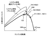
図16Aは、本実施の形態においてエンジン回転数低下制御とポンプ減トルク制御によって急速充電制御を行う場合の油圧ポンプ21の最大吸収トルクの変化(減トルク量)を示す図であり、図6にエンジン11のエンジン回転数低下制御後の最大馬力回転数における出力トルクTopt1を追記した図である。図16Bは、本実施の形態において必要となる減トルク量と、そのときのエンジン11の余剰トルクと作業に使用可能な最大トルクの配分を示す図である。
FIG. 16A is a diagram showing a change (amount of torque reduction) of the maximum absorption torque of the
本実施の形態では、エンジン回転数低下制御を行うため、最大目標回転数はNTcへと低下し、エンジン11の最大馬力回転数における出力トルクはToptからTopt1に増加する。このとき、減トルク制御後の最大吸収トルクTPLd1はエンジン11の増加した出力トルクTopt1から発電トルクとして使用される余剰トルクTGを差し引いたトルク量に合わせればよく、その最大吸収トルクTPLd1(Topt1からTGを差し引いたTPb)が作業に使用可能な最大トルク量となる。この最大作業トルク量TPb(減トルク制御後の最大吸収トルクTPLd1)はエンジン11の最大馬力回転数における出力トルクがToptからTopt1に増加した分だけ多くなる。
In the present embodiment, since engine speed reduction control is performed, the maximum target speed decreases to NTc, and the output torque at the maximum horsepower speed of the
このようにポンプ減トルク制御だけで急速充電制御を行う比較例では、最大吸収トルクの低下量である減トルク量ΔTPd2が大きくなるため、急速充電中は、油圧ポンプの出力が大きく低下し、例えば掘削作業などの高負荷トルクを要する作業に支障を来たす恐れがある。これに対し、本実施の形態では、エンジン回転数低下制御によってエンジン出力トルクがToptからTopt1に増加し、その分減トルク量ΔTPd1が少なくなるため、油圧ポンプ22の最大吸収トルクの低下量が比較例よりも少なくなり、最大作業トルク量TPbが比較例よりも大きくなり、急速充電中に作業を行う場合の作業量の低下を抑えることができる。
Thus, in the comparative example in which the quick charge control is performed only by the pump reduction torque control, the reduction torque amount ΔTPd2 that is the reduction amount of the maximum absorption torque is increased. Therefore, during the quick charge, the output of the hydraulic pump is greatly reduced. There is a risk of hindering work requiring high load torque such as excavation work. On the other hand, in the present embodiment, the engine output torque is increased from Topt to Top1 by the engine speed reduction control, and the decrease torque amount ΔTPd1 is reduced accordingly, so the reduction amount of the maximum absorption torque of the
〜効果〜
以上のように本実施の形態においては、出力アシストによってエンジン11の要求トルクを抑えることでエンジン11の小型化が可能となり、燃費の向上、排ガス特性の改善及び騒音の低減を図ることができる。
~effect~
As described above, in the present embodiment, it is possible to reduce the size of the
また、バッテリ33の充電率が最小充電率以下に低下した場合に、エンジン回転数を低下させるエンジン回転数低下制御を行うことにより、エンジン11の全負荷特性部分Tf1上の最大馬力回転数NRcにおけるエンジン出力トルクTopt1が増加する。これにより減トルク制御のみを行って余剰トルクを発生させる場合と比較して減トルク制御による油圧ポンプ21の最大吸収トルクの低下量が抑えられ、油圧ポンプ21の出力低下(油圧ショベルの作業量の低下)を抑えつつバッテリ33の急速充電を行うことが可能となる。これによりバッテリ33の充電中にもある程度の作業を行うことを可能とし、機体の稼動効率の低下を抑えることができる。
Further, when the charging rate of the
また、上述したように、ミニショベルのような小型の油圧ショベルにおいては、通常作業時Cの油圧ポンプ21の出力が走行高速時Aよりも小さいため、定格トルクTopt或いは最大トルクTEmaxeが油圧ポンプ21の最大吸収トルクTPLcを下回る大きさにダウンサイジングしたエンジン11であっても、通常作業時Cの油圧ポンプ21の出力をエンジン11の定格トルクTopt以下の出力で賄える場合が多い。このような小型の油圧ショベルにおいて、エンジン回転数が最大馬力回転数である定格回転数NRmax以下に低下したときに出力アシスト制御を行い、エンジン回転数が最大馬力回転数である定格回転数NRxより大きい(エンジン11に余剰トルクがある)ときに充電制御を行うことにより、出力アシスト制御の頻度が少なくなり、バッテリ33の消費電力が抑えられる。また、作業効率を低下させることなくバッテリ33の充電制御の頻度を増加させ、バッテリ33の充電量を増加させることができる。これによりブーム下げ時或いは旋回制動時の回生エネルギーによってバッテリの消費電力を回収することができないミニショベルのような小型の建設機械において、旋回フレーム上の狭いスペースに搭載可能なサイズにバッテリ33が小型化されていても、バッテリ33の充電残量の早期の減少が抑えられ、バッテリ33の充電率が最小充電率以下に低下する頻度、すなわち急速充電を行う頻度を低減できる。これによりバッテリ33の充電のために作業を中断する頻度を低減し作業効率の低下を抑え、機体の稼動率を向上させることができる。
Further, as described above, in a small hydraulic excavator such as a mini excavator, the output of the
〜変形例〜
本実施の形態では、エンジン回転数と最大馬力回転数NRx(目標回転数が最大NTmaxの場合は定格回転数NRmax)との大小判定結果に基づいてアシスト制御とバッテリ充電制御とを切り替えることとしたが、判定に用いる最大馬力回転数NRxにはマージンを持たせても良い。すなわち、エンジン回転数のハンチング等を考慮した所定のマージンΔNを設定し、エンジン回転数が最大馬力回転数NRx+ΔNより大きくなったときにバッテリ充電制御を行い、エンジン回転数が最大馬力回転数NRx−ΔNより小さくなったときにアシスト制御を行っても良い。これにより、エンジン回転数が最大馬力回転数NRx付近にあるときの発電・電動機31の制御を安定化させることができる。
~ Modification ~
In the present embodiment, the assist control and the battery charge control are switched based on the magnitude determination result between the engine speed and the maximum horsepower speed NRx (or the rated speed NRmax when the target speed is the maximum NTmax). However, the maximum horsepower rotation speed NRx used for determination may have a margin. That is, a predetermined margin ΔN is set in consideration of hunting of the engine speed, etc., and when the engine speed becomes greater than the maximum horsepower speed NRx + ΔN, the battery charging control is performed, and the engine speed is set to the maximum horsepower speed NRx−. Assist control may be performed when it becomes smaller than ΔN. Thereby, the control of the generator /
また、本実施の形態では、電子ガバナ14の制御にエンジン負荷の増加に応じてエンジン回転数を低下させつつ燃料噴射量を増加させるドループ制御を採用した場合を例に説明したが、本発明はこれに限られず、エンジン負荷の増加によらずエンジン回転数が一定に保たれるように燃料噴射量を調整するアイソクロナス制御を採用することも可能である。
Further, in the present embodiment, the case where the droop control for increasing the fuel injection amount while decreasing the engine speed according to the increase of the engine load has been described as an example for the control of the
図17Aは、アイソクロナス制御を採用した場合のエンジン回転数とエンジン出力トルクとの関係を示す図であり、図17Bは、アイソクロナス制御を採用した場合のエンジン回転数とエンジン出力馬力との関係を示す図である。 FIG. 17A is a diagram showing the relationship between the engine speed and the engine output torque when the isochronous control is adopted, and FIG. 17B shows the relationship between the engine speed and the engine output horsepower when the isochronous control is adopted. FIG.
図17Aにおいて、出力トルクが定格トルクToptより小さい(エンジン11に余剰トルクがある)ときは、符号TEaで示すようにエンジン回転数は目標回転数NTx(=最大馬力回転数NRx)に保たれるように制御される。回転数偏差出力トルクが定格トルクToptより大きくなると、符号TEbで示すように出力エンジン回転数は最大馬力回転数NRxより小さくなる。一方、図17Bにおいては、出力トルクが定格トルクToptより小さい(エンジン11に余剰トルクがある)ときは、符号HEaで示すようにエンジン回転数は最大馬力回転数NRxに保たれ、出力トルクが定格トルクToptより大きくなると、符号HEbに示すようにエンジン回転数は最大馬力回転数NRxより小さくなり、出力馬力は最大馬力より小さくなる。エンジン回転数を目標回転数NTx(=最大馬力回転数NRx)に保つ制御(アイソクロナス制御)は、例えば実回転数>NRxであれば燃料噴射を停止し、実回転数<NRxであれば燃料噴射を行うというように、最大馬力回転数NRxを基準として燃料噴射をON,OFF制御することにより実現することができる。
In FIG. 17A, when the output torque is smaller than the rated torque Topt (the
このように、アイソクロナス制御では、エンジン11に余剰トルクがあるときのエンジン回転数の変化がドループ制御と相違するものの、エンジン回転数が最大馬力回転数NRxより小さいか否かによって出力アシストの要否が判定可能である。従って、アイソクロナス制御を採用した場合も本発明は適用可能である。
As described above, in the isochronous control, although the change in the engine speed when the
また、本実施の形態では、油圧ポンプ21及びパイロットポンプ22と発電・電動機31とを動力分配器6を介してエンジン11の出力軸に連結する構成としたが、本発明はこれに限られず、例えばエンジン11の出力軸に直列に連結する構成であっても良い。
In the present embodiment, the
1 エンジン系
2 油圧系
3 発電電動系
4 制御系
6 動力分配器
11 エンジン
12 エンジンコントロールダイヤル
13 エンジンコントローラ
14 電子ガバナ
15 エンジン回転数検出装置
21 油圧ポンプ
21a 押しのけ容積可変機構
22 パイロットポンプ
23 コントロールバルブ
23a,23b 走行用のメインスプール
24a,24b 走行用の油圧モータ
24c〜24h その他の油圧アクチュエータ
24a1,24b1 押しのけ容積可変機構(斜板)
24a2,24b2 制御ピストン
24a3,24b3 受圧部
24a4,24b4 バネ
25 走行用の操作装置
26 走行以外の操作装置
27 ポンプレギュレータ
27a 制御スプール
27b,27c 第1バネ及び第2バネ
27d,27e 第1受圧部及び第2受圧部
27f パイロットライン
27g 制御油路
29 メインリリーフ弁
31 発電・電動機
32 インバータ
33 バッテリ(蓄電装置)
34 バッテリコントローラ
35 操作パネル
41 走行速度切換スイッチ
42 走行の操作パイロット圧センサ
43 走行以外の操作パイロット圧センサ
44 トルク制御電磁弁
45 走行速度切替電磁弁
46 車体コントローラ
46a 走行制御部
46b 状態判定制御部
46c ポンプ/エンジン制御部(第1制御部)
46d 発電・電動機/バッテリ制御部(第2制御部)
101 下部走行体
102 上部旋回体
103 スイングポスト
104 フロント作業機
105 トラックフレーム
106 排土用のブレード
107 旋回台
108 キャビン(運転室)
111 ブーム
112 アーム
113 バケット
DESCRIPTION OF
24a2, 24b2 Control pistons 24a3, 24b3 Pressure receiving portions 24a4, 24b4
34
46d Power generation / motor / battery control unit (second control unit)
DESCRIPTION OF
111
Claims (3)
このエンジンによって駆動される油圧ポンプと、
この油圧ポンプから吐出される圧油によって駆動される複数の油圧アクチュエータと、
前記エンジンの目標回転数を指示するエンジン回転数指示装置と、
前記エンジンの実回転数を検出するエンジン回転数検出装置と、
前記エンジンの負荷トルクが増加するにしたがって前記エンジンの出力トルクが増加するよう燃料噴射量を制御するガバナ装置と、
前記エンジンに連結された発電・電動機と、
前記発電・電動機との間で電力を授受する蓄電装置と、
前記蓄電装置からの電力を前記発電・電動機に供給することで前記発電・電動機を電動機として作動させて出力アシストを行い、前記エンジンにより前記発電・電動機を回転駆動することで前記発電・電動機を発電機として作動させて前記蓄電装置を充電する制御装置とを備え、
前記エンジンは、前記ガバナ装置の燃料噴射量が最大であるときの全負荷特性と、前記ガバナ装置の燃料噴射量が最大に増加するまでのレギュレーション特性とを含む出力トルク特性を有し、前記全負荷特性は、前記エンジン回転数が定格回転数から所定回転数に低下するにしたがって前記エンジンの出力トルクが増加し、前記所定回転数で前記エンジンの出力トルクが最大となる第1特性部分と、前記エンジン回転数が前記所定回転数から低回するにしたがって前記エンジン出力トルクが減少する第2特性部分とを有し、
前記制御装置は、前記蓄電装置の充電率が前記発電・電動機のアシスト駆動による作業の継続が不能となる最小充電率以下に低下した場合に、前記エンジンの目標回転数を低下させるエンジン回転数低下制御と前記油圧ポンプの最大吸収トルクを低下させる減トルク制御とを行い、このエンジン回転数低下制御と減トルク制御によって前記エンジンに生じた余剰トルクを用いて前記発電・電動機を発電機として作動させて前記蓄電装置を充電する充電制御を行うことを特徴とするハイブリッド式作業機械。 Engine,
A hydraulic pump driven by this engine;
A plurality of hydraulic actuators driven by pressure oil discharged from the hydraulic pump;
An engine speed indicating device for instructing the target engine speed;
An engine speed detector for detecting the actual engine speed;
A governor device for controlling the fuel injection amount so that the output torque of the engine increases as the load torque of the engine increases;
A generator / motor coupled to the engine;
A power storage device that exchanges power with the generator / motor;
Supplying electric power from the power storage device to the generator / motor to operate the generator / motor as a motor to provide output assistance, and rotating the generator / motor by the engine to generate the generator / motor. A control device that operates as a machine and charges the power storage device,
The engine has an output torque characteristic including a full load characteristic when the fuel injection amount of the governor device is maximum and a regulation characteristic until the fuel injection amount of the governor device increases to the maximum, The load characteristic includes a first characteristic portion in which the output torque of the engine increases as the engine speed decreases from a rated speed to a predetermined speed, and the engine output torque becomes maximum at the predetermined speed; A second characteristic portion in which the engine output torque decreases as the engine speed decreases from the predetermined speed;
The control device reduces the engine speed when the charge rate of the power storage device falls below a minimum charge rate at which the operation by the assist drive of the generator / motor cannot be continued. Control and reduction torque control for reducing the maximum absorption torque of the hydraulic pump, and using the surplus torque generated in the engine by the engine speed reduction control and reduction torque control, the generator / motor is operated as a generator. And a charge control for charging the power storage device.
前記エンジンは、前記エンジン回転数が定格回転数にあるときのエンジン出力トルクである前記エンジンの定格トルクが前記油圧ポンプの最大吸収トルクよりも小さく、前記エンジンの出力トルクだけでは前記油圧ポンプの最大吸収トルクを賄えない大きさにダウンサイジングされていることを特徴とするハイブリッド式作業機械。 The hybrid work machine according to claim 1,
In the engine, the rated torque of the engine, which is the engine output torque when the engine speed is at the rated speed, is smaller than the maximum absorption torque of the hydraulic pump, and the maximum output of the hydraulic pump is determined only by the output torque of the engine. A hybrid work machine that is downsized to a size that does not cover the absorption torque.
前記エンジンは、前記エンジンの最大トルクが前記油圧ポンプの最大吸収トルクよりも小さく、前記エンジンの出力トルクだけでは前記油圧ポンプの最大吸収トルクを賄えない大きさにダウンサイジングされていることを特徴とするハイブリッド式作業機械。 The hybrid work machine according to claim 1,
The engine is downsized so that the maximum torque of the engine is smaller than the maximum absorption torque of the hydraulic pump and the maximum absorption torque of the hydraulic pump cannot be covered only by the output torque of the engine. Hybrid work machine.
Priority Applications (6)
| Application Number | Priority Date | Filing Date | Title |
|---|---|---|---|
| JP2015040727A JP6232007B2 (en) | 2015-03-02 | 2015-03-02 | Hybrid work machine |
| CN201580044833.0A CN107075837B (en) | 2015-03-02 | 2015-11-25 | Hybrid work machines |
| EP15884018.1A EP3266942B1 (en) | 2015-03-02 | 2015-11-25 | Hybrid work machine |
| US15/506,192 US10315508B2 (en) | 2015-03-02 | 2015-11-25 | Hybrid work machine |
| KR1020177004629A KR101897933B1 (en) | 2015-03-02 | 2015-11-25 | Hybrid work machine |
| PCT/JP2015/083130 WO2016139852A1 (en) | 2015-03-02 | 2015-11-25 | Hybrid work machine |
Applications Claiming Priority (1)
| Application Number | Priority Date | Filing Date | Title |
|---|---|---|---|
| JP2015040727A JP6232007B2 (en) | 2015-03-02 | 2015-03-02 | Hybrid work machine |
Publications (2)
| Publication Number | Publication Date |
|---|---|
| JP2016160662A JP2016160662A (en) | 2016-09-05 |
| JP6232007B2 true JP6232007B2 (en) | 2017-11-15 |
Family
ID=56844337
Family Applications (1)
| Application Number | Title | Priority Date | Filing Date |
|---|---|---|---|
| JP2015040727A Active JP6232007B2 (en) | 2015-03-02 | 2015-03-02 | Hybrid work machine |
Country Status (6)
| Country | Link |
|---|---|
| US (1) | US10315508B2 (en) |
| EP (1) | EP3266942B1 (en) |
| JP (1) | JP6232007B2 (en) |
| KR (1) | KR101897933B1 (en) |
| CN (1) | CN107075837B (en) |
| WO (1) | WO2016139852A1 (en) |
Families Citing this family (17)
| Publication number | Priority date | Publication date | Assignee | Title |
|---|---|---|---|---|
| CN105008625B (en) * | 2013-06-26 | 2017-04-12 | 日立建机株式会社 | Hybrid work machine |
| CN109070872B (en) * | 2016-09-16 | 2021-07-02 | 株式会社日立建机Tierra | Hybrid work machines |
| WO2017188193A1 (en) * | 2017-04-24 | 2017-11-02 | 株式会社小松製作所 | Control system and work machine |
| KR102304853B1 (en) * | 2017-07-31 | 2021-09-27 | 현대자동차주식회사 | Hybrid vehicle and method of controlling electric motor of the same |
| JP6769936B2 (en) * | 2017-08-31 | 2020-10-14 | 日立建機株式会社 | Hybrid work machine |
| US10780772B2 (en) * | 2018-10-23 | 2020-09-22 | Ge Global Sourcing Llc | Vehicle engine assist system |
| CN109630298B (en) * | 2018-12-12 | 2021-05-07 | 三一汽车制造有限公司 | Control method and control system of power system and engineering machinery |
| JP6955524B2 (en) * | 2019-03-26 | 2021-10-27 | 株式会社日立建機ティエラ | Battery-powered work machine |
| EP4596860A3 (en) * | 2019-06-28 | 2025-10-08 | Kubota Corporation | Working machine |
| JP7086898B2 (en) * | 2019-06-28 | 2022-06-20 | 株式会社クボタ | Working machine |
| JP7226220B2 (en) * | 2019-09-20 | 2023-02-21 | トヨタ自動車株式会社 | Hybrid vehicle control device |
| CN110901414B (en) * | 2019-12-16 | 2021-06-22 | 潍柴动力股份有限公司 | Vehicle torque control method, device and device |
| US12442339B2 (en) * | 2021-08-02 | 2025-10-14 | Transportation Ip Holdings, Llc | Electric drive system for a vehicle |
| CN114919561A (en) * | 2022-05-31 | 2022-08-19 | 湖南道依茨动力有限公司 | Vehicle control method and device, readable storage medium, electronic device and vehicle |
| CN115434819B (en) * | 2022-08-12 | 2024-04-12 | 中联重科股份有限公司 | Method, device, electronic equipment and engineering machinery for controlling power matching |
| DE102023122615A1 (en) * | 2023-08-23 | 2025-02-27 | Schwing Gmbh | Drive system for a mobile construction machine and method for driving it |
| KR20260023028A (en) * | 2023-09-26 | 2026-02-20 | 가부시키가이샤 히다치 겡키 티에라 | Electric construction machinery |
Family Cites Families (24)
| Publication number | Priority date | Publication date | Assignee | Title |
|---|---|---|---|---|
| JP3383754B2 (en) * | 1997-09-29 | 2003-03-04 | 日立建機株式会社 | Hydraulic construction machine hydraulic pump torque control device |
| JP4512283B2 (en) | 2001-03-12 | 2010-07-28 | 株式会社小松製作所 | Hybrid construction machine |
| JP4179465B2 (en) * | 2002-07-31 | 2008-11-12 | 株式会社小松製作所 | Construction machinery |
| JP3941951B2 (en) * | 2003-09-08 | 2007-07-11 | 株式会社小松製作所 | Drive control device for hybrid work machine |
| JP2007177719A (en) * | 2005-12-28 | 2007-07-12 | Hitachi Constr Mach Co Ltd | Engine and pump torque control device for hydraulic construction machine |
| WO2007139177A1 (en) * | 2006-06-01 | 2007-12-06 | Hitachi Construction Machinery Co., Ltd. | Exhaust gas purifier of construction machine |
| JP2008255699A (en) * | 2007-04-06 | 2008-10-23 | Caterpillar Japan Ltd | Control device for hybrid work machine |
| JP5156312B2 (en) * | 2007-09-19 | 2013-03-06 | 株式会社小松製作所 | Engine control device |
| JP2010265708A (en) * | 2009-05-18 | 2010-11-25 | Hitachi Constr Mach Co Ltd | Battery-driven work machine |
| JP3156582U (en) * | 2009-10-23 | 2010-01-07 | 株式会社豊田自動織機 | Hybrid industrial vehicle |
| JP5227981B2 (en) * | 2010-01-22 | 2013-07-03 | 日立建機株式会社 | Hybrid work machine |
| JP5226734B2 (en) * | 2010-05-20 | 2013-07-03 | 株式会社小松製作所 | Hybrid construction machinery |
| JP5228000B2 (en) | 2010-05-26 | 2013-07-03 | 日立建機株式会社 | Hybrid construction machine |
| EP2628860B1 (en) * | 2010-10-15 | 2019-07-03 | Hitachi Construction Machinery Co., Ltd. | Hybrid construction machine |
| JP5356423B2 (en) * | 2011-01-21 | 2013-12-04 | 日立建機株式会社 | Construction machine having a rotating body |
| JP5356436B2 (en) * | 2011-03-01 | 2013-12-04 | 日立建機株式会社 | Construction machine control equipment |
| JP5341134B2 (en) * | 2011-05-25 | 2013-11-13 | 日立建機株式会社 | Hydraulic work machine |
| EP2770119B1 (en) * | 2011-10-19 | 2021-09-22 | Hitachi Construction Machinery Co., Ltd. | Hybrid-driven hydraulic work machine |
| JP5916763B2 (en) * | 2012-01-05 | 2016-05-11 | 日立建機株式会社 | Construction machine control equipment |
| JP5952901B2 (en) * | 2012-05-14 | 2016-07-13 | 日立建機株式会社 | Hybrid construction machine |
| JP5913592B2 (en) * | 2012-06-22 | 2016-04-27 | 日立建機株式会社 | Construction machinery |
| JP6126625B2 (en) * | 2012-12-03 | 2017-05-10 | 日立建機株式会社 | Work machine |
| JP2016104927A (en) * | 2013-03-13 | 2016-06-09 | 日立建機株式会社 | Hybrid work vehicle |
| JP6091444B2 (en) * | 2014-02-03 | 2017-03-08 | 日立建機株式会社 | Hybrid construction machinery |
-
2015
- 2015-03-02 JP JP2015040727A patent/JP6232007B2/en active Active
- 2015-11-25 EP EP15884018.1A patent/EP3266942B1/en active Active
- 2015-11-25 CN CN201580044833.0A patent/CN107075837B/en active Active
- 2015-11-25 US US15/506,192 patent/US10315508B2/en active Active
- 2015-11-25 WO PCT/JP2015/083130 patent/WO2016139852A1/en not_active Ceased
- 2015-11-25 KR KR1020177004629A patent/KR101897933B1/en active Active
Also Published As
| Publication number | Publication date |
|---|---|
| KR101897933B1 (en) | 2018-09-12 |
| WO2016139852A1 (en) | 2016-09-09 |
| CN107075837A (en) | 2017-08-18 |
| US10315508B2 (en) | 2019-06-11 |
| JP2016160662A (en) | 2016-09-05 |
| EP3266942B1 (en) | 2020-05-20 |
| EP3266942A4 (en) | 2018-10-10 |
| US20170274755A1 (en) | 2017-09-28 |
| EP3266942A1 (en) | 2018-01-10 |
| KR20170034407A (en) | 2017-03-28 |
| CN107075837B (en) | 2020-02-18 |
Similar Documents
| Publication | Publication Date | Title |
|---|---|---|
| JP6232007B2 (en) | Hybrid work machine | |
| JP6211985B2 (en) | Hybrid work machine | |
| JP5227981B2 (en) | Hybrid work machine | |
| JP6226898B2 (en) | Hybrid work machine | |
| KR101391104B1 (en) | Construction machine and control method of construction machine | |
| JP5203434B2 (en) | Hybrid construction machinery | |
| JP6592187B2 (en) | Hybrid construction machinery | |
| KR101804433B1 (en) | Construction machine | |
| JP5858818B2 (en) | Construction machinery | |
| KR101952984B1 (en) | Hybrid construction machine and method for controlling same | |
| JP6539462B2 (en) | Hybrid work machine | |
| JP6258886B2 (en) | Hybrid work machine | |
| CN101297106A (en) | Engine control device, engine and hydraulic pump control device, and engine, hydraulic pump and generator-motor control device | |
| JP5997195B2 (en) | Hybrid work machine | |
| JP6009388B2 (en) | Work machine |
Legal Events
| Date | Code | Title | Description |
|---|---|---|---|
| A621 | Written request for application examination |
Free format text: JAPANESE INTERMEDIATE CODE: A621 Effective date: 20161107 |
|
| A711 | Notification of change in applicant |
Free format text: JAPANESE INTERMEDIATE CODE: A711 Effective date: 20170220 |
|
| TRDD | Decision of grant or rejection written | ||
| A01 | Written decision to grant a patent or to grant a registration (utility model) |
Free format text: JAPANESE INTERMEDIATE CODE: A01 Effective date: 20171003 |
|
| A61 | First payment of annual fees (during grant procedure) |
Free format text: JAPANESE INTERMEDIATE CODE: A61 Effective date: 20171020 |
|
| R150 | Certificate of patent or registration of utility model |
Ref document number: 6232007 Country of ref document: JP Free format text: JAPANESE INTERMEDIATE CODE: R150 |