EP2022624A1 - Powder compression molding machine and apparatus for continuous production of powder compression molded item using the machine - Google Patents
Powder compression molding machine and apparatus for continuous production of powder compression molded item using the machine Download PDFInfo
- Publication number
- EP2022624A1 EP2022624A1 EP07743356A EP07743356A EP2022624A1 EP 2022624 A1 EP2022624 A1 EP 2022624A1 EP 07743356 A EP07743356 A EP 07743356A EP 07743356 A EP07743356 A EP 07743356A EP 2022624 A1 EP2022624 A1 EP 2022624A1
- Authority
- EP
- European Patent Office
- Prior art keywords
- compact
- molding
- powder
- compacts
- slide plate
- Prior art date
- Legal status (The legal status is an assumption and is not a legal conclusion. Google has not performed a legal analysis and makes no representation as to the accuracy of the status listed.)
- Granted
Links
Images







Classifications
-
- B—PERFORMING OPERATIONS; TRANSPORTING
- B30—PRESSES
- B30B—PRESSES IN GENERAL
- B30B11/00—Presses specially adapted for forming shaped articles from material in particulate or plastic state, e.g. briquetting presses, tabletting presses
- B30B11/02—Presses specially adapted for forming shaped articles from material in particulate or plastic state, e.g. briquetting presses, tabletting presses using a ram exerting pressure on the material in a moulding space
- B30B11/14—Presses specially adapted for forming shaped articles from material in particulate or plastic state, e.g. briquetting presses, tabletting presses using a ram exerting pressure on the material in a moulding space co-operating with moulds on a movable carrier other than a turntable or a rotating drum
-
- B—PERFORMING OPERATIONS; TRANSPORTING
- B30—PRESSES
- B30B—PRESSES IN GENERAL
- B30B11/00—Presses specially adapted for forming shaped articles from material in particulate or plastic state, e.g. briquetting presses, tabletting presses
-
- B—PERFORMING OPERATIONS; TRANSPORTING
- B30—PRESSES
- B30B—PRESSES IN GENERAL
- B30B11/00—Presses specially adapted for forming shaped articles from material in particulate or plastic state, e.g. briquetting presses, tabletting presses
- B30B11/02—Presses specially adapted for forming shaped articles from material in particulate or plastic state, e.g. briquetting presses, tabletting presses using a ram exerting pressure on the material in a moulding space
-
- A—HUMAN NECESSITIES
- A61—MEDICAL OR VETERINARY SCIENCE; HYGIENE
- A61J—CONTAINERS SPECIALLY ADAPTED FOR MEDICAL OR PHARMACEUTICAL PURPOSES; DEVICES OR METHODS SPECIALLY ADAPTED FOR BRINGING PHARMACEUTICAL PRODUCTS INTO PARTICULAR PHYSICAL OR ADMINISTERING FORMS; DEVICES FOR ADMINISTERING FOOD OR MEDICINES ORALLY; BABY COMFORTERS; DEVICES FOR RECEIVING SPITTLE
- A61J3/00—Devices or methods specially adapted for bringing pharmaceutical products into particular physical or administering forms
- A61J3/10—Devices or methods specially adapted for bringing pharmaceutical products into particular physical or administering forms into the form of compressed tablets
Definitions
- the present invention relates generally to a powder compression molding machine which compressively molds powder into solids each having a desired dimension and shape and a powder compact continuous fabrication system using the machine. More specifically, the invention relates to a powder compression molding machine that can satisfactorily molds and collect compacts without crumblingness even when e.g. milk powder or the like is compressively molded into solids with large voids at a low compression force and that can mold compacts having sufficient voids and dissolving easily in water or the like while retaining their shapes without damage, and a powder compact continuous fabrication system using the machine.
- Solid milk is proposed which is compressively molded from a predetermined amount of powder milk so as to enable preparation of desired milk that is easily portable and eliminates measurement at the time of going out (Patent Document 1: WO2006/004190 ).
- a rotary tableting machine used for fabricating tablet medicines and the like are disclosed as a molding machine for compressively molding the solid milk (Patent Document 2: Japanese Patent Laid-open No. Hei 6-218028 , Patent Document 3: Japanese Patent Laid-open No. 2000-95674 , etc.)
- Such tableting machines are used for compressively molding tablet medicines, tablet-like foods, bath agents, agrichemical, and other medical agents and suitably configured to firmly compress and mold powder into relatively hard compacts. Thus, they are not suitable for compressively molding the solid milk mentioned above.
- porosity means the ratio of void volume to the bulk volume of powder (see, Edited by Koichiro Miyajima, "Development of Drug Medicine", Vol. 15, Hirokawa Publishing Company, page 240, 1989 ).
- the tableting machines mentioned above perform compression molding at a lower compression force, the molding speed must be reduced because compacts may be damaged at the time of being discharged and collected from the molding machine after compressively molded. This significantly reduces fabrication efficiency.
- the tableting machines do not essentially aim to perform compression molding at such a low compression force, it is extremely difficult to adjust porosity. That is to say, it is difficult to stably mold solid milk having a porosity of as large as 30% or more.
- These tableting machines fabricate compacts as below. A lower punch is inserted from below into a hole-like die perforated upward and downward and molding powder is poured in the die and is tamped down with upper and lower punches.
- the present invention has been made and it is an object of the present invention to provide a powder compression molding machine that can compressively molds powder such as powder milk into a state having high porosity at a low compression force, that can achieve satisfactory fabrication efficiency without disadvantage such as crumblingness of compacts at the time of collection, and that can efficiently fabricate compacts such as solid milk having high porosity and satisfactory shape-retaining performance, and a powder compact continuous fabrication system using this machine.
- the present invention provides a powder compression molding machine including: a machine main body having a compression molding zone and two compact discharge zones formed on both sides of the compression molding zone; a slide plate provided in the machine main body so as to be slidable in a horizontal direction; a first molding die section provided in the slide plate to include a plurality of arrayed through-die holes; a second molding die section including a plurality of through-die holes arrayed in the same manner as the first molding die section and juxtaposed to the first molding die section in the slide direction on the slide plate; an upper punch body having a plurality of upper punches arrayed to correspond to the through-die holes and disposed above the slide plate so as to be movable upward and downward in the compression molding zone; two compact discharger each having a plurality of discharge pins disposed to correspond to the through-die holes and disposed above the slide plate so as to be movable upward and downward in the two compact discharge zones; a lower punch body having a plurality of lower punches arraye
- the slide plate is slid to one of slide limits in which the first molding die section is located at the compression molding zone and the second molding die section is located at one of the compact discharge zones and to the other of the slide limits in which the second molding die section is located at the compression molding zone and the first molding die section is located at the other of the compact discharge zones.
- the lower punches of the lower punch body enter the through-hole die holes of the first or second molding die section to form the bottom walls of the through-die holes
- molding powder is poured into the through-die holes by the powder supply mechanism section
- the upper punches of the upper punch body enter the through-die holes, the molding powder is compressively molded by and between the upper punches and the lower punches.
- the discharge pins of the compact discharger enter the through-die holes of the second molding die section to press out downwardly the compacts from the through-die holes, the compacts being collected by the compact collection mechanism section.
- the discharge pins of the compact discharger enter the through-die holes of the first molding die section to press out downwardly the compacts from the through-die holes, the compacts been collected by the compact collection mechanism section.
- the powder compression molding by the powder compression molding machine of the present invention is performed in the following manner: At first, in the state where the slide plate is located at the one slide limit, the first molding die section of the slide plate is located at the compression molding zone, the lower punches of the lower punch body enter from below the through-die holes of the first molding die section to form the bottom walls in the through-die. In this sate, the powder supply mechanism section pours molding powder into the through-die holes. The upper punches of the upper punch body enters the through-die holes. The molding powder is compressively molded by and between the upper punches and lower punches. At this time, the second molding die section of the slide plate is located at the one compact discharge zone in which compacts are discharged in the same operation as the compact discharge operation of the first molding die section.
- the upper punches of the upper punch body and the lower punches of the lower punch body are withdrawn from the through-die holes.
- the slide plate is slid to the other slide limit and the first molding die section in which the compacts are retained in the through-die holes is moved to the other compact discharge zone.
- the discharge pins of the compact discharger enter from above the through-die holes of the first molding die section to press out downwardly the compacts from the through-die holes.
- Such compacts are received by the compact collection mechanism section.
- the second molding die section located at the one compact discharge zone is moved to the compression molding zone, where the powder compression molding is performed by the same operation described above.
- the slide plate is again moved to the one slide limit and in the compression molding zone the powder compression molding is performed in the first molding die section.
- the second molding die section is moved to the one compact discharge zone and similarly to the above the compacts are discharged by the discharge pins of the compact discharger and collected by the compact collection mechanism section.
- the molding operation is alternately repeated in the first and second molding die sections in the compression molding zone.
- the compact discharge operation from the second molding die section in the one compact discharge zone and the compact discharge operation from the first molding die section in the other discharge zone are alternately repeated.
- a plurality of the powder compacts is fabricated continuously.
- the powder compression molding machine of the present invention is configured such that the plurality of lower punches of the lower punch body and the plurality of upper punches of the upper punch body are allowed to enter the plurality of through-die holes provided in the first and second molding die sections of the slide plate, thus causing the upper and lower punches to compressively mold molding powder in the through-die holes. Therefore, even when the upper and lower punches are used to compressively mold powder at a low compression force for providing compacts having high porosity, a plurality of compacts can be molded at a time.
- the two molding sections, the first and second molding die sections are provided so that the compression molding operation is performed in one of the molding die section while compact discharge operation is performed in the other of the molding die section.
- the powder compression molding machine of the invention can efficiently mold compacts having high porosity without a reduction in throughput.
- the powder compression molding machine of the present invention configured such that the compacts retained in the through-die holes are pressed out downwardly by the discharge pins and discharged to the downside of the slide plate formed with the through-die holes.
- the compacts are received by the compact collecting means including the trays or the like.
- the compacts can be satisfactorily discharged and collected without application of a large load. Even compacts that are compressively molded by a low compression force and have high porosity can be discharged and collected without being damaged.
- the powder compression molding machine of the present invention is configured to mold a plurality of compacts at a time. Therefore, if exhibiting the same throughput as the conventional rotary tableting machine, the molding machine of the invention can perform compression molding at a relatively slow speed and at a low compression force, which can provide compacts having relatively high porosity. Further, the molding machine of the invention can be set such that compression molding may be performed by operating both the upper and lower punches without reducing the throughput.
- the present invention provides a powder compact continuous fabrication system including: two of the powder compression molding machines juxtaposed to each other; a first conveyor that passes through one of compact discharge zones included in each molding machine; and a second conveyor that passes through the other of the compact discharge zones included each molding machine.
- One of the molding machines alternately puts compacts on collection trays transferred by both the conveyors and discharges the compacts and the other of the molding machines alternately puts compacts on collection trays which are transferred by both the conveyors and on which compacts have not yet been put, and discharges the compacts.
- This continuous fabrication system molds powder compacts by using the two powder compression molding machines of the invention described above and efficiently supplies them to the two conveyor lines including of the first and second conveyors. That is to say, the powder compression molding machine of the invention is configured to include the compact discharge zones at two respective portions as described above so that compacts are alternately discharged from the two compact discharge zones. Then, two of the powder compression molding machines are juxtaposed to each other. The first conveyor for transferring the collection tray is disposed to pass through one of the compact discharge zones of each molding machine. Similarly, the second conveyor is disposed to pass through the other of the compact discharge zones of each molding machine. Each of the powder compression molding machines alternately discharges and supplies compacts to the respective collection trays on the first and second conveyors. Thus, the compacts are efficiently discharged and supplied to both the first and second conveyors in a non-intermittent or continuous manner for fabrication.
- the powder compact continuous fabrication system can significantly efficiently and continuously fabricates compacts that are compressively molded at a low compression force and have high porosity.
- the powder compression molding machine of the present invention can satisfactorily mold and collect compacts even when e.g. powder milk or the like is compressively molded into relatively large solids having high porosity at a low compression force, and additionally provide compacts that have sufficient high porosity and are dissolvable in water or the like. Further the powder compact continuous fabrication system composed of the molding machines can significantly efficiently and continuously fabricate the compacts described above.
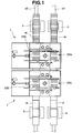
- Fig. 1 illustrates a powder compact continuous fabrication system composed of powder compression molding machines 1, 1 according to the present invention.
- This system allows two conveyor lines including of a first conveyor a1 and a second conveyor a2 to transfer respective collection trays d for collecting compacts and allows powder compacts compressively molded by the powder compression molding machines 1, 1 to be discharge and collected on the respective collection trays d for transport.
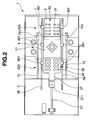
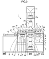
- the powder compression molding machine 1 includes a machine main body 2, a slide plate 3, an upper punch body 4, compact dischargers 5a, 5b, and a lower punch 6.
- the machine main body 2 has a compression molding zone 21 where powder is compressively molded and two compact discharge zones 22a, 22b.
- the slide plate 3 is disposed on the machine main body 2 so as to be slidable horizontally.
- the upper punch body 4 is disposed above the slide plate 3 in the compression molding zone 21 so as to be movable upward and downward.
- the compact dischargers 5a and 5b are disposed above the slide plate 3 in the respective compact discharge zones 22a and 22b so as to be movable upward and downward.
- the lower punch 6 is disposed below the slide plate 3 in the compression molding zone 21 so as to be movable upward and downward.
- the slide plate 3 is supported by slide rails 36, 36 installed on the machine main body 2 so as to be slidable horizontally via a plurality of sliders 361.
- a first molding die section 32 and a second molding die section 33 are provided in the slide-wise middle portion of the slide plate 3.
- the first molding die section 32 is formed with a large number of (16 in the embodiment) through-die holes 31 which perforate upward and downward and are arranged in an arrayed manner.
- the second molding die section 33 is formed with a large number of (16 in the embodiment) through-die holes 31 which are arranged at one end in the slide direction in an arrayed manner.
- a punch insertion section 35 is formed in the other end in the slide direction. In the punch insertion section 35, a plurality of (16 in the embodiment) circular through-holes 34 each slightly larger than the through-die holes 31 are arrayed in the same manner as the first and second molding die sections 32, 33.
- the slide plate 3 is formed with a tongue-like projection 37 at the central portion of the other end thereof.
- An internal thread body 371 secured to the tip of the projection 37 is threadedly engaged with a drive screw 23 provided on the machine main body 2.
- the drive screw 23 is rotated normally and reversely by a drive source not shown to cause the slide plate 3 to move horizontally in a reciprocative slide manner.
- the machine main body 2 is provided with a discharge guide plate 38 which is disposed closely below the slide plate 3 in the one compact discharge zone 22a.
- the discharge guide plate 38 is formed with a large number of (16 in the embodiment) compact passing holes 381 each of which are slightly larger than the through-die holes 31 and which are arrayed in the same manner as the first and second molding die sections 32, 33.
- a discharge guide plate 38 is disposed also in the other compact discharge zone 22b.
- the upper punch body 4 is disposed above the slide plate 3 in the compression molding zone 21 so as to be movable upward and downward.
- the upper punch body 4 is formed with a large number of (16 in the embodiment) upper punches 41 extending downward therefrom on the lower surface of a thick plate-like main body.
- the upper punches 41 are each formed with a square block-like compression part 411 (see Figs. 7 to 10 ) at the tip thereof.
- the upper punches 41 are arrayed in the same manner as the through-die holes 31 constituting the first and second molding die sections 32, 33 of the slide plate 3 so as to extend downward.
- the thick plate-like main body is provided with a spring which releases pressure applied to the upper punches when the pressure exceeds a predetermined level.
- the compact dischargers 5a and 5b are disposed above the slide plate 3 in the compact discharge zones 22a and 22b, respectively, so as to be movable upward and downward.
- the compact dischargers 5a, 5b are provided with a large number of (16 in the embodiment) discharge pins 51 extending downward on the lower surface of a thick plate-like main body.
- the discharge pins 51 are each formed with a square block-like depressing part 511 (see Figs. 11 to 14 ).
- the discharge pins 51 extend downward and are arrayed in the same manner as the through-die holes 31 constituting the first and second molding die sections 32, 33 of the slide plate 3.
- the compact dischargers 5a, 5b and the upper punch body 4 are attached to the same moving body 24a so as to integrally move upward and downward.
- the compact dischargers 5a, 5b are disposed so as to more project downward than the upper punch body 4 and designed to move more downward than the upper punch body 4.
- the moving body 24a attached with the compact dischargers 5a, 5b and with the upper punch body 4 is suspended by a hydraulic cylinder 25a as shown in Fig. 3 and is driven thereby to move upward and downward.
- the hydraulic cylinder 25a is suspended by a jack 26a, which can vertically adjust the position of the moving body 24a moved upward and downward by the hydraulic cylinder 25a.
- the amount of ingress of the upper punch 41 into the through-die holes 31 can be adjusted.
- the lower punch body 6 is disposed below the slide plate 3 in the compression molding zone 21 so as to be movable upward and downward.
- the lower punch body 6 is provided with a large number of lower punches 61 which are formed on the upper surface of a thick plate-like body so as to extend upright.
- the lower punches 61 are each formed with a square block-like compression part 611 at the tip thereof (see Figs. 7 to 10 ).
- the lower punches 61 extend upright and are arrayed in the same manner as the through-die holes 31 constituting the first and second molding die sections 32, 33 of the slide plate 3.
- the lower punch body 6 is attached to a moving body 24b as shown in Figs. 3 and 4 .
- the moving body 24b is supported by a first hydraulic cylinder 25b, which is further supported by a second hydraulic cylinder 25c.
- the second hydraulic cylinder 25c moves the lower punch body 6 together with the first hydraulic cylinder 25b upward and downward, thereby allowing the lower punches 61 to form bottom walls in the respective associated through-die holes 31.
- the first hydraulic cylinder 25b allows the lower punches 61 to move in the respective associated through-die holes 31 for compression molding. Note that this operation is detailed later.
- the second hydraulic cylinder 25c is supported by a jack 26b, which can further vertically adjust the position of the lower punches 61 moved upward and downward by the first and second hydraulic cylinders 25b, 25c.
- a jack 26b which can further vertically adjust the position of the lower punches 61 moved upward and downward by the first and second hydraulic cylinders 25b, 25c.
- a powder supply funnel 7 is disposed in the compression molding zone 21 so as to be close to the upper surface of the slide plate 3.
- This funnel 7 is an almost square box-like member having an opening lower end surface, in which a square frame-like opening portion 72 is joined to the lower end of an inverse four-sided pyramid-like funnel main body 71 as shown in Fig. 15 .
- powder supply pipes 73, 73 are mounted to both ends of the upper surface of the funnel main body 71.
- the powder supply pipes 73, 73 are connected to corresponding hoppers 74, 74 (see Figs. 3 and 4 ) mounted to upper portion of the machine main body 2.
- a pair of partition plates 721, 721 are provided inside the powder supply funnel 7 to extend upright at its central portion so as to correspond to the array of the through-die holes 31 of the slide plate 3.
- the funnel 7 is internally partitioned into left and right supply sections.
- Baffle plates 722, 722 are respectively provided to extend obliquely from the respective centers of the left and right supply sections to the respective central portions of the powder supply pipes 73, 73 located at both ends of the upper surface of the funnel main body.
- the powder supply pipes 73, 73 are connected to the corresponding hoppers 74, 74 via flexible pipes 741 (see Figs. 7 , 8 and 10 ).
- the powder supply funnel 7, hoppers 74, 74 and flexible pipes 741 constitute a powder supply mechanism section.
- the powder supply funnel 7 is supported via sliders 751, 751 by guide bars 75, 75 attached to the machine main body 2 as shown in Figs. 5 and 6 .
- the funnel 7 is reciprocated along the guide bars 75, 75 by a drive source not shown with its lower end opening surface brought into close to the upper surface of the slide plate 3. In this way, molding powder is poured in the through-die holes 31 of the first and second molding die sections 32, 33 located in the compression molding zone 21.
- the travel range of the powder supply funnel 7 is a range where the funnel 7 traverses the first or second molding die section 32, 33 of the slide plate 3 in the compression molding zone 21. As shown in Fig. 9 , the funnel 7 is located between the upper punch body 4 and the one compact discharger 5a in the one movement limit.
- Spaces 27, 27 each opening laterally are provided below the slide plate 3 at respective positions corresponding to the compact discharge zones 22a, 22b of the machine main body 2 as shown in Fig. 3 .
- the first and second conveyors a1, a2 pass through the corresponding spaces 27, 27.
- a pair of lifting arms (collection tray lifting devices) 8, 8 are disposed in each of the spaces 27, 27 so as to put a corresponding one of the conveyors a1, a2 therebetween.
- the lifting arms 8, 8 can temporarily lift a collection tray d put on each of the conveyors al, a2 and return it onto the corresponding one.
- the lifting arms 8, 8 and conveyors a1, a2 constitute a compact collection mechanism section.
- each of the first and second conveyors a1, a2 transfers the collection tray d through intermittent rotation.
- the operation of the powder compression molding machine is next described with reference to Figs. 5 to 14 .
- the slide plate 3 is located at the one slide limit as shown in Fig. 5
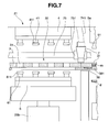
- the first molding die section 32 provided in the intermediate portion of the slide plate 3 is located in the compression molding zone 21 as shown in Figs. 5 and 7 .
- the second molding die section 33 provided at one end portion of the slide plate 3 is located in the one compact discharge zone 22a as shown in Figs. 5 and 11 .
- compacts m molded by the previous molding operation are retained in all the through-die holes 31 of the second molding die section 33.
- the lower punch body 6 is lifted to a desired height by being driven by the second hydraulic cylinder 25c (see Figs. 3 and 4 ) as shown in Fig. 8 .
- the compression parts 611 of the lower punches 61 enter from below the through-die holes 31 of the first molding die section 32 to form bottom walls in the through-die holes 31.
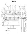
- the powder supply funnel 7 pours molding powder p in the through-die holes 31 while reciprocating along the upper surface of the slide plate 3 (see arrows in Fig. 8 ).
- the collection tray d put on the conveyor a1 is lifted by the lifting arms 8, 8 in the one compact discharge zone 22a as shown in Fig. 12 to come into close to the lower surface of the discharge guide plate 38 in the compact discharge zone 22a.
- the upper punch body 4 is moved downward by being driven by the hydraulic cylinders 25a (see Figs. 3 and 4 ) in the compression molding zone 21 while the compression parts 411 of the upper punches 41 enter the through-die holes 31 to press the molding powders p in the through-die holes 31.
- the lower punch body 6 is lifted by being driven by the first hydraulic cylinder 25b while the compression parts 611 of the lower punches 61 press the molding powder p.
- the molding powder p is compressively molded between both the compression parts 411, 611 of the upper and lower punches 41, 61.
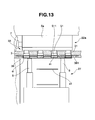
- the one compact discharger 5a moves downward integrally with the upper punch body 4 in the one compact discharge zone 22a so that the depressing parts 511 of the discharge pins 51 enters the through-die holes 31 of the second molding die section 33 from above as shown in Fig. 13 .
- the depressing parts 511 push out the compacts m in the through-die holes 31 downwardly and put them on the collection plate d through the compact passing holes 31 of the discharge guide plate 38.
- the upper punch body 4 and the one compact discharger 5a move downward integrally with the other compact discharger 5b in the other compact discharge zone 22b (see Figs. 2 , 3 and 5 ). Since the punch insertion section 35 of the slide plate 3 is located in the other compact discharge zone 22b as shown in Fig. 5 , the discharge pins 51 of the compact discharger 5b are inserted into the circular through-holes 34 of the punch insertion section 35 although not shown particularly in the figure.
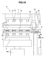
- the upper punch body 4 is moved upward by being driven by the hydraulic cylinder 25a (referred to as Figs. 3 and 4 ) as shown in Fig. 10
- the lower punch body 6 is moved downward by being driven by the first and second hydraulic cylinders 25b, 25c. Consequently, both the compression parts 411, 611 of the upper and lower punches 41, 61 withdraw from the through-die holes 31 so that the compacts m are retainably left in the through-die holes 31.
- the lifting arms 8, 8 move downward so that the collection tray d on which the compacts m put is placed on the conveyor a1 again as shown in Fig. 14 . Then, the conveyor a1 turns to discharge the compacts m from the powder compression molding machine 1.
- the slide plate 3 is driven by the drive screw 23 to move to the other slide limit as shown in Fig. 6 .
- the second molding die section 33 where the through-die holes 31 are empty after the compacts m have been discharged in the one compact discharge zone 22a is moved to the compression molding zone 21.
- the first molding die section 32 where the compacts m molded in the compression molding zone 21 are retained in the through-die holes 31 is moved to the other compact discharge zone 22b.
- the powder compacts m are molded in the through-die holes 31 of the second molding die section 33 in the same operation as the molding operation described with Figs. 7 to 10 .
- the compacts m in the through-die holes 31 of the first molding die section 32 are discharged in the same manner as the molding operation described with Figs. 11 to 14 .
- the compacts thus discharged are placed on the collection tray d and then discharged by the conveyor a2 from the powder compression molding machine 1.
- the slide plate 3 slidably moves in a reciprocative manner.
- the same compression molding as the above is alternately performed on the first and second molding die sections 32, 33 in the compression molding zone 21.
- the discharge operation of compacts from the second molding die section 33 in the one compact discharge zone 22a and the discharge operation of compacts from the first molding die section 32 in the other compact discharge zone 22b are repeated alternately. In this way, the powder compression molding is performed repeatedly.
- the powder compression molding machine 1 is configured such that the lower punches 61 of the lower punch body 6 and the upper punches 41 of the upper punch body 4 are caused to enter a large number of (16 in the embodiment) the through-die holes 31 provided in each of the first and second molding die sections 32, 33 of the slide plate 3, thereby compressively molding the molding powder p in the through-die holes 31. Therefore, even if the powder p is compressively molded at a low compression force by upwardly and downwardly moving the upper and lower punches 41, 61 at low speed to provide compacts m each having high porosity, a large number of (16 in the embodiment) compacts can be molded at the same time.
- the two molding sections, the first and second molding die sections 32, 33, are provided so that the compression molding is performed in the one molding die sections while the compact discharge operation is performed in the other molding die section. Therefore, even if the compression molding by a low compression force is performed at a relatively low speed, throughput is not reduced significantly and compacts having high porosity can efficiently be provided.
- the compacts m retained in the through-die holes 31 are pressed out downwardly by the discharge pins 51 and discharged below the slide plate 3 formed with the through-die holes 31.
- the compacts m are received by the collection tray d below the slide plate 3. That is to say, the compacts m are satisfactorily discharged and collected without application of a large load thereto. In other words, even the compacts m compressively molded at a low compression force and having high porosity can be discharged and collected without being damaged.
- the powder compression molding machine 1 of the present embodiment is configured to mold a large number of (16 in the embodiment) the compacts m at a time unlike a system such as the conventional rotary tableting machine which uses punches to compressively mold powder speedily and continuously.
- compression molding can be performed by a low compression force at a relatively slow speed, whereby compacts m having high porosity can be molded.
- both the upper and lower punches 41, 61 are operated for compression molding, the hardness of the compressed surfaces can be adjusted. This can cause even compression molding at a low compression force to provide compacts having high porosity and reduce damage to the compacts at the time of discharge and collection from the compression molding machine.
- the two powder compression molding machines 1 are prepared in the embodiment. As shown in Fig. 1 , the two machines 1, 1 are installed to be juxtaposed to each other. In addition, the first conveyor a1 that passes through the one compact discharge zones 22a of the machines 1, 1 and the second conveyor a2 passing through the other compact discharge zones 22b are installed.
- the compact continuous fabrication system is configured in this way. The one machine 1 alternately puts compacts m on the collection trays d transported by both the conveyors al, a2 and discharges them. At the same time, the other machine 1 alternately puts compacts on collection trays d which are transferred on the conveyors al, a2 and on which no compacts are put and discharges them. Thus, the powder compacts can continuously be fabricated.
- the powder compression molding machine 1 is configured to include the two compact discharge zones 22a, 22b from which compacts are alternately discharged. Then, the two powder compression molding machines 1 are installed to be juxtaposed to each other.
- the first conveyor a1 for transferring the collection tray d is disposed to pass through the one compact discharge zone 22a of each of the molding machines 1, 1.
- the second conveyor a2 is disposed to pass through the other compact discharge zone 22b of each of the molding machines 1, 1.
- the molding machines 1, 1 alternately discharge and supply the compacts m through the collection tray d on the first conveyor a1 and the collection tray d on the second conveyor a2.
- the compacts m are steadily and continuously discharged and supplied to the first and second conveyors al, a2 for fabricating compacts efficiently.
- this powder compact continuous fabrication system can significantly efficiently and continuously fabricate compression compacts having high porosity.
- first weight measurement instruments b, b which measure the weights of the collection trays d are installed along the first and second conveyors a1, a2 and on the upstream side of the molding machines 1, 1, respectively.
- second weight measurement instruments which measure the weights of the collection trays d on which compacts m are put are installed on the downstream side of the molding machines 1, 1, respectively.
- the powder compression molding machine 1 of the present embodiment can satisfactorily mold and collect compacts without crumblingness even when powder is compressively molded at a lower compression force into relatively large solids having high porosity like when powder milk is compressively molded into solid milk.
- the molding machine 1 can provide compacts m having sufficient high porosity and being dissolvable in water or the like.
- the powder compact continuous fabrication system composed of the two powder compression molding machines 1 according to the embodiment can fabricate the above-mentioned compacts m significantly efficiently and continuously.
- the present invention is not limited to the embodiment described above.
- the powder compression molding machine can satisfactorily and efficiently mold and collect compacts without crumblingness even by compressively molding powder into relatively large solids by a low compression force as described above.
- this molding machine can be suitably used to compressively mold powder milk into solid milk or the like.
- the use application of the molding machine according to the invention is not limited to this.
- the molding machine can be preferably used for various applications as long as they are used to compressively mold powder into solids.
- the configuration, shape, arrangement, combination and the like of each portion are not limited to those of the embodiment described above and may appropriately modified or altered in a range not departing from the gist of the present invention.
Landscapes
- Engineering & Computer Science (AREA)
- Mechanical Engineering (AREA)
- Health & Medical Sciences (AREA)
- Life Sciences & Earth Sciences (AREA)
- Medicinal Chemistry (AREA)
- Pharmacology & Pharmacy (AREA)
- Chemical & Material Sciences (AREA)
- Animal Behavior & Ethology (AREA)
- General Health & Medical Sciences (AREA)
- Public Health (AREA)
- Veterinary Medicine (AREA)
- Powder Metallurgy (AREA)
- Medical Preparation Storing Or Oral Administration Devices (AREA)
- Press Drives And Press Lines (AREA)
- Press-Shaping Or Shaping Using Conveyers (AREA)
Abstract
Description
- The present invention relates generally to a powder compression molding machine which compressively molds powder into solids each having a desired dimension and shape and a powder compact continuous fabrication system using the machine. More specifically, the invention relates to a powder compression molding machine that can satisfactorily molds and collect compacts without crumblingness even when e.g. milk powder or the like is compressively molded into solids with large voids at a low compression force and that can mold compacts having sufficient voids and dissolving easily in water or the like while retaining their shapes without damage, and a powder compact continuous fabrication system using the machine.
- Solid milk is proposed which is compressively molded from a predetermined amount of powder milk so as to enable preparation of desired milk that is easily portable and eliminates measurement at the time of going out (Patent Document 1:
WO2006/004190 ). A rotary tableting machine used for fabricating tablet medicines and the like are disclosed as a molding machine for compressively molding the solid milk (Patent Document 2: Japanese Patent Laid-open No.Hei 6-218028 2000-95674 - Such tableting machines are used for compressively molding tablet medicines, tablet-like foods, bath agents, agrichemical, and other medical agents and suitably configured to firmly compress and mold powder into relatively hard compacts. Thus, they are not suitable for compressively molding the solid milk mentioned above.
- More specifically, solid milk molded from powder milk is required to be compressively molded at a low compression force so as to have a porosity of 30% or more so that it is satisfactorily and quickly dissolved by being poured in warm water. In addition, the solid milk needs practical shape-retaining performance without damage while being transported or taken along.
In the present specification, "porosity" means the ratio of void volume to the bulk volume of powder (see, Edited by Koichiro Miyajima, "Development of Drug Medicine", Vol. 15, Hirokawa Publishing Company, page 240, 1989). - If the tableting machines mentioned above perform compression molding at a lower compression force, the molding speed must be reduced because compacts may be damaged at the time of being discharged and collected from the molding machine after compressively molded. This significantly reduces fabrication efficiency. In addition, since the tableting machines do not essentially aim to perform compression molding at such a low compression force, it is extremely difficult to adjust porosity. That is to say, it is difficult to stably mold solid milk having a porosity of as large as 30% or more. These tableting machines fabricate compacts as below. A lower punch is inserted from below into a hole-like die perforated upward and downward and molding powder is poured in the die and is tamped down with upper and lower punches. Usually the compacts are lifted up with the lower punch and discharged from the upper side of the die. Then the compacts are collected in such a manner as to be raked down from a plate formed with the die. Thus, compacts that are molded at a low compression force so as to increase porosity are likely to disadvantageously crumble at the time of the collection.
-
- [Patent Document 1]
WO 2006/004190 - [Patent Document 2]
Japanese Patent Laid-open No.Hei 6-218028 - [Patent Document 3]
Japanese Patent Laid-open No.2000-95674 - In view of the foregoing, the present invention has been made and it is an object of the present invention to provide a powder compression molding machine that can compressively molds powder such as powder milk into a state having high porosity at a low compression force, that can achieve satisfactory fabrication efficiency without disadvantage such as crumblingness of compacts at the time of collection, and that can efficiently fabricate compacts such as solid milk having high porosity and satisfactory shape-retaining performance, and a powder compact continuous fabrication system using this machine.
- To achieve the above object, the present invention provides a powder compression molding machine including: a machine main body having a compression molding zone and two compact discharge zones formed on both sides of the compression molding zone; a slide plate provided in the machine main body so as to be slidable in a horizontal direction; a first molding die section provided in the slide plate to include a plurality of arrayed through-die holes; a second molding die section including a plurality of through-die holes arrayed in the same manner as the first molding die section and juxtaposed to the first molding die section in the slide direction on the slide plate; an upper punch body having a plurality of upper punches arrayed to correspond to the through-die holes and disposed above the slide plate so as to be movable upward and downward in the compression molding zone; two compact discharger each having a plurality of discharge pins disposed to correspond to the through-die holes and disposed above the slide plate so as to be movable upward and downward in the two compact discharge zones; a lower punch body having a plurality of lower punches arrayed to face the upper punches and disposed below the slide plate so as to be movable upward and downward; a powder supply mechanism section for pouring molding powder in the through-die holes of the slide plate in the compression molding zone; and compact collection mechanism sections disposed below the slide plate in the respective two compact discharge zones. The slide plate is slid to one of slide limits in which the first molding die section is located at the compression molding zone and the second molding die section is located at one of the compact discharge zones and to the other of the slide limits in which the second molding die section is located at the compression molding zone and the first molding die section is located at the other of the compact discharge zones. In the compression molding zone the lower punches of the lower punch body enter the through-hole die holes of the first or second molding die section to form the bottom walls of the through-die holes, molding powder is poured into the through-die holes by the powder supply mechanism section, and the upper punches of the upper punch body enter the through-die holes, the molding powder is compressively molded by and between the upper punches and the lower punches. In the one compact discharge zone the discharge pins of the compact discharger enter the through-die holes of the second molding die section to press out downwardly the compacts from the through-die holes, the compacts being collected by the compact collection mechanism section. In the other compact discharge zone the discharge pins of the compact discharger enter the through-die holes of the first molding die section to press out downwardly the compacts from the through-die holes, the compacts been collected by the compact collection mechanism section.
- That is to say, the powder compression molding by the powder compression molding machine of the present invention is performed in the following manner: At first, in the state where the slide plate is located at the one slide limit, the first molding die section of the slide plate is located at the compression molding zone, the lower punches of the lower punch body enter from below the through-die holes of the first molding die section to form the bottom walls in the through-die. In this sate, the powder supply mechanism section pours molding powder into the through-die holes. The upper punches of the upper punch body enters the through-die holes. The molding powder is compressively molded by and between the upper punches and lower punches. At this time, the second molding die section of the slide plate is located at the one compact discharge zone in which compacts are discharged in the same operation as the compact discharge operation of the first molding die section.
- Next, the upper punches of the upper punch body and the lower punches of the lower punch body are withdrawn from the through-die holes. In the state where the compacts are retained in the through-die holes, the slide plate is slid to the other slide limit and the first molding die section in which the compacts are retained in the through-die holes is moved to the other compact discharge zone. The discharge pins of the compact discharger enter from above the through-die holes of the first molding die section to press out downwardly the compacts from the through-die holes. Such compacts are received by the compact collection mechanism section. At this time, the second molding die section located at the one compact discharge zone is moved to the compression molding zone, where the powder compression molding is performed by the same operation described above.
- Next, the slide plate is again moved to the one slide limit and in the compression molding zone the powder compression molding is performed in the first molding die section. In addition, the second molding die section is moved to the one compact discharge zone and similarly to the above the compacts are discharged by the discharge pins of the compact discharger and collected by the compact collection mechanism section.
- Such operation is repeated. The molding operation is alternately repeated in the first and second molding die sections in the compression molding zone. At the same time, the compact discharge operation from the second molding die section in the one compact discharge zone and the compact discharge operation from the first molding die section in the other discharge zone are alternately repeated. Thus, a plurality of the powder compacts is fabricated continuously.
- As described above, the powder compression molding machine of the present invention is configured such that the plurality of lower punches of the lower punch body and the plurality of upper punches of the upper punch body are allowed to enter the plurality of through-die holes provided in the first and second molding die sections of the slide plate, thus causing the upper and lower punches to compressively mold molding powder in the through-die holes. Therefore, even when the upper and lower punches are used to compressively mold powder at a low compression force for providing compacts having high porosity, a plurality of compacts can be molded at a time. In addition, since the two molding sections, the first and second molding die sections, are provided so that the compression molding operation is performed in one of the molding die section while compact discharge operation is performed in the other of the molding die section. Thus, the powder compression molding machine of the invention can efficiently mold compacts having high porosity without a reduction in throughput.
- In addition, as described above, the powder compression molding machine of the present invention configured such that the compacts retained in the through-die holes are pressed out downwardly by the discharge pins and discharged to the downside of the slide plate formed with the through-die holes. On the downside of the slide plate the compacts are received by the compact collecting means including the trays or the like. Thus, the compacts can be satisfactorily discharged and collected without application of a large load. Even compacts that are compressively molded by a low compression force and have high porosity can be discharged and collected without being damaged.
- Further, unlike the system for allowing a punch to compressively molding powder speedily and continuously, such as the conventional rotary tableting machine, the powder compression molding machine of the present invention is configured to mold a plurality of compacts at a time. Therefore, if exhibiting the same throughput as the conventional rotary tableting machine, the molding machine of the invention can perform compression molding at a relatively slow speed and at a low compression force, which can provide compacts having relatively high porosity. Further, the molding machine of the invention can be set such that compression molding may be performed by operating both the upper and lower punches without reducing the throughput.
- In addition, the present invention provides a powder compact continuous fabrication system including: two of the powder compression molding machines juxtaposed to each other; a first conveyor that passes through one of compact discharge zones included in each molding machine; and a second conveyor that passes through the other of the compact discharge zones included each molding machine. One of the molding machines alternately puts compacts on collection trays transferred by both the conveyors and discharges the compacts and the other of the molding machines alternately puts compacts on collection trays which are transferred by both the conveyors and on which compacts have not yet been put, and discharges the compacts.
- This continuous fabrication system molds powder compacts by using the two powder compression molding machines of the invention described above and efficiently supplies them to the two conveyor lines including of the first and second conveyors. That is to say, the powder compression molding machine of the invention is configured to include the compact discharge zones at two respective portions as described above so that compacts are alternately discharged from the two compact discharge zones. Then, two of the powder compression molding machines are juxtaposed to each other. The first conveyor for transferring the collection tray is disposed to pass through one of the compact discharge zones of each molding machine. Similarly, the second conveyor is disposed to pass through the other of the compact discharge zones of each molding machine. Each of the powder compression molding machines alternately discharges and supplies compacts to the respective collection trays on the first and second conveyors. Thus, the compacts are efficiently discharged and supplied to both the first and second conveyors in a non-intermittent or continuous manner for fabrication.
- Accordingly, the powder compact continuous fabrication system can significantly efficiently and continuously fabricates compacts that are compressively molded at a low compression force and have high porosity.
- The powder compression molding machine of the present invention can satisfactorily mold and collect compacts even when e.g. powder milk or the like is compressively molded into relatively large solids having high porosity at a low compression force, and additionally provide compacts that have sufficient high porosity and are dissolvable in water or the like. Further the powder compact continuous fabrication system composed of the molding machines can significantly efficiently and continuously fabricate the compacts described above.
-
-
Fig. 1 is a schematic view of a powder compact continuous fabrication system composed of powder compression molding machines according to the present invention by way of example. -
Fig. 2 is a schematic plan view of a powder compression molding machine according to an embodiment which constitutes part of the fabrication system. -
Fig. 3 is a schematic lateral view of the powder compression molding machine. -
Fig. 4 is a schematic front view of the powder compression molding machine. -
Fig. 5 is an enlarged schematic plan view illustrating a state in which a slide plate of the molding machine is located in one of slide limits. -
Fig. 6 is an enlarged schematic plan view illustrating a state in which the slide plate is located in the other slide limit. -
Fig. 7 is an enlarged schematic diagram illustrating the compression molding zone of the molding machine. -
Fig. 8 is an enlarged schematic diagram illustrating the compression molding zone of the molding machine. -
Fig. 9 is an enlarged schematic diagram illustrating the compression molding zone of the molding machine. -
Fig. 10 is an enlarged schematic diagram illustrating the compression molding zone of the molding machine. -
Fig. 11 is an enlarged schematic diagram illustrating a compact discharge zone of the molding machine. -
Fig. 12 is an enlarged schematic diagram illustrating the compact discharge zone of the molding machine. -
Fig. 13 is an enlarged schematic diagram illustrating the compact discharge zone of the molding machine. -
Fig. 14 is an enlarged schematic diagram illustrating the compact discharge zone of the molding machine. -
Fig. 15 is a partially cross-sectional enlarged view of the powder supply funnel of a powder supply mechanism section constituting part of the molding machine. - The present invention is more specifically described below illustrating an embodiment.
Fig. 1 illustrates a powder compact continuous fabrication system composed of powdercompression molding machines compression molding machines - Referring to
Figs. 2 to 4 , the powdercompression molding machine 1 includes a machinemain body 2, aslide plate 3, anupper punch body 4,compact dischargers lower punch 6. The machinemain body 2 has acompression molding zone 21 where powder is compressively molded and twocompact discharge zones slide plate 3 is disposed on the machinemain body 2 so as to be slidable horizontally. Theupper punch body 4 is disposed above theslide plate 3 in thecompression molding zone 21 so as to be movable upward and downward. Thecompact dischargers slide plate 3 in the respectivecompact discharge zones lower punch 6 is disposed below theslide plate 3 in thecompression molding zone 21 so as to be movable upward and downward. - As shown in
Figs. 5 and6 , theslide plate 3 is supported byslide rails main body 2 so as to be slidable horizontally via a plurality ofsliders 361. - A first
molding die section 32 and a secondmolding die section 33 are provided in the slide-wise middle portion of theslide plate 3. The firstmolding die section 32 is formed with a large number of (16 in the embodiment) through-dieholes 31 which perforate upward and downward and are arranged in an arrayed manner. Similarly, the secondmolding die section 33 is formed with a large number of (16 in the embodiment) through-dieholes 31 which are arranged at one end in the slide direction in an arrayed manner. Further, apunch insertion section 35 is formed in the other end in the slide direction. In thepunch insertion section 35, a plurality of (16 in the embodiment) circular through-holes 34 each slightly larger than the through-dieholes 31 are arrayed in the same manner as the first and second molding diesections - The
slide plate 3 is formed with a tongue-like projection 37 at the central portion of the other end thereof. Aninternal thread body 371 secured to the tip of theprojection 37 is threadedly engaged with adrive screw 23 provided on the machinemain body 2. Thedrive screw 23 is rotated normally and reversely by a drive source not shown to cause theslide plate 3 to move horizontally in a reciprocative slide manner. - As shown in
Fig. 6 , the machinemain body 2 is provided with adischarge guide plate 38 which is disposed closely below theslide plate 3 in the onecompact discharge zone 22a. Thedischarge guide plate 38 is formed with a large number of (16 in the embodiment) compact passing holes 381 each of which are slightly larger than the through-dieholes 31 and which are arrayed in the same manner as the first and second molding diesections discharge guide plate 38 is disposed also in the othercompact discharge zone 22b. - As shown in
Figs. 3 and4 , theupper punch body 4 is disposed above theslide plate 3 in thecompression molding zone 21 so as to be movable upward and downward. Theupper punch body 4 is formed with a large number of (16 in the embodiment)upper punches 41 extending downward therefrom on the lower surface of a thick plate-like main body. Theupper punches 41 are each formed with a square block-like compression part 411 (seeFigs. 7 to 10 ) at the tip thereof. In addition, theupper punches 41 are arrayed in the same manner as the through-dieholes 31 constituting the first and second molding diesections slide plate 3 so as to extend downward. Incidentally, although not illustrated, the thick plate-like main body is provided with a spring which releases pressure applied to the upper punches when the pressure exceeds a predetermined level. - As shown in
Fig. 3 , thecompact dischargers slide plate 3 in thecompact discharge zones compact dischargers Figs. 11 to 14 ). The discharge pins 51 extend downward and are arrayed in the same manner as the through-dieholes 31 constituting the first and second molding diesections slide plate 3. - As shown in
Figs. 3 and4 , thecompact dischargers upper punch body 4 are attached to the same movingbody 24a so as to integrally move upward and downward. In this case, as shown inFig. 3 , thecompact dischargers upper punch body 4 and designed to move more downward than theupper punch body 4. - In addition, the moving
body 24a attached with thecompact dischargers upper punch body 4 is suspended by ahydraulic cylinder 25a as shown inFig. 3 and is driven thereby to move upward and downward. Further, thehydraulic cylinder 25a is suspended by ajack 26a, which can vertically adjust the position of the movingbody 24a moved upward and downward by thehydraulic cylinder 25a. Thus, the amount of ingress of theupper punch 41 into the through-dieholes 31 can be adjusted. - As shown in
Fig. 3 and4 , thelower punch body 6 is disposed below theslide plate 3 in thecompression molding zone 21 so as to be movable upward and downward. Thelower punch body 6 is provided with a large number oflower punches 61 which are formed on the upper surface of a thick plate-like body so as to extend upright. The lower punches 61 are each formed with a square block-like compression part 611 at the tip thereof (seeFigs. 7 to 10 ). The lower punches 61 extend upright and are arrayed in the same manner as the through-dieholes 31 constituting the first and second molding diesections slide plate 3. - The
lower punch body 6 is attached to a movingbody 24b as shown inFigs. 3 and4 . The movingbody 24b is supported by a firsthydraulic cylinder 25b, which is further supported by a secondhydraulic cylinder 25c. The secondhydraulic cylinder 25c moves thelower punch body 6 together with the firsthydraulic cylinder 25b upward and downward, thereby allowing thelower punches 61 to form bottom walls in the respective associated through-die holes 31. The firsthydraulic cylinder 25b allows thelower punches 61 to move in the respective associated through-dieholes 31 for compression molding. Note that this operation is detailed later. The secondhydraulic cylinder 25c is supported by ajack 26b, which can further vertically adjust the position of thelower punches 61 moved upward and downward by the first and secondhydraulic cylinders holes 31 can be adjusted. - Referring to
Figs. 2 to 4 , apowder supply funnel 7 is disposed in thecompression molding zone 21 so as to be close to the upper surface of theslide plate 3. Thisfunnel 7 is an almost square box-like member having an opening lower end surface, in which a square frame-like opening portion 72 is joined to the lower end of an inverse four-sided pyramid-like funnelmain body 71 as shown inFig. 15 . In addition,powder supply pipes main body 71. Thepowder supply pipes hoppers 74, 74 (seeFigs. 3 and4 ) mounted to upper portion of the machinemain body 2. - A pair of
partition plates powder supply funnel 7 to extend upright at its central portion so as to correspond to the array of the through-dieholes 31 of theslide plate 3. Thus, thefunnel 7 is internally partitioned into left and right supply sections.Baffle plates powder supply pipes powder supply pipes powder supply pipes corresponding hoppers Figs. 7 ,8 and10 ). Thepowder supply funnel 7,hoppers flexible pipes 741 constitute a powder supply mechanism section. - The
powder supply funnel 7 is supported viasliders guide bars main body 2 as shown inFigs. 5 and6 . Thefunnel 7 is reciprocated along the guide bars 75, 75 by a drive source not shown with its lower end opening surface brought into close to the upper surface of theslide plate 3. In this way, molding powder is poured in the through-dieholes 31 of the first and second molding diesections compression molding zone 21. - The travel range of the
powder supply funnel 7 is a range where thefunnel 7 traverses the first or secondmolding die section slide plate 3 in thecompression molding zone 21. As shown inFig. 9 , thefunnel 7 is located between theupper punch body 4 and the onecompact discharger 5a in the one movement limit. -
Spaces slide plate 3 at respective positions corresponding to thecompact discharge zones main body 2 as shown inFig. 3 . The first and second conveyors a1, a2 (seeFig. 1 ) pass through the correspondingspaces - Referring to
Figs. 3 and11 to 14 , a pair of lifting arms (collection tray lifting devices) 8, 8 are disposed in each of thespaces arms arms - The operation of the powder compression molding machine is next described with reference to
Figs. 5 to 14 .
When theslide plate 3 is located at the one slide limit as shown inFig. 5 , the firstmolding die section 32 provided in the intermediate portion of theslide plate 3 is located in thecompression molding zone 21 as shown inFigs. 5 and7 . - At this time, the second
molding die section 33 provided at one end portion of theslide plate 3 is located in the onecompact discharge zone 22a as shown inFigs. 5 and11 . In addition, compacts m molded by the previous molding operation are retained in all the through-dieholes 31 of the secondmolding die section 33. - From this state, the
lower punch body 6 is lifted to a desired height by being driven by the secondhydraulic cylinder 25c (seeFigs. 3 and4 ) as shown inFig. 8 . In addition, thecompression parts 611 of thelower punches 61 enter from below the through-dieholes 31 of the firstmolding die section 32 to form bottom walls in the through-die holes 31. In this state, thepowder supply funnel 7 pours molding powder p in the through-dieholes 31 while reciprocating along the upper surface of the slide plate 3 (see arrows inFig. 8 ). - At this time, the collection tray d put on the conveyor a1 is lifted by the lifting
arms compact discharge zone 22a as shown inFig. 12 to come into close to the lower surface of thedischarge guide plate 38 in thecompact discharge zone 22a. - Next, the
upper punch body 4 is moved downward by being driven by thehydraulic cylinders 25a (seeFigs. 3 and4 ) in thecompression molding zone 21 while thecompression parts 411 of theupper punches 41 enter the through-dieholes 31 to press the molding powders p in the through-die holes 31. At the same time, thelower punch body 6 is lifted by being driven by the firsthydraulic cylinder 25b while thecompression parts 611 of thelower punches 61 press the molding powder p. Thus, the molding powder p is compressively molded between both thecompression parts lower punches - At this time, the one
compact discharger 5a moves downward integrally with theupper punch body 4 in the onecompact discharge zone 22a so that thedepressing parts 511 of the discharge pins 51 enters the through-dieholes 31 of the secondmolding die section 33 from above as shown inFig. 13 . In this way, thedepressing parts 511 push out the compacts m in the through-dieholes 31 downwardly and put them on the collection plate d through the compact passing holes 31 of thedischarge guide plate 38. - Further, at this time, the
upper punch body 4 and the onecompact discharger 5a move downward integrally with the othercompact discharger 5b in the othercompact discharge zone 22b (seeFigs. 2 ,3 and5 ). Since thepunch insertion section 35 of theslide plate 3 is located in the othercompact discharge zone 22b as shown inFig. 5 , the discharge pins 51 of thecompact discharger 5b are inserted into the circular through-holes 34 of thepunch insertion section 35 although not shown particularly in the figure. - Next in the
compression molding zone 21, theupper punch body 4 is moved upward by being driven by thehydraulic cylinder 25a (referred to asFigs. 3 and4 ) as shown inFig. 10 , while thelower punch body 6 is moved downward by being driven by the first and secondhydraulic cylinders compression parts lower punches holes 31 so that the compacts m are retainably left in the through-die holes 31. - At this time in the one
compact discharge zone 22a, the liftingarms Fig. 14 . Then, the conveyor a1 turns to discharge the compacts m from the powdercompression molding machine 1. - Next, the
slide plate 3 is driven by thedrive screw 23 to move to the other slide limit as shown inFig. 6 . The secondmolding die section 33 where the through-dieholes 31 are empty after the compacts m have been discharged in the onecompact discharge zone 22a is moved to thecompression molding zone 21. At the same time, the firstmolding die section 32 where the compacts m molded in thecompression molding zone 21 are retained in the through-dieholes 31 is moved to the othercompact discharge zone 22b. - In the
compression molding zone 21, the powder compacts m are molded in the through-dieholes 31 of the secondmolding die section 33 in the same operation as the molding operation described withFigs. 7 to 10 . In the othercompact discharge zone 22b the compacts m in the through-dieholes 31 of the firstmolding die section 32 are discharged in the same manner as the molding operation described withFigs. 11 to 14 . The compacts thus discharged are placed on the collection tray d and then discharged by the conveyor a2 from the powdercompression molding machine 1. - Thereafter, the
slide plate 3 slidably moves in a reciprocative manner. Along with this slide movement, the same compression molding as the above is alternately performed on the first and second molding diesections compression molding zone 21. At the same time, the discharge operation of compacts from the secondmolding die section 33 in the onecompact discharge zone 22a and the discharge operation of compacts from the firstmolding die section 32 in the othercompact discharge zone 22b are repeated alternately. In this way, the powder compression molding is performed repeatedly. - As described above, the powder
compression molding machine 1 is configured such that thelower punches 61 of thelower punch body 6 and theupper punches 41 of theupper punch body 4 are caused to enter a large number of (16 in the embodiment) the through-dieholes 31 provided in each of the first and second molding diesections slide plate 3, thereby compressively molding the molding powder p in the through-die holes 31. Therefore, even if the powder p is compressively molded at a low compression force by upwardly and downwardly moving the upper andlower punches sections - In the powder
compression molding machine 1 of the present invention, the compacts m retained in the through-dieholes 31 are pressed out downwardly by the discharge pins 51 and discharged below theslide plate 3 formed with the through-die holes 31. The compacts m are received by the collection tray d below theslide plate 3. That is to say, the compacts m are satisfactorily discharged and collected without application of a large load thereto. In other words, even the compacts m compressively molded at a low compression force and having high porosity can be discharged and collected without being damaged. - The powder
compression molding machine 1 of the present embodiment is configured to mold a large number of (16 in the embodiment) the compacts m at a time unlike a system such as the conventional rotary tableting machine which uses punches to compressively mold powder speedily and continuously. Thus, if the same throughput as that of the conventional rotary tableting machine is provided, compression molding can be performed by a low compression force at a relatively slow speed, whereby compacts m having high porosity can be molded. Further, since both the upper andlower punches - The two powder
compression molding machines 1 are prepared in the embodiment. As shown inFig. 1 , the twomachines
In addition, the first conveyor a1 that passes through the onecompact discharge zones 22a of themachines compact discharge zones 22b are installed. The compact continuous fabrication system is configured in this way. The onemachine 1 alternately puts compacts m on the collection trays d transported by both the conveyors al, a2 and discharges them. At the same time, theother machine 1 alternately puts compacts on collection trays d which are transferred on the conveyors al, a2 and on which no compacts are put and discharges them. Thus, the powder compacts can continuously be fabricated. - In other words, the powder
compression molding machine 1 is configured to include the twocompact discharge zones compression molding machines 1 are installed to be juxtaposed to each other. The first conveyor a1 for transferring the collection tray d is disposed to pass through the onecompact discharge zone 22a of each of themolding machines compact discharge zone 22b of each of themolding machines molding machines - Accordingly, this powder compact continuous fabrication system can significantly efficiently and continuously fabricate compression compacts having high porosity.
- Referring to
Fig. 1 , in the embodiment, first weight measurement instruments b, b which measure the weights of the collection trays d are installed along the first and second conveyors a1, a2 and on the upstream side of themolding machines molding machines - As described above, the powder
compression molding machine 1 of the present embodiment can satisfactorily mold and collect compacts without crumblingness even when powder is compressively molded at a lower compression force into relatively large solids having high porosity like when powder milk is compressively molded into solid milk. In addition, themolding machine 1 can provide compacts m having sufficient high porosity and being dissolvable in water or the like. Further, the powder compact continuous fabrication system composed of the two powdercompression molding machines 1 according to the embodiment can fabricate the above-mentioned compacts m significantly efficiently and continuously. - Incidentally, the present invention is not limited to the embodiment described above. The powder compression molding machine can satisfactorily and efficiently mold and collect compacts without crumblingness even by compressively molding powder into relatively large solids by a low compression force as described above. Specifically, this molding machine can be suitably used to compressively mold powder milk into solid milk or the like. The use application of the molding machine according to the invention is not limited to this. The molding machine can be preferably used for various applications as long as they are used to compressively mold powder into solids. In addition, the configuration, shape, arrangement, combination and the like of each portion are not limited to those of the embodiment described above and may appropriately modified or altered in a range not departing from the gist of the present invention.
Claims (8)
- A powder compression molding machine comprising:a machine main body having a compression molding zone and two compact discharge zones formed on both sides of the compression molding zone;a slide plate provided in the machine main body so as to be slidable horizontally;a first molding die section provided in the slide plate so as to include a plurality of arrayed through-die holes;a second molding die section including a plurality of through-die holes arrayed in the same manner as the first molding die section and juxtaposed to the first molding die section in the slide direction on the slide plate;an upper punch body having a plurality of upper punches arrayed to correspond to the through-die holes and disposed above the slide plate so as to be movable upward and downward in the compression molding zone;two compact discharger each having a plurality of discharge pins disposed to correspond to the through-die holes and disposed above the slide plate so as to be movable upward and downward in the two compact discharge zones;a lower punch body having a plurality of lower punches arrayed to face the upper punches and disposed below the slide plate so as to be movable upward and downward;a powder supply mechanism section for pouring molding powder in the through-die holes of the slide plate in the compression molding zone; andcompact collection mechanism sections disposed below the slide plate in the respective two compact discharge zones,wherein the slide plate is slid to one of slide limits in which the first molding die section is located at the compression molding zone and the second molding die section is located at one of the compact discharge zones, and to the other of the slide limits in which the second molding die section is located at the compression molding zone and the first molding die section is located at the other of the compact discharge zones,in the compression molding zone the lower punches of the lower punch body enter the through-hole die holes of the first or second molding die section to form the bottom walls of the through-die holes, molding powder is poured into the through-die holes by the powder supply mechanism section, and the upper punches of the upper punch body enter the through-die holes, the molding powder is compressively molded by and between the upper punches and the lower punches,in the one compact discharge zone the discharge pins of the compact discharger enter the through-die holes of the second molding die section to press out downwardly the compacts from the through-die holes, the compacts being collected by the compact collection mechanism section, andin the other compact discharge zone the discharge pins of the compact discharger enter the through-die holes of the first molding die section to press out downwardly the compacts from the through-die holes, the compacts being collected by the compact collection mechanism section.
- The powder compression molding machine according to claim 1,
wherein the first molding die section is formed at an intermediate portion, in a slide direction, of the slide plate, the second molding die section is formed at one end, in the slide direction, of the slide plate, a punch insertion section including a plurality of through-holes arrayed in the same manner as the through-die holes is formed at the other end, in the slide direction, of the slide plate, and the upper punch body and the two compact dischargers are moved upward and downward simultaneously,
in the other compact discharge zone, operations of the upper punch body and the two compact dischargers cause the discharge pins of the compact discharger to enter the through-die holes of the first molding die section to press out downwardly the compacts from the through-die holes, the compacts being collected by the compact collection mechanism section, or causes the discharge pins of the compact discharger to be inserted into the through holes of the punch insertion sections, and
the compression molding operation in the compression molding zone and the compact discharge-collection operation in the compact discharge zone are performed simultaneously and the compact discharge is alternately performed in the one compact discharge zone and the other compact discharge zone for each slide movement of the slide plate. - The powder compression molding machine according to claim 1 or 2, wherein the powder supply mechanism section includes a powder supply funnel which moves along the upper surface of the slide plate in the compression molding zone while being brought into contact with or close to, and the powder supply funnel pours molding powder into the through-die holes of the first or second die section located in the compression molding zone while moving on or above the slide plate.
- The powder compression molding machine according to claim 1, 2 or 3, wherein the lower punch body moves upward, the lower punches enter the through-die holes at a prescribed position and stop temporarily, molding powder is poured into the through-die holes, the upper punch body moves downward, the upper punches enter the through-die holes and at the same time the lower punch body moves upward again, and the molding power is compressively molded between the upper and lower.
- The powder compression molding machine according any one of claims 1 to 4, wherein the compact collection mechanism section includes conveyors which are disposed below the slide plate in both the compaction discharge zones and intermittently turn to deliver collection trays to the downside of the slide plate and carry out the collection trays, the conveyors deliver the collection trays to the downside of the slide plate and receive compacts discharged from the through-die holes of the slide plate and carry out the collection trays from the molding machine.
- The powder compression molding machine according to claim 5, wherein each of the compact collection mechanism sections includes the conveyor and a collection tray lifting device which temporarily lifts the collection tray from the conveyor and puts the collection tray on the conveyor again, and the collection tray delivered below the slide plate by the conveyor is temporarily lifted up by the collection tray lifting device, receiving the compacts discharged from the through-die holes closely to the lower surface of the slide plate, then being moved downward again, and is taken out by the conveyor.
- A powder compact continuous fabrication system comprising:two of the powder compression molding machines according to claim 5 or 6 juxtaposed to each other;a first conveyor that passes through one of compact discharge zones included in each molding machine; anda second conveyor that passes through the other of the compact discharge zones included each molding machine,wherein one of the molding machines alternately puts compacts on collection trays transferred by both the conveyors and discharges the compacts and the other of the molding machines alternately puts compacts on collection trays which are transferred by both the conveyors and on which compacts have not been put yet, and discharge the compacts.
- The powder compact continuous fabrication system according to claim 7, further comprising:first measurement instruments that are respectively disposed on the upstream side of the two powder compression molding machines along the first and second conveyors and measure weights of the collection trays; andsecond measurement instruments that are respectively disposed on the downstream side of the two powder compression molding machines and measure weights of the collection trays,wherein the weight of the compacts is checked based on a difference in weight between the collection tray on which the compacts are put and the collection tray on which the collection tray on which the compacts have yet not been put.
Applications Claiming Priority (2)
| Application Number | Priority Date | Filing Date | Title |
|---|---|---|---|
| JP2006140010A JP4918999B2 (en) | 2006-05-19 | 2006-05-19 | Powder compression molding machine and continuous production apparatus for powder compression molding using the molding machine |
| PCT/JP2007/059921 WO2007135889A1 (en) | 2006-05-19 | 2007-05-15 | Powder compression molding machine and apparatus for continuous production of powder compression molded item using the machine |
Publications (3)
| Publication Number | Publication Date |
|---|---|
| EP2022624A1 true EP2022624A1 (en) | 2009-02-11 |
| EP2022624A4 EP2022624A4 (en) | 2013-03-06 |
| EP2022624B1 EP2022624B1 (en) | 2015-07-08 |
Family
ID=38723202
Family Applications (1)
| Application Number | Title | Priority Date | Filing Date |
|---|---|---|---|
| EP07743356.3A Active EP2022624B1 (en) | 2006-05-19 | 2007-05-15 | Powder compression molding machine and apparatus for continuous production of powder compression molded item using the machine |
Country Status (12)
| Country | Link |
|---|---|
| US (1) | US7883330B2 (en) |
| EP (1) | EP2022624B1 (en) |
| JP (1) | JP4918999B2 (en) |
| KR (1) | KR101355421B1 (en) |
| CN (1) | CN101448634B (en) |
| AU (1) | AU2007252657B2 (en) |
| CA (1) | CA2652651C (en) |
| DK (1) | DK2022624T3 (en) |
| ES (1) | ES2546022T3 (en) |
| NZ (1) | NZ573244A (en) |
| TW (1) | TWI371244B (en) |
| WO (1) | WO2007135889A1 (en) |
Cited By (1)
| Publication number | Priority date | Publication date | Assignee | Title |
|---|---|---|---|---|
| GB2527483A (en) * | 2014-01-17 | 2015-12-30 | Olimed Ltd | Machine and method for producing orally dissolving pellets |
Families Citing this family (29)
| Publication number | Priority date | Publication date | Assignee | Title |
|---|---|---|---|---|
| GB2489658B (en) | 2011-01-31 | 2014-09-03 | Michael Gamlen | Tablet press |
| KR101285036B1 (en) * | 2011-08-03 | 2013-07-10 | 김현배 | Refused Plastic Fuel Product Device |
| CN102328451B (en) * | 2011-10-10 | 2014-03-12 | 陈忠良 | High-pressure rapid prototyping tablet machine for biomass raw material |
| US9445971B2 (en) * | 2012-05-01 | 2016-09-20 | Johnson & Johnson Consumer Inc. | Method of manufacturing solid dosage form |
| GB201211305D0 (en) * | 2012-06-26 | 2012-08-08 | Gamlen Michael | Tablet press |
| KR101552018B1 (en) * | 2012-11-07 | 2015-09-09 | 오씨아이 주식회사 | Apparatus for molding core of vacuum insulation panel and vacuum insulation panel manufactured thereby |
| US9815239B2 (en) * | 2014-02-26 | 2017-11-14 | Michael Borse | Rotary thermoforming apparatus and method of using same |
| US9937680B2 (en) | 2014-12-19 | 2018-04-10 | Kamal Manku | Pellet press machine |
| KR101534125B1 (en) * | 2015-02-11 | 2015-07-07 | 주식회사 비욘텍 | Forming device of brake pad |
| US9907323B2 (en) | 2015-09-25 | 2018-03-06 | Mead Johnson Nutrition Co. | Infant formula tablets |
| CN106427029B (en) * | 2016-11-10 | 2019-02-12 | 安徽省锦艺农业科技开发有限公司 | Piece agent fertilizer press machine |
| CN106512855A (en) * | 2016-12-22 | 2017-03-22 | 启迪桑德环境资源股份有限公司 | Device and method for forming straw particles |
| CN107802495A (en) * | 2017-12-11 | 2018-03-16 | 江西省三抗保健品有限公司 | A kind of tablet shaped device |
| CN108481792A (en) * | 2018-03-23 | 2018-09-04 | 东莞市凝科自动化设备有限公司 | A kind of powder solid die cast assembly line |
| EP3620150B1 (en) * | 2018-09-06 | 2021-02-17 | Scitech Centre | A tamping assembly |
| US11779522B2 (en) * | 2018-12-07 | 2023-10-10 | Incube Labs, Llc | Apparatus for manufacturing microtablets |
| CN109365820B (en) * | 2018-12-24 | 2024-08-16 | 大连硕格精密机械有限公司 | Method and device for continuously extruding and forming metal powder |
| US12389922B2 (en) | 2019-03-04 | 2025-08-19 | Meiji Co., Ltd. | Method for producing compressed body of powder |
| KR102329957B1 (en) * | 2019-06-26 | 2021-11-23 | (주)시솔 | moxa quantitative forming machine for quantitative molding of moxa and moxa quantitative forming method for quantitatively molding moxa |
| CN110181851A (en) * | 2019-06-27 | 2019-08-30 | 江苏汉典生物科技股份有限公司 | A kind of rectangular tea formation of lots method |
| CN110181852A (en) * | 2019-06-27 | 2019-08-30 | 江苏汉典生物科技股份有限公司 | A kind of rectangular tea block forming machine |
| WO2021140700A1 (en) | 2020-01-06 | 2021-07-15 | 株式会社明治 | Solid food, food powder compression-molded article, solid milk, and powdered milk compression-molded article |
| CN111730893A (en) * | 2020-06-18 | 2020-10-02 | 王志超 | Ecological product is with degradation cup extrusion control system |
| EP4190163A4 (en) | 2020-07-31 | 2024-08-21 | Meiji Co., Ltd | SOLID FOOD AND SOLID MILK |
| CN113317542A (en) * | 2020-09-29 | 2021-08-31 | 湖南博嘉魔力农业科技股份有限公司 | Preparation facilities of konjaku chewable tablet |
| CN113340855B (en) * | 2021-04-16 | 2022-10-28 | 安徽理士新能源发展有限公司 | Lithium hexafluorophosphate purity detection device |
| US20240367247A1 (en) * | 2022-04-25 | 2024-11-07 | Tanitec Corporation | Method for manufacturing tip for metal cutting circular saw and method for manufacturing metal cutting circular saw using the same |
| CN114889196A (en) * | 2022-05-27 | 2022-08-12 | 四川省欧邦动物药业有限公司 | A kind of isatidis tablet pressing equipment with powder recovery function |
| KR20250086276A (en) | 2023-12-06 | 2025-06-13 | 송진홍 | Forward non-rotatable bus handle |
Family Cites Families (26)
| Publication number | Priority date | Publication date | Assignee | Title |
|---|---|---|---|---|
| DE444300C (en) * | 1927-05-23 | Macnab Stratified Coal Ltd | Press for the production of briquettes in block or briquette form with one or more molds that are moved intermittently from the press to the ejection position and back | |
| US3408689A (en) * | 1967-04-03 | 1968-11-05 | Litton Business Systems Inc | Multi-receptacle conveyor and discharge apparatus for dissimilar molded parts |
| DE6605444U (en) * | 1967-08-24 | 1970-05-21 | Schlosser & Co Gmbh | DEVICE FOR UNFORMING HIGHLY COMPACTED ARTIFICIAL STONES. |
| DE2334499A1 (en) | 1972-07-20 | 1974-01-31 | Von Roll Ag | METHOD AND DEVICE FOR THE PRODUCTION OF BLOCKS |
| GB1399381A (en) * | 1972-08-23 | 1975-07-02 | Rubinstein M H | Tabletting methods and apparatus |
| US4139593A (en) * | 1977-08-05 | 1979-02-13 | Mid-Iowa Concrete Products Company | Method and apparatus for making molded articles |
| GB2100173B (en) * | 1978-04-24 | 1983-06-02 | Yoshino Kogyosho Co Ltd | Apparatus for removing injection-moulded parisons |
| JPS605164B2 (en) * | 1980-02-05 | 1985-02-08 | キヤニヨン株式会社 | Injection molding machine |
| DE3530681A1 (en) * | 1985-08-28 | 1987-03-05 | Passavant Werke | METHOD AND DEVICE FOR PRODUCING SHAPES OF UNIFORM DENSITY AND DIMENSIONS |
| JPS6255109A (en) * | 1985-09-04 | 1987-03-10 | 黒崎窯業株式会社 | Molding equipment for powder |
| JPH02251400A (en) * | 1989-03-24 | 1990-10-09 | Ishikawajima Harima Heavy Ind Co Ltd | Powder molding press equipment |
| FR2661361A1 (en) * | 1990-04-27 | 1991-10-31 | Demler Sa Ets | Method for manufacturing blocks moulded in concrete and installation for implementing it |
| JPH06218028A (en) * | 1992-10-02 | 1994-08-09 | Eisai Co Ltd | Method and apparatus for molding wet-processed tablet, and the wet-processed tablet |
| US5672364A (en) * | 1994-07-07 | 1997-09-30 | Sankyo Seisakusho Co. & Eisai Co., Ltd. | Apparatus for manufacturing tablets |
| JP3187657B2 (en) * | 1994-07-08 | 2001-07-11 | 株式会社三共製作所 | Tablet manufacturing method and device |
| JP2000095674A (en) * | 1998-09-22 | 2000-04-04 | Sato Pharmaceutical Co Ltd | Production of tablet having shortened intraoral disintegration time and apparatus therefor |
| JP3737331B2 (en) | 1999-03-31 | 2006-01-18 | Spsシンテックス株式会社 | Automatic powder filling method and apparatus |
| JP4651150B2 (en) | 2000-03-09 | 2011-03-16 | 株式会社龍角散 | Tablet manufacturing equipment |
| US6749783B2 (en) * | 2001-02-05 | 2004-06-15 | Steve Everett | Tango II soil block press |
| EP1415796A4 (en) * | 2001-08-06 | 2005-07-13 | Kikusui Seisakusyo Ltd | Rotary powder compression molding machine |
| DE10142772C2 (en) | 2001-08-31 | 2003-09-25 | Fette Wilhelm Gmbh | Process for the production of pressed parts in a powder press |
| JP2003154495A (en) * | 2001-11-16 | 2003-05-27 | Sekitekku:Kk | Powder molding press |
| CN2611138Y (en) * | 2002-11-25 | 2004-04-14 | 严培义 | Powder formation machine |
| NZ551836A (en) | 2004-07-02 | 2008-07-31 | Meiji Dairies Corp | Solid milk and method of producing the same |
| CN1631663A (en) * | 2004-12-22 | 2005-06-29 | 严培义 | Powder forming machine |
| US7726166B2 (en) * | 2007-03-07 | 2010-06-01 | Gns Co., Ltd. | Multi-step press system |
-
2006
- 2006-05-19 JP JP2006140010A patent/JP4918999B2/en not_active Expired - Lifetime
-
2007
- 2007-05-15 AU AU2007252657A patent/AU2007252657B2/en active Active
- 2007-05-15 CN CN2007800182760A patent/CN101448634B/en active Active
- 2007-05-15 KR KR1020087029360A patent/KR101355421B1/en active Active
- 2007-05-15 US US12/301,379 patent/US7883330B2/en active Active
- 2007-05-15 EP EP07743356.3A patent/EP2022624B1/en active Active
- 2007-05-15 WO PCT/JP2007/059921 patent/WO2007135889A1/en not_active Ceased
- 2007-05-15 NZ NZ573244A patent/NZ573244A/en unknown
- 2007-05-15 DK DK07743356.3T patent/DK2022624T3/en active
- 2007-05-15 ES ES07743356.3T patent/ES2546022T3/en active Active
- 2007-05-15 CA CA2652651A patent/CA2652651C/en active Active
- 2007-05-18 TW TW096117911A patent/TWI371244B/en active
Cited By (2)
| Publication number | Priority date | Publication date | Assignee | Title |
|---|---|---|---|---|
| GB2527483A (en) * | 2014-01-17 | 2015-12-30 | Olimed Ltd | Machine and method for producing orally dissolving pellets |
| GB2527483B (en) * | 2014-01-17 | 2020-09-30 | Olimed Ltd | Machine and method for producing orally dissolving pellets |
Also Published As
| Publication number | Publication date |
|---|---|
| US7883330B2 (en) | 2011-02-08 |
| TWI371244B (en) | 2012-09-01 |
| CN101448634A (en) | 2009-06-03 |
| ES2546022T3 (en) | 2015-09-17 |
| JP4918999B2 (en) | 2012-04-18 |
| HK1128656A1 (en) | 2009-11-06 |
| JP2007307592A (en) | 2007-11-29 |
| DK2022624T3 (en) | 2015-10-05 |
| KR20090014184A (en) | 2009-02-06 |
| US20090130243A1 (en) | 2009-05-21 |
| CA2652651C (en) | 2013-09-03 |
| WO2007135889A1 (en) | 2007-11-29 |
| EP2022624A4 (en) | 2013-03-06 |
| TW200803748A (en) | 2008-01-16 |
| AU2007252657A1 (en) | 2007-11-29 |
| AU2007252657B2 (en) | 2011-10-13 |
| EP2022624B1 (en) | 2015-07-08 |
| CN101448634B (en) | 2011-09-21 |
| NZ573244A (en) | 2011-04-29 |
| CA2652651A1 (en) | 2007-11-29 |
| KR101355421B1 (en) | 2014-01-27 |
Similar Documents
| Publication | Publication Date | Title |
|---|---|---|
| US7883330B2 (en) | Powder compression molding machine and apparatus for continuous production of powder compression molded item using the machine | |
| DK2630080T3 (en) | METHOD AND APPARATUS FOR BLOCK CARBON DIOXIDE PARTICULARS | |
| CN112293545A (en) | Demolding device for chocolate forming machine with ultrahigh fiber content | |
| CN210706201U (en) | Pharmaceutical tablet press | |
| HK1128656B (en) | Powder compression molding machine and apparatus for continuous production of powder compression molded item using the machine | |
| EP1769676A1 (en) | Handling apparatus for handling compacted curd blocks | |
| KR101365559B1 (en) | 1st tablet sampling unit for 2-layer rotary tablet machine and method for taking out 1st tablet sampling by the same | |
| EP1375097B1 (en) | Plant for creating pre-compacted ceramic powder blanks and for feeding them to the forming cavity of a press | |
| CN106738193B (en) | Concrete formwork block manufacturing machine | |
| CN213167004U (en) | Medicine tablet press | |
| JPH0739511Y2 (en) | Horizontal forming machine | |
| CN206395399U (en) | Automatic piling device and production system | |
| CN209477025U (en) | The LED stamping device for preventing band from weighing wounded | |
| KR100813499B1 (en) | Friction material powder supply device of friction material manufacturing system for brake pad | |
| CN210407068U (en) | Novel binary channels tea biscuit former | |
| EP1441899B1 (en) | A structure for presses, in particular for forming ceramic products | |
| CN214982738U (en) | Blank forming device for processing polyethylene gasket | |
| TH89596A (en) | A die-cast machine for pressing powder and a continuous forming system, powder compactors using the same | |
| TH37725B (en) | A die-cast machine for pressing powder and a continuous forming system, powder compactors using the same | |
| CN216328994U (en) | Large-specification ceramic plate forming equipment | |
| CN220617346U (en) | Collecting and distributing device | |
| DE102005018417A1 (en) | Candy product molding station, comprises cold stamp, batch mold, replacement device for removing the mold of the cold stamp, stamp lifting device and a mold sensor | |
| CN110844498B (en) | A baking tray conveying device on a biscuit detaching device | |
| CN208544775U (en) | a feeding device | |
| CN113134941A (en) | Blank forming device for processing polyethylene gasket |
Legal Events
| Date | Code | Title | Description |
|---|---|---|---|
| PUAI | Public reference made under article 153(3) epc to a published international application that has entered the european phase |
Free format text: ORIGINAL CODE: 0009012 |
|
| 17P | Request for examination filed |
Effective date: 20081211 |
|
| AK | Designated contracting states |
Kind code of ref document: A1 Designated state(s): AT BE BG CH CY CZ DE DK EE ES FI FR GB GR HU IE IS IT LI LT LU LV MC MT NL PL PT RO SE SI SK TR |
|
| AX | Request for extension of the european patent |
Extension state: AL BA HR MK RS |
|
| RAP1 | Party data changed (applicant data changed or rights of an application transferred) |
Owner name: MEIJI CO., LTD. Owner name: QUALICAPS CO., LTD. |
|
| DAX | Request for extension of the european patent (deleted) | ||
| A4 | Supplementary search report drawn up and despatched |
Effective date: 20130201 |
|
| RIC1 | Information provided on ipc code assigned before grant |
Ipc: A61J 3/10 20060101ALI20130128BHEP Ipc: B30B 11/00 20060101ALI20130128BHEP Ipc: B30B 11/02 20060101ALI20130128BHEP Ipc: B30B 11/14 20060101AFI20130128BHEP |
|
| 17Q | First examination report despatched |
Effective date: 20140128 |
|
| GRAP | Despatch of communication of intention to grant a patent |
Free format text: ORIGINAL CODE: EPIDOSNIGR1 |
|
| INTG | Intention to grant announced |
Effective date: 20141001 |
|
| GRAP | Despatch of communication of intention to grant a patent |
Free format text: ORIGINAL CODE: EPIDOSNIGR1 |
|
| INTG | Intention to grant announced |
Effective date: 20141216 |
|
| GRAS | Grant fee paid |
Free format text: ORIGINAL CODE: EPIDOSNIGR3 |
|
| RBV | Designated contracting states (corrected) |
Designated state(s): AT BE BG CH CY CZ DE DK EE ES FI FR GB GR HU IE IS IT LI LT LU LV MC MT NL PL PT RO SE SI SK TR |
|
| RBV | Designated contracting states (corrected) |
Designated state(s): AT BE BG CH CY CZ DE DK EE ES FI FR GB GR HU IE IS IT LI LT LU LV MC MT NL PL PT RO SE SI SK TR |
|
| RBV | Designated contracting states (corrected) |
Designated state(s): BE BG CH DE DK ES FR GB IE IT LI NL RO SE |
|
| GRAA | (expected) grant |
Free format text: ORIGINAL CODE: 0009210 |
|
| AK | Designated contracting states |
Kind code of ref document: B1 Designated state(s): BE BG CH DE DK ES FR GB IE IT LI NL RO SE |
|
| REG | Reference to a national code |
Ref country code: GB Ref legal event code: FG4D |
|
| REG | Reference to a national code |
Ref country code: CH Ref legal event code: EP |
|
| REG | Reference to a national code |
Ref country code: IE Ref legal event code: FG4D |
|
| REG | Reference to a national code |
Ref country code: RO Ref legal event code: EPE |
|
| REG | Reference to a national code |
Ref country code: DE Ref legal event code: R096 Ref document number: 602007042047 Country of ref document: DE |
|
| REG | Reference to a national code |
Ref country code: ES Ref legal event code: FG2A Ref document number: 2546022 Country of ref document: ES Kind code of ref document: T3 Effective date: 20150917 |
|
| REG | Reference to a national code |
Ref country code: DK Ref legal event code: T3 Effective date: 20150929 |
|
| REG | Reference to a national code |
Ref country code: SE Ref legal event code: TRGR |
|
| REG | Reference to a national code |
Ref country code: NL Ref legal event code: FP |
|
| REG | Reference to a national code |
Ref country code: FR Ref legal event code: PLFP Year of fee payment: 10 |
|
| REG | Reference to a national code |
Ref country code: DE Ref legal event code: R026 Ref document number: 602007042047 Country of ref document: DE |
|
| PLBI | Opposition filed |
Free format text: ORIGINAL CODE: 0009260 |
|
| 26 | Opposition filed |
Opponent name: N.V. NUTRICIA Effective date: 20160407 |
|
| PLAX | Notice of opposition and request to file observation + time limit sent |
Free format text: ORIGINAL CODE: EPIDOSNOBS2 |
|
| PLAF | Information modified related to communication of a notice of opposition and request to file observations + time limit |
Free format text: ORIGINAL CODE: EPIDOSCOBS2 |
|
| PLBB | Reply of patent proprietor to notice(s) of opposition received |
Free format text: ORIGINAL CODE: EPIDOSNOBS3 |
|
| RAP2 | Party data changed (patent owner data changed or rights of a patent transferred) |
Owner name: MEIJI CO., LTD. Owner name: QUALICAPS CO., LTD. |
|
| REG | Reference to a national code |
Ref country code: FR Ref legal event code: PLFP Year of fee payment: 11 |
|
| PLBP | Opposition withdrawn |
Free format text: ORIGINAL CODE: 0009264 |
|
| PLBD | Termination of opposition procedure: decision despatched |
Free format text: ORIGINAL CODE: EPIDOSNOPC1 |
|
| REG | Reference to a national code |
Ref country code: DE Ref legal event code: R100 Ref document number: 602007042047 Country of ref document: DE |
|
| PLBM | Termination of opposition procedure: date of legal effect published |
Free format text: ORIGINAL CODE: 0009276 |
|
| STAA | Information on the status of an ep patent application or granted ep patent |
Free format text: STATUS: OPPOSITION PROCEDURE CLOSED |
|
| 27C | Opposition proceedings terminated |
Effective date: 20171221 |
|
| REG | Reference to a national code |
Ref country code: FR Ref legal event code: PLFP Year of fee payment: 12 |
|
| REG | Reference to a national code |
Ref country code: BE Ref legal event code: FP Effective date: 20150923 |
|
| PGFP | Annual fee paid to national office [announced via postgrant information from national office to epo] |
Ref country code: NL Payment date: 20250409 Year of fee payment: 19 |
|
| PGFP | Annual fee paid to national office [announced via postgrant information from national office to epo] |
Ref country code: DE Payment date: 20250402 Year of fee payment: 19 |
|
| PGFP | Annual fee paid to national office [announced via postgrant information from national office to epo] |
Ref country code: DK Payment date: 20250516 Year of fee payment: 19 Ref country code: ES Payment date: 20250602 Year of fee payment: 19 |
|
| PGFP | Annual fee paid to national office [announced via postgrant information from national office to epo] |
Ref country code: BE Payment date: 20250410 Year of fee payment: 19 Ref country code: IT Payment date: 20250422 Year of fee payment: 19 |
|
| PGFP | Annual fee paid to national office [announced via postgrant information from national office to epo] |
Ref country code: FR Payment date: 20250401 Year of fee payment: 19 |
|
| PGFP | Annual fee paid to national office [announced via postgrant information from national office to epo] |
Ref country code: BG Payment date: 20250415 Year of fee payment: 19 |
|
| PGFP | Annual fee paid to national office [announced via postgrant information from national office to epo] |
Ref country code: CH Payment date: 20250601 Year of fee payment: 19 |
|
| PGFP | Annual fee paid to national office [announced via postgrant information from national office to epo] |
Ref country code: RO Payment date: 20250415 Year of fee payment: 19 |
|
| PGFP | Annual fee paid to national office [announced via postgrant information from national office to epo] |
Ref country code: IE Payment date: 20250402 Year of fee payment: 19 |
|
| PGFP | Annual fee paid to national office [announced via postgrant information from national office to epo] |
Ref country code: SE Payment date: 20250411 Year of fee payment: 19 |
|
| PGFP | Annual fee paid to national office [announced via postgrant information from national office to epo] |
Ref country code: GB Payment date: 20260323 Year of fee payment: 20 |