EP2022158B1 - Elektrische synchronmaschine - Google Patents
Elektrische synchronmaschine Download PDFInfo
- Publication number
- EP2022158B1 EP2022158B1 EP07724628.8A EP07724628A EP2022158B1 EP 2022158 B1 EP2022158 B1 EP 2022158B1 EP 07724628 A EP07724628 A EP 07724628A EP 2022158 B1 EP2022158 B1 EP 2022158B1
- Authority
- EP
- European Patent Office
- Prior art keywords
- rotor
- synchronous machine
- magnetic flux
- electrical synchronous
- generating means
- Prior art date
- Legal status (The legal status is an assumption and is not a legal conclusion. Google has not performed a legal analysis and makes no representation as to the accuracy of the status listed.)
- Active
Links
Images

Classifications
-
- H—ELECTRICITY
- H02—GENERATION; CONVERSION OR DISTRIBUTION OF ELECTRIC POWER
- H02K—DYNAMO-ELECTRIC MACHINES
- H02K21/00—Synchronous motors having permanent magnets; Synchronous generators having permanent magnets
- H02K21/02—Details
- H02K21/021—Means for mechanical adjustment of the excitation flux
- H02K21/028—Means for mechanical adjustment of the excitation flux by modifying the magnetic circuit within the field or the armature, e.g. by using shunts, by adjusting the magnets position, by vectorial combination of field or armature sections
- H02K21/029—Vectorial combination of the fluxes generated by a plurality of field sections or of the voltages induced in a plurality of armature sections
Definitions
- the present invention relates to a synchronous electric machine, according to the preamble of claim 1, as shown in FIG DE 197 43 314 A1 in particular for use as a drive unit in motor vehicle applications, comprising a stator having an electrical winding arrangement for generating a rotating field, and having a rotor having magnetic flux generating means for generating a rotor flux with which the rotating field interacts.
- the rotor flux is generated by poles that are magnetized with DC coils.
- the excitation current is usually transmitted via slip rings on the rotor.
- the rotating field generated by the stator winding is generated in conventional synchronous machines by the three phases of three-phase current.
- the rotor flux can also be generated by permanent magnets.
- a synchronous machine can be constructed without slip rings.
- the supply of the stator winding is usually made of a control and power electronics, the e.g. from a DC network (such as an electric vehicle network) is supplied.
- Such machines are also referred to as electronically commutated direct current machines or EC motors. These motors can have a long service life, are usually maintenance-free and can be designed in a high degree of protection.
- the electronic control is usually a stepless speed control possible.
- Synchronous machines are usually designed for a specific rated speed.
- the rotor flux generated by the magnetic flux generating means is reduced at higher rotational speeds than the nominal rotational speed by an electric field weakening.
- Permanent magnetically excited synchronous machines are usually designed for high torque.
- the rotor flux is usually comparatively high.
- such machines can be designed for a high speed, the rotor flux is then usually lower.
- From the DE 36 09 835 A1 is a single-phase motor with a permanent magnet rotor and an electromagnetically excited stator, wherein the rotor has two axially spaced from each other rotatably on the rotor shaft seated permanent magnet discs aligned transversely to the rotor axis and mutually parallel magnetization directions.
- the document DE 33 23 297 C2 discloses a low inertia induction motor, wherein a yoke is disposed between the stator and the rotor, which is rotatably supported in a frame of the stator and provided with fan blades.
- the synchronous machine according to the invention can cover a large speed range and apply a comparatively high maximum torque.
- the rotor has a first rotor section with first magnetic flux generating means and a second rotor section with magnetic flux influencing means, wherein the two rotor sections between at least a first and a second relative position are movable relative to each other, such that the rotor flux provided by the rotor in the two relative positions is different sizes.
- the rotor flux can consequently be varied mechanically.
- either higher or lower rotor flux may be provided be so that the one relative position for high speeds and the other relative position is designed for high torques.
- the first rotor section generates a rotor flux.
- the rotor flux generated by the magnetic flux generating means of the first rotor section can be influenced by means of the magnetic flux influencing means such that the total rotor flux provided by the rotor in the two relative positions is different.
- the synchronous machine according to the invention can be operated both at high speeds, but can also provide a high torque.
- the two rotor sections can be movable relative to one another exclusively between a first and a second relative position.
- the magnetic flux influencing means of the second rotor portion may be formed as a magnetic flux damping means, which come in the one relative position more and less in the other relative position to advantage.
- the magnetic flux influencing means of the second rotor section are formed by second magnetic flux generating means.
- the space taken up by the second rotor section can be used to provide an additional magnetic flux which coincides with superimposed on the magnetic flux provided by the first magnetic flux generating means. Therefore, in the overall space used in one of the two relative positions, a comparatively high rotor flux can be provided.
- first and / or the second magnetic flux generating means are formed by slip-ring-fed DC coils, that is to say have an electromagnet arrangement.
- first and / or the second magnetic flux generating means each have a permanent magnet arrangement.
- the electric synchronous machine can be designed without slip rings.
- first and / or the second magnetic flux generating means have both an electromagnet arrangement and a permanent magnet arrangement, that is, have mixed means for generating magnetic flux.
- the permanent magnet arrangements are arranged on the first and the second rotor section such that the rotor flux is changed in the relative movement by changing the flux density.
- the rotor flux is changed substantially by changing the flux density, and the cross-sectional area may be substantially constant.
- the permanent magnet arrangements are arranged on the first and the second rotor section so that the rotor flux is changed in the relative movement by changing the air gap area.
- the flux density may remain substantially constant, the change being effected substantially by the change in the effective cross-sectional area.
- first rotor section and the second rotor section are arranged radially nested one inside the other.
- Such a structural arrangement can be structurally comparatively easily realized in the rule.
- first rotor section and the second rotor section are arranged coaxially with one another.
- the rotation takes place about a common axis of rotation.
- first and second rotor sections each have magnetic flux generating means having first and second numbers of poles, respectively, whose quotient is an integer.
- the number of poles give a non-integer quotient. If the quotient is an integer, speed fluctuations or imbalance problems can be avoided right from the start.
- first and the second number of poles are identical.
- first and the second rotor section are rotatable relative to one another by an angle which is less than or equal to 360 ° divided by the larger or common pole number.
- a rotor actuator is preferably provided which generates the relative movement between the two rotor sections.
- the switchover from one relative position to the other relative position can take place selectively by means of a higher-level control electronics.
- the rotor actuator is a fluid actuator, in particular a fluid rotary actuator.
- the rotor actuator is an electromotive actuator.
- first and the second rotor section are held in at least one of the two relative positions by means of a latching device.
- opposite magnetic poles of the first and the second rotor section are located in one of the two relative positions, so that the rotor sections are held in this relative position due to the magnetic attraction forces.
- electromagnetic latching means can also be provided, for example, by virtue of the fact that the rotor sections are also offset somewhat in this relative position, so that the magnetic attraction forces press the rotor sections against a correspondingly provided mechanical end stop.
- the intermediate member is an intermediate sleeve which can be accommodated in a simple manner between two concentric rotor sections.
- the intermediate sleeve may for example be made of a plastic material or of a non-magnetic metal.
- the first and / or the second magnetic flux generating means are designed so that a total number of poles of the rotor is adjustable.
- the electric synchronous machine can be operated, for example, with a first number of poles or with a second number of poles, which may be advantageous for some applications.
- the rotor flux is mechanically adjustable.
- a mechanical influence of the rotor flux can be achieved with the synchronous machine according to the invention, so that a further degree of freedom is created, which can be used to optimize the synchronous machine, for example to increase the speed range, to increase the efficiency or the maximum torque to improve.
- the mechanical adjustment of the rotor sections can preferably take place such that energy has to be applied only briefly for an adjustment process, and that thereafter an operation of the synchronous machine can take place permanently without any further separate energy supply.
- FIG. 1 is a first embodiment of a synchronous machine according to the invention generally designated 10.
- the synchronous machine 10 is preferably designed as an electric motor drive, for example in motor vehicle applications. In this environment, it can be used as an actuator, but also as a drive unit, for example in hybrid drive units, in pure electromotive drive units, etc.
- the synchronous machine 10 has a stator 12 with a stator yoke 13, on which a winding arrangement 14 is provided.
- the winding assembly 14 is used in a conventional manner for generating a rotating field.
- the synchronous machine 10 further includes a rotor 16.
- the rotor 16 includes a rotor yoke 18 which is rotatably connected to a shaft 20.
- the shaft 20 is aligned along an axis 21.
- the stator 12 and the rotor 16 are arranged concentrically to this axis 21.
- Another rotor section 24 is provided around the rotor yoke 18. At the other rotor portion 24 first magnetic flux generating means 22 are formed.
- the rotor section provided around the rotor yoke 18 is referred to herein as the first rotor section or "hollow rotor”.
- the rotor yoke 18 is also referred to as the second rotor section 18 or "full rotor”.
- FIG. 1 The direction of rotation of the thus formed double rotor 16 with respect to the stator 12 is in FIG. 1 denoted by 28.
- a provided between the stator 12 and the rotor 16 annular air gap is designated 30.
- the winding assembly 14 of the stator 12 is connected to an electronic controller 32, which supplies the winding assembly 14 in a manner known per se with time varying currents (machine current 33) so as to produce a rotating field which rotates in the direction 28.
- machine current 33 time varying currents
- the shaft 20 may be further connected to a rotation angle sensor 34 which measures the respective rotation angle of the shaft 20 (or the rotor 16) with respect to the housing-fixed stator 12.
- the rotation angle sensor 34 may be connected to the control device 32, so that the control of the winding assembly 14 regulated in Dependent on the respective angle of rotation (or derived therefrom, the angular velocity) can take place.
- the first rotor portion 24 and the second rotor portion 18 are movable relative to each other, between at least a first and a second relative position.
- the first magnetic flux generating means 22 be formed by a permanent magnet arrangement, it is also possible instead to provide DC coils which are fed via respective slip rings.
- the second magnetic flux generating means 26 serve as magnetic flux influencing means. In general, it is also possible to influence the first magnetic flux generating means 22 by non-magnetic or magnetizable means provided on the second rotor section 18.
- the two rotor sections 18, 24 are rotated against each other to establish the two relative positions.
- the rotor sections 18, 24 it is also possible for the rotor sections 18, 24 to be displaced relative to one another in the axial direction, for example, or to provide individually movable magnetic flux influencing means on the second rotor section 18, for example.
- the rotor flux generated by the rotor 16 is a quantity which is dependent on the product between the flux density generated in the air gap 30 and the effective cross-sectional area in the air gap.
- the magnetic flux generating means and the associated magnetic flux influencing means may be disposed on the two rotor sections 18, 24 so as to give a different flux density in the two relative positions, respectively.
- the arrangement may be such that each results in a different cross-sectional area (effective cross-sectional area).
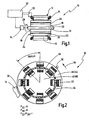
- FIG. 2 shows an embodiment of a synchronous machine according to the invention, whose structure is generally the in FIG. 1 corresponds shown construction. The same elements are therefore provided with the same reference numerals. In the following, only the differences are explained.
- the synchronous machine 10 of FIG. 2 has a double rotor arrangement, with a radially outer hollow rotor 40 (first rotor section 24), and a radially inner full rotor 42 (second rotor section 18).
- the two rotor sections 40, 42 are separated by a non-magnetic, low-friction intermediate sleeve 44.
- FIG. 2 Furthermore, the rotor flux 36 acting in the air gap 30 FIG. 2 a rotating field 38 indicated, which is generated by the winding assembly 14.
- the solid rotor 42 is movable relative to the hollow rotor 40 between two positions.
- the two relative positions of which in FIG. 2 a position is shown spaced apart by 360 ° / p, where p is the number of poles.
- the poles of the rotor sections 40, 42 are each formed by permanent magnets, which are magnetized in the radial direction.
- the magnetic poles of the permanent magnet arrangements 22, 26 are alternately reversed in the circumferential direction. In the illustrated relative position, the individual permanent magnets of the permanent magnet arrangements 22, 26 lie radially one above the other, wherein they are each poled in the same direction. Therefore, the magnetic fluxes generated by the permanent magnets of the permanent magnet arrangement 22, 26 are superimposed (essentially add up).
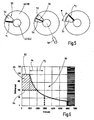
- FIG. 3a shows an arrangement as shown in FIG. 2 is shown, with a first relative position ⁇ 1 .
- the opposed poles of the permanent magnets of the permanent magnet assemblies 22, 26 are opposite so that magnetic attraction forces 45 act therebetween.
- this relative position ⁇ 1 is generally maintained due to these forces 45, even if no energy is supplied from the outside.
- a mechanical stop is shown, but not necessarily required.
- a mechanical stop 48 is provided which corresponds to the angular position 360 ° / p + ⁇ . In this position, the resulting magnetic repulsion forces 47 are skewed and include a circumferential force component that urges the solid rotor 42 against the mechanical stop 48.
- FIG. 4 an alternative embodiment of a dual rotor arrangement is shown, wherein the representation of those of FIG. 3 equivalent.
- a hollow rotor 40 ' has a Permanent magnet assembly 22 ', in which individual permanent magnets are set so that their magnetic axes in the circumferential direction (direction of rotation 28) have.
- the permanent magnets of the permanent magnet assembly 26 'on the solid rotor 42' are defined in a corresponding manner.
- two mechanical stops 46 ', 48' are also provided, which set up an offset angle range ⁇ 'of exactly 360 ° / p.
- the second mechanical stop 48 ' is provided as well as in the embodiment of FIG. 3b , so that a magnetic latching device is realized.
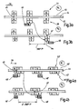
- FIG. 5 shows an example of an actuator for rotating the solid rotor 42 with respect to the hollow rotor 40.
- the actuator 50 is formed as a fluid rotary actuator and includes a first chamber 52 and a second chamber 54, which are separated by a rotary piston 56.
- the rotary piston 56 is fixed to the solid rotor 42.
- the first relative position ⁇ 1 is established.
- the solid rotor 42 is inserted into the in FIG. 5 rotated to the right (second relative position ⁇ 2 ).
- a center position is in FIG. 5 shown in the middle.
- Such middle positions are preferably not used in the present invention.
- Shown at 58 is an alternative rotor actuator 58 in the form of an electric motor connected to the solid rotor 42.
- FIG. 6 shows in schematic form a characteristic curve 60 of torque over rotational speed of a synchronous machine 10 according to the invention.
- the characteristic curve 60 essentially consists of two partial characteristics 62, 64.
- the part characteristic 62 corresponds to the characteristic of a conventional synchronous machine which is optimized for high torque. It can be seen that the characteristic curve 62 already breaks off at a relatively low rotational speed (for example 3,000 revolutions / minute). A conventional synchronous machine with such a high initial torque is usually not suitable for higher speeds.
- the second characteristic curve 64 has a significantly lower initial torque, but can be used up to relatively high rotational speeds (for example, 6,000 revolutions / minute).
- the synchronous machine 10 can now realize a characteristic curve 60, which advantageously consists of the two partial characteristics 62, 64.
- a first relative position ⁇ 1 is established, so that a high rotor flux 36 is provided and a high torque can be realized.
- the torque surplus achieved in this area is in FIG. 6 indicated schematically (hatch 66).
- the rotor flux 36 is reduced and the synchronous machine 10 can generally also be used for high rotational speeds, for example up to the example shown in the value of 6,000 revolutions / minute.
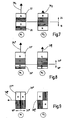
- FIG. 7 this is based on the synchronous machine 10 of FIG. 2 shown.
- the magnetic fluxes of the permanent magnet arrangements 22, 26 add up to a relatively high rotor flux 36 1 .
- the magnetic fluxes of the permanent magnet arrangements 22, 26 are partially extinguished due to the alternately polarized arrangement, so that a significantly smaller rotor flux 36 2 is provided.
- FIG. 8 an alternative embodiment is shown in which at the first rotor portion 24 "comparatively large permanent magnets are provided, and at the second rotor portion 18" comparatively small permanent magnets.
- a high rotor flux 36 1 " can again be provided in total in the first relative position ⁇ 1.
- a reduced rotor flux 36 2 " can be provided, which however is not so much less as in the case of FIG. 7 ,
- FIG. 9 shows a further alternative embodiment whose structure substantially the structure of FIG. 4 equivalent.
- FIG. 10 shows one of the FIG. 2 Comparable illustration of a further alternative embodiment of a double rotor arrangement 16 IV .
- the double-rotor arrangement 16 IV has a rotor yoke 18 IV or a solid rotor 42 IV and a first rotor section 24 IV or a hollow rotor 40 IV .
- first magnetic flux generating means 22 IV are formed on the hollow rotor 40 IV. These include first magnets which project into a gap between hollow rotor 40 IV and full rotor 42 IV , and second magnets, which are arranged in the circumferential direction next to it and do not protrude into the gap.
- first position (not shown), the magnets of the full rotor 42 IV are aligned in the radial direction with the second magnet of the hollow rotor 40 IV .
- a comparatively small first pole width 80 is set up in the circumferential direction.
- the rotor sections 40 IV , 42 IV are rotated against each other such that the magnets of the solid rotor 42 IV are adjacent to each circumferentially offset first magnets of the magnetic flux generating means 22 IV of the hollow rotor 40 IV .
- a second, wider pole width 82 is set up.
- a double rotor assembly 16 IV the rotor flux can thus be changed by changing the air gap surface, which in one case, for example, the first pole width 80 and in the other case, for example, the second pole width 82 corresponds.
- the polarity of the magnetic flux generating means 22 IV and magnetic flux generating means 26 IV may be selected as illustrated, with a larger rotor flux being established in the larger pole width position 82. In the position with the first pole width 80, a lesser rotor flux is altogether provided, since the magnets of the solid rotor 42 IV and the radially aligned second magnets of the hollow rotor 40 IV are oppositely poled.
- FIG. 11 It is shown how the electric currents of the synchronous electric machine 10 according to the present invention by mechanical field weakening, ie due to mechanical adjustment of the rotor 16 can be changed.
- diagram 90 are shown on the one hand, the motor current 33 1 in a first relative position and the motor current 33 2 in a second relative position (with field weakening due to mechanical adjustment).
- a torque-generating current without (92 1 ) and with (92 2 ) mechanically adjusted field weakening are shown in diagram 90, and a field-forming current 94 1 without field weakening and with field weakening (94 2 ) is shown.
- FIG. 12 shows a further embodiment of a double rotor arrangement 16 V for a synchronous electrical machine according to the present invention.
- FIG. 12a shows a first relative position ⁇ 1 and FIG. 12b shows a second relative position ⁇ 2 .
- the magnetic flux generating means 22 V of the hollow rotor 40 V and the magnetic flux generating means 26 V of the solid rotor 42 V are arranged so that they are radially aligned with each other in a first position and are in each case oppositely poled, so that the poles thus arranged are each weakened.
- each two adjacent poles are the same polarity, as in Fig. 12a is shown.
- a second position ( Fig. 12b ) are the rotor sections 40 V , 42 V offset from each other so that the number of poles of the rotor 16 V is doubled in total. Because in the second relative position, the magnets of the magnetic flux generating means 26 V are each between the magnets of the magnetic flux generating means 22 V , so that the number of poles is doubled.
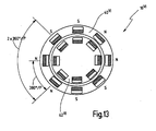
- FIG. 13 Another such variant with a double rotor assembly 16 VI with Polierever ein is in Fig. 13 shown.
- the poles of the hollow rotor and the rotor are radially aligned with each other in both relative positions.
- the magnets are each Gleichpolpolt, so that the poles are all unattenuated.
- the pole sequence is N-N-S-S-N-N-S-S in the circumferential direction, so that effectively only 4 poles are established (each formed by a pole pair).
- the permanent magnets of the permanent magnet assembly 26 of the solid rotor 42 can be inserted radially from the outside in recesses.
- a bandage, as is necessary in conventional EC machines for the rotor is not necessary for the solid rotor 42, since the intermediate sleeve 44 and arranged around the intermediate sleeve 44 around hollow rotor 40 prevent the permanent magnets of the assembly 26 are radially ejected.
- the above-mentioned small offset angle ⁇ can be in the range of 0.5 to 10 °, preferably in the range of 1 to 4 °.
- Suitable rotor actuators are fluid actuators or electric adjusting actuators, as are known, for example, in the field of camshaft adjustment or propeller adjustment.
Applications Claiming Priority (2)
| Application Number | Priority Date | Filing Date | Title |
|---|---|---|---|
| DE102006026593A DE102006026593B4 (de) | 2006-05-31 | 2006-05-31 | Elektrische Synchronmaschine |
| PCT/EP2007/003698 WO2007137657A1 (de) | 2006-05-31 | 2007-04-26 | Elektrische synchronmaschine |
Publications (2)
| Publication Number | Publication Date |
|---|---|
| EP2022158A1 EP2022158A1 (de) | 2009-02-11 |
| EP2022158B1 true EP2022158B1 (de) | 2014-03-26 |
Family
ID=38261667
Family Applications (1)
| Application Number | Title | Priority Date | Filing Date |
|---|---|---|---|
| EP07724628.8A Active EP2022158B1 (de) | 2006-05-31 | 2007-04-26 | Elektrische synchronmaschine |
Country Status (6)
| Country | Link |
|---|---|
| US (1) | US7884518B2 (ja) |
| EP (1) | EP2022158B1 (ja) |
| JP (1) | JP2009539336A (ja) |
| CN (1) | CN101454962B (ja) |
| DE (1) | DE102006026593B4 (ja) |
| WO (1) | WO2007137657A1 (ja) |
Families Citing this family (14)
| Publication number | Priority date | Publication date | Assignee | Title |
|---|---|---|---|---|
| DE102006026593B4 (de) * | 2006-05-31 | 2010-04-08 | Getrag Getriebe-Und Zahnradfabrik Hermann Hagenmeyer Gmbh & Cie Kg | Elektrische Synchronmaschine |
| WO2009155467A2 (en) * | 2008-06-18 | 2009-12-23 | Duffey Christopher K | Variable speed synchronous generator |
| JP5623412B2 (ja) * | 2009-09-25 | 2014-11-12 | 橋本義肢製作株式会社 | 下肢継手装具及びその制御方法 |
| US8368260B2 (en) * | 2010-10-28 | 2013-02-05 | National Dong Hwa University | Instantaneous magnetodynamic generator |
| BRPI1102856A2 (pt) * | 2011-04-25 | 2013-06-25 | Luis Augusto Pinto Carneiro | motor elÉtrico de aproveitamento duplo |
| KR20130092302A (ko) | 2012-02-10 | 2013-08-20 | 삼성전자주식회사 | 고정자 모듈 및 이를 포함하는 전동기 |
| DE102013004058A1 (de) * | 2013-03-08 | 2014-09-11 | Volkswagen Aktiengesellschaft | Vorrichtung für eine Elektro-Maschine |
| US11353084B2 (en) * | 2013-03-15 | 2022-06-07 | Clearmotion Acquisition I Llc | Rotary actuator driven vibration isolation |
| TWI516000B (zh) * | 2013-08-20 | 2016-01-01 | 林聖梁 | 馬達 |
| RU2581338C1 (ru) * | 2015-05-15 | 2016-04-20 | Сергей Михайлович Есаков | Магнитоэлектрический генератор |
| GB201709455D0 (en) * | 2017-06-14 | 2017-07-26 | Rolls Royce Plc | Electrical machine |
| US10714988B2 (en) * | 2017-08-24 | 2020-07-14 | Uchicago Argonne, Llc | Permanent magnet design to enable higher magnetic flux density |
| US20190093746A1 (en) * | 2017-09-22 | 2019-03-28 | Exedy Corporation | Dynamic damper device |
| FR3088506B1 (fr) * | 2018-11-09 | 2021-06-25 | Circor Ind | Procede de reduction du couple de crantage produit par des moteurs electriques de type brushless utilises simultanement |
Family Cites Families (26)
| Publication number | Priority date | Publication date | Assignee | Title |
|---|---|---|---|---|
| DE2106057A1 (de) * | 1971-02-09 | 1972-09-14 | Bosch Gmbh Robert | Wechselstromgenerator |
| JPS49131505U (ja) * | 1973-03-12 | 1974-11-12 | ||
| US4305031A (en) * | 1979-05-15 | 1981-12-08 | Lucas Industries Limited | Rotary electrical machine |
| US4562367A (en) * | 1982-06-30 | 1985-12-31 | Mitsubishi Denki Kabushiki Kaisha | Low inertia, speed variable induction motor |
| DE3420370A1 (de) * | 1984-01-02 | 1985-07-11 | Robert Bosch Gmbh, 7000 Stuttgart | Induktionsmotor |
| DE8419864U1 (ja) * | 1984-07-03 | 1986-11-13 | Fleckenstein, Volker, Dipl.-Ing., 8500 Nuernberg, De | |
| DE3609835A1 (de) * | 1986-03-22 | 1987-09-24 | Bosch Gmbh Robert | Einphasenmotor |
| JPH0674809B2 (ja) * | 1989-04-13 | 1994-09-21 | いすゞ自動車株式会社 | 高速回転軸用軸受装置 |
| JP3063229B2 (ja) * | 1991-04-27 | 2000-07-12 | 株式会社佐竹製作所 | 同期電動機 |
| JPH10155262A (ja) * | 1996-09-30 | 1998-06-09 | Hitachi Metals Ltd | 磁石式ブラシレス電動機 |
| US5821710A (en) * | 1996-09-30 | 1998-10-13 | Hitachi Metals, Ltd. | Brushless motor having permanent magnets |
| DE19652490A1 (de) * | 1996-12-17 | 1998-06-18 | Philips Patentverwaltung | Magnetisches Getriebe |
| JP4147732B2 (ja) * | 2000-08-11 | 2008-09-10 | 株式会社デンソー | 永久磁石型回転電機 |
| US6175178B1 (en) * | 1999-10-21 | 2001-01-16 | Christopher N. Tupper | Low inductance electrical machine for flywheel energy storage |
| US6320488B1 (en) * | 2000-07-31 | 2001-11-20 | The United States Of America As Represented By The Secretary Of The Army | Magic cylinder adjustable in field strength |
| JP4666806B2 (ja) * | 2000-11-01 | 2011-04-06 | 信越化学工業株式会社 | 永久磁石型回転電動機 |
| GB0104212D0 (en) | 2001-02-21 | 2001-04-11 | Johnson Electric Sa | Motor casing |
| JP3879413B2 (ja) * | 2001-02-28 | 2007-02-14 | 株式会社日立製作所 | 搬送システム及び回転電機 |
| JP4013487B2 (ja) * | 2001-02-28 | 2007-11-28 | 株式会社日立製作所 | 回転電機及びそれを搭載した車両 |
| US6844647B2 (en) * | 2002-08-27 | 2005-01-18 | Seiberco Incorporated | Permanent magnet motor having flux density characteristics that are internally variable |
| EP1416616B1 (en) * | 2002-10-26 | 2010-06-09 | LG Electronics Inc. | Electric motor |
| US20040131984A1 (en) * | 2003-01-06 | 2004-07-08 | Satek Larry C. | Low NOx burner |
| GB0312486D0 (en) * | 2003-05-30 | 2003-07-09 | Univ Bath | Improvements in or relating to electromotive machines |
| JP4324025B2 (ja) * | 2004-06-14 | 2009-09-02 | キヤノン株式会社 | 駆動装置 |
| KR100631551B1 (ko) * | 2004-12-21 | 2006-10-09 | 엘지전자 주식회사 | 이중자석 하이브리드 유도 전동기 |
| DE102006026593B4 (de) * | 2006-05-31 | 2010-04-08 | Getrag Getriebe-Und Zahnradfabrik Hermann Hagenmeyer Gmbh & Cie Kg | Elektrische Synchronmaschine |
-
2006
- 2006-05-31 DE DE102006026593A patent/DE102006026593B4/de active Active
-
2007
- 2007-04-26 WO PCT/EP2007/003698 patent/WO2007137657A1/de active Application Filing
- 2007-04-26 JP JP2009512436A patent/JP2009539336A/ja active Pending
- 2007-04-26 EP EP07724628.8A patent/EP2022158B1/de active Active
- 2007-04-26 CN CN2007800197963A patent/CN101454962B/zh active Active
-
2008
- 2008-12-01 US US12/326,022 patent/US7884518B2/en active Active
Also Published As
| Publication number | Publication date |
|---|---|
| DE102006026593A1 (de) | 2007-12-20 |
| CN101454962A (zh) | 2009-06-10 |
| JP2009539336A (ja) | 2009-11-12 |
| EP2022158A1 (de) | 2009-02-11 |
| US20090140591A1 (en) | 2009-06-04 |
| US7884518B2 (en) | 2011-02-08 |
| CN101454962B (zh) | 2012-05-02 |
| DE102006026593B4 (de) | 2010-04-08 |
| WO2007137657A1 (de) | 2007-12-06 |
Similar Documents
| Publication | Publication Date | Title |
|---|---|---|
| EP2022158B1 (de) | Elektrische synchronmaschine | |
| EP1380094B1 (de) | Elektromotor, insbesondere elektronisch kommutierter gleichstrommotor | |
| DD262310A5 (de) | Elektrische maschine | |
| EP3646438B1 (de) | Permanentmagnet-erregter motor mit verdrehbaren magnetstäben | |
| EP0954087A1 (de) | Elektrodynamisches Getriebe und Kreiselpumpe mit einem derartigen Getriebe | |
| EP3479462B1 (de) | Elektrisches maschinensystem | |
| EP3545610B1 (de) | Synchron-maschine mit magnetischer drehfelduntersetzung und flusskonzentration | |
| DE4341128A1 (de) | Vorrichtung zum Erzeugen hoher Drehzahlen | |
| EP0990297A1 (de) | Magnetgelagerter elektrischer antrieb | |
| EP2104976B1 (de) | Elektrische maschine | |
| DE102015110652B4 (de) | Rotor-stator-anordnung für eine hybriderregte synchronmaschine und ein rotor dafür | |
| WO2023179814A1 (de) | Elektrische maschine | |
| AT523723B1 (de) | Getriebemotor | |
| DE102015016978A1 (de) | Elektrische Maschine für ein Kraftfahrzeug und Kraftfahrzeug | |
| WO2005013465A1 (de) | Kraftfahrzeugstellantrieb | |
| WO2021164815A1 (de) | Elektromotor mit feldverstärkung | |
| EP1158648B1 (de) | Elektromagnetischer Drehantrieb | |
| EP1758229B1 (de) | Elektromotor | |
| WO2021110203A1 (de) | Elektrische axialflussmaschine und antriebssystem | |
| DE10257906A1 (de) | Schrittmotor mit mehreren Statoren | |
| WO1999063646A1 (de) | Dreiphasengleichstrommotor mit elektronischer kommutierung und hoher motorleistung | |
| DE4306327A1 (de) | Reluktanzmotor | |
| DE19858304A1 (de) | Wechselstrommaschine mit transversaler Flußführung, insbesondere zweipolige Transversalflußmaschine für hohe Drehzahl | |
| AT522827B1 (de) | Verkoppeltes Maschinensystem | |
| EP3700068A1 (de) | Elektrische maschine |
Legal Events
| Date | Code | Title | Description |
|---|---|---|---|
| PUAI | Public reference made under article 153(3) epc to a published international application that has entered the european phase |
Free format text: ORIGINAL CODE: 0009012 |
|
| 17P | Request for examination filed |
Effective date: 20081024 |
|
| AK | Designated contracting states |
Kind code of ref document: A1 Designated state(s): AT BE BG CH CY CZ DE DK EE ES FI FR GB GR HU IE IS IT LI LT LU LV MC MT NL PL PT RO SE SI SK TR |
|
| AX | Request for extension of the european patent |
Extension state: AL BA HR MK RS |
|
| DAX | Request for extension of the european patent (deleted) | ||
| RBV | Designated contracting states (corrected) |
Designated state(s): DE FR IT |
|
| 17Q | First examination report despatched |
Effective date: 20100511 |
|
| GRAP | Despatch of communication of intention to grant a patent |
Free format text: ORIGINAL CODE: EPIDOSNIGR1 |
|
| INTG | Intention to grant announced |
Effective date: 20131018 |
|
| GRAS | Grant fee paid |
Free format text: ORIGINAL CODE: EPIDOSNIGR3 |
|
| GRAA | (expected) grant |
Free format text: ORIGINAL CODE: 0009210 |
|
| RBV | Designated contracting states (corrected) |
Designated state(s): FR IT |
|
| REG | Reference to a national code |
Ref country code: DE Ref legal event code: R108 |
|
| AK | Designated contracting states |
Kind code of ref document: B1 Designated state(s): FR IT |
|
| REG | Reference to a national code |
Ref country code: DE Ref legal event code: R108 Effective date: 20140319 |
|
| PLBE | No opposition filed within time limit |
Free format text: ORIGINAL CODE: 0009261 |
|
| STAA | Information on the status of an ep patent application or granted ep patent |
Free format text: STATUS: NO OPPOSITION FILED WITHIN TIME LIMIT |
|
| 26N | No opposition filed |
Effective date: 20150106 |
|
| PG25 | Lapsed in a contracting state [announced via postgrant information from national office to epo] |
Ref country code: IT Free format text: LAPSE BECAUSE OF NON-PAYMENT OF DUE FEES Effective date: 20140426 |
|
| REG | Reference to a national code |
Ref country code: FR Ref legal event code: PLFP Year of fee payment: 10 |
|
| REG | Reference to a national code |
Ref country code: FR Ref legal event code: PLFP Year of fee payment: 11 |
|
| REG | Reference to a national code |
Ref country code: FR Ref legal event code: PLFP Year of fee payment: 12 |
|
| P01 | Opt-out of the competence of the unified patent court (upc) registered |
Effective date: 20230516 |
|
| PGFP | Annual fee paid to national office [announced via postgrant information from national office to epo] |
Ref country code: FR Payment date: 20230420 Year of fee payment: 17 |