EP2020384A2 - Behälter mit verbessertem Deckel - Google Patents
Behälter mit verbessertem Deckel Download PDFInfo
- Publication number
- EP2020384A2 EP2020384A2 EP08161767A EP08161767A EP2020384A2 EP 2020384 A2 EP2020384 A2 EP 2020384A2 EP 08161767 A EP08161767 A EP 08161767A EP 08161767 A EP08161767 A EP 08161767A EP 2020384 A2 EP2020384 A2 EP 2020384A2
- Authority
- EP
- European Patent Office
- Prior art keywords
- container
- component
- wall
- cap
- edge
- Prior art date
- Legal status (The legal status is an assumption and is not a legal conclusion. Google has not performed a legal analysis and makes no representation as to the accuracy of the status listed.)
- Withdrawn
Links
Images


Classifications
-
- B—PERFORMING OPERATIONS; TRANSPORTING
- B65—CONVEYING; PACKING; STORING; HANDLING THIN OR FILAMENTARY MATERIAL
- B65D—CONTAINERS FOR STORAGE OR TRANSPORT OF ARTICLES OR MATERIALS, e.g. BAGS, BARRELS, BOTTLES, BOXES, CANS, CARTONS, CRATES, DRUMS, JARS, TANKS, HOPPERS, FORWARDING CONTAINERS; ACCESSORIES, CLOSURES, OR FITTINGS THEREFOR; PACKAGING ELEMENTS; PACKAGES
- B65D41/00—Caps, e.g. crown caps or crown seals, i.e. members having parts arranged for engagement with the external periphery of a neck or wall defining a pouring opening or discharge aperture; Protective cap-like covers for closure members, e.g. decorative covers of metal foil or paper
- B65D41/02—Caps or cap-like covers without lines of weakness, tearing strips, tags, or like opening or removal devices
- B65D41/04—Threaded or like caps or cap-like covers secured by rotation
- B65D41/08—Threaded or like caps or cap-like covers secured by rotation engaging a threaded ring clamped on the external periphery of the neck or wall
- B65D41/083—Threaded or like caps or cap-like covers secured by rotation engaging a threaded ring clamped on the external periphery of the neck or wall engaging a bung-ring clamped on the neck or in the wall
-
- B—PERFORMING OPERATIONS; TRANSPORTING
- B65—CONVEYING; PACKING; STORING; HANDLING THIN OR FILAMENTARY MATERIAL
- B65D—CONTAINERS FOR STORAGE OR TRANSPORT OF ARTICLES OR MATERIALS, e.g. BAGS, BARRELS, BOTTLES, BOXES, CANS, CARTONS, CRATES, DRUMS, JARS, TANKS, HOPPERS, FORWARDING CONTAINERS; ACCESSORIES, CLOSURES, OR FITTINGS THEREFOR; PACKAGING ELEMENTS; PACKAGES
- B65D47/00—Closures with filling and discharging, or with discharging, devices
- B65D47/04—Closures with discharging devices other than pumps
- B65D47/06—Closures with discharging devices other than pumps with pouring spouts or tubes; with discharge nozzles or passages
- B65D47/061—Closures with discharging devices other than pumps with pouring spouts or tubes; with discharge nozzles or passages with telescopic, retractable or reversible spouts, tubes or nozzles
- B65D47/063—Closures with discharging devices other than pumps with pouring spouts or tubes; with discharge nozzles or passages with telescopic, retractable or reversible spouts, tubes or nozzles with flexible parts
Definitions
- the present invention relates to a container with an improved cap.
- metal containers for paint for example, always have a metal lid.
- the cap may be either a screw-on type or a plug forced into the outlet in the lid.
- the outlet in the case of a screw cap, the outlet must have a threaded collar on which to screw the cap.
- Known caps are not very safe, and are subject to leakage of the material from the container, particularly when the cap is put back on for the first time.
- the container is filled and the cap screwed on by means of automatic machines which, to screw the cap on, comprise a cap pickup device; and a device for first placing the cap onto the outlet in the container lid, and then rotating the cap with respect to the container to screw it on.
- automatic machines which, to screw the cap on, comprise a cap pickup device; and a device for first placing the cap onto the outlet in the container lid, and then rotating the cap with respect to the container to screw it on.
- Numeral 1 in Figures 1 and 2 indicates as a whole a cap for an outlet BC in a lid CP of a container 2 made of metal, plastic, or any other material.
- Cap 1 is defined by a first component 3 made of plastic material; and by a substantially capsule-shaped second component 4 also made of plastic material.
- Second component 4 comprises, in known manner, a substantially flat, circular main body 5.
- An inner first edge 6 and an outer second edge 7 project, substantially parallel to each other, from circular main body 5.
- Each of the two edges 6 and 7 is in the form of an annular body.
- edge 7 has an inner cylindrical surface 7a with helical projections 8, and a smooth outer cylindrical surface 7b.
- grooves or knurling are formed along the generating lines of outer cylindrical surface 7b to improve grip to screw and unscrew the cap.
- first component 3 comprises, on its outer wall 3a, a number of helical projections 9 which, in use, form a screw connection with projections 8 of second component 4.
- First component 3 also comprises an inner wall 3b.
- second component 4 is screwed to first component 3, and projections 8 of second component 4 are substantially screwed to projections 9 of first component 3.
- first component 3 comprises an annular cavity 10 between outer wall 3a and inner wall 3b.
- Outer wall 3a in turn comprises a portion 11a which narrows outwards to form a lead-in as explained in detail below.
- annular shoulder 14 is defined on outer wall 3a, inside annular cavity 10.
- lid CP has an outlet BC with a central axis of symmetry (A) off-centred with respect to the central axis of symmetry (B) of container 2 as a whole.
- outlet BC may obviously be coaxial with lid CP.
- Outlet BC is provided with a collar 15 having two portions 15a, 15b of different diameters and so defining an annular shoulder 15c in between. More specifically, portion 15a is the larger in diameter.
- annular shoulder 15c is on a level with lid CP.
- Wall 3b is vertically longer than wall 3a, and is formed with an annular shoulder 16, and a portion 11b also forming a lead-in (see below).
- One of the characteristics of the present invention lies in annular shoulder 15c of collar 15 resting on shoulder 16 on wall 3b of first component 3.
- walls 3a, 3b of first component 3 have respective annular shoulders 14, 16, on which a U-shaped edge 13 of collar 15 and annular shoulder 15c of collar 15 rest respectively.
- the double overlap fit (13-14; 15c-16) between first component 3 of cap 1 and collar 15 represents one of the main characteristics of the present invention.
- portions 11a and 11b which assist insertion of edge 13 inside cavity 10 when fitting cap 1 to collar 15.
- Inner wall 3b also comprises a number of cavities 11c equally spaced along the whole perimeter of inner wall 3b, and which enable full pour-out of the product from container 2, by extending up to annular shoulder 15c on collar 15, and so preventing the product from penetrating into the underside gap SQ formed between annular shoulder 15c and portion 11b of wall 3b.
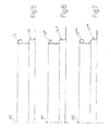
- Figure 5 shows the substantially semicircular collar 15 used in the Figure 1 and 2 embodiment.
- Figures 6 and 7 show another two embodiments of the collar.
- Figure 6 shows a collar 15* with a gable-type edge 13*.
- Figure 7 shows a collar 15** with a curled edge 13**.
- collars 15* and 15** are the same as for collar 15.
- Collars 15* and 15** can therefore be fitted to caps 1 of the type shown in Figure 2 .
- container 2 is positioned beneath a store (not shown) of caps 1; and a cap 1 is withdrawn from the store and pressed onto outlet BC.
- edge 13 of collar 15 is inserted inside cavity 10 until the free end of edge 13 comes to rest on annular shoulder 14 of first component 3.
- annular shoulder 15c of collar 15 comes to rest on shoulder 16 of first component 3.
- Figure 3 shows a second embodiment of cap 1, which comprises a plastic inner partition 20 formed in one piece with first component 3 and perpendicular to the axis (A) of cap 1.
- a tear-off portion 21 is formed along the connecting edge between partition 20 and inner wall 3b of first component 3; and a tab 22, integral with partition 20, is fixed to the outer face 20a of partition 20 to serve as a grip by which to tear partition 20 off first component 3, after first unscrewing second component 4 off first component 3.
- Figure 4 shows a third embodiment of the present invention.
- wall 3b of first component 3 is elongated to substantially form a bellows SF, the end portion of which has projections 9 which are engaged, as already seen, by projections 8 on second component 4.
- second component 4 is screwed onto first component 3.
- Second component 4 comprises a circular plate 24 divided into a circular central first portion 24a and an annular peripheral second portion 24b, which are joined by a number of radial segments 24c and by two radial bridges 24d.
- the radial bridges 24d divide annular peripheral second portion 24b into two arcs 24b* and 24b**.
- one user lifts the two arcs 24b*, 24b** in the direction of arrow F to break segments 24c.
- the diametrically opposite radial bridges 24d do not break, and serve to ensure mechanical connection between circular central first portion 24a and annular peripheral second portion 24b even after segments 24c are broken by the user.
- the Figure 4 embodiment is particularly suitable for containers 2 containing liquid that is dangerous to handle, and when optimum sealing of the liquid is desired.
- cap 1 can be pressed onto outlet BC in the lid of container 2, i.e. by exerting force on cap 1 in the direction of outlet BC, and can therefore be fitted to outlet BC with no need for particularly complicated automatic machines, on account of cap 1 simply being pressed onto collar 15.
- cap 1 can be fitted to collar 15 without the two having to be aligned accurately, on account of first component 3 defining a lead-in (portion 11a) for the outwardly bent portion of edge 13, and another lead-in (portion 11b) for the part of edge 13 connected to the top cylindrical portion of collar 15.
- the double overlap fit (13-14; 15c-16) between first component 3 of cap 1 and collar 15 represents one of the main characteristics of the present invention, ensures firm grip of collar 15 to cap 1, and so prevents random movement between the two resulting in leakage.
Landscapes
- Engineering & Computer Science (AREA)
- Mechanical Engineering (AREA)
- Closures For Containers (AREA)
- Tubes (AREA)
- Containers And Packaging Bodies Having A Special Means To Remove Contents (AREA)
Applications Claiming Priority (1)
| Application Number | Priority Date | Filing Date | Title |
|---|---|---|---|
| ITBO20070559 ITBO20070559A1 (it) | 2007-08-03 | 2007-08-03 | Contenitore provvisto di un tappo di tipo perfezionato |
Publications (2)
| Publication Number | Publication Date |
|---|---|
| EP2020384A2 true EP2020384A2 (de) | 2009-02-04 |
| EP2020384A3 EP2020384A3 (de) | 2009-07-29 |
Family
ID=39941522
Family Applications (1)
| Application Number | Title | Priority Date | Filing Date |
|---|---|---|---|
| EP08161767A Withdrawn EP2020384A3 (de) | 2007-08-03 | 2008-08-04 | Behälter mit verbessertem Deckel |
Country Status (2)
| Country | Link |
|---|---|
| EP (1) | EP2020384A3 (de) |
| IT (1) | ITBO20070559A1 (de) |
Cited By (2)
| Publication number | Priority date | Publication date | Assignee | Title |
|---|---|---|---|---|
| EP2112086A1 (de) * | 2008-04-23 | 2009-10-28 | F.Ceredi S.P.A. | Behälter mit einem Deckel, einem Adapter und einer Verschlusskappe |
| EP3162728A1 (de) * | 2015-10-30 | 2017-05-03 | F. Ceredi S.p.A. | Behälter, abdichtungssystem und stopfen |
Family Cites Families (4)
| Publication number | Priority date | Publication date | Assignee | Title |
|---|---|---|---|---|
| FR1423463A (fr) * | 1965-02-03 | 1966-01-03 | Rieke Metal Products Corp | Fermeture de récipient |
| US5641099A (en) * | 1995-12-08 | 1997-06-24 | Rieke Corporation | Nestable pouring spout assembly |
| FR2755741B1 (fr) * | 1996-11-08 | 1998-12-11 | Deberque Didier Michel | Robinet encliquetable escamotable |
| US20040045967A1 (en) * | 2002-09-11 | 2004-03-11 | Becker Gordon P. | Reclosable metal beverage can |
-
2007
- 2007-08-03 IT ITBO20070559 patent/ITBO20070559A1/it unknown
-
2008
- 2008-08-04 EP EP08161767A patent/EP2020384A3/de not_active Withdrawn
Cited By (2)
| Publication number | Priority date | Publication date | Assignee | Title |
|---|---|---|---|---|
| EP2112086A1 (de) * | 2008-04-23 | 2009-10-28 | F.Ceredi S.P.A. | Behälter mit einem Deckel, einem Adapter und einer Verschlusskappe |
| EP3162728A1 (de) * | 2015-10-30 | 2017-05-03 | F. Ceredi S.p.A. | Behälter, abdichtungssystem und stopfen |
Also Published As
| Publication number | Publication date |
|---|---|
| ITBO20070559A1 (it) | 2009-02-04 |
| EP2020384A3 (de) | 2009-07-29 |
Similar Documents
| Publication | Publication Date | Title |
|---|---|---|
| US3113693A (en) | Multi-position snap cap for containers | |
| US10407220B2 (en) | Low weight closure having an improved gripping surface | |
| US20130062302A1 (en) | Ratcheting bottle | |
| US20180208356A1 (en) | Can End and Related Method | |
| EP3873822A1 (de) | Doppeldichtungsauskleidung und nicht entfernbare verschlussanordnung | |
| JP2015006917A (ja) | 移行栓付きスクイズ注出容器 | |
| KR101775809B1 (ko) | 캡 조립체 및 그 조립 방법 | |
| JP5818698B2 (ja) | キャップ組立体およびその打栓方法 | |
| JP6402946B2 (ja) | 計量キャップ | |
| JP4839804B2 (ja) | ボトル容器 | |
| JP5640355B2 (ja) | 注出口栓及び包装容器 | |
| EP2020384A2 (de) | Behälter mit verbessertem Deckel | |
| JP6096463B2 (ja) | アセプティック充填用キャップ付スパウト | |
| JP5483435B2 (ja) | 中栓 | |
| JP2016043989A (ja) | 注出口栓及び包装容器 | |
| JP2019001508A (ja) | キャップ付き容器 | |
| JP5437201B2 (ja) | 注出容器 | |
| JP5833937B2 (ja) | キャップ組立体およびその組立方法 | |
| CN111132908B (zh) | 瓶 | |
| JP5254701B2 (ja) | 金属製缶容器 | |
| US20250346409A1 (en) | Container closure and dispensation system | |
| JP2025067264A (ja) | 1ピース型開封履歴バンド付きキャップ構造体およびそのセット方法 | |
| JP4404253B2 (ja) | 簡易開口式容器蓋 | |
| JPH024056Y2 (de) | ||
| JP3875421B2 (ja) | 開口仮封止栓付缶 |
Legal Events
| Date | Code | Title | Description |
|---|---|---|---|
| PUAI | Public reference made under article 153(3) epc to a published international application that has entered the european phase |
Free format text: ORIGINAL CODE: 0009012 |
|
| AK | Designated contracting states |
Kind code of ref document: A2 Designated state(s): AT BE BG CH CY CZ DE DK EE ES FI FR GB GR HR HU IE IS IT LI LT LU LV MC MT NL NO PL PT RO SE SI SK TR |
|
| AX | Request for extension of the european patent |
Extension state: AL BA MK RS |
|
| PUAL | Search report despatched |
Free format text: ORIGINAL CODE: 0009013 |
|
| AK | Designated contracting states |
Kind code of ref document: A3 Designated state(s): AT BE BG CH CY CZ DE DK EE ES FI FR GB GR HR HU IE IS IT LI LT LU LV MC MT NL NO PL PT RO SE SI SK TR |
|
| AX | Request for extension of the european patent |
Extension state: AL BA MK RS |
|
| RIC1 | Information provided on ipc code assigned before grant |
Ipc: B65D 47/06 20060101ALI20090619BHEP Ipc: B65D 41/08 20060101AFI20081114BHEP |
|
| AKX | Designation fees paid | ||
| REG | Reference to a national code |
Ref country code: DE Ref legal event code: 8566 |
|
| STAA | Information on the status of an ep patent application or granted ep patent |
Free format text: STATUS: THE APPLICATION IS DEEMED TO BE WITHDRAWN |
|
| 18D | Application deemed to be withdrawn |
Effective date: 20100130 |