EP2020365A1 - Elementary panel, preferably profile shaped, in particular for forming a side wall for the loading space of a vehicle - Google Patents
Elementary panel, preferably profile shaped, in particular for forming a side wall for the loading space of a vehicle Download PDFInfo
- Publication number
- EP2020365A1 EP2020365A1 EP08300241A EP08300241A EP2020365A1 EP 2020365 A1 EP2020365 A1 EP 2020365A1 EP 08300241 A EP08300241 A EP 08300241A EP 08300241 A EP08300241 A EP 08300241A EP 2020365 A1 EP2020365 A1 EP 2020365A1
- Authority
- EP
- European Patent Office
- Prior art keywords
- panel
- wall
- shaped
- elementary
- leg
- Prior art date
- Legal status (The legal status is an assumption and is not a legal conclusion. Google has not performed a legal analysis and makes no representation as to the accuracy of the status listed.)
- Granted
Links
- 230000003014 reinforcing effect Effects 0.000 claims abstract description 9
- 125000006850 spacer group Chemical group 0.000 claims abstract description 8
- 230000000295 complement effect Effects 0.000 claims abstract description 6
- 238000005452 bending Methods 0.000 claims description 4
- 230000002787 reinforcement Effects 0.000 abstract 2
- 230000000694 effects Effects 0.000 description 4
- 229910052751 metal Inorganic materials 0.000 description 2
- 239000002184 metal Substances 0.000 description 2
- 238000000034 method Methods 0.000 description 2
- 239000000047 product Substances 0.000 description 2
- 229910052782 aluminium Inorganic materials 0.000 description 1
- XAGFODPZIPBFFR-UHFFFAOYSA-N aluminium Chemical compound [Al] XAGFODPZIPBFFR-UHFFFAOYSA-N 0.000 description 1
- 239000006227 byproduct Substances 0.000 description 1
- 238000010276 construction Methods 0.000 description 1
- 238000003780 insertion Methods 0.000 description 1
- 230000037431 insertion Effects 0.000 description 1
- 238000004519 manufacturing process Methods 0.000 description 1
- 150000002739 metals Chemical class 0.000 description 1
- 238000012986 modification Methods 0.000 description 1
- 230000004048 modification Effects 0.000 description 1
Images


Classifications
-
- B—PERFORMING OPERATIONS; TRANSPORTING
- B62—LAND VEHICLES FOR TRAVELLING OTHERWISE THAN ON RAILS
- B62D—MOTOR VEHICLES; TRAILERS
- B62D33/00—Superstructures for load-carrying vehicles
- B62D33/04—Enclosed load compartments ; Frameworks for movable panels, tarpaulins or side curtains
- B62D33/044—Enclosed load compartments ; Frameworks for movable panels, tarpaulins or side curtains built up with profiles of constant elongated shape, e.g. extruded, mechanically interconnected by coupling members, e.g. by clamping, riveting or bolting
-
- B—PERFORMING OPERATIONS; TRANSPORTING
- B62—LAND VEHICLES FOR TRAVELLING OTHERWISE THAN ON RAILS
- B62D—MOTOR VEHICLES; TRAILERS
- B62D29/00—Superstructures, understructures, or sub-units thereof, characterised by the material thereof
- B62D29/008—Superstructures, understructures, or sub-units thereof, characterised by the material thereof predominantly of light alloys, e.g. extruded
-
- F—MECHANICAL ENGINEERING; LIGHTING; HEATING; WEAPONS; BLASTING
- F16—ENGINEERING ELEMENTS AND UNITS; GENERAL MEASURES FOR PRODUCING AND MAINTAINING EFFECTIVE FUNCTIONING OF MACHINES OR INSTALLATIONS; THERMAL INSULATION IN GENERAL
- F16B—DEVICES FOR FASTENING OR SECURING CONSTRUCTIONAL ELEMENTS OR MACHINE PARTS TOGETHER, e.g. NAILS, BOLTS, CIRCLIPS, CLAMPS, CLIPS OR WEDGES; JOINTS OR JOINTING
- F16B5/00—Joining sheets or plates, e.g. panels, to one another or to strips or bars parallel to them
- F16B5/0004—Joining sheets, plates or panels in abutting relationship
- F16B5/008—Joining sheets, plates or panels in abutting relationship by a rotating or sliding and rotating movement
Definitions
- the invention relates to an elementary panel advantageously shaped like a profile, in particular to form a side wall of a product loading space of a vehicle, by assembly with other elementary panels of this type, along its lengths. upper and lower longitudinal edges, by means of rapid snap locking means, the panel being formed by two walls, an inner wall and an outer wall, connected by spacer walls, the inner wall comprising one of its assembly longitudinal edges a male hook member and at its other longitudinal edge a complementary female hook member, so that these male and female hook members of a panel can cooperate with male and female hook elements of a another panel, a longitudinal edge of the outer wall being U-shaped opening outwardly and extending parallel to this wall and whose inner branch it is longer and L-shaped to have at its free end a perpendicular flange extending substantially to the level of the lower face of the wall, while the other longitudinal edge is configured so as to engage in a U of another panel and has a rib which extends inwardly of the panel and is intended to bear against the inner face of the flange of
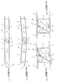
- FIG. 1A shows the assembly of two profiles of this type as is done for the realization of a side wall of a vehicle.
- the two walls bear the references 1a and 1b.
- the inner, outer and spacer walls of each profile are designated by the references 2, 3 and 4 respectively.
- the male hook element extending along an edge of the inner wall 2 is denoted 5 and the complementary hook element to the other edge of a panel is noted 6.
- the other longitudinal edge 15 of the wall 3 is configured to be received in the U-shaped edge 8 of another panel.
- the edge 15 of the panel 1b is received in the U-shaped edge 8 of the panel 1a.
- the end of the edge 15 is offset inward by a distance corresponding to the thickness of the wall 3, to bear against the inner face of the shorter outer leg 9 of the U 8.
- the edge comprises, at a distance from the end 16, the aforementioned rib noted 17, which, in the assembled state, as seen in the middle of the figure 1a , bears against the inner face of the flange 11 of the longer branch 10 of the U 8.
- the Figure 1B shows the behavior of the part of a wall formed by assembling the two panels 1a and 1b, under the effect of the forces F of a load, caused by products present in the loading space of the vehicle and exerting a pressure on the side wall of the vehicle.
- the L-shaped leg 10 at the edge of the outer wall 3 of the panel 1a flexes, with the result that the edge 15 of the panel 1b, which is locked in the U-shaped part 8 , in accordance with the Figure 1A can leave his home. This results in the rupture of the wall.
- the panels or profiles such as 1a and 1b are able to withstand charging pressures up to 5 Mtr. But when the load forces increase, the phenomenon illustrated in figure 1b , causing the rupture of the wall.
- the object of the invention is to propose panels in the form of profiles, which overcome the drawback which has just been described of known panels.
- a profile according to the invention is characterized in that the assembly edges are provided with means for reinforcing the bending resistance of the L-shaped locking leg.
- the panel is characterized in that the reinforcing means is formed by a support piece of the aforementioned locking leg.
- the elementary panel is characterized in that the support part comprises a support part of the elbow of the L-shaped limb and two support legs of the part which are supported by their end on the faces. inner and outer walls.
- the elementary panel is characterized in that the means for reinforcing the L-shaped branch comprises a support wall of the L-shaped branch which extends between the branch and the inner face facing each other. of the inner wall of the panel.
- the elementary panel is characterized in that the means for reinforcing the bending strength of the L-shaped locking leg comprises a bar which extends parallel to the edge of the wall. end and cooperates with a bearing heel on the inner surface of the outer wall of the panel.
- the elementary panel is characterized in that the panel is in the form of a profile.
- the first embodiment of the invention uses panels advantageously in the form of known profiles as shown in FIGS. Figures 1A and 1B and eliminates the problem of unlocking the profiles under the effect of too high load forces, by insertion between the two section ends to be locked of an additional support member designated by the reference 20.
- This support member 20 has an intermediate support portion 21 which abuts against the bent portion 27 of the L-shaped branch 10 and two legs supporting the support portion 21 whose free ends bear on internal faces of the angles 25, 26 of the two diagonally opposite sections 1a, 1b, to prevent, through the part 21, the support of the elbow 27 of the U locking profile 1a, the flexion of the branch 10.
- the support piece 20 is inserted before assembly and takes the final position according to the Figure 2A when the two sections are locked towards each other, at their ends.
- FIGS. 3A, 3B, 3C illustrate a second embodiment of the invention according to which the problem of unlocking the sections under the effect of too large loads is solved by providing on the branch 10 in the form of an L, of the locking U 8, an additional bar 28, which is parallel to the perpendicular flange 11 and located therebetween and the birth of the branch.
- On the complementary locking end 15 is provided a heel 30 which protrudes from the inner face of the wall 3, and is arranged so that the bar 28 is placed in the assembled state of the two sections, between the rib 17 and the heel 30, as seen on the figure 3B and bears against the heel when load forces F apply against the inner face of the side wall obtained by assembling profiles according to the invention.
- the bar 28 is provided at its free end with a small hook 29 intended to cooperate with a complementary element on the heel 30 in order to ensure a good hold of the system.
- both the bar 28 and the heel 30 extend over the entire length of the assembly edge.
- the Figures 4A and 4B show a third embodiment. This provides a particular configuration of the longitudinal assembly edge of the profiles 1, which has the locking portion having the general shape of a U, with the inner leg 10 longer L. L-shaped part and the branch on the Figures 4A and 4B the references respectively 8 ', 10', the rim being denoted 11 '.
- the assembly edge comprises a spacer wall 32 advantageously inclined at an angle of 45 ° with respect to the spacer walls 4 of the profiles according to the first two embodiments. and which extends from the inner wall 2 to the L-branch 10 'by connecting thereto at a location 33 relatively close to the flange 11'.
- the edge 15 engaging in the U-shaped portion 8 ' has the configuration of the known profiles. This is also the case for the male and female locking elements 5 and 6 at the inner wall of the profiles.
- the spacer wall near the assembly edge having the edge 15 is also inclined with respect to the orthogonal direction of the walls, but at an angle less than 45 °.
- FIGS. 4b, 4c illustrate two different moments of the assembly process of the two sections shown 1a, 1b.
Landscapes
- Engineering & Computer Science (AREA)
- Mechanical Engineering (AREA)
- General Engineering & Computer Science (AREA)
- Chemical & Material Sciences (AREA)
- Combustion & Propulsion (AREA)
- Transportation (AREA)
- Architecture (AREA)
- Structural Engineering (AREA)
- Connection Of Plates (AREA)
- Body Structure For Vehicles (AREA)
Abstract
Description
L'invention concerne un panneau élémentaire avantageusement en forme d'un profilé, notamment pour former une paroi latérale d'un espace de chargement de produits d'un véhicule, par assemblage à d'autres panneaux élémentaires de ce type, le long de ses bords longitudinaux supérieur et inférieur, à l'aide de moyens de verrouillage rapides par encliquetage, le panneau étant formé par deux parois, une paroi intérieure et une paroi extérieure, reliées par des parois d'entretoise, la paroi interne comprenant à un de ses bords longitudinaux d'assemblage un élément de crochet mâle et à son autre bord longitudinal un élément de crochet femelle complémentaire, de façon que ces éléments de crochet mâle et femelle d'un panneau puisse coopérer avec des éléments de crochet femelle et mâle d'un autre panneau, un bord longitudinal de la paroi externe étant en forme d'un U s'ouvrant vers l'extérieur et s'étendant parallèlement à cette paroi et dont la branche intérieure est plus longue et en forme d'un L pour présenter à son extrémité libre un rebord perpendiculaire s'étendant sensiblement jusqu'au niveau de la face inférieure de la paroi, tandis que l'autre bord longitudinal est configuré de façon à s'engager dans un U d'un autre panneau et comporte une nervure qui s'étend vers l'intérieur du panneau et est destinée à être en appui contre la face interne du rebord du U de réception dudit autre panneau.The invention relates to an elementary panel advantageously shaped like a profile, in particular to form a side wall of a product loading space of a vehicle, by assembly with other elementary panels of this type, along its lengths. upper and lower longitudinal edges, by means of rapid snap locking means, the panel being formed by two walls, an inner wall and an outer wall, connected by spacer walls, the inner wall comprising one of its assembly longitudinal edges a male hook member and at its other longitudinal edge a complementary female hook member, so that these male and female hook members of a panel can cooperate with male and female hook elements of a another panel, a longitudinal edge of the outer wall being U-shaped opening outwardly and extending parallel to this wall and whose inner branch it is longer and L-shaped to have at its free end a perpendicular flange extending substantially to the level of the lower face of the wall, while the other longitudinal edge is configured so as to engage in a U of another panel and has a rib which extends inwardly of the panel and is intended to bear against the inner face of the flange of the U of said other panel reception.
Des panneaux en forme de profilés de ce type sont déjà connus. La
La
Des panneaux élémentaires de paroi en forme de profilés, tels que les panneaux 1a et 1b, qui sont connus, sont formés par des profilés en métal léger, par exemple en aluminium. Ces profilés, initialement d'une hauteur de 25 à 30 mm ont été dimensionnés pour des charges relativement faibles. La tendance à réduire les coûts dans le domaine de la construction des véhicules automobiles et l'augmentation des prix des métaux légers ont amené les constructeurs à fabriquer des panneaux élémentaires plus longs et plus hauts, par exemple jusqu'à des hauteurs de 40, 50 et 60 mm.Elementary wall panels in the form of profiles, such as
Les panneaux ou profilés tels que 1a et 1b sont en mesure de résister à des pressions de charge jusqu'à 5 Mtr. Mais, lorsque les forces de charge augmentent, il se présente le phénomène illustré à la
L'invention a pour but de proposer des panneaux en forme de profilés, qui pallient l'inconvénient qui vient d'être décrit des panneaux connus.The object of the invention is to propose panels in the form of profiles, which overcome the drawback which has just been described of known panels.
Pour atteindre ce but, un profilé selon l'invention est caractérisé en ce que les bords d'assemblage sont pourvus de moyens de renforcement de la résistance à la flexion de la branche de verrouillage en forme d'un L.To achieve this purpose, a profile according to the invention is characterized in that the assembly edges are provided with means for reinforcing the bending resistance of the L-shaped locking leg.
Selon une caractéristique de l'invention, le panneau est caractérisé en ce que le moyen de renforcement est formé par une pièce de support de la branche de verrouillage précitée.According to a characteristic of the invention, the panel is characterized in that the reinforcing means is formed by a support piece of the aforementioned locking leg.
Selon une autre caractéristique de l'invention, le panneau élémentaire est caractérisé en ce que la pièce de support comporte une partie de support du coude de la branche en L et deux jambes de support de la partie qui prennent appui par leur extrémité sur les faces internes des parois intérieure et extérieure.According to another characteristic of the invention, the elementary panel is characterized in that the support part comprises a support part of the elbow of the L-shaped limb and two support legs of the part which are supported by their end on the faces. inner and outer walls.
Selon encore une autre caractéristique de l'invention, le panneau élémentaire est caractérisé en ce que le moyen de renforcement de la branche en L comporte une paroi de support de la branche en L qui s'étend entre la branche et la face interne en regard de la paroi interne du panneau.According to yet another characteristic of the invention, the elementary panel is characterized in that the means for reinforcing the L-shaped branch comprises a support wall of the L-shaped branch which extends between the branch and the inner face facing each other. of the inner wall of the panel.
Selon encore une autre caractéristique de l'invention, le panneau élémentaire est caractérisé en ce que le moyen de renforcement de la résistance à la flexion de la branche de verrouillage en forme d'un L comporte une barrette qui s'étend parallèlement au rebord d'extrémité et coopère avec un talon d'appui sur la surface interne de la paroi externe du panneau.According to yet another characteristic of the invention, the elementary panel is characterized in that the means for reinforcing the bending strength of the L-shaped locking leg comprises a bar which extends parallel to the edge of the wall. end and cooperates with a bearing heel on the inner surface of the outer wall of the panel.
Selon encore une autre caractéristique de l'invention, le panneau élémentaire est caractérisé en ce que le panneau est en forme d'un profilé.According to yet another characteristic of the invention, the elementary panel is characterized in that the panel is in the form of a profile.
L'invention sera mieux comprise, et d'autres buts, caractéristiques, détails et avantages de celle-ci apparaîtront plus clairement dans la description explicative qui va suivre faite en référence aux dessins schématiques annexés donnés uniquement à titre d'exemple illustrant plusieurs modes de réalisation de l'invention et dans lesquels :
- les
figures 1A et 1B sont deux vues en coupe d'une partie de paroi latérale d'un espace de chargement de produits d'un véhicule, formé par assemblage de deux panneaux de paroi élémentaire en forme de profilé selon l'état de la technique ; - les
figures 2A et 2B sont des vues en coupe axiale de deux extrémités de deux panneaux en forme de profilés selon un premier mode de réalisation de l'invention, lafigure 2A illustrant les deux profilés au cours de leur assemblage et lafigure 2B les profiles à l'état assemblé ; - les
figures 3A, 3B et 3C illustrent un second mode de réalisation de l'invention, lafigure 3A montrant un seul profilé, lafigure 3B deux profilés assemblés et lafigure 3C les deux profiles de la figure B sous l'effet des forces de charge F et - les
figures 4A, B et C illustrent un troisième mode de réalisation de panneau en forme de profilés selon l'invention en montrant deux profilés à différents instants de leur assemblage.
- the
Figures 1A and 1B are two sectional views of a sidewall portion of a vehicle product loading space, formed by assembling two elementary profile wall panels according to the state of the art; - the
Figures 2A and 2B are views in axial section of two ends of two profiled panels according to a first embodiment of the invention, theFigure 2A illustrating the two sections during their assembly and theFigure 2B the profiles in the assembled state; - the
FIGS. 3A, 3B and 3C illustrate a second embodiment of the invention, thefigure 3A showing a single profile, thefigure 3B two assembled sections and thefigure 3C the two profiles of figure B under the effect of the load forces F and - the
Figures 4A, B and C illustrate a third embodiment of panel shaped profiles according to the invention showing two profiles at different times of their assembly.
Le premier mode de réalisation de l'invention, représenté aux
Comme il ressort des deux
Les
Bien entendu, aussi bien la barrette 28 que le talon 30 s'étendent sur toute la longueur du bord d'assemblage.Of course, both the
Les
La particularité de ce troisième mode de réalisation réside dans le fait que le bord d'assemblage comporte une paroi d'entretoise 32 inclinée avantageusement selon un angle de 45° par rapport aux parois d'entretoise 4 des profilés selon les deux premiers modes de réalisation et qui s'étend de la paroi interne 2 vers la branche en L 10' en se raccordant à celui-ci à un endroit 33 relativement proche du rebord 11'. On constate que le bord 15 s'engageant dans la partie en U 8' présente la configuration des profilés connus. Ceci est également le cas pour les éléments de verrouillage mâle et femelle 5 et 6 au niveau de la paroi interne des profilés. Dans la version de réalisation selon les
Les
On constate que le mode de réalisation selon les
Bien entendu, de multiples modifications peuvent être apportées à l'invention telle que décrite et représentée, sans sortir du cadre de l'invention, à condition d'éviter une déformation notamment par flexion de la branche en L 10,10' au bord d'assemblage des profilés.Of course, multiple modifications can be made to the invention as described and shown, without departing from the scope of the invention, provided to avoid a deformation, in particular by bending the L-
Claims (6)
Applications Claiming Priority (1)
| Application Number | Priority Date | Filing Date | Title |
|---|---|---|---|
| FR0756734A FR2919374B1 (en) | 2007-07-25 | 2007-07-25 | ELEMENTARY PANEL ADVANTAGEUALLY IN THE FORM OF A PROFILE, IN PARTICULAR FOR FORMING A LATERAL WALL OF A LOADING SPACE OF PRODUCTS OF A VEHICLE. |
Publications (2)
| Publication Number | Publication Date |
|---|---|
| EP2020365A1 true EP2020365A1 (en) | 2009-02-04 |
| EP2020365B1 EP2020365B1 (en) | 2011-06-08 |
Family
ID=39129024
Family Applications (1)
| Application Number | Title | Priority Date | Filing Date |
|---|---|---|---|
| EP20080300241 Active EP2020365B1 (en) | 2007-07-25 | 2008-07-21 | Elementary panel, preferably profile shaped, in particular for forming a side wall for the loading space of a vehicle |
Country Status (2)
| Country | Link |
|---|---|
| EP (1) | EP2020365B1 (en) |
| FR (1) | FR2919374B1 (en) |
Cited By (4)
| Publication number | Priority date | Publication date | Assignee | Title |
|---|---|---|---|---|
| WO2012007532A1 (en) * | 2010-07-13 | 2012-01-19 | Cnh Belgium N.V. | Grain tank cover for a combine harvester |
| EP2754576A1 (en) * | 2013-01-10 | 2014-07-16 | F. Hesterberg & Söhne GmbH & Co. KG | Lockable door assembly for a load vehicle superstructure |
| CN111619673A (en) * | 2019-02-28 | 2020-09-04 | 晟通科技集团有限公司 | Bottom frame of box body |
| CN114313029A (en) * | 2021-12-27 | 2022-04-12 | 江西日菱车业有限公司 | Carriage plate and production process thereof |
Citations (4)
| Publication number | Priority date | Publication date | Assignee | Title |
|---|---|---|---|---|
| FR1577610A (en) * | 1967-09-14 | 1969-08-08 | ||
| DE1945687A1 (en) * | 1969-09-10 | 1971-03-25 | Ver Deutsche Metallwerke Ag | Side wall for flatbed vehicles |
| EP0058376A1 (en) * | 1981-02-13 | 1982-08-25 | Austria Metall Aktiengesellschaft | Connection for interlocking metallic or plastic sections |
| FR2703114A1 (en) * | 1993-03-24 | 1994-09-30 | Trouillet Sa Atelier Carrosser | Device for joining at least two plates, particularly made of thin sheet |
-
2007
- 2007-07-25 FR FR0756734A patent/FR2919374B1/en not_active Expired - Fee Related
-
2008
- 2008-07-21 EP EP20080300241 patent/EP2020365B1/en active Active
Patent Citations (4)
| Publication number | Priority date | Publication date | Assignee | Title |
|---|---|---|---|---|
| FR1577610A (en) * | 1967-09-14 | 1969-08-08 | ||
| DE1945687A1 (en) * | 1969-09-10 | 1971-03-25 | Ver Deutsche Metallwerke Ag | Side wall for flatbed vehicles |
| EP0058376A1 (en) * | 1981-02-13 | 1982-08-25 | Austria Metall Aktiengesellschaft | Connection for interlocking metallic or plastic sections |
| FR2703114A1 (en) * | 1993-03-24 | 1994-09-30 | Trouillet Sa Atelier Carrosser | Device for joining at least two plates, particularly made of thin sheet |
Cited By (4)
| Publication number | Priority date | Publication date | Assignee | Title |
|---|---|---|---|---|
| WO2012007532A1 (en) * | 2010-07-13 | 2012-01-19 | Cnh Belgium N.V. | Grain tank cover for a combine harvester |
| EP2754576A1 (en) * | 2013-01-10 | 2014-07-16 | F. Hesterberg & Söhne GmbH & Co. KG | Lockable door assembly for a load vehicle superstructure |
| CN111619673A (en) * | 2019-02-28 | 2020-09-04 | 晟通科技集团有限公司 | Bottom frame of box body |
| CN114313029A (en) * | 2021-12-27 | 2022-04-12 | 江西日菱车业有限公司 | Carriage plate and production process thereof |
Also Published As
| Publication number | Publication date |
|---|---|
| EP2020365B1 (en) | 2011-06-08 |
| FR2919374B1 (en) | 2009-10-23 |
| FR2919374A1 (en) | 2009-01-30 |
Similar Documents
| Publication | Publication Date | Title |
|---|---|---|
| WO2006117308A2 (en) | Connector connecting a wiper blade to a driving arm | |
| EP2020365B1 (en) | Elementary panel, preferably profile shaped, in particular for forming a side wall for the loading space of a vehicle | |
| FR2968366A1 (en) | Elastic fixing clip for assembling e.g. two structures of motor vehicle, has elastically deformable attaching part comprising side walls with relief parts to cooperate orifice of structure for reception and for blocking clip in orifice | |
| FR2973747A1 (en) | SPACER AND PROFILE FOR SEAT SLIDER OF MOTOR VEHICLE | |
| FR2884582A1 (en) | DEVICE FOR THE SEALED COUPLING OF TWO SMOOTH TUBES | |
| FR2885625A1 (en) | Sidewall connecting device for constructing integrated formwork structural wall, has units integrating components of sidewalls, and thermal bridge breaking units located at insulating units that are disposed in space between sidewalls | |
| EP0799952B1 (en) | Method for assembling prefabricated panels for swimmingpool-walls and swimmingpool-wall obtained by this method | |
| FR2989153A1 (en) | Photovoltaic solar facility for producing electricity from solar energy on steel trough, has fixing rail comprising profile with end edges, each having form such that edge engages with raised edge so as to secure rail with wave rider | |
| FR2813624A1 (en) | Connecting/sealing extrusion for edge of sandwich panel used for wall facings or partitions has joint surface with tongue, groove and seals | |
| EP3334874A1 (en) | Reinforced, dynamic lifting anchor for a structural member | |
| FR2930315A1 (en) | C-shaped metallic section elements/furring strips connecting device for e.g. fixing faces to cover acoustic/thermal insulation blankets, has spaces possessing heights equal to thicknesses of edges so that edges are slid in respective spaces | |
| BE1026538B1 (en) | ACCESSORY FOR FIXING A GRILL PANEL TO A FENCE POST COMPRISING A LOCKING PIECE AND A CLAMPING PIECE | |
| EP0675989B1 (en) | Device for assembling two profiled sections and profiled sections with a male and/or female profile | |
| EP3081719A1 (en) | Connecting profile for a roof element, in particular for telescopic swimming-pool shelter | |
| EP1972749A1 (en) | Door, window or similar comprising means for laterally guiding the free edge of the central sealing joint | |
| EP2570566A2 (en) | Joint covering device for flooring | |
| EP2389324B1 (en) | Device for assembling components defining a cooking tool | |
| EP2453067B1 (en) | Permanent formwork panel and permanent formwork block comprising such a panel | |
| FR2732083A1 (en) | Simplified connector for joining metal sections for construction of exhibition stands | |
| EP3491316A1 (en) | Collector plate, corresponding header box and corresponding heat exchanger | |
| EP2055883B1 (en) | Method of manufacturing a construction bar by crimping, and construction bar thus obtained | |
| FR2981378A1 (en) | Basin realization device for e.g. underground swimming pool, has panels with honeycomb type inner structure, where vertical edges of panels cooperate with connection profiles to form closed volume of geometric shape corresponding to basin | |
| EP2148037B1 (en) | Sealing profile, in particular for the glass of a building window, and window including same | |
| EP2269848B1 (en) | Cross-member for a rear twist-beam axle suspension for a vechicle and method for its production | |
| FR3036544A1 (en) | CONTACT ELEMENT WITH A CONNECTING MEMBER FIXING BOTH SIDES |
Legal Events
| Date | Code | Title | Description |
|---|---|---|---|
| PUAI | Public reference made under article 153(3) epc to a published international application that has entered the european phase |
Free format text: ORIGINAL CODE: 0009012 |
|
| AK | Designated contracting states |
Kind code of ref document: A1 Designated state(s): AT BE BG CH CY CZ DE DK EE ES FI FR GB GR HR HU IE IS IT LI LT LU LV MC MT NL NO PL PT RO SE SI SK TR |
|
| AX | Request for extension of the european patent |
Extension state: AL BA MK RS |
|
| 17P | Request for examination filed |
Effective date: 20090723 |
|
| 17Q | First examination report despatched |
Effective date: 20090819 |
|
| AKX | Designation fees paid |
Designated state(s): CH DE FR LI |
|
| GRAP | Despatch of communication of intention to grant a patent |
Free format text: ORIGINAL CODE: EPIDOSNIGR1 |
|
| GRAS | Grant fee paid |
Free format text: ORIGINAL CODE: EPIDOSNIGR3 |
|
| GRAA | (expected) grant |
Free format text: ORIGINAL CODE: 0009210 |
|
| AK | Designated contracting states |
Kind code of ref document: B1 Designated state(s): CH DE FR LI |
|
| REG | Reference to a national code |
Ref country code: CH Ref legal event code: EP |
|
| REG | Reference to a national code |
Ref country code: DE Ref legal event code: R096 Ref document number: 602008007400 Country of ref document: DE Effective date: 20110721 |
|
| REG | Reference to a national code |
Ref country code: CH Ref legal event code: NV Representative=s name: TROESCH SCHEIDEGGER WERNER AG |
|
| REG | Reference to a national code |
Ref country code: CH Ref legal event code: PUE Owner name: POMMIER Free format text: POMMIER GROSS ALUMINIUM GMBH#IN DER GROBACH 18#61197 FLORSTADT (DE) -TRANSFER TO- POMMIER#7, AVENUE DE LA MARE Z.A. DES BETHUNES#95310 SAINT-OUEN L'AUMONE (FR) |
|
| REG | Reference to a national code |
Ref country code: FR Ref legal event code: TP Owner name: POMMIER, FR Effective date: 20120216 |
|
| REG | Reference to a national code |
Ref country code: DE Ref legal event code: R082 Ref document number: 602008007400 Country of ref document: DE Representative=s name: PATENTANWAELTE RUFF, WILHELM, BEIER, DAUSTER &, DE |
|
| PLBE | No opposition filed within time limit |
Free format text: ORIGINAL CODE: 0009261 |
|
| STAA | Information on the status of an ep patent application or granted ep patent |
Free format text: STATUS: NO OPPOSITION FILED WITHIN TIME LIMIT |
|
| 26N | No opposition filed |
Effective date: 20120309 |
|
| REG | Reference to a national code |
Ref country code: DE Ref legal event code: R082 Ref document number: 602008007400 Country of ref document: DE Representative=s name: PATENTANWAELTE RUFF, WILHELM, BEIER, DAUSTER &, DE Effective date: 20120402 Ref country code: DE Ref legal event code: R081 Ref document number: 602008007400 Country of ref document: DE Owner name: POMMIER, FR Free format text: FORMER OWNER: POMMIER GROSS ALUMINIUM GMBH, 61197 FLORSTADT, DE Effective date: 20120402 |
|
| REG | Reference to a national code |
Ref country code: DE Ref legal event code: R097 Ref document number: 602008007400 Country of ref document: DE Effective date: 20120309 |
|
| REG | Reference to a national code |
Ref country code: DE Ref legal event code: R082 Ref document number: 602008007400 Country of ref document: DE Representative=s name: PATENTANWAELTE RUFF, WILHELM, BEIER, DAUSTER &, DE |
|
| REG | Reference to a national code |
Ref country code: DE Ref legal event code: R082 Ref document number: 602008007400 Country of ref document: DE Representative=s name: PATENTANWAELTE RUFF, WILHELM, BEIER, DAUSTER &, DE Effective date: 20140325 Ref country code: DE Ref legal event code: R081 Ref document number: 602008007400 Country of ref document: DE Owner name: POMMIER, FR Free format text: FORMER OWNER: POMMIER, SAINT QUEN L'AUMONE, FR Effective date: 20140325 |
|
| REG | Reference to a national code |
Ref country code: FR Ref legal event code: PLFP Year of fee payment: 9 |
|
| PGFP | Annual fee paid to national office [announced via postgrant information from national office to epo] |
Ref country code: CH Payment date: 20160727 Year of fee payment: 9 |
|
| REG | Reference to a national code |
Ref country code: FR Ref legal event code: PLFP Year of fee payment: 10 |
|
| REG | Reference to a national code |
Ref country code: CH Ref legal event code: PL |
|
| PG25 | Lapsed in a contracting state [announced via postgrant information from national office to epo] |
Ref country code: CH Free format text: LAPSE BECAUSE OF NON-PAYMENT OF DUE FEES Effective date: 20170731 Ref country code: LI Free format text: LAPSE BECAUSE OF NON-PAYMENT OF DUE FEES Effective date: 20170731 |
|
| REG | Reference to a national code |
Ref country code: FR Ref legal event code: PLFP Year of fee payment: 11 |
|
| PGFP | Annual fee paid to national office [announced via postgrant information from national office to epo] |
Ref country code: DE Payment date: 20190930 Year of fee payment: 12 |
|
| REG | Reference to a national code |
Ref country code: DE Ref legal event code: R119 Ref document number: 602008007400 Country of ref document: DE |
|
| PG25 | Lapsed in a contracting state [announced via postgrant information from national office to epo] |
Ref country code: DE Free format text: LAPSE BECAUSE OF NON-PAYMENT OF DUE FEES Effective date: 20210202 |
|
| P01 | Opt-out of the competence of the unified patent court (upc) registered |
Effective date: 20230518 |
|
| PGFP | Annual fee paid to national office [announced via postgrant information from national office to epo] |
Ref country code: FR Payment date: 20230720 Year of fee payment: 16 |