EP2020317A2 - Structure for installing an air-conditioning duct to an air-conditioning unit - Google Patents
Structure for installing an air-conditioning duct to an air-conditioning unit Download PDFInfo
- Publication number
- EP2020317A2 EP2020317A2 EP08013549A EP08013549A EP2020317A2 EP 2020317 A2 EP2020317 A2 EP 2020317A2 EP 08013549 A EP08013549 A EP 08013549A EP 08013549 A EP08013549 A EP 08013549A EP 2020317 A2 EP2020317 A2 EP 2020317A2
- Authority
- EP
- European Patent Office
- Prior art keywords
- air
- duct
- conditioning
- supply outlet
- conditioning unit
- Prior art date
- Legal status (The legal status is an assumption and is not a legal conclusion. Google has not performed a legal analysis and makes no representation as to the accuracy of the status listed.)
- Granted
Links
Images


Classifications
-
- B—PERFORMING OPERATIONS; TRANSPORTING
- B60—VEHICLES IN GENERAL
- B60H—ARRANGEMENTS OF HEATING, COOLING, VENTILATING OR OTHER AIR-TREATING DEVICES SPECIALLY ADAPTED FOR PASSENGER OR GOODS SPACES OF VEHICLES
- B60H1/00—Heating, cooling or ventilating [HVAC] devices
- B60H1/00507—Details, e.g. mounting arrangements, desaeration devices
- B60H1/00514—Details of air conditioning housings
-
- B—PERFORMING OPERATIONS; TRANSPORTING
- B60—VEHICLES IN GENERAL
- B60H—ARRANGEMENTS OF HEATING, COOLING, VENTILATING OR OTHER AIR-TREATING DEVICES SPECIALLY ADAPTED FOR PASSENGER OR GOODS SPACES OF VEHICLES
- B60H1/00—Heating, cooling or ventilating [HVAC] devices
- B60H1/00507—Details, e.g. mounting arrangements, desaeration devices
- B60H1/00557—Details of ducts or cables
- B60H1/00564—Details of ducts or cables of air ducts
Definitions
- the present invention relates to a structure for installing an air-conditioning duct to a supply outlet of an air-conditioning unit mounted on vehicles.
- air-conditioning in vehicles are performed by using an air-conditioning duct to supply air-conditioning air discharged from an air-conditioning unit for vehicles to a predetermined position inside a vehicle and blow off the air.
- Ordinary air-conditioning units are provided with two supply outlets for air-conditioning air, and each of them are installed with a duct for supplying the air-conditioning air to a different position.
- Recently, in addition, some air-conditioning units are provided with a plurality of supply outlets to discharge air-conditioning air with different temperatures.
- JP. A. 6-106956 discloses a method for fitting one air-conditioning duct and other air-conditioning duct with a pawl part in advance to be integrally fixed, and then, connecting the integrated air-conditioning duct to the supply outlet.
- JP. A. 2004-98727 discloses a method using an air-conditioning case for sliding and fixing one end of an air-conditioning duct to an air-conditioning unit when installing a unit, such as an instrument panel, to which the air-conditioning duct is connected on a vehicle.
- FIG. 5 shows a conventional example with respect to a method for installing an air-conditioning duct to a supply outlet according to the present invention.
- two air-conditioning ducts 101 and 102 are incorporated in advance to form a fixed unit.
- a supply outlet 202 of the air-conditioning unit is formed in a state where a part (the front surface of the orbit for installing the duct indicated by an arrow) that is notched (a notched part K.)
- an air-conditioning duct unit 100 is moved closer to the supply outlet from the direction in which the notched part K is formed, and outer peripheral faces of the air-conditioning duct 100 is contacted with inner periphery faces of the supply outlets 201 and 202 for connection.
- a supply outlet boundary edge 200A of the air-conditioning unit and a boundary edge 100A of the air-conditioning duct are butt-jointed in almost line-contacted state. Therefore, so-called an air leakage phenomenon, where air-conditioning air discharged from one supply outlet 201 flows into a duct 102, or air-conditioning air discharged from other supply outlet 202 flows into a duct 101, can easily occurs.
- a joining section of the supply outlet boundary edge 200A of the air-conditioning unit and the boundary edge 100A of the air-conditioning duct must be provided with a seal material.
- the seal material In order to install the seal material to the joining section of the supply outlet boundary edge 200A of the air-conditioning unit and the boundary edge 100A of the air-conditioning duct, the seal material must be installed to the supply outlet boundary edge 200A of the air-conditioning unit or the boundary edge 100A of the air-conditioning duct before performing a connecting operation.
- an object of the present invention is to provide a structure for installing an air-conditioning duct to an air-conditioning unit so as to prevent an air leakage phenomenon.
- the present inventors have made keen studies based on the background as described above, and found that the above-mentioned subject can be solved by changing the shape of a joining section of an air-conditioning unit and an air-conditioning duct, and have completed the present invention based on the findings.
- the present invention relates to a structure for installing an air-conditioning duct to an air-conditioning unit, wherein the air-conditioning unit has a first air supply outlet and a second air supply outlet adjacent with each other, and the air-conditioning duct has a first air passage and a second air passage adjacent with each other, wherein the first air supply outlet and the second air supply outlet include a U-shaped auxiliary wall having a notched part at one side therearound and a supply outlet boundary wall separating the first air supply outlet and the second air supply outlet, and a duct side step part formed between an opening rim of the first duct and an opening rim of the second duct, the duct side step part is contacted with the supply outlet boundary wall to install the air-conditioning duct to the air-conditioning unit.
- the present invention also relates to a structure for installing an air-conditioning duct to an air-conditioning unit, wherein the duct side step part is formed by the opening rim of the first duct projecting farther than the opening rim of the second duct.
- the present invention also relates to a structure for installing an air-conditioning duct to an air-conditioning unit, wherein an air-conditioning side step part formed on the supply outlet boundary wall, the air-conditioning side step part is formed with an opening rim of the second air supply outlet shorter than an opening rim of the first air supply outlet, and the duct side step part is contacted with the air-conditioning side step part to install the air-conditioning duct to the air-conditioning unit.
- the present invention also relates to a structure for connecting an air-conditioning duct to an air-conditioning unit, wherein the size of the air-conditioning side step part is equal to that of the duct side step part.
- the present invention also relates to a structure for installing an air-conditioning duct to an air-conditioning unit, wherein the distance between the upper end of the U-shaped auxiliary wall and the upper end of the supply outlet boundary wall is shorter than the distance between the upper end of the U-shaped auxiliary wall and the upper end of the notched part.
- the present invention also relates to a structure for connecting an air-conditioning duct to an air-conditioning unit, wherein the supply outlet boundary wall and the duct side step part are contacted via a seal material.
- the present invention also relates to a structure for connecting an air-conditioning duct to an air-conditioning unit, wherein the air-conditioning duct is installed to the air-conditioning unit by sliding through the notched part.
- an air-conditioning duct can be installed to a supply outlet of an air-conditioning unit without causing an air leakage phenomenon.
- an air-conditioning duct having a plurality of air passages can be installed to an air-conditioning unit with high air-tightness maintained by connecting in the sliding direction.
- FIG. 1 is a perspective view of a supply outlet of an air-conditioning unit and an air-conditioning duct installed to the supply outlet according to the present embodiment.
- an air-conditioning unit 1 (so-called "an HVAC module") according to the present embodiment includes a first air supply outlet 11 having a rectangular shape and a second air supply outlet 12 having a rectangular shape, and generally, air-conditioning air with different temperatures is supplied from the first air supply outlets 11 and the second air supply outlet 12.
- the first air supply outlet 11 and the second air supply outlet 12 include a U-shaped auxiliary wall 2 having a notched part K at one side therearound, and a supply outlet boundary wall 130 separating the first air supply outlet 11 and the second air supply outlet 12.
- the first air supply outlet 11 and the second air supply outlet 12 are located side-by-side with the supply outlet boundary wall 130 therebetween, and wall face heights of the supply outlets of the air-conditioning unit 1 are formed in the order of the wall face with the notched part K, the supply outlet boundary wall 130, and the U-shaped auxiliary wall 2 with the wall with the notched part K lowest. That is, the distance (d2) between the upper end of the U-shaped auxiliary wall 2 and that of the supply outlet boundary wall 130 is shorter than the distance (d1) between the upper end of the U-shaped auxiliary wall 2 and that of the notched part K.
- an air-conditioning duct 3 is provided with a first duct 31 having a rectangular shape and a second duct 32 having a rectangular shape.
- the first duct 31 forms a first air passage of the air-conditioning duct
- the second duct 32 forms a second air passage of the air-conditioning duct.
- the shape of the opening of the first duct 31 consists with that of the first air supply outlet 11, and similarly, the shape of the opening of the second duct 32 consists with that of the second air supply outlet 12.
- a duct side step part Z is formed between the boundary wall 310 of the first duct 31 and the boundary wall 320 of the second duct 32.
- the boundary wall 310 of the first duct 31 indicates a peripheral wall adjacent to the second duct 32 among the peripheral walls forming the first duct 31.
- the boundary wall 320 of the second duct 32 indicates a peripheral wall adjacent to the first duct 31 among the peripheral walls forming the second duct 32.
- the duct side step part Z contacts the supply outlet boundary wall 130 via a seal material when connecting the air-conditioning duct 3 to the air-conditioning unit 1.
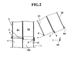
- FIG. 2 is a cross sectional view showing a state in which an air-conditioning duct 1 is installed to an air-conditioning unit 3.
- a seal material 4 is installed in advance at least on the front face of the first duct 31, and on the stepped part Z of the second duct 32.
- a packing made from polyurethane or the like is employed as the seal material 4.
- the seal material 4 is preferably fixed to a predetermined position of each duct by methods of adhesion and the like. Types of the seal material 4 are not particularly limited.
- the air-conditioning duct 3 is slid toward the supply outlet of the air-conditioning unit 1. That is, the air-conditioning duct 3 is slid from the side of the second air supply outlet 12 to pass through the notched part K.
- Wall face heights of the supply outlets of the air-conditioning unit 1 is formed in the order of the wall face with the notched part K, the supply outlet boundary wall 130, and the U-shaped auxiliary wall 2 with the wall with the notched part K lowest, and an opening end 31A of the first duct 31 is formed so as to be shorter than an opening end 32A of the second duct 32. Therefore, the front face of the first duct 31 passes through the notched part K and the supply outlet boundary wall, and advances to a position to contact the U-shaped auxiliary wall 2 on the side of the first air supply outlet.
- the air-conditioning duct 3 passes through the notched part K, and advances to a position in which the stepped part Z contacts the supply outlet boundary wall 130.
- the front face of the first duct 31 passes through the notched part K to contacts the inner periphery face of the U-shaped auxiliary wall 2 via the seal material 4, and the duct side step part Z contacts the supply outlet boundary wall 130 of the air-conditioning unit 1 via the seal material 4.
- the air-conditioning unit 1 and the air-conditioning duct 3 are connected with joining sections having certain areas except for the side with the notched part K.
- the air-conditioning duct 3 is airtightly connected to the air-conditioning unit 1 by sticking the seal material 4A so as to cover a bonded surface of the second air supply outlet 12 and the second duct 32 on the side of the notched part K.
- the duct side step part Z is provided on the air-conditioning duct 3 to ensure enough space for sticking the seal material 4, and achieves reliable and stable adhesion of the seal material 4. Furthermore, the duct side step part Z and the supply outlet boundary wall 130 are connected by contacting surfaces thereof, reliable sealing property between an air flow passage S1 formed with the first air supply outlet 11 and the first duct 31 and an air flow passage S2 formed with the second air supply outlet 12 and the second duct 32 can be obtained, and an occurrence of air leakage phenomenon is reliably prevented.
- the air-conditioning duct 3 is slid to install to the air-conditioning unit 1, when the front face of the first duct 31 is connected in contact with the inner periphery face of the U-shaped auxiliary wall 2, the whole perimeter is simultaneously connected except for the side with the notched part K of the air-conditioning duct 3, and sealing only the side with the notched part K at the end efficiently connects the air-conditioning duct 3 to the air-conditioning unit 1.
- a projection is provided on the wall surface of the air-conditioning duct 3, and a guide groove for receiving the projection provided on the air-conditioning duct 3 is provided on the wall surface of the U-shaped auxiliary wall 2. Since the projection of the air-conditioning duct 3 is guided to the guide groove of the U-shaped auxiliary wall 2, the air-conditioning duct 3 can be easily slid and inserted to the inside of the U-shaped auxiliary wall 2. As a result, separation of the seal material on the wall surface of the air-conditioning duct 3 by friction generated with the U-shaped auxiliary wall 2 while sliding is prevented.
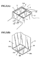
- FIG. 3 is a perspective view of a supply outlet of an air-conditioning unit in the present embodiment.
- an air-conditioning unit 1 in the present embodiment includes an opening rim 12A of a second air supply outlet 12 disposed lower than an opening rim 11A of a first air supply outlet, and therefore, a supply outlet boundary wall 130 formed with a boundary wall 110 of the first air supply outlet 11 and a boundary wall 120 of the second air supply outlet 12 is provided with a stepped part X (hereinafter, referred to as an "air-conditioning side step part").
- the size of the air-conditioning side step part X is equal to that of a duct side step part Z of an air-conditioning duct 3.
- the air-conditioning side step part X contacts the duct side step part Z via a seal material when installing the air-conditioning duct 3 to the air-conditioning unit 1.
- the air-conditioning side step part X is formed on the supply outlet boundary wall 130 to make positioning of the air-conditioning duct 3 easier when connecting the air-conditioning duct 3 to the air-conditioning unit 1, and provides a joining section with a certain area and stable airtightness.
- a U-shaped auxiliary wall 2 in the present embodiment is provided so as to surround the first air supply outlet 11 and the second air supply outlet 12, and to project from opening rims 11A and 12A in extending manner, and therefore, the whole inner periphery faces of the U-shaped auxiliary wall 2 work as a connection space Y with which a seal material 4 installed on the peripheral walls of the air-conditioning duct 3 contacts.
- a method for connecting the air-conditioning duct 3 to the supply outlet of the air-conditioning unit 1 in the second embodiment is the same as the method for connecting the air-conditioning duct 3 to the supply outlet of the air-conditioning unit 1 in the first embodiment mentioned above (See FIG. 4 .)
- seal material 4 is installed on the air-conditioning duct 3 in the embodiments, the seal material 4 can also be disposed on the air-conditioning 1. Separate seal materials can also be used.
- the features disclosed in the foregoing description, in the claims and/or in the accompanying drawings may, both separately and in any combination thereof, be material for realising the invention in diverse forms thereof.
Landscapes
- Physics & Mathematics (AREA)
- Thermal Sciences (AREA)
- Engineering & Computer Science (AREA)
- Mechanical Engineering (AREA)
- Duct Arrangements (AREA)
- Air-Conditioning For Vehicles (AREA)
Abstract
Description
- The present invention relates to a structure for installing an air-conditioning duct to a supply outlet of an air-conditioning unit mounted on vehicles.
- Currently, air-conditioning in vehicles are performed by using an air-conditioning duct to supply air-conditioning air discharged from an air-conditioning unit for vehicles to a predetermined position inside a vehicle and blow off the air.
Ordinary air-conditioning units are provided with two supply outlets for air-conditioning air, and each of them are installed with a duct for supplying the air-conditioning air to a different position.
Recently, in addition, some air-conditioning units are provided with a plurality of supply outlets to discharge air-conditioning air with different temperatures. - Wide variety of methods for installing an air-conditioning duct to an air-conditioning unit have been used, and for example,
JP. A. 6-106956
In addition,JP. A. 2004-98727 -
FIG. 5 shows a conventional example with respect to a method for installing an air-conditioning duct to a supply outlet according to the present invention.
According to this example, two air-conditioning ducts
Asupply outlet 202 of the air-conditioning unit is formed in a state where a part (the front surface of the orbit for installing the duct indicated by an arrow) that is notched (a notched part K.)
Subsequently, an air-conditioning duct unit 100 is moved closer to the supply outlet from the direction in which the notched part K is formed, and outer peripheral faces of the air-conditioning duct 100 is contacted with inner periphery faces of thesupply outlets - In the connecting method shown in
FIG. 5 , a supplyoutlet boundary edge 200A of the air-conditioning unit and aboundary edge 100A of the air-conditioning duct are butt-jointed in almost line-contacted state.
Therefore, so-called an air leakage phenomenon, where air-conditioning air discharged from onesupply outlet 201 flows into aduct 102, or air-conditioning air discharged fromother supply outlet 202 flows into aduct 101, can easily occurs.
In order to prevent the air leakage phenomenon, a joining section of the supplyoutlet boundary edge 200A of the air-conditioning unit and theboundary edge 100A of the air-conditioning duct must be provided with a seal material. - In order to install the seal material to the joining section of the supply
outlet boundary edge 200A of the air-conditioning unit and theboundary edge 100A of the air-conditioning duct, the seal material must be installed to the supplyoutlet boundary edge 200A of the air-conditioning unit or theboundary edge 100A of the air-conditioning duct before performing a connecting operation. - However, even if the seal material is installed on the supply
outlet boundary edge 200A of the air-conditioning unit or theboundary edge 100A of the air-conditioning duct, due to an extremely small contact area of the supplyoutlet boundary edge 200A of the air-conditioning unit and theboundary edge 100A of the air-conditioning duct, a connecting state is unstable depending on assembly conditions.
Furthermore, the seal material may be peeled off from the boundary edge when assembling, and enough sealing property may not be ensured.
Therefore, maintaining the assembled state so as to prevent the air leakage phenomenon is difficult. - The present invention was developed to solve the above-mentioned problems.
That is, an object of the present invention is to provide a structure for installing an air-conditioning duct to an air-conditioning unit so as to prevent an air leakage phenomenon. - The present inventors have made keen studies based on the background as described above, and found that the above-mentioned subject can be solved by changing the shape of a joining section of an air-conditioning unit and an air-conditioning duct, and have completed the present invention based on the findings.
- That is, the present invention relates to a structure for installing an air-conditioning duct to an air-conditioning unit, wherein the air-conditioning unit has a first air supply outlet and a second air supply outlet adjacent with each other, and the air-conditioning duct has a first air passage and a second air passage adjacent with each other, wherein the first air supply outlet and the second air supply outlet include a U-shaped auxiliary wall having a notched part at one side therearound and a supply outlet boundary wall separating the first air supply outlet and the second air supply outlet, and a duct side step part formed between an opening rim of the first duct and an opening rim of the second duct, the duct side step part is contacted with the supply outlet boundary wall to install the air-conditioning duct to the air-conditioning unit.
- Further, the present invention also relates to a structure for installing an air-conditioning duct to an air-conditioning unit, wherein the duct side step part is formed by the opening rim of the first duct projecting farther than the opening rim of the second duct.
- The present invention also relates to a structure for installing an air-conditioning duct to an air-conditioning unit, wherein an air-conditioning side step part formed on the supply outlet boundary wall, the air-conditioning side step part is formed with an opening rim of the second air supply outlet shorter than an opening rim of the first air supply outlet, and the duct side step part is contacted with the air-conditioning side step part to install the air-conditioning duct to the air-conditioning unit.
- The present invention also relates to a structure for connecting an air-conditioning duct to an air-conditioning unit, wherein the size of the air-conditioning side step part is equal to that of the duct side step part.
- The present invention also relates to a structure for installing an air-conditioning duct to an air-conditioning unit, wherein the distance between the upper end of the U-shaped auxiliary wall and the upper end of the supply outlet boundary wall is shorter than the distance between the upper end of the U-shaped auxiliary wall and the upper end of the notched part.
- The present invention also relates to a structure for connecting an air-conditioning duct to an air-conditioning unit, wherein the supply outlet boundary wall and the duct side step part are contacted via a seal material.
- The present invention also relates to a structure for connecting an air-conditioning duct to an air-conditioning unit, wherein the air-conditioning duct is installed to the air-conditioning unit by sliding through the notched part.
- Combining the above-mentioned aspects appropriately can be employed without deviating from the object of the present invention.
- According to a structure for installing an air-conditioning duct to an air-conditioning unit of the present invention, an air-conditioning duct can be installed to a supply outlet of an air-conditioning unit without causing an air leakage phenomenon.
In addition, an air-conditioning duct having a plurality of air passages can be installed to an air-conditioning unit with high air-tightness maintained by connecting in the sliding direction. - When an air-conditioning side step part provided on the air-conditioning unit and a duct side step part provided on the air-conditioning duct both have the same size, positioning in connecting the air-conditioning duct to the air-conditioning unit becomes easier, and a joining section with a certain area and stable airtightness can be ensured.
-
-
FIG. 1 is a perspective view of a supply outlet of an air-conditioning unit and an air-conditioning duct installed to the supply outlet according to the first embodiment; -
FIG. 2 is a cross sectional view showing a state in which the air-conditioning duct is installed to the air-conditioning unit according to the first embodiment; -
FIG. 3 is a perspective view of a supply outlet of an air-conditioning unit and an air-conditioning duct installed to a supply outlet according to the second embodiment; -
FIG. 4 is a cross sectional view showing a state in which the air-conditioning duct is connected to the air-conditioning unit according to the second embodiment; and -
FIG. 5 is a cross sectional view showing a method of a conventional example for installing an air-conditioning duct to an air-conditioning unit. - An embodiment of the present invention will be described with reference to the drawings.
FIG. 1 is a perspective view of a supply outlet of an air-conditioning unit and an air-conditioning duct installed to the supply outlet according to the present embodiment.
As shown inFIG. 1A , an air-conditioning unit 1 (so-called "an HVAC module") according to the present embodiment includes a firstair supply outlet 11 having a rectangular shape and a secondair supply outlet 12 having a rectangular shape, and generally, air-conditioning air with different temperatures is supplied from the firstair supply outlets 11 and the secondair supply outlet 12. - The first
air supply outlet 11 and the secondair supply outlet 12 include a U-shapedauxiliary wall 2 having a notched part K at one side therearound, and a supplyoutlet boundary wall 130 separating the firstair supply outlet 11 and the secondair supply outlet 12.
The firstair supply outlet 11 and the secondair supply outlet 12 are located side-by-side with the supplyoutlet boundary wall 130 therebetween, and wall face heights of the supply outlets of the air-conditioning unit 1 are formed in the order of the wall face with the notched part K, the supplyoutlet boundary wall 130, and the U-shapedauxiliary wall 2 with the wall with the notched part K lowest.
That is, the distance (d2) between the upper end of the U-shapedauxiliary wall 2 and that of the supplyoutlet boundary wall 130 is shorter than the distance (d1) between the upper end of the U-shapedauxiliary wall 2 and that of the notched part K. - As shown in
FIG. 1B , an air-conditioning duct 3 according to the present embodiment is provided with afirst duct 31 having a rectangular shape and asecond duct 32 having a rectangular shape.
Thefirst duct 31 forms a first air passage of the air-conditioning duct, and thesecond duct 32 forms a second air passage of the air-conditioning duct. The shape of the opening of thefirst duct 31 consists with that of the firstair supply outlet 11, and similarly, the shape of the opening of thesecond duct 32 consists with that of the secondair supply outlet 12.
When connecting the air-conditioning duct 3 to the air-conditioning unit 1, thefirst duct 31 is connected to the firstair supply outlet 11, and thesecond duct 32 is connected to the secondair supply outlet 12 so as to correspond each other. - Since the
opening rim 32A of thesecond duct 32 is formed longer than theopening rim 31A of thefirst duct 31, a duct side step part Z is formed between theboundary wall 310 of thefirst duct 31 and theboundary wall 320 of thesecond duct 32.
Theboundary wall 310 of thefirst duct 31 indicates a peripheral wall adjacent to thesecond duct 32 among the peripheral walls forming thefirst duct 31.
Similarly, theboundary wall 320 of thesecond duct 32 indicates a peripheral wall adjacent to thefirst duct 31 among the peripheral walls forming thesecond duct 32.
The duct side step part Z contacts the supplyoutlet boundary wall 130 via a seal material when connecting the air-conditioning duct 3 to the air-conditioning unit 1. - A procedure for connecting the air-
conditioning duct 3 to the air-conditioning unit 1 will be described next.
FIG. 2 is a cross sectional view showing a state in which an air-conditioning duct 1 is installed to an air-conditioning unit 3.
Initially, in order to prevent an air leakage from the joining section of the firstair supply outlet 11 and thefirst duct 31, and the joining section of the secondair supply outlet 12 and thesecond duct 32, before installing the air-conditioning duct 3 to the air-conditioning unit 1, as shown inFIG. 2 , aseal material 4 is installed in advance at least on the front face of thefirst duct 31, and on the stepped part Z of thesecond duct 32. - A packing made from polyurethane or the like is employed as the
seal material 4.
Theseal material 4 is preferably fixed to a predetermined position of each duct by methods of adhesion and the like.
Types of theseal material 4 are not particularly limited. - Subsequently, the air-
conditioning duct 3 is slid toward the supply outlet of the air-conditioning unit 1. That is, the air-conditioning duct 3 is slid from the side of the secondair supply outlet 12 to pass through the notched part K.
Wall face heights of the supply outlets of the air-conditioning unit 1 is formed in the order of the wall face with the notched part K, the supplyoutlet boundary wall 130, and the U-shapedauxiliary wall 2 with the wall with the notched part K lowest, and anopening end 31A of thefirst duct 31 is formed so as to be shorter than an openingend 32A of thesecond duct 32.
Therefore, the front face of thefirst duct 31 passes through the notched part K and the supply outlet boundary wall, and advances to a position to contact the U-shapedauxiliary wall 2 on the side of the first air supply outlet. - At the same time, the air-
conditioning duct 3 passes through the notched part K, and advances to a position in which the stepped part Z contacts the supplyoutlet boundary wall 130.
Thereby, the front face of thefirst duct 31 passes through the notched part K to contacts the inner periphery face of the U-shapedauxiliary wall 2 via theseal material 4, and the duct side step part Z contacts the supplyoutlet boundary wall 130 of the air-conditioning unit 1 via theseal material 4.
As a result, the air-conditioning unit 1 and the air-conditioning duct 3 are connected with joining sections having certain areas except for the side with the notched part K. - Finally, the air-
conditioning duct 3 is airtightly connected to the air-conditioning unit 1 by sticking theseal material 4A so as to cover a bonded surface of the secondair supply outlet 12 and thesecond duct 32 on the side of the notched part K. - Thus, the duct side step part Z is provided on the air-
conditioning duct 3 to ensure enough space for sticking theseal material 4, and achieves reliable and stable adhesion of theseal material 4.
Furthermore, the duct side step part Z and the supplyoutlet boundary wall 130 are connected by contacting surfaces thereof, reliable sealing property between an air flow passage S1 formed with the firstair supply outlet 11 and thefirst duct 31 and an air flow passage S2 formed with the secondair supply outlet 12 and thesecond duct 32 can be obtained, and an occurrence of air leakage phenomenon is reliably prevented. - In the present invention, since the air-
conditioning duct 3 is slid to install to the air-conditioning unit 1, when the front face of thefirst duct 31 is connected in contact with the inner periphery face of the U-shapedauxiliary wall 2, the whole perimeter is simultaneously connected except for the side with the notched part K of the air-conditioning duct 3, and sealing only the side with the notched part K at the end efficiently connects the air-conditioning duct 3 to the air-conditioning unit 1. - Preferably, a projection is provided on the wall surface of the air-
conditioning duct 3, and a guide groove for receiving the projection provided on the air-conditioning duct 3 is provided on the wall surface of the U-shapedauxiliary wall 2.
Since the projection of the air-conditioning duct 3 is guided to the guide groove of the U-shapedauxiliary wall 2, the air-conditioning duct 3 can be easily slid and inserted to the inside of the U-shapedauxiliary wall 2.
As a result, separation of the seal material on the wall surface of the air-conditioning duct 3 by friction generated with the U-shapedauxiliary wall 2 while sliding is prevented. - Other embodiment in the present invention will be described with reference to the drawings.
FIG. 3 is a perspective view of a supply outlet of an air-conditioning unit in the present embodiment.
As shown inFIG. 3A , an air-conditioning unit 1 in the present embodiment includes anopening rim 12A of a secondair supply outlet 12 disposed lower than an openingrim 11A of a first air supply outlet, and therefore, a supplyoutlet boundary wall 130 formed with aboundary wall 110 of the firstair supply outlet 11 and aboundary wall 120 of the secondair supply outlet 12 is provided with a stepped part X (hereinafter, referred to as an "air-conditioning side step part").
The size of the air-conditioning side step part X is equal to that of a duct side step part Z of an air-conditioning duct 3.
The air-conditioning side step part X contacts the duct side step part Z via a seal material when installing the air-conditioning duct 3 to the air-conditioning unit 1. - The air-conditioning side step part X is formed on the supply
outlet boundary wall 130 to make positioning of the air-conditioning duct 3 easier when connecting the air-conditioning duct 3 to the air-conditioning unit 1, and provides a joining section with a certain area and stable airtightness. - In addition, a U-shaped
auxiliary wall 2 in the present embodiment is provided so as to surround the firstair supply outlet 11 and the secondair supply outlet 12, and to project from openingrims auxiliary wall 2 work as a connection space Y with which aseal material 4 installed on the peripheral walls of the air-conditioning duct 3 contacts.
A method for connecting the air-conditioning duct 3 to the supply outlet of the air-conditioning unit 1 in the second embodiment is the same as the method for connecting the air-conditioning duct 3 to the supply outlet of the air-conditioning unit 1 in the first embodiment mentioned above (SeeFIG. 4 .) - Although the present invention have been described as mentioned above, various modifications are possible without being restricted to these embodiments.
For example, although theseal material 4 is installed on the air-conditioning duct 3 in the embodiments, theseal material 4 can also be disposed on the air-conditioning 1.
Separate seal materials can also be used.
The features disclosed in the foregoing description, in the claims and/or in the accompanying drawings may, both separately and in any combination thereof, be material for realising the invention in diverse forms thereof.
Claims (7)
- A structure for installing an air-conditioning duct to an air-conditioning unit, the structure for installing the air-conditioning duct 3 having a first air passage S1 and a second air passage S2 adjacent with each other to the air-conditioning unit 1 having a first air supply outlet 11 and a second air supply outlet 12 adjacent with each other, wherein the first air supply outlet 11 and the second air supply outlet 12 include a U-shaped auxiliary wall 2 having a notched part K at one side therearound and a supply outlet boundary wall 130 separating the first air supply outlet 11 and the second air supply outlet 12, and a duct side step part Z is formed between an opening rim of a first duct 31 and an opening rim of a second duct 32, the duct side step part Z is contacted with the supply outlet boundary wall 130 to install the air-conditioning duct 3 to the air-conditioning unit 1.
- The structure for installing an air-conditioning duct to an air-conditioning unit according to Claim 1, wherein the duct side step part Z is formed by forming the opening rim of the first duct 31 projecting farther than the opening rim of the second duct 32.
- The structure for installing an air-conditioning duct to an air-conditioning unit according to Claim 1, wherein
an air-conditioning side step part X is formed on the supply outlet boundary wall 130, the air-conditioning side step part X is formed by forming an opening rim 12A of the second air supply outlet 12 shorter than an opening rim 11A of the first air supply outlet 11, and the duct side step part Z is contacted with the air-conditioning side step part X to connect the air-conditioning duct 3 to the air-conditioning unit 1. - The structure for installing an air-conditioning duct to an air-conditioning unit according to Claim 3, wherein the size of the air-conditioning side step part X is equal to that of the duct side step part Z.
- The structure for installing an air-conditioning duct to an air-conditioning unit according to Claim 1, wherein a distance between an upper end of the U-shaped auxiliary wall 2 and an upper end of the supply outlet boundary wall 130 is shorter than a distance between the upper end of the U-shaped auxiliary wall 2 and an upper end of the notched part K.
- The structure for connecting an air-conditioning duct to an air-conditioning unit according to Claim 1, wherein the supply outlet boundary wall 130 and the duct side step part Z are contacted via a seal material 4.
- The structure for connecting an air-conditioning duct to an air-conditioning unit according to Claim 1, wherein the air-conditioning duct 3 is installed to the air-conditioning unit 1 by sliding through the notched part K.
Applications Claiming Priority (1)
| Application Number | Priority Date | Filing Date | Title |
|---|---|---|---|
| JP2007199960A JP4943266B2 (en) | 2007-07-31 | 2007-07-31 | Mounting structure of air conditioning unit and air conditioning duct |
Publications (3)
| Publication Number | Publication Date |
|---|---|
| EP2020317A2 true EP2020317A2 (en) | 2009-02-04 |
| EP2020317A3 EP2020317A3 (en) | 2010-06-30 |
| EP2020317B1 EP2020317B1 (en) | 2011-04-20 |
Family
ID=39797426
Family Applications (1)
| Application Number | Title | Priority Date | Filing Date |
|---|---|---|---|
| EP08013549A Not-in-force EP2020317B1 (en) | 2007-07-31 | 2008-07-28 | Structure for installing an air-conditioning duct to an air-conditioning unit |
Country Status (6)
| Country | Link |
|---|---|
| US (1) | US8449359B2 (en) |
| EP (1) | EP2020317B1 (en) |
| JP (1) | JP4943266B2 (en) |
| CN (1) | CN101357571B (en) |
| AT (1) | ATE506206T1 (en) |
| DE (1) | DE602008006305D1 (en) |
Cited By (2)
| Publication number | Priority date | Publication date | Assignee | Title |
|---|---|---|---|---|
| EP2020318A3 (en) * | 2007-07-31 | 2010-06-23 | Kyoraku CO., LTD | Air-conditioning duct |
| CN103381744A (en) * | 2012-05-02 | 2013-11-06 | 现代摩比斯株式会社 | Automotive air conditioner pipe |
Families Citing this family (2)
| Publication number | Priority date | Publication date | Assignee | Title |
|---|---|---|---|---|
| DE102008024430B4 (en) * | 2008-05-20 | 2017-03-02 | Dr. Ing. H.C. F. Porsche Aktiengesellschaft | Motor vehicle with air duct sections for the air conditioning of the vehicle interior |
| US10000105B2 (en) | 2016-03-21 | 2018-06-19 | Honda Motor Co., Ltd. | Ventilation duct for a motor vehicle |
Citations (2)
| Publication number | Priority date | Publication date | Assignee | Title |
|---|---|---|---|---|
| JPH06106956A (en) | 1992-09-30 | 1994-04-19 | Suzuki Motor Corp | Connecting part structure of air conditioning duct for automobile |
| JP2004098727A (en) | 2002-09-05 | 2004-04-02 | Denso Corp | Air duct connection structure for vehicular air conditioner |
Family Cites Families (12)
| Publication number | Priority date | Publication date | Assignee | Title |
|---|---|---|---|---|
| FR2480892A1 (en) * | 1980-04-18 | 1981-10-23 | Ferodo Sa | Compressible end seal for air duct of car heater - is used in open length housing onto open duct lip of which ends have external returns of quadrant shape |
| JPS5836908A (en) * | 1981-08-24 | 1983-03-04 | Sumitomo Special Metals Co Ltd | Manufacture of magnetic body of thin nitride film |
| JPS5841610A (en) * | 1981-09-04 | 1983-03-10 | Kawasaki Steel Corp | Rolling method for thick plate |
| JPS6014225A (en) * | 1983-07-06 | 1985-01-24 | Fuji Xerox Co Ltd | Optical system of slit exposure type electrophotography copying machine |
| JPH0972463A (en) * | 1995-06-26 | 1997-03-18 | Sekisui Chem Co Ltd | Perforated pipe |
| JPH10278563A (en) * | 1997-04-10 | 1998-10-20 | Zexel Corp | Structure for sealing connection part of pipeline for air conditioner |
| JP4048587B2 (en) * | 1998-02-19 | 2008-02-20 | 株式会社デンソー | Air conditioner for vehicles |
| JP3775286B2 (en) * | 2001-11-19 | 2006-05-17 | 日産自動車株式会社 | Connection structure of heater and duct |
| JP2004249826A (en) * | 2003-02-20 | 2004-09-09 | Hino Motors Ltd | Air conditioning duct structure of vehicle |
| FR2852890B1 (en) * | 2003-03-28 | 2006-06-23 | Valeo Climatisation | AIR DISTRIBUTION DEVICE FOR VEHICLE |
| JP2005349921A (en) * | 2004-06-09 | 2005-12-22 | Denso Corp | Duct connection structure of air conditioner for vehicle |
| DE102006016483A1 (en) * | 2006-04-07 | 2007-07-05 | Daimlerchrysler Ag | Air channel connection for ventilation system, consists of two air channel connections connected diagonally to air pipe line direction |
-
2007
- 2007-07-31 JP JP2007199960A patent/JP4943266B2/en active Active
-
2008
- 2008-07-28 AT AT08013549T patent/ATE506206T1/en not_active IP Right Cessation
- 2008-07-28 DE DE602008006305T patent/DE602008006305D1/en active Active
- 2008-07-28 EP EP08013549A patent/EP2020317B1/en not_active Not-in-force
- 2008-07-31 CN CN2008101448861A patent/CN101357571B/en not_active Expired - Fee Related
- 2008-07-31 US US12/221,453 patent/US8449359B2/en active Active
Patent Citations (2)
| Publication number | Priority date | Publication date | Assignee | Title |
|---|---|---|---|---|
| JPH06106956A (en) | 1992-09-30 | 1994-04-19 | Suzuki Motor Corp | Connecting part structure of air conditioning duct for automobile |
| JP2004098727A (en) | 2002-09-05 | 2004-04-02 | Denso Corp | Air duct connection structure for vehicular air conditioner |
Cited By (3)
| Publication number | Priority date | Publication date | Assignee | Title |
|---|---|---|---|---|
| EP2020318A3 (en) * | 2007-07-31 | 2010-06-23 | Kyoraku CO., LTD | Air-conditioning duct |
| US8801511B2 (en) | 2007-07-31 | 2014-08-12 | Kyoraku Co., Ltd. | Air-conditioning duct |
| CN103381744A (en) * | 2012-05-02 | 2013-11-06 | 现代摩比斯株式会社 | Automotive air conditioner pipe |
Also Published As
| Publication number | Publication date |
|---|---|
| EP2020317B1 (en) | 2011-04-20 |
| ATE506206T1 (en) | 2011-05-15 |
| CN101357571B (en) | 2012-03-28 |
| CN101357571A (en) | 2009-02-04 |
| EP2020317A3 (en) | 2010-06-30 |
| JP2009035080A (en) | 2009-02-19 |
| US20090042506A1 (en) | 2009-02-12 |
| DE602008006305D1 (en) | 2011-06-01 |
| US8449359B2 (en) | 2013-05-28 |
| JP4943266B2 (en) | 2012-05-30 |
Similar Documents
| Publication | Publication Date | Title |
|---|---|---|
| EP2020317B1 (en) | Structure for installing an air-conditioning duct to an air-conditioning unit | |
| JP6708732B2 (en) | Mechanical housings and connectors | |
| EP1354735A1 (en) | Vehicle air conditioning system | |
| EP1510380B1 (en) | Integrally molded lateral compression seal | |
| KR100654979B1 (en) | Air-duct structure in car | |
| EP2020318B1 (en) | Air-conditioning duct | |
| KR20160082073A (en) | Battery pack for preventing gas leak | |
| EP3258095B1 (en) | Egr valve for vehicles | |
| US20220289123A1 (en) | Split roof lining and datum scheme | |
| JP4789664B2 (en) | Connecting duct member | |
| KR100827959B1 (en) | Head lining assembly for vehicle | |
| US20240194378A1 (en) | Flexible grommet assembly | |
| JP2000343927A (en) | Air-conditioning air duct structure of vehicle instrument panel | |
| EP1132611A1 (en) | Resonator type silencer for automotive engine | |
| CN101564974B (en) | Separation component and vehicle air conditioner having the separation component | |
| CN220447843U (en) | Central defrosting air duct mechanism of automobile | |
| KR101211533B1 (en) | Air conditioning system for automotive vehicles | |
| US8109812B2 (en) | Motor vehicle instrument panel assembly having a conduit with a gasket support lip | |
| JP2008137549A (en) | Vehicular air-conditioner | |
| EP3929449A1 (en) | Connection device for connecting two flat parts together without air leakage | |
| JP7049553B2 (en) | Vehicle air conditioner | |
| JP2022054674A (en) | Attachment structure of vehicular roof duct | |
| JP2005132228A (en) | Mounting structure for interior components of vehicle | |
| JPH10250414A (en) | Structure and assembly method for instrument panel | |
| JPH07332295A (en) | Scroll case for centrifugal fan |
Legal Events
| Date | Code | Title | Description |
|---|---|---|---|
| PUAI | Public reference made under article 153(3) epc to a published international application that has entered the european phase |
Free format text: ORIGINAL CODE: 0009012 |
|
| AK | Designated contracting states |
Kind code of ref document: A2 Designated state(s): AT BE BG CH CY CZ DE DK EE ES FI FR GB GR HR HU IE IS IT LI LT LU LV MC MT NL NO PL PT RO SE SI SK TR |
|
| AX | Request for extension of the european patent |
Extension state: AL BA MK RS |
|
| PUAL | Search report despatched |
Free format text: ORIGINAL CODE: 0009013 |
|
| AK | Designated contracting states |
Kind code of ref document: A3 Designated state(s): AT BE BG CH CY CZ DE DK EE ES FI FR GB GR HR HU IE IS IT LI LT LU LV MC MT NL NO PL PT RO SE SI SK TR |
|
| AX | Request for extension of the european patent |
Extension state: AL BA MK RS |
|
| 17P | Request for examination filed |
Effective date: 20101001 |
|
| GRAP | Despatch of communication of intention to grant a patent |
Free format text: ORIGINAL CODE: EPIDOSNIGR1 |
|
| RIC1 | Information provided on ipc code assigned before grant |
Ipc: B60H 1/00 20060101AFI20101025BHEP |
|
| RIN1 | Information on inventor provided before grant (corrected) |
Inventor name: ICHIMURA, NOBUHIROC/O TOYOTA SHATAI KASBUSHIKI KAI Inventor name: TANI, NAOTO C/O KYORAKU CO., LTD. Inventor name: KAMIGASHIMA, HAYATOC/O TOYOTA SHATAI KABUSHIKI KAI Inventor name: YAMASHITA, KOUJIC/O DENSO CORPORATION |
|
| AKX | Designation fees paid |
Designated state(s): AT BE BG CH CY CZ DE DK EE ES FI FR GB GR HR HU IE IS IT LI LT LU LV MC MT NL NO PL PT RO SE SI SK TR |
|
| GRAS | Grant fee paid |
Free format text: ORIGINAL CODE: EPIDOSNIGR3 |
|
| GRAA | (expected) grant |
Free format text: ORIGINAL CODE: 0009210 |
|
| AK | Designated contracting states |
Kind code of ref document: B1 Designated state(s): AT BE BG CH CY CZ DE DK EE ES FI FR GB GR HR HU IE IS IT LI LT LU LV MC MT NL NO PL PT RO SE SI SK TR |
|
| REG | Reference to a national code |
Ref country code: GB Ref legal event code: FG4D |
|
| REG | Reference to a national code |
Ref country code: CH Ref legal event code: EP |
|
| REG | Reference to a national code |
Ref country code: IE Ref legal event code: FG4D |
|
| REF | Corresponds to: |
Ref document number: 602008006305 Country of ref document: DE Date of ref document: 20110601 Kind code of ref document: P |
|
| REG | Reference to a national code |
Ref country code: DE Ref legal event code: R096 Ref document number: 602008006305 Country of ref document: DE Effective date: 20110601 |
|
| REG | Reference to a national code |
Ref country code: NL Ref legal event code: VDEP Effective date: 20110420 |
|
| LTIE | Lt: invalidation of european patent or patent extension |
Effective date: 20110420 |
|
| PG25 | Lapsed in a contracting state [announced via postgrant information from national office to epo] |
Ref country code: HR Free format text: LAPSE BECAUSE OF FAILURE TO SUBMIT A TRANSLATION OF THE DESCRIPTION OR TO PAY THE FEE WITHIN THE PRESCRIBED TIME-LIMIT Effective date: 20110420 Ref country code: LT Free format text: LAPSE BECAUSE OF FAILURE TO SUBMIT A TRANSLATION OF THE DESCRIPTION OR TO PAY THE FEE WITHIN THE PRESCRIBED TIME-LIMIT Effective date: 20110420 Ref country code: PT Free format text: LAPSE BECAUSE OF FAILURE TO SUBMIT A TRANSLATION OF THE DESCRIPTION OR TO PAY THE FEE WITHIN THE PRESCRIBED TIME-LIMIT Effective date: 20110822 Ref country code: SE Free format text: LAPSE BECAUSE OF FAILURE TO SUBMIT A TRANSLATION OF THE DESCRIPTION OR TO PAY THE FEE WITHIN THE PRESCRIBED TIME-LIMIT Effective date: 20110420 Ref country code: NO Free format text: LAPSE BECAUSE OF FAILURE TO SUBMIT A TRANSLATION OF THE DESCRIPTION OR TO PAY THE FEE WITHIN THE PRESCRIBED TIME-LIMIT Effective date: 20110720 |
|
| PG25 | Lapsed in a contracting state [announced via postgrant information from national office to epo] |
Ref country code: SI Free format text: LAPSE BECAUSE OF FAILURE TO SUBMIT A TRANSLATION OF THE DESCRIPTION OR TO PAY THE FEE WITHIN THE PRESCRIBED TIME-LIMIT Effective date: 20110420 Ref country code: ES Free format text: LAPSE BECAUSE OF FAILURE TO SUBMIT A TRANSLATION OF THE DESCRIPTION OR TO PAY THE FEE WITHIN THE PRESCRIBED TIME-LIMIT Effective date: 20110731 Ref country code: GR Free format text: LAPSE BECAUSE OF FAILURE TO SUBMIT A TRANSLATION OF THE DESCRIPTION OR TO PAY THE FEE WITHIN THE PRESCRIBED TIME-LIMIT Effective date: 20110721 Ref country code: IS Free format text: LAPSE BECAUSE OF FAILURE TO SUBMIT A TRANSLATION OF THE DESCRIPTION OR TO PAY THE FEE WITHIN THE PRESCRIBED TIME-LIMIT Effective date: 20110820 Ref country code: CY Free format text: LAPSE BECAUSE OF FAILURE TO SUBMIT A TRANSLATION OF THE DESCRIPTION OR TO PAY THE FEE WITHIN THE PRESCRIBED TIME-LIMIT Effective date: 20110420 Ref country code: LV Free format text: LAPSE BECAUSE OF FAILURE TO SUBMIT A TRANSLATION OF THE DESCRIPTION OR TO PAY THE FEE WITHIN THE PRESCRIBED TIME-LIMIT Effective date: 20110420 Ref country code: BE Free format text: LAPSE BECAUSE OF FAILURE TO SUBMIT A TRANSLATION OF THE DESCRIPTION OR TO PAY THE FEE WITHIN THE PRESCRIBED TIME-LIMIT Effective date: 20110420 Ref country code: FI Free format text: LAPSE BECAUSE OF FAILURE TO SUBMIT A TRANSLATION OF THE DESCRIPTION OR TO PAY THE FEE WITHIN THE PRESCRIBED TIME-LIMIT Effective date: 20110420 Ref country code: AT Free format text: LAPSE BECAUSE OF FAILURE TO SUBMIT A TRANSLATION OF THE DESCRIPTION OR TO PAY THE FEE WITHIN THE PRESCRIBED TIME-LIMIT Effective date: 20110420 |
|
| PG25 | Lapsed in a contracting state [announced via postgrant information from national office to epo] |
Ref country code: NL Free format text: LAPSE BECAUSE OF FAILURE TO SUBMIT A TRANSLATION OF THE DESCRIPTION OR TO PAY THE FEE WITHIN THE PRESCRIBED TIME-LIMIT Effective date: 20110420 Ref country code: MT Free format text: LAPSE BECAUSE OF FAILURE TO SUBMIT A TRANSLATION OF THE DESCRIPTION OR TO PAY THE FEE WITHIN THE PRESCRIBED TIME-LIMIT Effective date: 20110420 |
|
| PG25 | Lapsed in a contracting state [announced via postgrant information from national office to epo] |
Ref country code: EE Free format text: LAPSE BECAUSE OF FAILURE TO SUBMIT A TRANSLATION OF THE DESCRIPTION OR TO PAY THE FEE WITHIN THE PRESCRIBED TIME-LIMIT Effective date: 20110420 Ref country code: CZ Free format text: LAPSE BECAUSE OF FAILURE TO SUBMIT A TRANSLATION OF THE DESCRIPTION OR TO PAY THE FEE WITHIN THE PRESCRIBED TIME-LIMIT Effective date: 20110420 |
|
| PLBE | No opposition filed within time limit |
Free format text: ORIGINAL CODE: 0009261 |
|
| STAA | Information on the status of an ep patent application or granted ep patent |
Free format text: STATUS: NO OPPOSITION FILED WITHIN TIME LIMIT |
|
| PG25 | Lapsed in a contracting state [announced via postgrant information from national office to epo] |
Ref country code: PL Free format text: LAPSE BECAUSE OF FAILURE TO SUBMIT A TRANSLATION OF THE DESCRIPTION OR TO PAY THE FEE WITHIN THE PRESCRIBED TIME-LIMIT Effective date: 20110420 Ref country code: DK Free format text: LAPSE BECAUSE OF FAILURE TO SUBMIT A TRANSLATION OF THE DESCRIPTION OR TO PAY THE FEE WITHIN THE PRESCRIBED TIME-LIMIT Effective date: 20110420 Ref country code: SK Free format text: LAPSE BECAUSE OF FAILURE TO SUBMIT A TRANSLATION OF THE DESCRIPTION OR TO PAY THE FEE WITHIN THE PRESCRIBED TIME-LIMIT Effective date: 20110420 Ref country code: RO Free format text: LAPSE BECAUSE OF FAILURE TO SUBMIT A TRANSLATION OF THE DESCRIPTION OR TO PAY THE FEE WITHIN THE PRESCRIBED TIME-LIMIT Effective date: 20110420 Ref country code: MC Free format text: LAPSE BECAUSE OF NON-PAYMENT OF DUE FEES Effective date: 20110731 |
|
| 26N | No opposition filed |
Effective date: 20120123 |
|
| REG | Reference to a national code |
Ref country code: IE Ref legal event code: MM4A |
|
| REG | Reference to a national code |
Ref country code: DE Ref legal event code: R097 Ref document number: 602008006305 Country of ref document: DE Effective date: 20120123 |
|
| PG25 | Lapsed in a contracting state [announced via postgrant information from national office to epo] |
Ref country code: IT Free format text: LAPSE BECAUSE OF FAILURE TO SUBMIT A TRANSLATION OF THE DESCRIPTION OR TO PAY THE FEE WITHIN THE PRESCRIBED TIME-LIMIT Effective date: 20110420 |
|
| PG25 | Lapsed in a contracting state [announced via postgrant information from national office to epo] |
Ref country code: IE Free format text: LAPSE BECAUSE OF NON-PAYMENT OF DUE FEES Effective date: 20110728 |
|
| REG | Reference to a national code |
Ref country code: CH Ref legal event code: PL |
|
| GBPC | Gb: european patent ceased through non-payment of renewal fee |
Effective date: 20120728 |
|
| PG25 | Lapsed in a contracting state [announced via postgrant information from national office to epo] |
Ref country code: CH Free format text: LAPSE BECAUSE OF NON-PAYMENT OF DUE FEES Effective date: 20120731 Ref country code: GB Free format text: LAPSE BECAUSE OF NON-PAYMENT OF DUE FEES Effective date: 20120728 Ref country code: LI Free format text: LAPSE BECAUSE OF NON-PAYMENT OF DUE FEES Effective date: 20120731 |
|
| PG25 | Lapsed in a contracting state [announced via postgrant information from national office to epo] |
Ref country code: LU Free format text: LAPSE BECAUSE OF NON-PAYMENT OF DUE FEES Effective date: 20110728 |
|
| PG25 | Lapsed in a contracting state [announced via postgrant information from national office to epo] |
Ref country code: BG Free format text: LAPSE BECAUSE OF FAILURE TO SUBMIT A TRANSLATION OF THE DESCRIPTION OR TO PAY THE FEE WITHIN THE PRESCRIBED TIME-LIMIT Effective date: 20110720 |
|
| PG25 | Lapsed in a contracting state [announced via postgrant information from national office to epo] |
Ref country code: TR Free format text: LAPSE BECAUSE OF FAILURE TO SUBMIT A TRANSLATION OF THE DESCRIPTION OR TO PAY THE FEE WITHIN THE PRESCRIBED TIME-LIMIT Effective date: 20110420 |
|
| PG25 | Lapsed in a contracting state [announced via postgrant information from national office to epo] |
Ref country code: HU Free format text: LAPSE BECAUSE OF FAILURE TO SUBMIT A TRANSLATION OF THE DESCRIPTION OR TO PAY THE FEE WITHIN THE PRESCRIBED TIME-LIMIT Effective date: 20110420 |
|
| PGFP | Annual fee paid to national office [announced via postgrant information from national office to epo] |
Ref country code: DE Payment date: 20140724 Year of fee payment: 7 |
|
| PGFP | Annual fee paid to national office [announced via postgrant information from national office to epo] |
Ref country code: FR Payment date: 20140708 Year of fee payment: 7 |
|
| REG | Reference to a national code |
Ref country code: DE Ref legal event code: R119 Ref document number: 602008006305 Country of ref document: DE |
|
| PG25 | Lapsed in a contracting state [announced via postgrant information from national office to epo] |
Ref country code: DE Free format text: LAPSE BECAUSE OF NON-PAYMENT OF DUE FEES Effective date: 20160202 |
|
| REG | Reference to a national code |
Ref country code: FR Ref legal event code: ST Effective date: 20160331 |
|
| PG25 | Lapsed in a contracting state [announced via postgrant information from national office to epo] |
Ref country code: FR Free format text: LAPSE BECAUSE OF NON-PAYMENT OF DUE FEES Effective date: 20150731 |