EP2019304B1 - Evaluation apparatus of hub unit and evaluating method of hub unit - Google Patents
Evaluation apparatus of hub unit and evaluating method of hub unit Download PDFInfo
- Publication number
- EP2019304B1 EP2019304B1 EP08013203.8A EP08013203A EP2019304B1 EP 2019304 B1 EP2019304 B1 EP 2019304B1 EP 08013203 A EP08013203 A EP 08013203A EP 2019304 B1 EP2019304 B1 EP 2019304B1
- Authority
- EP
- European Patent Office
- Prior art keywords
- unit
- hub unit
- signal
- hub
- condition
- Prior art date
- Legal status (The legal status is an assumption and is not a legal conclusion. Google has not performed a legal analysis and makes no representation as to the accuracy of the status listed.)
- Expired - Fee Related
Links
Images


Classifications
-
- G—PHYSICS
- G01—MEASURING; TESTING
- G01M—TESTING STATIC OR DYNAMIC BALANCE OF MACHINES OR STRUCTURES; TESTING OF STRUCTURES OR APPARATUS, NOT OTHERWISE PROVIDED FOR
- G01M13/00—Testing of machine parts
- G01M13/04—Bearings
- G01M13/045—Acoustic or vibration analysis
Definitions
- the present invention is related to an evaluation apparatus of a hub unit, and an evaluating method of the hub unit, which evaluates whether or not damage of the hub unit is present, and also, evaluates a sort of damage.
- an abnormal event detecting apparatus for a hub unit compares an amount with a predetermined value so as to detect an abnormal event, while the amount is defined by that an averaged value of output vibrations produced based upon outputs of a strain gauge mounted on a fixed wheel of the hub unit is changed from a reference value.
- abnormal event detecting apparatus for the hub unit is capable of detecting increases in temperatures which are caused by overloads given to bearings and deteriorations in bearings, this conventional abnormal event detecting apparatus cannot simply determine sorts of damage from each other made in the hub unit.
- EP 1 548 419 A1 discloses a method and a device for monitoring status of mechanical equipment and abnormality diagnosing device, wherein an abnormality diagnosis system for diagnosing a presence or absence of an abnormality of a bearing unit for a railway vehicle axle, comprises a sensing/processing portion for outputting a signal generated from the bearing unit as an electric signal, a calculating/processing portion for making an abnormality diagnosis of the bearing unit based on an output of the sensing/processing portion, a result outputting portion for outputting a decision result of the calculating/processing portion, and a controlling/processing portion for feeding back a control signal to a control system of the railway vehicle based on the decision result.
- an abnormality diagnosis system for diagnosing a presence or absence of an abnormality of a bearing unit for a railway vehicle axle comprises a sensing/processing portion for outputting a signal generated from the bearing unit as an electric signal, a calculating/processing portion for making an abnormality diagnosis of the bearing unit based on an output of the sensing/
- an object of the present invention is to provide an evaluation apparatus of a hub unit, which can determine sorts of damage made in the hub unit from each other in a simple manner.
- an evaluation apparatus of a hub unit is featured by comprising the features of claim 1.
- the signal processing unit inputs the frequency analysis signal to the above-described output unit, while the frequency analysis signal contains both the signal strength of the specific frequency and the overall value, which represent such a result that the output signal of the acceleration sensor fixed on the hub unit by the magnetic force mounting unit is detected for an envelope detection, and then, a signal entered from the envelope detection is analyzed for a frequency analysis. Then, the output unit outputs the signal strength of the specific frequency and the overall value, which are contained in the above-explained frequency analysis signal, to a display unit, or the like.
- the output signal of the acceleration sensor is analyzed for the frequency analysis and with employment of the signal strength of the specific frequency and the overall value as to the frequency analysis signal produced by this frequency analysis, the sorts of damage of the hub unit can be determined from each other.
- the acceleration sensor main body can be detachably mounted with respect to the fixing-sided member of the hub unit in a simple manner.
- the driven wheel is rotated by the driven wheel driving unit in order to rotate the rotation-sided member of the hub unit of the driven wheel, so that an evaluation test for the above-described hub unit can be carried out.
- the drive wheel is rotated by a driving power source such as an engine, so that the evaluation test for the hub unit can be carried out.
- the output signal of the acceleration sensor is analyzed for the frequency analysis and with employment of the signal strength of the specific frequency and the overall value as to the frequency analysis signal produced by this frequency analysis, so that it is possible to judge whether or not the damage of the hub unit is present, and also the sorts of damage of the hub unit can be determined from each other in the simple manner.
- Fig. 1 shows both an acceleration sensor 1 and a hub unit 2, which are provided by an embodiment as to an evaluation apparatus of a hub unit according to the present invention.
- the above-described accelerator sensor 1 is mounted on the hub unit 2.
- the hub unit 2 is provided with a shaft member 3 corresponding to a rotation-sided member; an outer ring 5 corresponding to a fixing-sided member; plural rows of balls 11 and 12; and cages 13 and 14 which hold the balls 11 and 12.
- the plural rows of balls 11 and 12 are arranged between raceway surfaces 6, 7 of the outer ring 5, and raceway surfaces 8, 9 of the shaft member 3.
- the raceway surface 9 of the above-described shaft member 3 has been formed on an inner ring 3A provided by the shaft member 3.
- the outer ring 5 corresponding to the fixing-sided member of the above-described hub unit 2 has a flange 16, while the flange 16 of the outer ring 5 has been fastened to a knuckle 36 by a hub bolt 15 meshed with a screw hole 16A formed in this flange 16. Then, a magnet 18 functioning as a magnetic force mounting unit has been fixed on a flat upper plane 17 of a head portion of the above-described hub bolt 15 by utilizing magnetic force of the magnet 18. An acceleration pickup 20 functioning as an acceleration sensor main body has been fixed on this magnet 18. Both the acceleration pickup 20 and the magnet 18 have constructed the above-described acceleration sensor 1.
- the above-described magnet 18 may be alternatively fixed on either the knuckle 36 or the outer ring 5 instead of such a structure that the above-described magnet 18 is fixed on an upper plane 17 of the hub bolt 15 which fastens the outer ring 5.
- a signal line 21 of the above-described acceleration sensor 1 has been connected to an A/D converting unit 24 of a signal processing unit 23 shown in Fig. 2 .
- the signal processing unit 23 contains the A/D converting unit 24, an envelope detecting unit 25, and an FFT unit (Fast Fourier Transformation unit) 26.
- the A/D converting unit 25 converts an analog signal entered from the acceleration sensor 1 into a digital signal.
- the envelope detecting unit 25 performs envelope detection with the digital signal entered from the A/D converting unit 24.
- the FFT unit 26 functioning as a frequency analyzing unit for frequency analysis using fast Fourier transformation with an envelope detection signal entered from the envelope detecting unit 25.
- both a display unit 27 and an evaluation output unit 28 have been connected to the fast Fourier transforming unit 26, which function as output units.
- a frequency analysis signal indicative of the above-described frequency analysis result is inputted from the FFT unit 26 into the display unit 27, so that the display unit 27 displays thereon this frequency analysis signal.
- the display unit 27 is constituted by a liquid crystal display panel as one example. It should also be noted that the above-described display unit 27 may be alternatively replaced by a printer which prints the frequency analysis signal.
- the frequency analysis signal indicative of the above-described frequency analysis result is similarly inputted from the above-described FFT unit 26 to the above-described evaluation output unit 28.
- This evaluation output unit 28 evaluates a damage condition of the hub unit 2 based upon a signal strength of a specific frequency and an overall value, which are obtained from the above-described frequency analysis signal, and outputs the damage condition.
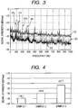
- Fig. 3 shows an example of a frequency analysis signal outputted from the above-described FFT unit 26.
- an abscissa indicates a frequency (Hz), and an ordinate represents a signal strength (dBVrms).
- a signal "S1" indicated by a solid line corresponds to a frequency analysis signal acquired in such a case that the hub unit 2 is a new product.
- a signal "S2" indicated by a broken line corresponds to a frequency analysis signal acquired in such a case that rust has occurred in the hub unit 2.
- a signal "S3" represented by a dot line corresponds to a frequency analysis signal acquired in such a case that false brinelling has occurred in the hub unit 2.
- symbol “1Fo” shows a signal strength of the signal "S3" at a basic frequency "fo", which is caused by that the outer ring 5 is vibrated since the balls 11 and 12 are rotated on the raceway surfaces 6 and 7 of the outer ring 5 when the shaft member 3 is rotated at a predetermined rotation number.
- the signal strength "1Fo” of the frequency analysis signal "S3" at the basic frequency "fo” when the above-described false brinelling has occurred is given as -21.7 (dBVrms). This sample “3” corresponds to such a sample in the case that the false brinelling has occurred in the hub unit 2.
- a sample “2" is a sample in such a case that rust has occurred in the hub unit 2.
- a signal strength -29.9 (dBVrms) in this sample “2” indicates a signal strength of the signal "S2" shown in Fig. 3 at the basic frequency "fo.”
- a sample “1” corresponds to a sample in such a case that the hub unit 2 is a new product.
- a signal strength -34.7 (dBVrms) in this sample 1 indicates a signal strength of the signal S1 shown in Fig. 3 at the basic frequency "fo.”
- symbol “1Fi” shown in Fig. 3 represents a signal strength of the signal "S2" at a basic frequency “fi” which is caused by that the shaft member 3 is vibrated since the balls 11 and 12 are rotated on the raceway surfaces 8 and 9 of the shaft member 3 when the shaft member 3 is rotated at the above-described predetermined rotation number.
- symbol “2Fo” shown in Fig. 3 indicates such a signal strength of the signal “S3” at a frequency “2fo” which is two times higher than the above-described basic frequency “fo.”
- symbol “2Fi” shown in Fig. 3 indicates such a signal strength of the signal "S2" at a frequency "2fi” which is two times higher than the above-described basic frequency "fi.”
- the evaluation output unit 28 evaluates such a fact that the false brinelling has occurred on the raceway surfaces 6 and 7 of the outer ring 5, and then, outputs this evaluation to the above-described display unit 27.
- the evaluation output unit 28 evaluates such a fact that the false brinelling has occurred on the raceway surfaces 8 and 9 of the shaft member 3 and then, outputs this evaluation to the above-described display unit 27. It should also be noted that the evaluation output unit 28 may alternatively evaluate damage conditions as to the outer ring 5 and the shaft member 3 based upon the signal strengths of the frequencies "2fo” and “2fi” which are two times higher than the basic frequencies “fo” and "fi", instead of the signal strengths of the basic frequencies "fo” and "fi” in the above-described frequency analysis signals.
- the evaluation output unit 28 may alternatively evaluate damage conditions as to the outer ring 5 and the shaft member 3 based upon the signal strengths of the frequencies "2fo” and “2fi” which are two times higher than the basic frequencies “fo” and “fi”, and further, the signal strengths of the basic frequencies “fo” and “fi” in the frequency analysis signals.
- Fig. 5 indicates that an overall value of the frequency analysis signal "S3" in such a sample “1" that the hub unit 2 is a new product is equal to 2.3 (m/s 2 ), and an overall value of the frequency analysis signal “S2" in such a sample “2” that rust has occurred in the hub unit 2 is equal to 43.4 (m/s 2 ). Also, Fig. 5 indicates that an overall value of the frequency analysis signal "S3” in such a sample “3” that false brinelling has occurred in the hub unit 2 is equal to 6.0 (m/s 2 ). As can be understood from Fig. 5 , in such a case that the rust has occurred in the hub unit 2, the overall value of the frequency analysis signal "S2" becomes the largest value.
- the above-described evaluation output unit 28 evaluates that the rust has occurred in the hub unit 2 when an overall value of a frequency analysis signal entered from the FFT unit 26 exceeds a predetermined threshold value (20 (m/s 2 ) as one example), and then, outputs this evaluation result to the display unit 27.
- the evaluation output unit 28 evaluates that the hub unit 2 is a new product, or is a substantially new product, and then, outputs this evaluation result to the display unit 27.
- the evaluation apparatus of the hub unit is provided with a driven wheel driving unit 31 which is indicated by a dot and dash line in Fig. 1 .
- the driven wheel driving unit 31 contains an adaptor flange 31A and a motor (not shown) which rotatably drives the adapter flange 31A.
- the vehicle is jacked up so as to dismount both a wheel and a brake disk.
- the above-described motor is driven so as to rotate the adaptor flange 31A by which the shaft member 3 is rotated.
- the above-described hub unit 2 corresponds to a hub unit of a drive wheel, this drive wheel is put on a freely rotatable roller, and then, the wheel is rotated by an engine of a vehicle.
- the acceleration sensor 1 is fixed on the flat upper plane 17 of the hub bolt 15 by the magnet 18 by utilizing the magnetic force; the frequency of the output signal outputted from the acceleration sensor 1 is analyzed; and as previously explained, the damage condition of the hub unit 2 is evaluated based upon both the signal strength of the specific frequency and the overall value, which are acquired from the frequency analysis signal indicative of the frequency analysis result.
- the hub unit evaluation apparatus can judge whether or not damage has occurred in a hub unit in a quantitative manner, and also, can diagnose a failure of a hub unit under such a condition that the hub unit has been assembled in a vehicle. As a result, even a car dealer can diagnose the failure of the hub unit.
- the signal processing unit 23 has contained the A/D converting unit 24.
- the signal processing unit 23 may alternatively and directly input the output signal of the acceleration sensor 1 to the envelope detecting unit 25.
- the evaluation apparatus of the hub unit has been equipped with the evaluation output unit 28.
- a user may directly judge the damage condition of the hub unit 2 based upon both the frequency analysis signal and the overall value, which are exemplified in Fig. 3 , and are displayed on the display unit 27.
Description
- The present invention is related to an evaluation apparatus of a hub unit, and an evaluating method of the hub unit, which evaluates whether or not damage of the hub unit is present, and also, evaluates a sort of damage.
- Conventionally, an abnormal event detecting apparatus for a hub unit has been proposed (
JP-A-11-248524 - However, although the above-described abnormal event detecting apparatus for the hub unit is capable of detecting increases in temperatures which are caused by overloads given to bearings and deteriorations in bearings, this conventional abnormal event detecting apparatus cannot simply determine sorts of damage from each other made in the hub unit.
- On the other hand, it is required for such a hub unit abnormal event detecting apparatus capable of judging sorts of damage made in hub units in a simpler manner.
-
EP 1 548 419 A1 - As a consequence, an object of the present invention is to provide an evaluation apparatus of a hub unit, which can determine sorts of damage made in the hub unit from each other in a simple manner.
- To solve the above-described problem, an evaluation apparatus of a hub unit, according to the present invention, is featured by comprising the features of
claim 1. - In accordance with the above-described evaluation apparatus of the hub unit related to the present invention, the signal processing unit inputs the frequency analysis signal to the above-described output unit, while the frequency analysis signal contains both the signal strength of the specific frequency and the overall value, which represent such a result that the output signal of the acceleration sensor fixed on the hub unit by the magnetic force mounting unit is detected for an envelope detection, and then, a signal entered from the envelope detection is analyzed for a frequency analysis. Then, the output unit outputs the signal strength of the specific frequency and the overall value, which are contained in the above-explained frequency analysis signal, to a display unit, or the like.
- As a consequence, in accordance with the present invention, the output signal of the acceleration sensor is analyzed for the frequency analysis and with employment of the signal strength of the specific frequency and the overall value as to the frequency analysis signal produced by this frequency analysis, the sorts of damage of the hub unit can be determined from each other. Also, the acceleration sensor main body can be detachably mounted with respect to the fixing-sided member of the hub unit in a simple manner. Also, the driven wheel is rotated by the driven wheel driving unit in order to rotate the rotation-sided member of the hub unit of the driven wheel, so that an evaluation test for the above-described hub unit can be carried out. On the other hand, in such a case that an evaluation test for such a hub unit of a drive wheel is carried out, the drive wheel is rotated by a driving power source such as an engine, so that the evaluation test for the hub unit can be carried out.
- In accordance with the present invention, the output signal of the acceleration sensor is analyzed for the frequency analysis and with employment of the signal strength of the specific frequency and the overall value as to the frequency analysis signal produced by this frequency analysis, so that it is possible to judge whether or not the damage of the hub unit is present, and also the sorts of damage of the hub unit can be determined from each other in the simple manner.
-
-
Fig. 1 is a sectional view for showing such a condition that an acceleration sensor has been mounted on a hub unit, while an evaluation apparatus for a hub unit according to an embodiment of the present invention is equipped with the acceleration sensor. -
Fig. 2 is a block diagram for indicating an arrangement of the hub unit evaluation apparatus according to the present embodiment. -
Fig. 3 is a diagram for representing one example of frequency analysis signals outputted from an FFT unit employed in the present embodiment. -
Fig. 4 is a diagram for indicating signal strengths at a basic frequency "fo" in the frequency analysis signals "S1", "S2", "S3" ofFig. 3 . -
Fig. 5 is a diagram for showing overall values in the frequency analysis signals "S1", "S2", "S3" ofFig. 3 . - The present invention will now be described in detail with reference to illustrated embodiments.
-
Fig. 1 shows both anacceleration sensor 1 and ahub unit 2, which are provided by an embodiment as to an evaluation apparatus of a hub unit according to the present invention. The above-describedaccelerator sensor 1 is mounted on thehub unit 2. As shown inFig. 1 , thehub unit 2 is provided with ashaft member 3 corresponding to a rotation-sided member; anouter ring 5 corresponding to a fixing-sided member; plural rows ofballs cages balls balls raceway surfaces outer ring 5, andraceway surfaces shaft member 3. It should be noted that theraceway surface 9 of the above-describedshaft member 3 has been formed on aninner ring 3A provided by theshaft member 3. - The
outer ring 5 corresponding to the fixing-sided member of the above-describedhub unit 2 has aflange 16, while theflange 16 of theouter ring 5 has been fastened to aknuckle 36 by ahub bolt 15 meshed with ascrew hole 16A formed in thisflange 16. Then, amagnet 18 functioning as a magnetic force mounting unit has been fixed on a flatupper plane 17 of a head portion of the above-describedhub bolt 15 by utilizing magnetic force of themagnet 18. Anacceleration pickup 20 functioning as an acceleration sensor main body has been fixed on thismagnet 18. Both theacceleration pickup 20 and themagnet 18 have constructed the above-describedacceleration sensor 1. It should also be noted that the above-describedmagnet 18 may be alternatively fixed on either theknuckle 36 or theouter ring 5 instead of such a structure that the above-describedmagnet 18 is fixed on anupper plane 17 of thehub bolt 15 which fastens theouter ring 5. - A
signal line 21 of the above-describedacceleration sensor 1 has been connected to an A/D converting unit 24 of asignal processing unit 23 shown inFig. 2 . Thesignal processing unit 23 contains the A/D converting unit 24, anenvelope detecting unit 25, and an FFT unit (Fast Fourier Transformation unit) 26. The A/D converting unit 25 converts an analog signal entered from theacceleration sensor 1 into a digital signal. Theenvelope detecting unit 25 performs envelope detection with the digital signal entered from the A/D converting unit 24. TheFFT unit 26 functioning as a frequency analyzing unit for frequency analysis using fast Fourier transformation with an envelope detection signal entered from theenvelope detecting unit 25. - Also, both a
display unit 27 and anevaluation output unit 28 have been connected to the fast Fouriertransforming unit 26, which function as output units. A frequency analysis signal indicative of the above-described frequency analysis result is inputted from theFFT unit 26 into thedisplay unit 27, so that thedisplay unit 27 displays thereon this frequency analysis signal. Thedisplay unit 27 is constituted by a liquid crystal display panel as one example. It should also be noted that the above-describeddisplay unit 27 may be alternatively replaced by a printer which prints the frequency analysis signal. - On the other hand, the frequency analysis signal indicative of the above-described frequency analysis result is similarly inputted from the above-described
FFT unit 26 to the above-describedevaluation output unit 28. Thisevaluation output unit 28 evaluates a damage condition of thehub unit 2 based upon a signal strength of a specific frequency and an overall value, which are obtained from the above-described frequency analysis signal, and outputs the damage condition. - In this case,
Fig. 3 shows an example of a frequency analysis signal outputted from the above-describedFFT unit 26. InFig. 3 , an abscissa indicates a frequency (Hz), and an ordinate represents a signal strength (dBVrms). InFig. 3 , a signal "S1" indicated by a solid line corresponds to a frequency analysis signal acquired in such a case that thehub unit 2 is a new product. Also, a signal "S2" indicated by a broken line corresponds to a frequency analysis signal acquired in such a case that rust has occurred in thehub unit 2. Furthermore, a signal "S3" represented by a dot line corresponds to a frequency analysis signal acquired in such a case that false brinelling has occurred in thehub unit 2. - In
Fig. 3 , symbol "1Fo" shows a signal strength of the signal "S3" at a basic frequency "fo", which is caused by that theouter ring 5 is vibrated since theballs raceway surfaces outer ring 5 when theshaft member 3 is rotated at a predetermined rotation number. As shown as a sample "3" inFig. 4 , the signal strength "1Fo" of the frequency analysis signal "S3" at the basic frequency "fo" when the above-described false brinelling has occurred is given as -21.7 (dBVrms). This sample "3" corresponds to such a sample in the case that the false brinelling has occurred in thehub unit 2. - Also, in
Fig. 4 , a sample "2" is a sample in such a case that rust has occurred in thehub unit 2. A signal strength -29.9 (dBVrms) in this sample "2" indicates a signal strength of the signal "S2" shown inFig. 3 at the basic frequency "fo." Also, inFig. 4 , a sample "1" corresponds to a sample in such a case that thehub unit 2 is a new product. A signal strength -34.7 (dBVrms) in thissample 1 indicates a signal strength of the signal S1 shown inFig. 3 at the basic frequency "fo." - Also, symbol "1Fi" shown in
Fig. 3 represents a signal strength of the signal "S2" at a basic frequency "fi" which is caused by that theshaft member 3 is vibrated since theballs raceway surfaces shaft member 3 when theshaft member 3 is rotated at the above-described predetermined rotation number. Also, symbol "2Fo" shown inFig. 3 indicates such a signal strength of the signal "S3" at a frequency "2fo" which is two times higher than the above-described basic frequency "fo." Also, symbol "2Fi" shown inFig. 3 indicates such a signal strength of the signal "S2" at a frequency "2fi" which is two times higher than the above-described basic frequency "fi." - As a consequence, when a signal strength having the above-described basic frequency "fo" in a frequency analysis signal entered from the
FFT unit 26 exceeds a predetermined threshold value (as one example, -25 dVbrms), theevaluation output unit 28 evaluates such a fact that the false brinelling has occurred on theraceway surfaces outer ring 5, and then, outputs this evaluation to the above-describeddisplay unit 27. Also, when a signal strength having the above-described basic frequency "fi" in the above-described frequency analysis signal exceeds the predetermined threshold value, theevaluation output unit 28 evaluates such a fact that the false brinelling has occurred on the raceway surfaces 8 and 9 of theshaft member 3 and then, outputs this evaluation to the above-describeddisplay unit 27. It should also be noted that theevaluation output unit 28 may alternatively evaluate damage conditions as to theouter ring 5 and theshaft member 3 based upon the signal strengths of the frequencies "2fo" and "2fi" which are two times higher than the basic frequencies "fo" and "fi", instead of the signal strengths of the basic frequencies "fo" and "fi" in the above-described frequency analysis signals. Also, theevaluation output unit 28 may alternatively evaluate damage conditions as to theouter ring 5 and theshaft member 3 based upon the signal strengths of the frequencies "2fo" and "2fi" which are two times higher than the basic frequencies "fo" and "fi", and further, the signal strengths of the basic frequencies "fo" and "fi" in the frequency analysis signals. - Next,
Fig. 5 indicates that an overall value of the frequency analysis signal "S3" in such a sample "1" that thehub unit 2 is a new product is equal to 2.3 (m/s2), and an overall value of the frequency analysis signal "S2" in such a sample "2" that rust has occurred in thehub unit 2 is equal to 43.4 (m/s2). Also,Fig. 5 indicates that an overall value of the frequency analysis signal "S3" in such a sample "3" that false brinelling has occurred in thehub unit 2 is equal to 6.0 (m/s2). As can be understood fromFig. 5 , in such a case that the rust has occurred in thehub unit 2, the overall value of the frequency analysis signal "S2" becomes the largest value. - As a consequence, the above-described
evaluation output unit 28 evaluates that the rust has occurred in thehub unit 2 when an overall value of a frequency analysis signal entered from theFFT unit 26 exceeds a predetermined threshold value (20 (m/s2) as one example), and then, outputs this evaluation result to thedisplay unit 27. - Then, in such a case that an overall value of a frequency analysis signal entered from the above-described
FFT unit 26 becomes smaller than the predetermined threshold value, and further, signal strengths of the above-described frequency analysis signals having the basic frequencies "fi" and "fo", theevaluation output unit 28 evaluates that thehub unit 2 is a new product, or is a substantially new product, and then, outputs this evaluation result to thedisplay unit 27. - Also, the evaluation apparatus of the hub unit is provided with a driven
wheel driving unit 31 which is indicated by a dot and dash line inFig. 1 . The drivenwheel driving unit 31 contains anadaptor flange 31A and a motor (not shown) which rotatably drives theadapter flange 31A. Then, in such a case that the above-describedhub unit 2 corresponds to a hub unit of a driven wheel, the vehicle is jacked up so as to dismount both a wheel and a brake disk. Next, under such a condition that theadaptor flange 31A of the drivenwheel driving unit 31 indicated by a dot and dash line shown inFig. 1 has been contacted to theflange 3B of theshaft member 3 in a friction manner, the above-described motor is driven so as to rotate theadaptor flange 31A by which theshaft member 3 is rotated. On the other hand, in such a case that the above-describedhub unit 2 corresponds to a hub unit of a drive wheel, this drive wheel is put on a freely rotatable roller, and then, the wheel is rotated by an engine of a vehicle. - Then, the
acceleration sensor 1 is fixed on the flatupper plane 17 of thehub bolt 15 by themagnet 18 by utilizing the magnetic force; the frequency of the output signal outputted from theacceleration sensor 1 is analyzed; and as previously explained, the damage condition of thehub unit 2 is evaluated based upon both the signal strength of the specific frequency and the overall value, which are acquired from the frequency analysis signal indicative of the frequency analysis result. - In accordance with the present embodiment, the hub unit evaluation apparatus can judge whether or not damage has occurred in a hub unit in a quantitative manner, and also, can diagnose a failure of a hub unit under such a condition that the hub unit has been assembled in a vehicle. As a result, even a car dealer can diagnose the failure of the hub unit.
- It should also be understood that in the above-described embodiment, the
signal processing unit 23 has contained the A/D converting unit 24. Alternatively, thesignal processing unit 23 may alternatively and directly input the output signal of theacceleration sensor 1 to theenvelope detecting unit 25. Also, in the above-described embodiment, the evaluation apparatus of the hub unit has been equipped with theevaluation output unit 28. Alternatively, while such anevaluation output unit 28 is not employed, a user may directly judge the damage condition of thehub unit 2 based upon both the frequency analysis signal and the overall value, which are exemplified inFig. 3 , and are displayed on thedisplay unit 27.
Claims (1)
- An evaluation apparatus of a hub unit (2), comprising:an acceleration sensor (1) which is mounted on the hub unit (2); anda signal processing unit (23) which performs a frequency analysis with a signal entered from the acceleration sensor (1) when the hub unit (2) is rotated so as to acquire a signal strength of a specific frequency and an overall value in the signal,characterized by comprising:an evaluation output unit (28) adapted to compare the overall value with a first threshold value, and the signal strength with a second threshold value so as to determine that a condition of the hub unit (2) is one of a condition where the hub unit (2) is a new product, a condition where a rust has occurred in the hub unit (2), and a condition where a false brinelling has occurred on the hub unit (2), whereinthe evaluation output unit (28) is adapted to determine that the condition of the hub unit (2) is the condition where the rust has occurred in the hub unit (2) when the overall value exceeds the first threshold value,the evaluation output unit (28) is adapted to determine that the condition of the hub unit (2) is the condition where the false brinelling has occurred on the hub unit (2) when the signal strength exceeds the second threshold value, and the evaluation output unit (28) is adapted to determine that the condition of the hub unit (2) is the condition where the hub unit (2) is the new product when the overall value is equal to or smaller than the first threshold value, and the signal strength is equal to or smaller than the second threshold value.
Applications Claiming Priority (1)
| Application Number | Priority Date | Filing Date | Title |
|---|---|---|---|
| JP2007194629A JP5003331B2 (en) | 2007-07-26 | 2007-07-26 | Hub unit evaluation device and hub unit evaluation method |
Publications (3)
| Publication Number | Publication Date |
|---|---|
| EP2019304A2 EP2019304A2 (en) | 2009-01-28 |
| EP2019304A3 EP2019304A3 (en) | 2016-03-02 |
| EP2019304B1 true EP2019304B1 (en) | 2019-02-27 |
Family
ID=39743096
Family Applications (1)
| Application Number | Title | Priority Date | Filing Date |
|---|---|---|---|
| EP08013203.8A Expired - Fee Related EP2019304B1 (en) | 2007-07-26 | 2008-07-22 | Evaluation apparatus of hub unit and evaluating method of hub unit |
Country Status (3)
| Country | Link |
|---|---|
| US (1) | US7821950B2 (en) |
| EP (1) | EP2019304B1 (en) |
| JP (1) | JP5003331B2 (en) |
Families Citing this family (14)
| Publication number | Priority date | Publication date | Assignee | Title |
|---|---|---|---|---|
| JP2008268187A (en) * | 2007-03-26 | 2008-11-06 | Nippon Steel Corp | Method and device for diagnosing abnormality of extremely low speed rotary machine |
| JP5673382B2 (en) * | 2011-06-21 | 2015-02-18 | 日本精工株式会社 | Abnormal diagnosis method |
| JP2013257265A (en) * | 2012-06-14 | 2013-12-26 | Ntn Corp | Abnormality detection system of railroad vehicle bearing |
| EP2833115A4 (en) * | 2012-03-28 | 2015-11-11 | Ntn Toyo Bearing Co Ltd | Railroad vehicle bearing malfunction sensing system |
| WO2014090305A1 (en) * | 2012-12-12 | 2014-06-19 | Aktiebolaget Skf | Detecting irregularities in a rotation of roller bodies in a roller bearing |
| DE102013201324A1 (en) * | 2013-01-28 | 2014-07-31 | Aktiebolaget Skf | Device and method for determining a bearing preload |
| JP2014215164A (en) * | 2013-04-25 | 2014-11-17 | Ntn株式会社 | Vibration measuring unit and vibration measuring system using the same |
| AU2015314909B2 (en) | 2014-09-12 | 2018-08-02 | Hendrickson Usa, L.L.C. | Wheel end sensor for heavy-duty vehicles |
| CN104568442B (en) * | 2015-01-27 | 2018-03-02 | 贵州电力试验研究院 | A kind of method of adjustment of high power turbine generator bearing static state absolute altitude |
| US20180059656A1 (en) * | 2015-03-12 | 2018-03-01 | Hitachi, Ltd. | Machine Diagnostic Device and Machine Diagnostic Method |
| JP6734664B2 (en) * | 2016-02-25 | 2020-08-05 | 川崎重工業株式会社 | Bearing monitoring device for railway vehicles |
| JP6881133B2 (en) * | 2017-07-31 | 2021-06-02 | 日本精工株式会社 | Vibration measuring device for vacuum bearings |
| JP7136726B2 (en) * | 2019-03-11 | 2022-09-13 | 株式会社荏原製作所 | Signal processing device, signal processing method |
| KR102490084B1 (en) * | 2020-02-21 | 2023-01-19 | 주식회사 일진글로벌 | Defect diagnosis device for wheel bearing |
Family Cites Families (13)
| Publication number | Priority date | Publication date | Assignee | Title |
|---|---|---|---|---|
| JPS62151621A (en) | 1985-12-25 | 1987-07-06 | Anritsu Corp | Device for detecting abnormality in rolling bearing |
| WO1999005486A2 (en) * | 1997-07-22 | 1999-02-04 | Skf Condition Monitoring | Vibration monitoring system |
| JP3692234B2 (en) | 1998-03-05 | 2005-09-07 | 光洋精工株式会社 | Abnormality detection device for hub unit for large vehicles |
| JP3693867B2 (en) * | 1999-11-12 | 2005-09-14 | 本田技研工業株式会社 | Inspection method for vehicle behavior stabilization mechanism |
| JP2002340922A (en) * | 2001-01-25 | 2002-11-27 | Nsk Ltd | Rotation detector for wheel |
| WO2004027370A1 (en) * | 2002-08-30 | 2004-04-01 | Nsk Ltd. | Method and device for monitoring status of mechanical equipment and abnormality diagnosing device |
| JP2004257836A (en) * | 2003-02-25 | 2004-09-16 | Nsk Ltd | Abnormality diagnostic device of mechanical device |
| JP2004212225A (en) * | 2002-12-27 | 2004-07-29 | Nsk Ltd | Abnormality diagnostic apparatus |
| JP3864146B2 (en) * | 2003-03-18 | 2006-12-27 | 株式会社東芝 | Bearing diagnosis device for rotating machine, bearing diagnosis system for rotating machine, portable terminal and function expansion card |
| JP3944744B2 (en) * | 2003-07-29 | 2007-07-18 | 日本精工株式会社 | Abnormality diagnosis device and rolling bearing device having the same |
| US7860663B2 (en) * | 2004-09-13 | 2010-12-28 | Nsk Ltd. | Abnormality diagnosing apparatus and abnormality diagnosing method |
| JP4581860B2 (en) | 2005-01-26 | 2010-11-17 | 日本精工株式会社 | Machine equipment abnormality diagnosis apparatus and abnormality diagnosis method |
| WO2006043511A1 (en) * | 2004-10-18 | 2006-04-27 | Nsk Ltd. | Abnormality diagnosis system for machinery |
-
2007
- 2007-07-26 JP JP2007194629A patent/JP5003331B2/en active Active
-
2008
- 2008-07-22 EP EP08013203.8A patent/EP2019304B1/en not_active Expired - Fee Related
- 2008-07-24 US US12/219,586 patent/US7821950B2/en not_active Expired - Fee Related
Non-Patent Citations (1)
| Title |
|---|
| None * |
Also Published As
| Publication number | Publication date |
|---|---|
| EP2019304A2 (en) | 2009-01-28 |
| US7821950B2 (en) | 2010-10-26 |
| JP5003331B2 (en) | 2012-08-15 |
| EP2019304A3 (en) | 2016-03-02 |
| JP2009031100A (en) | 2009-02-12 |
| US20090040935A1 (en) | 2009-02-12 |
Similar Documents
| Publication | Publication Date | Title |
|---|---|---|
| EP2019304B1 (en) | Evaluation apparatus of hub unit and evaluating method of hub unit | |
| JP2009031100A5 (en) | ||
| US7860663B2 (en) | Abnormality diagnosing apparatus and abnormality diagnosing method | |
| JP5146008B2 (en) | Abnormality diagnosis apparatus and abnormality diagnosis method | |
| EP2522977B1 (en) | Abnormality diagnosis device for rolling bearing, wind power generator, and abnormality diagnosis system | |
| JP4560110B2 (en) | Abnormality diagnosis apparatus and abnormality diagnosis method | |
| JP4710455B2 (en) | Abnormality diagnosis device for axle support device of railway vehicle | |
| WO2004027370A1 (en) | Method and device for monitoring status of mechanical equipment and abnormality diagnosing device | |
| JP2005345277A (en) | Monitoring device and monitoring method | |
| KR102503857B1 (en) | Defect diagnosis device and wheel bearing for vehicle provided therewith | |
| JP2004257836A (en) | Abnormality diagnostic device of mechanical device | |
| JP2007278895A (en) | Device and method for diagnosing abnormality | |
| JP6714844B2 (en) | Abnormality diagnosis method | |
| JP5673382B2 (en) | Abnormal diagnosis method | |
| WO2018088564A1 (en) | Bearing abnormality diagnostic method and diagnostic system | |
| US11333577B2 (en) | Method and device for diagnosing abnormality in rolling bearing | |
| JP2019158514A (en) | Inspection device of bearing for passenger conveyor, and inspection method of bearing for passenger conveyor | |
| JP3918939B2 (en) | Machine equipment monitoring system | |
| JP2008102005A (en) | Abnormality diagnosis device | |
| KR20070105288A (en) | Bearing fault diagnosis for diesel engine generator using labview | |
| KR20220130054A (en) | Diagnosis device and diagnosis method for wheel bearing, and wheel bearing provided therewith | |
| US11900737B2 (en) | Failure diagnosis device for wheel bearing | |
| JP2004093357A (en) | Evaluation method and evaluation device | |
| JP4941030B2 (en) | Abnormality diagnosis device and bearing device provided with the same | |
| CN114646467B (en) | Driving motor bearing detection method suitable for whole vehicle environment |
Legal Events
| Date | Code | Title | Description |
|---|---|---|---|
| PUAI | Public reference made under article 153(3) epc to a published international application that has entered the european phase |
Free format text: ORIGINAL CODE: 0009012 |
|
| AK | Designated contracting states |
Kind code of ref document: A2 Designated state(s): AT BE BG CH CY CZ DE DK EE ES FI FR GB GR HR HU IE IS IT LI LT LU LV MC MT NL NO PL PT RO SE SI SK TR |
|
| AX | Request for extension of the european patent |
Extension state: AL BA MK RS |
|
| PUAL | Search report despatched |
Free format text: ORIGINAL CODE: 0009013 |
|
| AK | Designated contracting states |
Kind code of ref document: A3 Designated state(s): AT BE BG CH CY CZ DE DK EE ES FI FR GB GR HR HU IE IS IT LI LT LU LV MC MT NL NO PL PT RO SE SI SK TR |
|
| AX | Request for extension of the european patent |
Extension state: AL BA MK RS |
|
| RIC1 | Information provided on ipc code assigned before grant |
Ipc: G01M 13/04 20060101AFI20160128BHEP |
|
| 17P | Request for examination filed |
Effective date: 20160802 |
|
| RBV | Designated contracting states (corrected) |
Designated state(s): AT BE BG CH CY CZ DE DK EE ES FI FR GB GR HR HU IE IS IT LI LT LU LV MC MT NL NO PL PT RO SE SI SK TR |
|
| AKX | Designation fees paid |
Designated state(s): DE FR |
|
| AXX | Extension fees paid |
Extension state: BA Extension state: RS Extension state: MK Extension state: AL |
|
| 17Q | First examination report despatched |
Effective date: 20180412 |
|
| GRAP | Despatch of communication of intention to grant a patent |
Free format text: ORIGINAL CODE: EPIDOSNIGR1 |
|
| INTG | Intention to grant announced |
Effective date: 20181011 |
|
| GRAS | Grant fee paid |
Free format text: ORIGINAL CODE: EPIDOSNIGR3 |
|
| GRAA | (expected) grant |
Free format text: ORIGINAL CODE: 0009210 |
|
| AK | Designated contracting states |
Kind code of ref document: B1 Designated state(s): DE FR |
|
| REG | Reference to a national code |
Ref country code: DE Ref legal event code: R096 Ref document number: 602008059101 Country of ref document: DE |
|
| REG | Reference to a national code |
Ref country code: DE Ref legal event code: R097 Ref document number: 602008059101 Country of ref document: DE |
|
| PLBE | No opposition filed within time limit |
Free format text: ORIGINAL CODE: 0009261 |
|
| STAA | Information on the status of an ep patent application or granted ep patent |
Free format text: STATUS: NO OPPOSITION FILED WITHIN TIME LIMIT |
|
| 26N | No opposition filed |
Effective date: 20191128 |
|
| PG25 | Lapsed in a contracting state [announced via postgrant information from national office to epo] |
Ref country code: FR Free format text: LAPSE BECAUSE OF NON-PAYMENT OF DUE FEES Effective date: 20190731 |
|
| PGFP | Annual fee paid to national office [announced via postgrant information from national office to epo] |
Ref country code: DE Payment date: 20200707 Year of fee payment: 13 |
|
| REG | Reference to a national code |
Ref country code: DE Ref legal event code: R119 Ref document number: 602008059101 Country of ref document: DE |
|
| PG25 | Lapsed in a contracting state [announced via postgrant information from national office to epo] |
Ref country code: DE Free format text: LAPSE BECAUSE OF NON-PAYMENT OF DUE FEES Effective date: 20220201 |