EP2019182A2 - System zur Luftabdichtung von Ecken in Gebäuden - Google Patents
System zur Luftabdichtung von Ecken in Gebäuden Download PDFInfo
- Publication number
- EP2019182A2 EP2019182A2 EP20080159308 EP08159308A EP2019182A2 EP 2019182 A2 EP2019182 A2 EP 2019182A2 EP 20080159308 EP20080159308 EP 20080159308 EP 08159308 A EP08159308 A EP 08159308A EP 2019182 A2 EP2019182 A2 EP 2019182A2
- Authority
- EP
- European Patent Office
- Prior art keywords
- film
- cover element
- intersection
- portions
- point
- Prior art date
- Legal status (The legal status is an assumption and is not a legal conclusion. Google has not performed a legal analysis and makes no representation as to the accuracy of the status listed.)
- Withdrawn
Links
Images




Classifications
-
- E—FIXED CONSTRUCTIONS
- E04—BUILDING
- E04B—GENERAL BUILDING CONSTRUCTIONS; WALLS, e.g. PARTITIONS; ROOFS; FLOORS; CEILINGS; INSULATION OR OTHER PROTECTION OF BUILDINGS
- E04B1/00—Constructions in general; Structures which are not restricted either to walls, e.g. partitions, or floors or ceilings or roofs
- E04B1/62—Insulation or other protection; Elements or use of specified material therefor
- E04B1/66—Sealings
-
- E—FIXED CONSTRUCTIONS
- E04—BUILDING
- E04D—ROOF COVERINGS; SKY-LIGHTS; GUTTERS; ROOF-WORKING TOOLS
- E04D1/00—Roof covering by making use of tiles, slates, shingles, or other small roofing elements
- E04D1/36—Devices for sealing the spaces or joints between roof-covering elements
-
- E—FIXED CONSTRUCTIONS
- E06—DOORS, WINDOWS, SHUTTERS, OR ROLLER BLINDS IN GENERAL; LADDERS
- E06B—FIXED OR MOVABLE CLOSURES FOR OPENINGS IN BUILDINGS, VEHICLES, FENCES OR LIKE ENCLOSURES IN GENERAL, e.g. DOORS, WINDOWS, BLINDS, GATES
- E06B1/00—Border constructions of openings in walls, floors, or ceilings; Frames to be rigidly mounted in such openings
- E06B1/62—Tightening or covering joints between the border of openings and the frame or between contiguous frames
-
- E—FIXED CONSTRUCTIONS
- E06—DOORS, WINDOWS, SHUTTERS, OR ROLLER BLINDS IN GENERAL; LADDERS
- E06B—FIXED OR MOVABLE CLOSURES FOR OPENINGS IN BUILDINGS, VEHICLES, FENCES OR LIKE ENCLOSURES IN GENERAL, e.g. DOORS, WINDOWS, BLINDS, GATES
- E06B1/00—Border constructions of openings in walls, floors, or ceilings; Frames to be rigidly mounted in such openings
- E06B1/70—Sills; Thresholds
- E06B1/702—Window sills
-
- E—FIXED CONSTRUCTIONS
- E06—DOORS, WINDOWS, SHUTTERS, OR ROLLER BLINDS IN GENERAL; LADDERS
- E06B—FIXED OR MOVABLE CLOSURES FOR OPENINGS IN BUILDINGS, VEHICLES, FENCES OR LIKE ENCLOSURES IN GENERAL, e.g. DOORS, WINDOWS, BLINDS, GATES
- E06B1/00—Border constructions of openings in walls, floors, or ceilings; Frames to be rigidly mounted in such openings
- E06B1/62—Tightening or covering joints between the border of openings and the frame or between contiguous frames
- E06B2001/628—Separate flexible joint covering strips; Flashings
Definitions
- the present invention relates to a system for air sealing of leaks in building corners.
- US 4 700 512 For exterior sealing for the purpose of preventing intrusion of water in a building foundation and for the provision of a wind shield, one solution is disclosed in US 4 700 512 .
- the document discloses a flexible membrane adapted for exterior sealing of a masonry building foundation. Yet, the membrane allows passage of air, admitting dehydration of the humidity that is naturally found in the building.
- Another solution to the same problem is found in US 6 401 401 B1 , disclosing a molded three-dimensional plastics geometry adapted to be mounted against a building corner on the exterior side of a wall portion.
- the present invention relates however to interior sealing of buildings and more precisely air sealing of building corners with the purpose of creating an airtight vapour retarder/vapour barrier on the interior side of the building for improved energy consumption by reduced energy losses and controlled ventilation.
- Massive concrete walls and plastered brick walls largely consist of inorganic material which is not particularly sensitive to moisture. Moreover they are in most cases very airtight and resist moisture very well, and therefore no additional air sealing with a separate vapour barrier or vapour retarder is usually considered necessary.
- the stud walls are provided with a diffusion- and airtight inside and a diffusion-open, windproof and rainproof outside.
- the diffusion and air seal consists of an airtight film with vapour retarder or vapour barrier properties and can be made of, for example, plastic film, aluminium foil, impregnated kraft paper or laminates of these materials. Laminates, if any, can be provided with a reinforcing carrier layer.
- US 5 243 787 discloses a simple method which is intended for solutions in which the window frame and the wall are positioned in the same plane.
- the diffusion and air sealing film is, according to the method, first stretched across the window, after which two diagonal cuts are made in the film so that four triangular flaps are formed. These flaps are then folded away from the window portion and fastened to the walls.
- the above solution cannot be used.
- the same method as described above that is the diffusion and air sealing film is stretched across the window and two diagonal cuts are made in the film so as to form four triangular flaps. Subsequently these flaps are folded into the window bay and fastened to its walls, after which residual material in the tips of the flaps is removed.
- this method there is however no diffusion and air sealing film in the corners, in the following referred to as building corners, at the basis of the flaps.
- these portions below referred to as leaks, are left without diffusion seal, resulting in zones that are not tight adjacent the windows with the risk of damage due to moisture, resulting in a great loss of energy.
- these building corners are, however, sealed by means of pieces of diffusion and air sealing film.
- the leaks in the film that arise in any of these positions are usually sealed with adhesive tape, sealing strip or jointing material and pieces of film.
- adhesive tape or sealing strip is attached along and frequently over an edge, which means that the originally two-dimensional tape/strip must be folded to follow the three-dimensional extent. This requires precision and patience and often tends to result in undesirable wrinkling.
- the greatest problem occurs at the point P at which three surfaces in the building corner coincide and easily several overlapping layers of adhesive tape are required. If the worst comes to the worst, this can result in difficulties in the subsequent mounting of cover panels and surface layers.
- An object of the present invention is to provide a cover element to be used for air sealing of leaks in building corners.
- cover element should be a complete and simple solution that is quick and easy to mount.
- a further object of the invention is that it should be easy to adjust the cover element to building corners that are not right-angled and to different depths of the building corners.
- the present invention relates to a system for air sealing of leaks in building corners in a wall portion made up of a framework, comprising a cover element comprising at least two flexible film portions of an airtight film with vapour retarder or vapour barrier properties, which are interconnected along rim portions by means of linear weld joints, linear fold lines being arranged in said film portions to allow folding of the cover element to form a three-dimensional geometry consisting of three surfaces which meet at a point of intersection, and a diffusion and air sealing film attached to the wall portion, the three-dimensionally folded cover element being adapted to be fastened to said diffusion and air sealing film in said building corners for air sealing of said leeks.
- building corner refers throughout in the following to structures in which at least three surfaces coincide so as to form a corner.
- leak refers to defects, such as gaps, cracks, lead-throughs and incomplete overlappings in a surface that is intended to be airtight.
- the inventive cover element can be provided in the form of a two-dimensional, essentially plane geometry, which makes it easy and cheap to distribute and handle up to mounting in which it is unfolded in one simple operation to form a three-dimensional geometry which directly or with simple cutting/folding can be mounted in a building corner.
- the mounting of the cover element is simple since, when in its folded three-dimensional state, it forms large, essentially flat surfaces which can be arranged over and seal the leaks that arise when cutting and folding the diffusion and air sealing film which is initially mounted over the stud wall and the building corner.
- the time consuming and trying work of cutting and mounting extra pieces across the leaks can thus be eliminated.
- the only complementary work that is required is adjusting the cover element to the depth of the building corner in question and taping up the rim portions of the cover element to the surrounding surfaces with diffusion and air sealing film.
- This work is quick and easy since all surfaces are large, flat and easy to reach. This increases the quality of the sealing work, which in turn greatly reduces the risk of deficient and careless sealing, resulting in a risk of, for instance, damage due to moisture and energy loss.
- the design of the cover element is simple, which allows easy and inexpensive production. Moreover, one and the same size of the cover element can be provided and used since, in connection with mounting, the cover element can easily be adjusted to the depth of the building corner in question or to a building corner that is possibly not right-angled.
- the depth of the building corner can, for example, vary depending on the type and age of the building, building specifications, the make and type of the window/door.
- the cover element can easily, by being made of flexible film, be provided with new fold lines so as to fit in the building corner in question.
- At least two of the weld joints can start from said point of intersection.
- at least two of the fold lines can start from said point of intersection.
- both said fold lines and said weld joints can start from said point of intersection.
- the point of intersection forms the corner in which the three surfaces coincide when folding the cover element to its three-dimensional geometry.
- the fold lines and the weld joints act to make up the surfaces to form essentially flat surfaces of the three-dimensional geometry.
- the three-dimensional folding can be arranged to occur by folding along at least four lines. At least two of the fold lines may consist of said weld joints. By letting the weld joints form fold lines, the number of fold lines can be reduced, which facilitates manufacture but also the folding of the cover element to its three-dimensional geometry.
- the three surfaces forming the three-dimensional geometry may be three mutually orthogonal surfaces. This allows the cover element to be directly mounted in a right-angled building corner without adjustment by means of supplementary fold lines. The only adjustment that may be necessary is fitting the size of the surfaces depending on the depth of the building corner in question and desirable overlapping of the surrounding diffusion and air sealing film.
- the flexible film portion may consist of an airtight vapour retarder material or a vapour barrier material, which is the same type of material as is normally used in the diffusion and air sealing films that are available on the market. This means that the fitter can quite easily use the same types of adhesive tapes, sealing compounds and the like as are already at his disposal for other sealing work. Furthermore, the properties of the final diffusion seal are not affected since no new type of material is added.
- Said diffusion and air sealing film can have vapour retarder or vapour barrier properties.
- Said cover element can comprise portions provided with adhesive along at least some of the rim portions of the three-dimensionally folded cover element.
- Said cover element can have an oversized length of the parts of the rim portions which are adapted to be oriented toward the building corner during mounting.
- the cover element may comprise two film portions, which each have a geometry comprising a trapezoid which is provided with a right-angled corner and which changes into a right-angled quadrangle to form a straight first rim portion and an opposite angular second rim portion, the second rim portion comprising two weld joints which connect the two film portions and which meet at said point of intersection which is arranged along said second rim portion in the transition between the quadrangle and the trapezoid, and each film portion having a linear fold line which extends between the first and the second rim portion from the point of intersection, whereby two of the three surfaces, in folding to form said three-dimensional geometry, are formed by said right-angled quadrangle and the third surface is formed by said trapezoid by folding along said angular second rim portion and said linear fold lines.
- This embodiment of the cover element is very simple in its design since it is made of two identical, overlapping film portions which are interconnected along a rim portion, which allows very simple and inexpensive manufacture.
- the cover element may comprise a first film portion in the form of a right-angled quadrangle folded in two and a second film portion which in its state folded in two has a trapezoid form provided with a right-angled corner, said first and second film portions being interconnected along two weld joints to form together a straight first rim portion and an opposite angular second rim portion, the fold lines of the first and the second film portion being joined at the point of intersection to form said second rim portion, and said weld joints extending between said first and second rim portions from the point of intersection, whereby two of the three surfaces, in folding to form said three-dimensional geometry, are formed by said right-angled quadrangle and the third surface is formed by said trapezoid by folding along said second rim portion and said weld joints.
- the cover element may comprise a first film portion in the form of a first right-angled quadrangle, which by means of three fold lines and a slit is divided into four quadrants, which meet at a point of intersection, and a second film portion in the form of a right-angled triangle folded in two along the hypotenuse, the second film portion being, along two of its legs, connected by welding to the first film portion along both edges of said slit, whereby said legs coincide with the fold lines of the first film portion at the point of intersection, and whereby two of the three surfaces, in folding to form said three-dimensional geometry, are formed by two of said quadrants and the third surface is formed by the remaining two quadrants and said triangle three-dimensionally folded along the hypotenuse.
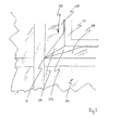
- FIG. 1 an example of a wall portion 100 in which a window is mounted 101 is shown highly schematically. No ventilation gap and no facing are shown.
- the wall portion 100 is made up of a framework 102 consisting of, for example, wood studs, forming a stud wall 103.
- the actual window 101 is fixedly mounted in the stud wall 103 by the frame of the window 101 being fixedly mounted in the surrounding studs.
- a diffusion and air sealing film 104 is attached to the stud wall 103.
- the diffusion and air sealing film 104 is folded in.
- the diffusion and air sealing film 104 has vapour retarder or vapour barrier properties and can be made of, for example, plastic film, aluminium foil, kraft paper or laminates of one of these materials. Laminates, if any, can be provided with a reinforcing carrier layer.
- the stud wall 103 is further insulated with an insulating material 106 which is arranged in the framework 102.
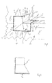
- the diffusion and air sealing film 104 In mounting the diffusion and air sealing film 104, this is usually attached to the stud wall 103 and the window 101 mounted therein, after which two diagonal cuts 107 are made in the film so that four triangular flaps 108 are formed, see Fig. 2 .
- the flaps 108 are then folded into the window bay and the building corners 105 and attached to the walls thereof, after which residual material in the tips of the flaps is removed, see Fig. 3 .
- this method there is, however, no diffusion and air sealing film 104 in the building corners 105 at the basis of the flaps, resulting in leaks 109 where moisture can enter and heat can escape.
- These leaks 109 are usually sealed according to prior art technique by means of pieces of diffusion and air sealing film, adhesive tape, sealing strip or jointing material.
- Sealing often occurs very arbitrarily since there are no standards and guide lines and no completed sealing elements either. Furthermore the work often occurs against the clock, which in itself often results in insufficient sealing. Finally, the inside of walls, window bay etc is cladded with material in the form of, for example, paper-coated gypsum boards, borders, panels or other wall lining, which in itself makes inspection of the sealing work very difficult.
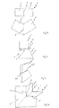
- a cover element 1 according to the present invention will be described with reference to Figs 4a-4d where the two-dimensional and three-dimensional geometries of the inventive cover element are shown.
- the inventive cover element is in fact adapted to be provided as a two-dimensional geometry which in connection with mounting is folded to form a three-dimensional geometry.
- the cover element 1 comprises in its two-dimensional geometry, see Fig. 4a , two identical flexible film portions 2 which are arranged one on top of the other.
- each film portion 2 can, with reference to Figs 4a-4c , geometrically seen be divided into a trapezoid 3 provided with a right-angled corner and changing into a right-angled quadrangle 4. More specifically, the trapezoid 3 changes into the right-angled quadrangle 4 along the shorter of the two parallel sides of the trapezoid.
- the two film portions 2 are interconnected by means of seam welding along the angular second rim portion 6.
- the weld can be divided into two linear weld joints 7 which both extend along the angular second rim portion 6 from a point of intersection P.
- the point of intersection P is arranged along the second rim portion in the transition between the right-angled quadrangle 4 and the angular side of the trapezoid 3.
- the cover element 1 comprises four linear fold lines 8, see Fig. 4c , which all start from the point of intersection P, of which two are pure fold lines 9 and two are formed by said weld joints 7.
- the two pure fold lines 9, which are arranged in the respective film portions 2, extend across the cover element between the first 5 and the second 6 rim portion from the point of intersection P, that is along the transition between the right-angled quadrangle 4 and the trapezoid 3. In the shown embodiment, these two fold lines 9 intersect the first rim portion 5 at right angles ⁇ .
- the purpose of the four fold lines 7, 8, 9 is to allow folding of the cover element from a two-dimensional to a three-dimensional geometry.
- the cover element is adapted to be provided in its two-dimensional geometry and then, in connection with mounting in a building corner, be folded to form a three-dimensional geometry by folding along the fold lines, see Fig. 4d .
- the cover element 1 forms in its folded, three-dimensional geometry three interconnected, essentially flat surfaces a, b, c which meet at the point of intersection P.
- the point of intersection P is to be found in the centre of the three-dimensionally folded cover element 1.
- Two of the surfaces a, b are formed by the two right-angled quadrangles 4, while the third surface c is formed together by the two trapezoids 3.
- the cover element 1 is adapted to be mounted in a building corner 105 in such a manner that three of the four fold lines 7, 8 9 are arranged over the edges of the building corner 105, while the fourth fold line 8 which consists of a weld joint 7 is arranged along the plane of the surrounding wall.
- the two surfaces a, b which are formed by the right-angled quadrangles 4 will thus cover the previously discussed leaks 109 which are formed in cutting and folding of the diffusion and air sealing film 104.
- the three surfaces a, b, c that are obtained in the folded three-dimensional geometry of the cover element 1 can be caused to form three mutually orthogonal surfaces that meet at the point of intersection P, see Fig. 4d so as to directly fit in a right-angled building corner.
- the angle ⁇ is chosen to be 135°.
- the angle ⁇ can be adjusted in such a manner that the cover element fits in non-right-angled building corners. It will also be understood that the angle ⁇ between the pure fold lines 9 and the first rim portion 5 can be adjusted according to the angles of a building corner. This can take place either by the cover element being provided with fold lines with preselected, predetermined angles ⁇ and ⁇ , or by the fitter in connection with mounting arranging fold lines on his own for adjusting the geometry to the building corner in question.
- the cover element 1 should overlap the posteriorly situated diffusion and air sealing film 104 in connection with mounting in a building corner 105.
- This overlap should be somewhere between 100 mm and 450 mm, see Fig. 5 .
- This overlap is obtained with the length X, Y of the rim portions of the film portions.
- the cover element can advantageously be provided with an oversized length of the parts of the rim portions which are adapted to be oriented towards the building corner during mounting, whereby the length can be adjusted by the fitter during mounting in dependence on the depth of the building corner.
- this may, as shown in Figs 5 and 6 , comprise portions 10 provided with adhesive along all or some of the rim portions of the three-dimensionally folded cover element.
- an adhesive can be arranged over the entire inner surface of the cover element.
- the portions provided with adhesive are advantageously coated with a protective film (not shown), which is torn off in connection with mounting.
- the rim portions which in the three-dimensionally folded state of the cover element are adapted to be oriented towards the building corner can be left without adhesive if the length of the these rim portions in accordance with the discussion above is oversized to allow adjustment to the depth of the building corner in question.
- cover element can also be provided without adhesive and instead be attached to the posteriorly situated diffusion and air sealing film by means of adhesive tape, sealing strip, jointing material or the like. It will further be appreciated that the inventive cover element should be supplemented with adhesive tape, jointing material or the like in the innermost part of the building corner.
- the flexible film portions 2 advantageously consist of an airtight film with vapour retarder or vapour barrier properties and can be made of, for instance, plastic film, aluminium foil, kraft paper or laminates of these materials. Laminates, if any, can be provided with a reinforcing carrier layer of, for example, glass fibre.
- the cover element is advantageously made of the same material as the surrounding diffusion and air sealing film. A typical thickness of this type of film is about 0.2 mm. In the case where a laminate is used, this can have a thickness, for instance, in the range 0.15-0.30 mm. However, it will be appreciated that this is an example only.
- FIGs 7a-7d an alternative embodiment of a cover element 1' according to the invention is illustrated. This embodiment differs from the one first described by the way in which the flexible film portions are configured and joined to form the above described two-dimensional geometry in the form of a "boot".
- the two-dimensional geometry is here created by two flexible film portions 2'.
- the first film portion is a right-angled quadrangle 4' folded in two.
- the second film portion is also folded in two and forms in its state folded in two a trapezoid 3' provided with a right-angled corner.
- the two film portions 2' are interconnected along two weld joints 7' in order to together form a straight first rim portion 5' and an opposite angular second rim portion 6'. More specifically, the two film portions 2' are joined along the shorter of the two parallel sides of the trapezoid 3'. As a result, the fold lines 9' of the first and the second film portion 2' will meet at the point of intersection P and together form the second rim portion 6'.
- the two weld joints 7' extend between the first 5' and second rim portions 6' from the point of intersection P. In the embodiment illustrated, the weld joints 7' extend at right angles ⁇ to the first rim portion 5'. The weld joints 7' also form fold lines 8'.
- the cover element 1' forms in its folded three-dimensional geometry, see Fig. 7d , three interconnected surfaces a', b', c' which meet at the point of intersection P, which in the three-dimensional geometry is to be found in the centre of the three-dimensionally folded cover element 1'.
- Two of the surfaces a', b' are formed by the three-dimensionally folded right-angled quadrangle 4' while the third surface 3' is formed by the three-dimensionally folded trapezoid 3'.
- the three-dimensional folding of the cover element 1' thus occurs along the angular second rim portion 6' and the two weld joints 7'.
- FIGs 8a-8d another alternative embodiment of a cover element 1" according to the invention is shown.
- the two-dimensional geometry is here too created by two flexible film portions 20", 21 ", see Fig. 8a .
- the first film portion 20" consists of a first right-angled quadrangle 4" which comprises three linear fold lines 9" which meet at right angles at the point of intersection P in the centre of the surface of the quadrangle.
- the point of intersection P can be arranged, for example, in the centre of the quadrangle.
- the first film portion 20" comprises a straight slit 11 which extends at right angles from a rim portion to the point of intersection P.
- the slit 11 and the three fold lines 9" together divide the first film portion 20" into four quadrants d 1 -d 4 .
- the second film portion 21" has the form of a right-angled triangle 13 folded in two along the hypotenuse 12.
- the first and the second film portion 20", 21 " are interconnected by seam welding by the legs 14 of the second film portion 21" being welded each to one side of the slit 11 of the first film portion 20", see Fig. 8b .
- One of the fold lines 9" of the quadrangle 4" meets at the point of intersection P the fold line which is arranged along the hypotenuse 12 of the second film portion 12" folded in two in order to form the above described angular second rim portion 6".
- the other two fold lines 9" of the quadrangle 4" extend between the first 5" and the second rim portion 6" from the point of intersection P at right angles ⁇ to the first rim portion 5". All fold lines 9" and weld lines 7" thus meet, in accordance with previous embodiments, at the point of intersection P.
- the cover element 1" When folding the cover element 1" from its two-dimensional geometry to its three-dimensional geometry, three-dimensional folding takes place along the fold lines 9" of the first film portion 20" and the fold line arranged along the hypotenuse 12 of the second film portion 21" folded in two.
- the two surfaces a", b" of the three-dimensional geometry will be formed by two quadrants d 1 ,d 2 of the first film portion 20".
- the third surface c" will be formed by the remaining two quadrants d 3 ,d 4 of the first film portion 20" together with the three-dimensionally folded second film portion 21".
- the cover element 1" forms in its folded three-dimensional geometry three interconnected surfaces a"-c" which meet at the point of intersection P which is to be found in the centre of the cover element 1".
- weld lines 7" do not form fold lines in this embodiment.
- angles ⁇ and ⁇ can in the second and third embodiments be varied to adjust the cover element to non-orthogonal building corners.
- Figs 9a and 9b illustrate highly schematically two such embodiments of a cover element 1 which is folded to form a three-dimensional geometry.
- the cover element is formed by a first film portion 2 and a second film portion 20.
- the first film portion 2 is folded along a fold line 8.
- the second film portion 20 is by welding joined to the first film portion 2 to form, together with this, a surface A. More specifically, the second film portion 20 forms a surface segment Aa.
- the first film portion 2 thus forms the surfaces B and C and together with the second film portion 20 the surface A. All three surfaces A, B, C meet at the point of intersection P.
- FIG. 9c Another variant is shown in Fig. 9c , in which a first 2 and a second film portion 20 are welded together to form three surfaces A, B, C which in the three-dimensionally folded state of the cover element 1 meet at the point of intersection P.
- the respective surfaces A, B, C can consist of separate welded together film portions.
Landscapes
- Engineering & Computer Science (AREA)
- Civil Engineering (AREA)
- Structural Engineering (AREA)
- Architecture (AREA)
- Physics & Mathematics (AREA)
- Electromagnetism (AREA)
- Building Environments (AREA)
Applications Claiming Priority (1)
| Application Number | Priority Date | Filing Date | Title |
|---|---|---|---|
| SE0701572A SE532823C2 (sv) | 2007-06-29 | 2007-06-29 | System innehållande täckelement för lufttätning i bygghörn |
Publications (2)
| Publication Number | Publication Date |
|---|---|
| EP2019182A2 true EP2019182A2 (de) | 2009-01-28 |
| EP2019182A3 EP2019182A3 (de) | 2012-10-17 |
Family
ID=40092102
Family Applications (1)
| Application Number | Title | Priority Date | Filing Date |
|---|---|---|---|
| EP20080159308 Withdrawn EP2019182A3 (de) | 2007-06-29 | 2008-06-30 | System zur Luftabdichtung von Ecken in Gebäuden |
Country Status (2)
| Country | Link |
|---|---|
| EP (1) | EP2019182A3 (de) |
| SE (1) | SE532823C2 (de) |
Cited By (4)
| Publication number | Priority date | Publication date | Assignee | Title |
|---|---|---|---|---|
| WO2013085872A1 (en) * | 2011-12-09 | 2013-06-13 | 3M Innovative Properties Company | Window frame wrapping system |
| WO2023178373A1 (de) | 2022-03-25 | 2023-09-28 | Burghart Michael | Klebeecke |
| EP4365400A1 (de) * | 2022-11-07 | 2024-05-08 | Funke Kunststoffe GmbH | Sockelabdichtung auf einer ebene, und fensteranordnung |
| EP4556669A1 (de) * | 2023-11-16 | 2025-05-21 | Funke Kunststoffe GmbH | Sockelabdichtung mit mehreren dichtungszonen, und fensteranordnung |
Citations (3)
| Publication number | Priority date | Publication date | Assignee | Title |
|---|---|---|---|---|
| US4700512A (en) | 1986-07-21 | 1987-10-20 | Laska Walter A | Corner flashing membrane |
| US5243787A (en) | 1992-12-28 | 1993-09-14 | Owens-Corning Fiberglas Technology, Inc. | Method of manufacture and use of a multi-function wrap |
| US6401401B1 (en) | 2000-10-20 | 2002-06-11 | Mark F. Williams | Multi-component flashing systems |
Family Cites Families (1)
| Publication number | Priority date | Publication date | Assignee | Title |
|---|---|---|---|---|
| WO2001071142A1 (en) * | 2000-03-22 | 2001-09-27 | Exterior Research And Design, L.L.C. | Window seal construction |
-
2007
- 2007-06-29 SE SE0701572A patent/SE532823C2/sv not_active IP Right Cessation
-
2008
- 2008-06-30 EP EP20080159308 patent/EP2019182A3/de not_active Withdrawn
Patent Citations (3)
| Publication number | Priority date | Publication date | Assignee | Title |
|---|---|---|---|---|
| US4700512A (en) | 1986-07-21 | 1987-10-20 | Laska Walter A | Corner flashing membrane |
| US5243787A (en) | 1992-12-28 | 1993-09-14 | Owens-Corning Fiberglas Technology, Inc. | Method of manufacture and use of a multi-function wrap |
| US6401401B1 (en) | 2000-10-20 | 2002-06-11 | Mark F. Williams | Multi-component flashing systems |
Cited By (4)
| Publication number | Priority date | Publication date | Assignee | Title |
|---|---|---|---|---|
| WO2013085872A1 (en) * | 2011-12-09 | 2013-06-13 | 3M Innovative Properties Company | Window frame wrapping system |
| WO2023178373A1 (de) | 2022-03-25 | 2023-09-28 | Burghart Michael | Klebeecke |
| EP4365400A1 (de) * | 2022-11-07 | 2024-05-08 | Funke Kunststoffe GmbH | Sockelabdichtung auf einer ebene, und fensteranordnung |
| EP4556669A1 (de) * | 2023-11-16 | 2025-05-21 | Funke Kunststoffe GmbH | Sockelabdichtung mit mehreren dichtungszonen, und fensteranordnung |
Also Published As
| Publication number | Publication date |
|---|---|
| EP2019182A3 (de) | 2012-10-17 |
| SE0701572L (sv) | 2008-12-30 |
| SE532823C2 (sv) | 2010-04-20 |
Similar Documents
| Publication | Publication Date | Title |
|---|---|---|
| US9016017B2 (en) | System and cover element for air sealing | |
| EP2193249B1 (de) | Selbsthaftende, dehn- und faltbare Eckabdeckung für Gebäude | |
| US20150047269A1 (en) | Method for flashing a window or door opening | |
| ES2985128T3 (es) | Elemento de conexión de la costura de malla | |
| CN101529040A (zh) | 用于建筑物开口的阻挡组件 | |
| US20170051553A1 (en) | Sill pan | |
| EP2019182A2 (de) | System zur Luftabdichtung von Ecken in Gebäuden | |
| WO2006066034A2 (en) | Self-adhered flange for use with non-flanged windows | |
| EP3513015B1 (de) | Verfahren für scharnierte trockenwand | |
| WO2018062275A1 (ja) | 外壁の防水構造、外壁パネルおよび外壁パネルの防水施工方法 | |
| KR102005470B1 (ko) | 버블시트를 이용한 갱폼 개구 차단 구조 | |
| JP6319639B2 (ja) | サッシ廻りの気密構造 | |
| ES2932300T3 (es) | Un panel de madera compuesto sin desperdicios y sin cortes para la construcción de edificios de maderaje de madera | |
| JP6900238B2 (ja) | 建具 | |
| US11028290B2 (en) | Heat-applied gap finishing tape | |
| JP7088648B2 (ja) | 断熱構造、および断熱構造の施工方法 | |
| US20250137251A1 (en) | Hinging drywall apparatus and method | |
| FI123601B (fi) | Seinärakenne ja menetelmä seinärakenteen valmistamiseksi | |
| JP7387287B2 (ja) | 断熱構造体、及び板状断熱材 | |
| NO348490B1 (en) | Sealing sleeve and method for sealing in wet rooms | |
| JP2005179958A (ja) | 建築物の気密構造、及びそれからなる建築物 | |
| JP2004225446A (ja) | 断熱材目地部の構造 | |
| JP2026017805A (ja) | 中空ガスケットと中空ガスケット付きパネル、及び、十字状交差部の目地構造とt字状交差部の目地構造 | |
| GB2405651A (en) | Extension for creating lead - through in cast material | |
| IES20100234A2 (en) | A ground membrane system |
Legal Events
| Date | Code | Title | Description |
|---|---|---|---|
| PUAI | Public reference made under article 153(3) epc to a published international application that has entered the european phase |
Free format text: ORIGINAL CODE: 0009012 |
|
| 17P | Request for examination filed |
Effective date: 20080630 |
|
| AK | Designated contracting states |
Kind code of ref document: A2 Designated state(s): AT BE BG CH CY CZ DE DK EE ES FI FR GB GR HR HU IE IS IT LI LT LU LV MC MT NL NO PL PT RO SE SI SK TR |
|
| AX | Request for extension of the european patent |
Extension state: AL BA MK RS |
|
| PUAL | Search report despatched |
Free format text: ORIGINAL CODE: 0009013 |
|
| AK | Designated contracting states |
Kind code of ref document: A3 Designated state(s): AT BE BG CH CY CZ DE DK EE ES FI FR GB GR HR HU IE IS IT LI LT LU LV MC MT NL NO PL PT RO SE SI SK TR |
|
| AX | Request for extension of the european patent |
Extension state: AL BA MK RS |
|
| RIC1 | Information provided on ipc code assigned before grant |
Ipc: E06B 1/62 20060101AFI20120912BHEP |
|
| AKX | Designation fees paid |
Designated state(s): AT BE BG CH CY CZ DE DK EE ES FI FR GB GR HR HU IE IS IT LI LT LU LV MC MT NL NO PL PT RO SE SI SK TR |
|
| 17Q | First examination report despatched |
Effective date: 20150317 |
|
| STAA | Information on the status of an ep patent application or granted ep patent |
Free format text: STATUS: THE APPLICATION IS DEEMED TO BE WITHDRAWN |
|
| 18D | Application deemed to be withdrawn |
Effective date: 20160531 |