EP2019180B1 - Betriebsvorrichtung für Fenster - Google Patents
Betriebsvorrichtung für Fenster Download PDFInfo
- Publication number
- EP2019180B1 EP2019180B1 EP20080160950 EP08160950A EP2019180B1 EP 2019180 B1 EP2019180 B1 EP 2019180B1 EP 20080160950 EP20080160950 EP 20080160950 EP 08160950 A EP08160950 A EP 08160950A EP 2019180 B1 EP2019180 B1 EP 2019180B1
- Authority
- EP
- European Patent Office
- Prior art keywords
- window
- rack
- locking device
- actuator
- pinion
- Prior art date
- Legal status (The legal status is an assumption and is not a legal conclusion. Google has not performed a legal analysis and makes no representation as to the accuracy of the status listed.)
- Not-in-force
Links
- 230000033001 locomotion Effects 0.000 description 10
- 238000005273 aeration Methods 0.000 description 1
- 230000005540 biological transmission Effects 0.000 description 1
- 230000008878 coupling Effects 0.000 description 1
- 238000010168 coupling process Methods 0.000 description 1
- 238000005859 coupling reaction Methods 0.000 description 1
- 230000002452 interceptive effect Effects 0.000 description 1
- 239000002184 metal Substances 0.000 description 1
Images


Classifications
-
- E—FIXED CONSTRUCTIONS
- E05—LOCKS; KEYS; WINDOW OR DOOR FITTINGS; SAFES
- E05F—DEVICES FOR MOVING WINGS INTO OPEN OR CLOSED POSITION; CHECKS FOR WINGS; WING FITTINGS NOT OTHERWISE PROVIDED FOR, CONCERNED WITH THE FUNCTIONING OF THE WING
- E05F11/00—Man-operated mechanisms for operating wings, including those which also operate the fastening
- E05F11/02—Man-operated mechanisms for operating wings, including those which also operate the fastening for wings in general, e.g. fanlights
- E05F11/04—Man-operated mechanisms for operating wings, including those which also operate the fastening for wings in general, e.g. fanlights with cords, chains or cables
- E05F11/06—Man-operated mechanisms for operating wings, including those which also operate the fastening for wings in general, e.g. fanlights with cords, chains or cables in guide-channels
-
- E—FIXED CONSTRUCTIONS
- E05—LOCKS; KEYS; WINDOW OR DOOR FITTINGS; SAFES
- E05C—BOLTS OR FASTENING DEVICES FOR WINGS, SPECIALLY FOR DOORS OR WINDOWS
- E05C9/00—Arrangements of simultaneously actuated bolts or other securing devices at well-separated positions on the same wing
- E05C9/04—Arrangements of simultaneously actuated bolts or other securing devices at well-separated positions on the same wing with two sliding bars moved in opposite directions when fastening or unfastening
- E05C9/041—Arrangements of simultaneously actuated bolts or other securing devices at well-separated positions on the same wing with two sliding bars moved in opposite directions when fastening or unfastening with rack and pinion mechanism
-
- E—FIXED CONSTRUCTIONS
- E05—LOCKS; KEYS; WINDOW OR DOOR FITTINGS; SAFES
- E05C—BOLTS OR FASTENING DEVICES FOR WINGS, SPECIALLY FOR DOORS OR WINDOWS
- E05C9/00—Arrangements of simultaneously actuated bolts or other securing devices at well-separated positions on the same wing
- E05C9/04—Arrangements of simultaneously actuated bolts or other securing devices at well-separated positions on the same wing with two sliding bars moved in opposite directions when fastening or unfastening
- E05C9/046—Arrangements of simultaneously actuated bolts or other securing devices at well-separated positions on the same wing with two sliding bars moved in opposite directions when fastening or unfastening with two interconnected mechanisms each driving one rod
-
- E—FIXED CONSTRUCTIONS
- E05—LOCKS; KEYS; WINDOW OR DOOR FITTINGS; SAFES
- E05F—DEVICES FOR MOVING WINGS INTO OPEN OR CLOSED POSITION; CHECKS FOR WINGS; WING FITTINGS NOT OTHERWISE PROVIDED FOR, CONCERNED WITH THE FUNCTIONING OF THE WING
- E05F15/00—Power-operated mechanisms for wings
- E05F15/60—Power-operated mechanisms for wings using electrical actuators
- E05F15/603—Power-operated mechanisms for wings using electrical actuators using rotary electromotors
- E05F15/611—Power-operated mechanisms for wings using electrical actuators using rotary electromotors for swinging wings
- E05F15/616—Power-operated mechanisms for wings using electrical actuators using rotary electromotors for swinging wings operated by push-pull mechanisms
-
- E—FIXED CONSTRUCTIONS
- E05—LOCKS; KEYS; WINDOW OR DOOR FITTINGS; SAFES
- E05B—LOCKS; ACCESSORIES THEREFOR; HANDCUFFS
- E05B47/00—Operating or controlling locks or other fastening devices by electric or magnetic means
- E05B47/0001—Operating or controlling locks or other fastening devices by electric or magnetic means with electric actuators; Constructional features thereof
- E05B2047/0014—Constructional features of actuators or power transmissions therefor
- E05B2047/0015—Output elements of actuators
- E05B2047/0016—Output elements of actuators with linearly reciprocating motion
-
- E—FIXED CONSTRUCTIONS
- E05—LOCKS; KEYS; WINDOW OR DOOR FITTINGS; SAFES
- E05B—LOCKS; ACCESSORIES THEREFOR; HANDCUFFS
- E05B47/00—Operating or controlling locks or other fastening devices by electric or magnetic means
- E05B47/0001—Operating or controlling locks or other fastening devices by electric or magnetic means with electric actuators; Constructional features thereof
- E05B47/0012—Operating or controlling locks or other fastening devices by electric or magnetic means with electric actuators; Constructional features thereof with rotary electromotors
-
- E—FIXED CONSTRUCTIONS
- E05—LOCKS; KEYS; WINDOW OR DOOR FITTINGS; SAFES
- E05B—LOCKS; ACCESSORIES THEREFOR; HANDCUFFS
- E05B53/00—Operation or control of locks by mechanical transmissions, e.g. from a distance
- E05B53/003—Operation or control of locks by mechanical transmissions, e.g. from a distance flexible
-
- E—FIXED CONSTRUCTIONS
- E05—LOCKS; KEYS; WINDOW OR DOOR FITTINGS; SAFES
- E05Y—INDEXING SCHEME ASSOCIATED WITH SUBCLASSES E05D AND E05F, RELATING TO CONSTRUCTION ELEMENTS, ELECTRIC CONTROL, POWER SUPPLY, POWER SIGNAL OR TRANSMISSION, USER INTERFACES, MOUNTING OR COUPLING, DETAILS, ACCESSORIES, AUXILIARY OPERATIONS NOT OTHERWISE PROVIDED FOR, APPLICATION THEREOF
- E05Y2201/00—Constructional elements; Accessories therefor
- E05Y2201/20—Brakes; Disengaging means; Holders; Stops; Valves; Accessories therefor
- E05Y2201/218—Holders
- E05Y2201/22—Locks
-
- E—FIXED CONSTRUCTIONS
- E05—LOCKS; KEYS; WINDOW OR DOOR FITTINGS; SAFES
- E05Y—INDEXING SCHEME ASSOCIATED WITH SUBCLASSES E05D AND E05F, RELATING TO CONSTRUCTION ELEMENTS, ELECTRIC CONTROL, POWER SUPPLY, POWER SIGNAL OR TRANSMISSION, USER INTERFACES, MOUNTING OR COUPLING, DETAILS, ACCESSORIES, AUXILIARY OPERATIONS NOT OTHERWISE PROVIDED FOR, APPLICATION THEREOF
- E05Y2201/00—Constructional elements; Accessories therefor
- E05Y2201/20—Brakes; Disengaging means; Holders; Stops; Valves; Accessories therefor
- E05Y2201/23—Actuation thereof
- E05Y2201/232—Actuation thereof by automatically acting means
- E05Y2201/24—Actuation thereof by automatically acting means using lost motion
-
- E—FIXED CONSTRUCTIONS
- E05—LOCKS; KEYS; WINDOW OR DOOR FITTINGS; SAFES
- E05Y—INDEXING SCHEME ASSOCIATED WITH SUBCLASSES E05D AND E05F, RELATING TO CONSTRUCTION ELEMENTS, ELECTRIC CONTROL, POWER SUPPLY, POWER SIGNAL OR TRANSMISSION, USER INTERFACES, MOUNTING OR COUPLING, DETAILS, ACCESSORIES, AUXILIARY OPERATIONS NOT OTHERWISE PROVIDED FOR, APPLICATION THEREOF
- E05Y2201/00—Constructional elements; Accessories therefor
- E05Y2201/40—Motors; Magnets; Springs; Weights; Accessories therefor
- E05Y2201/43—Motors
- E05Y2201/434—Electromotors; Details thereof
-
- E—FIXED CONSTRUCTIONS
- E05—LOCKS; KEYS; WINDOW OR DOOR FITTINGS; SAFES
- E05Y—INDEXING SCHEME ASSOCIATED WITH SUBCLASSES E05D AND E05F, RELATING TO CONSTRUCTION ELEMENTS, ELECTRIC CONTROL, POWER SUPPLY, POWER SIGNAL OR TRANSMISSION, USER INTERFACES, MOUNTING OR COUPLING, DETAILS, ACCESSORIES, AUXILIARY OPERATIONS NOT OTHERWISE PROVIDED FOR, APPLICATION THEREOF
- E05Y2201/00—Constructional elements; Accessories therefor
- E05Y2201/60—Suspension or transmission members; Accessories therefor
- E05Y2201/622—Suspension or transmission members elements
- E05Y2201/644—Flexible elongated pulling elements
- E05Y2201/656—Chains
-
- E—FIXED CONSTRUCTIONS
- E05—LOCKS; KEYS; WINDOW OR DOOR FITTINGS; SAFES
- E05Y—INDEXING SCHEME ASSOCIATED WITH SUBCLASSES E05D AND E05F, RELATING TO CONSTRUCTION ELEMENTS, ELECTRIC CONTROL, POWER SUPPLY, POWER SIGNAL OR TRANSMISSION, USER INTERFACES, MOUNTING OR COUPLING, DETAILS, ACCESSORIES, AUXILIARY OPERATIONS NOT OTHERWISE PROVIDED FOR, APPLICATION THEREOF
- E05Y2201/00—Constructional elements; Accessories therefor
- E05Y2201/60—Suspension or transmission members; Accessories therefor
- E05Y2201/622—Suspension or transmission members elements
- E05Y2201/71—Toothed gearing
- E05Y2201/722—Racks
- E05Y2201/724—Flexible
-
- E—FIXED CONSTRUCTIONS
- E05—LOCKS; KEYS; WINDOW OR DOOR FITTINGS; SAFES
- E05Y—INDEXING SCHEME ASSOCIATED WITH SUBCLASSES E05D AND E05F, RELATING TO CONSTRUCTION ELEMENTS, ELECTRIC CONTROL, POWER SUPPLY, POWER SIGNAL OR TRANSMISSION, USER INTERFACES, MOUNTING OR COUPLING, DETAILS, ACCESSORIES, AUXILIARY OPERATIONS NOT OTHERWISE PROVIDED FOR, APPLICATION THEREOF
- E05Y2900/00—Application of doors, windows, wings or fittings thereof
- E05Y2900/10—Application of doors, windows, wings or fittings thereof for buildings or parts thereof
- E05Y2900/13—Type of wing
- E05Y2900/148—Windows
Definitions
- This invention relates to an operating device for windows.
- Awning windows comprise a mobile frame or sash that opens outwards from the bottom and is hinged at the top to a fixed window frame.
- Prior art windows be they of the traditional type (opened by turning), bottom-hung or top-hung are equipped with suitable locking devices which prevent the window from being opened.
- these locking devices keep the window closed at two or more fastening points, in addition to the traditional fastening point located half way along the width of the frame (the latter being normally the case in bottom-hung windows and top-hung, awning windows).
- the locking device is normally mounted on the mobile frame and comprises one or more rods each provided with at least one pin and/or boss (protruding from the end of the rod in the case of the pin or transversally of the rod in the case of the boss) designed to engage or release a respective contact member formed or mounted on the fixed frame.
- the rods are slidable in a groove running along the edge of at least one side of the mobile frame, usually the side opposite the hinged side.
- the locking device is engaged and disengaged by an operating device (handle) used to open and close the window.
- the window cannot be opened.
- the locking device is disengaged, on the other hand, the mobile frame can be moved away from the fixed frame.
- the operating device comprises a control element, which may be either manual (handle) or power driven, and which controls the drive means that can be associated with the locking device.
- the control element is usually power-driven.
- the power-driven control element comprises a power unit with an electric motor that drives a flexible actuator, such as a chain, or an electromechanical actuator, such as a rigid rod that slides in a cylinder.
- the power unit is usually associated with the fixed part of the frame, while the actuator, connected to the motor at one end, acts on the mobile part of the frame with its other end, exerting a pushing or pulling force that respectively opens or closes the window, which is guided, normally by a pair of hinges and, where necessary, also by guiding arms interposed between the upright members of the mobile frame and those of the fixed frame.
- the actuator operates on the drive means which lock and unlock the mobile frame to and from the fixed frame.
- the drive means comprise a linkage connected to one or two rods for engaging and disengaging the above mentioned boss.
- Also known are operating devices comprising drive means that have excessively complex structures or do not guarantee a satisfactory level of precision in driving the locking device.
- awning windows cannot be equipped with power-driven operating devices having special linkages for obtaining multiple closures of the type described above, and the systems and units currently used on bottom-hung windows cannot be adapted to suit top-hung, awning windows.
- This invention therefore has for an aim to overcome the above mentioned disadvantages by providing an operating device for windows, in particular for power-driven awning windows.
- Another aim of the invention is to provide an operating device for windows, which can be adapted to suit bottom-hung windows and which is small enough, even during operation, to be mounted on thin mobile frames.
- a further aim of the invention is to provide an operating device for windows which improves the mechanism for transmitting drive from the power unit to the locking device and which guarantees a better level of precision in opening and closing the window.
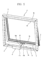
- the numeral 1 denotes an operating device 1 for single-sash hinged windows of the type illustrated in Figures 5 and 6 .
- This specification and the accompanying drawings illustrate an "awning" type window.
- Windows 2 of this type comprise a mobile frame 3 hinged to a fixed frame 4 along one respective first side 3a, 4a (horizontal members).
- the hinged side is the upper horizontal member and the sash or mobile frame 3 opens outwards from the bottom.
- Windows of this kind are used mainly in high-rise buildings with glazed curtain walls to allow good aeration of the interior while at the same time limiting the extent to which the windows themselves can be opened, primarily for security reasons.
- At least one second side 3b (lower horizontal member) of the mobile frame 3 moves away from a second side 4b of the fixed frame 4, as shown in Figure 5 , while in the closed configuration of the window 2 ( Figure 6 ), the second side 3b of the mobile frame 3 is in contact with the second side 4b of the fixed frame 4.
- the second side 3b, 4b of the frames is generally opposite and parallel to the first side 3a, 4a (in other words, as stated, they are the two horizontal members of the window unit).
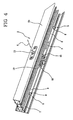
- the operating device 1 is usually associated with the mobile frame 3 which usually comprises a profile made of metal or plastic (such as PVC), a detail of which is shown in Figure 4 .
- PVC metal or plastic
- the window unit 2 may advantageously be locked in the closed configuration to improve the weather seal or to prevent breaking in.
- the window units are normally provided with locking devices 5 which identify further closing points of the window unit 2.
- the operating device 1 is associated with the locking device 5 to engage or disengage it or, in other words, to move it between a configuration where the window unit 2 is locked and the mobile frame 3 is engaged with the fixed frame 4, and a configuration where the window unit 2 is unlocked and the mobile frame 3 is disengaged from the fixed frame 4, allowing the window unit 2 to be opened.
- the locking device 5 may comprise one or more rods 6 slidable in a groove 7 made in the second side 3b of the mobile frame 3 and one or more fastening elements 8 fixed near a free end 6a of the rod 6.
- the fastening elements 8 are bosses which, in the locked configuration of the window unit 2, engage a respective contact element 9 made on the fixed frame 4.
- the contact element 9 is embodied, for example, by the walls of a housing socket, rigidly formed on the fixed frame 4 of the window, which define a contact shoulder, or the walls of a part associated with the fixed frame itself.
- the bosses engage the respective sockets, interfering with the related contact element 9 and thus preventing the mobile frame 3 from being moved away from the fixed frame 4.
- the bosses are disengaged from the sockets, in such a way as to lie outside of them, thus enabling the mobile frame 3 to be moved away from the fixed frame 4 to open the window.
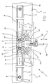
- the operating device 1 according to the invention, illustrated in Figures 1 to 4 , comprises drive means 10, described in detail below, which are housed in a mounting block 10a located inside the mobile frame 3, and which can be associated with the locking device 5, for reversibly moving the locking device 5 between the locked configuration and the unlocked configuration of the window.
- drive means 10 described in detail below, which are housed in a mounting block 10a located inside the mobile frame 3, and which can be associated with the locking device 5, for reversibly moving the locking device 5 between the locked configuration and the unlocked configuration of the window.
- the drive means 10 are linked to a control element 11, preferably power-driven, as shown in Figure 5 .
- the control element 11 comprises a box-shaped body 11a housing a power unit of customary type and therefore not illustrated (such as an electric motor, for example) and an actuator 12 controlled by the power unit.
- the actuator 12 may be of electromechanical type, such as, for example, a rigid sliding rod or a hinged rod, or of flexible type, such as a chain actuator.
- the actuator is embodied by a chain that is unwound to enable the window unit 2 to be opened.
- the chain actuator 12 is wound inside the box-shaped body 11a.
- the power unit is permanently associated with the fixed frame 4, while the actuator 12 has a first end 12a for connection with the power unit, and a second end 12b through which the actuator 12 operates on the mobile frame 3.
- the power unit unwinds and rewinds the actuator 12 to open and close the window 2, respectively.
- the drive means 10 Interposed between the locking device 5 and the control element 11 are the drive means 10.
- the latter comprise a rack 13 operatively associated with the control element 11, and at least one pinion 14 that meshes with the rack 13.
- the pinion 14 is hinged to the mounting block 10a and is rotatable about an axis 14a transversal to the rods 6 of the locking device 5.
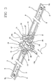
- the drive means 10 also comprise a system 15 for connecting the pinion 14 to the locking device 5 so as to transmit the motion of the rack 13 to the locking device 5 to move the latter from the locked to the unlocked configuration and vice versa.
- the connecting system 15 comprises a protrusion 16, integral with the pinion 14 and having a slot 17 inside which a pin 18 is inserted.
- the pin 18 is in turn connected to the locking device 5; more specifically, the pin 18 is fixed to a slider 19 that is directly fixed to the rod 6 of the locking device 5.
- the rack 13 is two-sided, that is to say, has two opposite toothed profiles 20.
- the drive means 10 preferably comprise two pinions 14, each meshing with a respective toothed profile 20 of the rack 13, and each being hinged to the mounting block 10a and rotatable about a respective axis 14a transversal to the rods 6 of the locking device 5.
- the window 2 must be opened in two steps, during the first of which it is unlocked by moving the actuator through a distance defined as the "overtravel" of the actuator, and during the second of which the window is moved to the open position proper.
- the power unit activates the actuator 12, and in this particular embodiment, unwinds the chain, which advances at right angles to the mobile frame 3 along a straight path T.
- the actuator 12 pushes the rack 13 and causes it to move in the same direction along the path T, that is to say, along the axis 13a of the rack 13 itself.
- the straight-line movement of the rack 13 is converted into the rotational movement of the pinions 14 which in turn cause the protrusion 16 to rotate.
- the pinions 14 turn in opposite directions about respective parallel axes, causing the protrusions 16 to move away from the axis 13a of the rack 13.
- the rotation of the protrusions 16 causes the pins 18 associated with them to move away from the axis 13a of the rack 13 along a straight path S transversal to the path T.
- the rods 6 also move away from the axis 13a of the rack 13, thereby displacing the bosses 8 and disengaging them from the respective contact elements 9 and thus releasing the window frame 4.
- the power unit again activates the actuator 12, but this time rewinding it inside the box-shaped body 11a.
- the actuator 12 exerts a tractive force on the mobile frame 3, pulling it towards the fixed frame 4 in such a way as to close the window 2.
- the rack 13 does not mesh with the pinions 14 and does not perform any movement relative to other parts of the operating device 1 but is pulled along as one with the rest of the operating device 1.
- the actuator 12 continues its movement, dragging the rack 13 along with it for a short distance, defined as its "overtravel", while the mobile frame 3 remains stationary.
- the rack 13 moves relative to the other parts of the operating device 1 in a straight line along the path T in the direction opposite to the previous direction, that is to say, it withdraws in such a way as to move the mobile frame 3 close to the fixed frame 4.
- the rack 13 meshes with the pinions 14 causing them to turn in the direction opposite to the previous direction.
- the protrusions 16 are also made to rotate accordingly, thereby causing the pins 18 to move in a straight line along the path S towards the axis 13a of the rack 13.
- the rack and pinion coupling mechanism creates an extremely "sturdy" system that appreciably reduces the possibility of forcibly reversing the stable open and closed positions adopted by the system.
- the operating device according to the invention can also be applied to bottom-hung windows.
Landscapes
- Engineering & Computer Science (AREA)
- Mechanical Engineering (AREA)
- Power-Operated Mechanisms For Wings (AREA)
- Lock And Its Accessories (AREA)
- Massaging Devices (AREA)
Claims (10)
- Betriebsvorrichtung (1) für Fenster, umfassend mindestens:- Antriebsmittel (10), die mit einer Verriegelungsvorrichtung (5) eines Fensters (2) verbunden werden können, um die Verriegelungsvorrichtung (5) zwischen einer verriegelten Stellung und einer unverriegelten Stellung des Fensters (2) zu bewegen;- ein Steuerelement (11), das auf die Antriebsmittel (10) entlang eines geraden Wegs (T) wirkt, um das Fenster (2) zu öffnen und zu schließen;
wobei die Vorrichtung dadurch gekennzeichnet ist, dass die Antriebsmittel (10) eine Zahnstange (13), betriebswirksam mit dem Steuerelement (11) verbunden, das entlang des geraden Wegs (T) verschoben werden kann, mindestens ein Ritzel (14), das in der Lage ist, in Eingriff mit der Zahnstange (13) zu gelangen, und ein System (15) für die Verbindung des Ritzels mit der Verriegelungsvorrichtung (5) umfassen, um die Verriegelungsvorrichtung (5) des Fensters (2) von einer verriegelten in eine unverriegelte Stellung und umgekehrt zu bewegen;
wobei das Verbindungssystem (15) einen Vorsprung (16) umfasst, fest verbunden mit dem Ritzel (14) und besitzend einen Schlitz (17), in dem ein Zapfen (18), verbunden mit der Verriegelungsvorrichtung (5), eingesetzt ist; der Zapfen (18) ist, der Drehung des Vorsprungs (16) folgend, entlang eines geraden Wegs (S), transversal zum von der Zahnstange (13) verfolgten Weg, bewegbar. - Vorrichtung (1) nach Anspruch 1, dadurch gekennzeichnet, dass der Zapfen (18) an einem Gleitstück (19) befestigt ist, verbunden mit der Verriegelungsvorrichtung (5).
- Vorrichtung (1) nach einem der Ansprüche 1 bis 2, dadurch gekennzeichnet, dass die Verriegelungsvorrichtung (5) mindestens eine Stange (6) umfasst, besitzend mindestens ein Befestigungselement (8), das mit einem Kontaktelement (9), ausgebildet auf dem Fenster (2), in Eingriff gelangen kann.
- Vorrichtung (1) nach Anspruch 2 und 3, dadurch gekennzeichnet, dass das Gleitstück (19) an der Stange (6) befestigt ist, wobei die Stange (6) schiebbar in einer Nut (7) untergebracht ist, ausgebildet an einer zweiten Seite (3b) eines beweglichen Rahmens (3) des Fensters (2), um die Verriegelungsvorrichtung (5) durch Eingreifen/Lösen des Befestigungselements (8) in das/aus dem Kontaktelement (9) zu verriegeln/entriegeln.
- Vorrichtung (1) nach einem der vorhergehenden Ansprüche, dadurch gekennzeichnet, dass die Zahnstange zwei gegenständige gezahnte Profile (20) besitzt, wobei die Antriebsmittel (10) zwei Ritzel (14) umfassen, von denen jedes in ein entsprechendes gezahntes Profil (20) der Zahnstange (13) eingreift.
- Vorrichtung (1) nach Anspruch 5, dadurch gekennzeichnet, dass jedes Ritzel (14) mit einer jeweiligen Verriegelungsvorrichtung (5) des Fensters (2) an gegenständigen Seiten der Zahnstange (13) verbunden werden kann.
- Vorrichtung (1) nach einem der vorhergehenden Ansprüche, dadurch gekennzeichnet, dass mindestens ein Ritzel (14) mit einem Montageblock (10a), untergebracht im beweglichen Rahmen (3), verknüpft ist, wobei mindestens ein Ritzel (14) um eine Drehachse (14a) an rechten Winkeln der Zahnstange (13) drehbar ist.
- Vorrichtung (1) nach einem der vorhergehenden Ansprüche, dadurch gekennzeichnet, dass das Steuerelement (11) eine Antriebseinheit und ein Aktuator (12), angetrieben von der Antriebseinheit, umfasst, wobei der Antrieb (12) die Zahnstange (13) bewegt.
- Vorrichtung (1) nach Anspruch 8, dadurch gekennzeichnet, dass der Aktuator (12) ein Kettentyp-Aktuator ist.
- Vorrichtung (1) nach Anspruch 8, dadurch gekennzeichnet, dass der Aktuator (12) ein elektromechanischer Aktuator ist.
Applications Claiming Priority (1)
| Application Number | Priority Date | Filing Date | Title |
|---|---|---|---|
| ITBO20070522 ITBO20070522A1 (it) | 2007-07-26 | 2007-07-26 | Dispositivo di manovra per infissi. |
Publications (3)
| Publication Number | Publication Date |
|---|---|
| EP2019180A2 EP2019180A2 (de) | 2009-01-28 |
| EP2019180A3 EP2019180A3 (de) | 2010-12-01 |
| EP2019180B1 true EP2019180B1 (de) | 2012-09-12 |
Family
ID=39800540
Family Applications (1)
| Application Number | Title | Priority Date | Filing Date |
|---|---|---|---|
| EP20080160950 Not-in-force EP2019180B1 (de) | 2007-07-26 | 2008-07-23 | Betriebsvorrichtung für Fenster |
Country Status (2)
| Country | Link |
|---|---|
| EP (1) | EP2019180B1 (de) |
| IT (1) | ITBO20070522A1 (de) |
Families Citing this family (7)
| Publication number | Priority date | Publication date | Assignee | Title |
|---|---|---|---|---|
| IT1398838B1 (it) * | 2010-03-19 | 2013-03-21 | Ultraflex Control Systems Srl | Sistema di attuazione dell'apertura e chiusura di ante |
| EP2730731B1 (de) * | 2012-11-09 | 2016-02-03 | Pentair Technical Solutions GmbH | Stangenschloss für Elektronikschränke |
| BE1021688B1 (fr) | 2013-05-28 | 2016-01-08 | Agc Glass Europe | Vitrage coulissant. |
| FR3008649B1 (fr) * | 2013-07-18 | 2015-08-07 | Acs France Sas | Dispositif d'obturation d'une baie d'un vehicule automobile a panneau coulissant, a poignee mobile parallelement a l'axe de coulissement et roues dentees, et vehicule correspondant. |
| DE102013110428A1 (de) * | 2013-09-20 | 2015-03-26 | Phoenix Contact Gmbh & Co. Kg | Elektromechanische Verriegelungsvorrichtung |
| WO2016136173A1 (ja) * | 2015-02-24 | 2016-09-01 | 八千代工業株式会社 | スライドパネル用ロック装置 |
| DE102018120280A1 (de) * | 2018-08-21 | 2020-02-27 | Martin Reuter | xRauchabzugseinrichtung |
Family Cites Families (4)
| Publication number | Priority date | Publication date | Assignee | Title |
|---|---|---|---|---|
| US5620216A (en) * | 1992-10-30 | 1997-04-15 | Fuller; Mark W. | Lock mechanism |
| DK172426B1 (da) * | 1996-02-12 | 1998-06-08 | Rasmussen Kann Ind As | Vindue med en paskvillåsemekanisme og en vinduesoperator med et udstillerelement |
| GB0016854D0 (en) * | 2000-07-11 | 2000-08-30 | Apw Electronics Ltd | Door latching mechanism |
| CH696245A5 (de) * | 2003-01-29 | 2007-02-28 | Rbs Beschlaege Gmbh | Ausstellvorrichtung eines Flügels, insbesondere für Fenster oder Lüftungseinrichtungen. |
-
2007
- 2007-07-26 IT ITBO20070522 patent/ITBO20070522A1/it unknown
-
2008
- 2008-07-23 EP EP20080160950 patent/EP2019180B1/de not_active Not-in-force
Also Published As
| Publication number | Publication date |
|---|---|
| ITBO20070522A1 (it) | 2009-01-27 |
| EP2019180A2 (de) | 2009-01-28 |
| EP2019180A3 (de) | 2010-12-01 |
Similar Documents
| Publication | Publication Date | Title |
|---|---|---|
| EP2019180B1 (de) | Betriebsvorrichtung für Fenster | |
| RU2476329C2 (ru) | Устройство для закрытия проема и транспортное средство | |
| US6161881A (en) | Casement lock | |
| CA2824909C (en) | Flush lock for casement window | |
| CA2682169C (en) | Reversible window | |
| US11480001B2 (en) | Casement sliding operator | |
| EP2821579A1 (de) | Vorrichtung zum Öffnen und Schließen eines Schwingflügels | |
| US9797176B2 (en) | Device for opening and closing an outwardly opening pivoting wing | |
| EP1764469B1 (de) | Motorisch angetriebene Fenstereinheit mit schwenkbarer Öffnung | |
| KR101233765B1 (ko) | 2웨이 연동 슬라이딩 시스템 및 이를 포함한 롤러 블라인드 장치 | |
| EA008333B1 (ru) | Окно или дверь с электромеханической блокировкой | |
| US9790726B2 (en) | Device for opening and closing an outwardly opening pivoting wing | |
| EP3122974B1 (de) | Mechanismus an einem schwingflügelfenster | |
| US20120169071A1 (en) | Motorized system for latching and unlatching casement windows | |
| KR101998840B1 (ko) | 미닫이창용 열림 보조장치 | |
| ITMI20012059A1 (it) | Dispositivo di slocco di persiana a battenti trascinati meccanicamente | |
| WO2002029192A2 (en) | Hinge system for opening windows | |
| US20190003230A1 (en) | Device for opening and closing an outwardly opening pivoting wing | |
| EP2122091A1 (de) | Elektromotorisch angetriebenes schloss für ein fenster oder eine tür | |
| GB2418953A (en) | A positive closure door fastening acting to compress a waterproofing seal | |
| RU34518U1 (ru) | Устройство управления раздвижными дверями кабины и шахты лифта и поводок дверей шахты лифта для него | |
| SU1564094A1 (ru) | Привод дверей кабины лифта | |
| EP2022913B1 (de) | Sicherheitsverriegelungsvorrichtung für den unsachgemäßen Betrieb für Fenstereinheiten | |
| KR200314372Y1 (ko) | 평형미닫이문 | |
| CA2987612A1 (en) | Sliding operator handle brake |
Legal Events
| Date | Code | Title | Description |
|---|---|---|---|
| PUAI | Public reference made under article 153(3) epc to a published international application that has entered the european phase |
Free format text: ORIGINAL CODE: 0009012 |
|
| AK | Designated contracting states |
Kind code of ref document: A2 Designated state(s): AT BE BG CH CY CZ DE DK EE ES FI FR GB GR HR HU IE IS IT LI LT LU LV MC MT NL NO PL PT RO SE SI SK TR |
|
| AX | Request for extension of the european patent |
Extension state: AL BA MK RS |
|
| PUAL | Search report despatched |
Free format text: ORIGINAL CODE: 0009013 |
|
| AK | Designated contracting states |
Kind code of ref document: A3 Designated state(s): AT BE BG CH CY CZ DE DK EE ES FI FR GB GR HR HU IE IS IT LI LT LU LV MC MT NL NO PL PT RO SE SI SK TR |
|
| AX | Request for extension of the european patent |
Extension state: AL BA MK RS |
|
| RIC1 | Information provided on ipc code assigned before grant |
Ipc: E05F 11/06 20060101AFI20081014BHEP Ipc: E05F 15/12 20060101ALI20101025BHEP Ipc: E05C 9/04 20060101ALN20101025BHEP |
|
| 17P | Request for examination filed |
Effective date: 20110131 |
|
| AKX | Designation fees paid |
Designated state(s): AT BE BG CH CY CZ DE DK EE ES FI FR GB GR HR HU IE IS IT LI LT LU LV MC MT NL NO PL PT RO SE SI SK TR |
|
| GRAP | Despatch of communication of intention to grant a patent |
Free format text: ORIGINAL CODE: EPIDOSNIGR1 |
|
| RIC1 | Information provided on ipc code assigned before grant |
Ipc: E05F 15/12 20060101ALI20120109BHEP Ipc: E05C 9/04 20060101ALN20120109BHEP Ipc: E05F 11/06 20060101AFI20120109BHEP |
|
| GRAS | Grant fee paid |
Free format text: ORIGINAL CODE: EPIDOSNIGR3 |
|
| GRAA | (expected) grant |
Free format text: ORIGINAL CODE: 0009210 |
|
| AK | Designated contracting states |
Kind code of ref document: B1 Designated state(s): AT BE BG CH CY CZ DE DK EE ES FI FR GB GR HR HU IE IS IT LI LT LU LV MC MT NL NO PL PT RO SE SI SK TR |
|
| REG | Reference to a national code |
Ref country code: GB Ref legal event code: FG4D |
|
| REG | Reference to a national code |
Ref country code: CH Ref legal event code: EP |
|
| REG | Reference to a national code |
Ref country code: AT Ref legal event code: REF Ref document number: 575189 Country of ref document: AT Kind code of ref document: T Effective date: 20120915 |
|
| REG | Reference to a national code |
Ref country code: IE Ref legal event code: FG4D |
|
| REG | Reference to a national code |
Ref country code: DE Ref legal event code: R096 Ref document number: 602008018681 Country of ref document: DE Effective date: 20121108 |
|
| PG25 | Lapsed in a contracting state [announced via postgrant information from national office to epo] |
Ref country code: CY Free format text: LAPSE BECAUSE OF FAILURE TO SUBMIT A TRANSLATION OF THE DESCRIPTION OR TO PAY THE FEE WITHIN THE PRESCRIBED TIME-LIMIT Effective date: 20120912 Ref country code: NO Free format text: LAPSE BECAUSE OF FAILURE TO SUBMIT A TRANSLATION OF THE DESCRIPTION OR TO PAY THE FEE WITHIN THE PRESCRIBED TIME-LIMIT Effective date: 20121212 Ref country code: HR Free format text: LAPSE BECAUSE OF FAILURE TO SUBMIT A TRANSLATION OF THE DESCRIPTION OR TO PAY THE FEE WITHIN THE PRESCRIBED TIME-LIMIT Effective date: 20120912 Ref country code: FI Free format text: LAPSE BECAUSE OF FAILURE TO SUBMIT A TRANSLATION OF THE DESCRIPTION OR TO PAY THE FEE WITHIN THE PRESCRIBED TIME-LIMIT Effective date: 20120912 Ref country code: LT Free format text: LAPSE BECAUSE OF FAILURE TO SUBMIT A TRANSLATION OF THE DESCRIPTION OR TO PAY THE FEE WITHIN THE PRESCRIBED TIME-LIMIT Effective date: 20120912 |
|
| REG | Reference to a national code |
Ref country code: NL Ref legal event code: VDEP Effective date: 20120912 |
|
| REG | Reference to a national code |
Ref country code: AT Ref legal event code: MK05 Ref document number: 575189 Country of ref document: AT Kind code of ref document: T Effective date: 20120912 |
|
| REG | Reference to a national code |
Ref country code: LT Ref legal event code: MG4D Effective date: 20120912 |
|
| PG25 | Lapsed in a contracting state [announced via postgrant information from national office to epo] |
Ref country code: SI Free format text: LAPSE BECAUSE OF FAILURE TO SUBMIT A TRANSLATION OF THE DESCRIPTION OR TO PAY THE FEE WITHIN THE PRESCRIBED TIME-LIMIT Effective date: 20120912 Ref country code: LV Free format text: LAPSE BECAUSE OF FAILURE TO SUBMIT A TRANSLATION OF THE DESCRIPTION OR TO PAY THE FEE WITHIN THE PRESCRIBED TIME-LIMIT Effective date: 20120912 Ref country code: GR Free format text: LAPSE BECAUSE OF FAILURE TO SUBMIT A TRANSLATION OF THE DESCRIPTION OR TO PAY THE FEE WITHIN THE PRESCRIBED TIME-LIMIT Effective date: 20121213 Ref country code: SE Free format text: LAPSE BECAUSE OF FAILURE TO SUBMIT A TRANSLATION OF THE DESCRIPTION OR TO PAY THE FEE WITHIN THE PRESCRIBED TIME-LIMIT Effective date: 20120912 |
|
| PG25 | Lapsed in a contracting state [announced via postgrant information from national office to epo] |
Ref country code: BE Free format text: LAPSE BECAUSE OF FAILURE TO SUBMIT A TRANSLATION OF THE DESCRIPTION OR TO PAY THE FEE WITHIN THE PRESCRIBED TIME-LIMIT Effective date: 20120912 Ref country code: NL Free format text: LAPSE BECAUSE OF FAILURE TO SUBMIT A TRANSLATION OF THE DESCRIPTION OR TO PAY THE FEE WITHIN THE PRESCRIBED TIME-LIMIT Effective date: 20120912 Ref country code: EE Free format text: LAPSE BECAUSE OF FAILURE TO SUBMIT A TRANSLATION OF THE DESCRIPTION OR TO PAY THE FEE WITHIN THE PRESCRIBED TIME-LIMIT Effective date: 20120912 Ref country code: CZ Free format text: LAPSE BECAUSE OF FAILURE TO SUBMIT A TRANSLATION OF THE DESCRIPTION OR TO PAY THE FEE WITHIN THE PRESCRIBED TIME-LIMIT Effective date: 20120912 Ref country code: RO Free format text: LAPSE BECAUSE OF FAILURE TO SUBMIT A TRANSLATION OF THE DESCRIPTION OR TO PAY THE FEE WITHIN THE PRESCRIBED TIME-LIMIT Effective date: 20120912 Ref country code: IS Free format text: LAPSE BECAUSE OF FAILURE TO SUBMIT A TRANSLATION OF THE DESCRIPTION OR TO PAY THE FEE WITHIN THE PRESCRIBED TIME-LIMIT Effective date: 20130112 |
|
| PG25 | Lapsed in a contracting state [announced via postgrant information from national office to epo] |
Ref country code: SK Free format text: LAPSE BECAUSE OF FAILURE TO SUBMIT A TRANSLATION OF THE DESCRIPTION OR TO PAY THE FEE WITHIN THE PRESCRIBED TIME-LIMIT Effective date: 20120912 Ref country code: PT Free format text: LAPSE BECAUSE OF FAILURE TO SUBMIT A TRANSLATION OF THE DESCRIPTION OR TO PAY THE FEE WITHIN THE PRESCRIBED TIME-LIMIT Effective date: 20130114 Ref country code: PL Free format text: LAPSE BECAUSE OF FAILURE TO SUBMIT A TRANSLATION OF THE DESCRIPTION OR TO PAY THE FEE WITHIN THE PRESCRIBED TIME-LIMIT Effective date: 20120912 |
|
| PG25 | Lapsed in a contracting state [announced via postgrant information from national office to epo] |
Ref country code: AT Free format text: LAPSE BECAUSE OF FAILURE TO SUBMIT A TRANSLATION OF THE DESCRIPTION OR TO PAY THE FEE WITHIN THE PRESCRIBED TIME-LIMIT Effective date: 20120912 |
|
| PLBE | No opposition filed within time limit |
Free format text: ORIGINAL CODE: 0009261 |
|
| STAA | Information on the status of an ep patent application or granted ep patent |
Free format text: STATUS: NO OPPOSITION FILED WITHIN TIME LIMIT |
|
| PG25 | Lapsed in a contracting state [announced via postgrant information from national office to epo] |
Ref country code: DK Free format text: LAPSE BECAUSE OF FAILURE TO SUBMIT A TRANSLATION OF THE DESCRIPTION OR TO PAY THE FEE WITHIN THE PRESCRIBED TIME-LIMIT Effective date: 20120912 Ref country code: BG Free format text: LAPSE BECAUSE OF FAILURE TO SUBMIT A TRANSLATION OF THE DESCRIPTION OR TO PAY THE FEE WITHIN THE PRESCRIBED TIME-LIMIT Effective date: 20121212 |
|
| 26N | No opposition filed |
Effective date: 20130613 |
|
| REG | Reference to a national code |
Ref country code: DE Ref legal event code: R097 Ref document number: 602008018681 Country of ref document: DE Effective date: 20130613 |
|
| PG25 | Lapsed in a contracting state [announced via postgrant information from national office to epo] |
Ref country code: ES Free format text: LAPSE BECAUSE OF FAILURE TO SUBMIT A TRANSLATION OF THE DESCRIPTION OR TO PAY THE FEE WITHIN THE PRESCRIBED TIME-LIMIT Effective date: 20121223 |
|
| PG25 | Lapsed in a contracting state [announced via postgrant information from national office to epo] |
Ref country code: MC Free format text: LAPSE BECAUSE OF FAILURE TO SUBMIT A TRANSLATION OF THE DESCRIPTION OR TO PAY THE FEE WITHIN THE PRESCRIBED TIME-LIMIT Effective date: 20120912 |
|
| REG | Reference to a national code |
Ref country code: CH Ref legal event code: PL |
|
| REG | Reference to a national code |
Ref country code: IE Ref legal event code: MM4A |
|
| REG | Reference to a national code |
Ref country code: FR Ref legal event code: ST Effective date: 20140331 |
|
| PG25 | Lapsed in a contracting state [announced via postgrant information from national office to epo] |
Ref country code: LI Free format text: LAPSE BECAUSE OF NON-PAYMENT OF DUE FEES Effective date: 20130731 Ref country code: CH Free format text: LAPSE BECAUSE OF NON-PAYMENT OF DUE FEES Effective date: 20130731 |
|
| PG25 | Lapsed in a contracting state [announced via postgrant information from national office to epo] |
Ref country code: FR Free format text: LAPSE BECAUSE OF NON-PAYMENT OF DUE FEES Effective date: 20130731 |
|
| PG25 | Lapsed in a contracting state [announced via postgrant information from national office to epo] |
Ref country code: IE Free format text: LAPSE BECAUSE OF NON-PAYMENT OF DUE FEES Effective date: 20130723 |
|
| PGFP | Annual fee paid to national office [announced via postgrant information from national office to epo] |
Ref country code: GB Payment date: 20140729 Year of fee payment: 7 |
|
| PGFP | Annual fee paid to national office [announced via postgrant information from national office to epo] |
Ref country code: IT Payment date: 20140729 Year of fee payment: 7 |
|
| PGFP | Annual fee paid to national office [announced via postgrant information from national office to epo] |
Ref country code: DE Payment date: 20140930 Year of fee payment: 7 |
|
| PG25 | Lapsed in a contracting state [announced via postgrant information from national office to epo] |
Ref country code: TR Free format text: LAPSE BECAUSE OF FAILURE TO SUBMIT A TRANSLATION OF THE DESCRIPTION OR TO PAY THE FEE WITHIN THE PRESCRIBED TIME-LIMIT Effective date: 20120912 Ref country code: MT Free format text: LAPSE BECAUSE OF FAILURE TO SUBMIT A TRANSLATION OF THE DESCRIPTION OR TO PAY THE FEE WITHIN THE PRESCRIBED TIME-LIMIT Effective date: 20120912 |
|
| PG25 | Lapsed in a contracting state [announced via postgrant information from national office to epo] |
Ref country code: HU Free format text: LAPSE BECAUSE OF FAILURE TO SUBMIT A TRANSLATION OF THE DESCRIPTION OR TO PAY THE FEE WITHIN THE PRESCRIBED TIME-LIMIT; INVALID AB INITIO Effective date: 20080723 Ref country code: LU Free format text: LAPSE BECAUSE OF NON-PAYMENT OF DUE FEES Effective date: 20130723 |
|
| REG | Reference to a national code |
Ref country code: DE Ref legal event code: R119 Ref document number: 602008018681 Country of ref document: DE |
|
| GBPC | Gb: european patent ceased through non-payment of renewal fee |
Effective date: 20150723 |
|
| PG25 | Lapsed in a contracting state [announced via postgrant information from national office to epo] |
Ref country code: IT Free format text: LAPSE BECAUSE OF NON-PAYMENT OF DUE FEES Effective date: 20150723 Ref country code: DE Free format text: LAPSE BECAUSE OF NON-PAYMENT OF DUE FEES Effective date: 20160202 Ref country code: GB Free format text: LAPSE BECAUSE OF NON-PAYMENT OF DUE FEES Effective date: 20150723 |