EP2018472B1 - Valve arrangement for an exhaust gas recirculation device - Google Patents
Valve arrangement for an exhaust gas recirculation device Download PDFInfo
- Publication number
- EP2018472B1 EP2018472B1 EP07728912A EP07728912A EP2018472B1 EP 2018472 B1 EP2018472 B1 EP 2018472B1 EP 07728912 A EP07728912 A EP 07728912A EP 07728912 A EP07728912 A EP 07728912A EP 2018472 B1 EP2018472 B1 EP 2018472B1
- Authority
- EP
- European Patent Office
- Prior art keywords
- housing
- inlet
- outlet
- valve
- exhaust gas
- Prior art date
- Legal status (The legal status is an assumption and is not a legal conclusion. Google has not performed a legal analysis and makes no representation as to the accuracy of the status listed.)
- Expired - Fee Related
Links
Images


Classifications
-
- F—MECHANICAL ENGINEERING; LIGHTING; HEATING; WEAPONS; BLASTING
- F02—COMBUSTION ENGINES; HOT-GAS OR COMBUSTION-PRODUCT ENGINE PLANTS
- F02M—SUPPLYING COMBUSTION ENGINES IN GENERAL WITH COMBUSTIBLE MIXTURES OR CONSTITUENTS THEREOF
- F02M26/00—Engine-pertinent apparatus for adding exhaust gases to combustion-air, main fuel or fuel-air mixture, e.g. by exhaust gas recirculation [EGR] systems
- F02M26/65—Constructional details of EGR valves
- F02M26/72—Housings
- F02M26/73—Housings with means for heating or cooling the EGR valve
-
- F—MECHANICAL ENGINEERING; LIGHTING; HEATING; WEAPONS; BLASTING
- F02—COMBUSTION ENGINES; HOT-GAS OR COMBUSTION-PRODUCT ENGINE PLANTS
- F02M—SUPPLYING COMBUSTION ENGINES IN GENERAL WITH COMBUSTIBLE MIXTURES OR CONSTITUENTS THEREOF
- F02M26/00—Engine-pertinent apparatus for adding exhaust gases to combustion-air, main fuel or fuel-air mixture, e.g. by exhaust gas recirculation [EGR] systems
- F02M26/13—Arrangement or layout of EGR passages, e.g. in relation to specific engine parts or for incorporation of accessories
- F02M26/22—Arrangement or layout of EGR passages, e.g. in relation to specific engine parts or for incorporation of accessories with coolers in the recirculation passage
- F02M26/23—Layout, e.g. schematics
- F02M26/25—Layout, e.g. schematics with coolers having bypasses
- F02M26/26—Layout, e.g. schematics with coolers having bypasses characterised by details of the bypass valve
-
- F—MECHANICAL ENGINEERING; LIGHTING; HEATING; WEAPONS; BLASTING
- F02—COMBUSTION ENGINES; HOT-GAS OR COMBUSTION-PRODUCT ENGINE PLANTS
- F02M—SUPPLYING COMBUSTION ENGINES IN GENERAL WITH COMBUSTIBLE MIXTURES OR CONSTITUENTS THEREOF
- F02M26/00—Engine-pertinent apparatus for adding exhaust gases to combustion-air, main fuel or fuel-air mixture, e.g. by exhaust gas recirculation [EGR] systems
- F02M26/13—Arrangement or layout of EGR passages, e.g. in relation to specific engine parts or for incorporation of accessories
- F02M26/22—Arrangement or layout of EGR passages, e.g. in relation to specific engine parts or for incorporation of accessories with coolers in the recirculation passage
- F02M26/29—Constructional details of the coolers, e.g. pipes, plates, ribs, insulation or materials
- F02M26/30—Connections of coolers to other devices, e.g. to valves, heaters, compressors or filters; Coolers characterised by their location on the engine
-
- F—MECHANICAL ENGINEERING; LIGHTING; HEATING; WEAPONS; BLASTING
- F02—COMBUSTION ENGINES; HOT-GAS OR COMBUSTION-PRODUCT ENGINE PLANTS
- F02M—SUPPLYING COMBUSTION ENGINES IN GENERAL WITH COMBUSTIBLE MIXTURES OR CONSTITUENTS THEREOF
- F02M26/00—Engine-pertinent apparatus for adding exhaust gases to combustion-air, main fuel or fuel-air mixture, e.g. by exhaust gas recirculation [EGR] systems
- F02M26/13—Arrangement or layout of EGR passages, e.g. in relation to specific engine parts or for incorporation of accessories
- F02M26/38—Arrangement or layout of EGR passages, e.g. in relation to specific engine parts or for incorporation of accessories with two or more EGR valves disposed in parallel
-
- F—MECHANICAL ENGINEERING; LIGHTING; HEATING; WEAPONS; BLASTING
- F02—COMBUSTION ENGINES; HOT-GAS OR COMBUSTION-PRODUCT ENGINE PLANTS
- F02M—SUPPLYING COMBUSTION ENGINES IN GENERAL WITH COMBUSTIBLE MIXTURES OR CONSTITUENTS THEREOF
- F02M26/00—Engine-pertinent apparatus for adding exhaust gases to combustion-air, main fuel or fuel-air mixture, e.g. by exhaust gas recirculation [EGR] systems
- F02M26/11—Manufacture or assembly of EGR systems; Materials or coatings specially adapted for EGR systems
-
- F—MECHANICAL ENGINEERING; LIGHTING; HEATING; WEAPONS; BLASTING
- F02—COMBUSTION ENGINES; HOT-GAS OR COMBUSTION-PRODUCT ENGINE PLANTS
- F02M—SUPPLYING COMBUSTION ENGINES IN GENERAL WITH COMBUSTIBLE MIXTURES OR CONSTITUENTS THEREOF
- F02M26/00—Engine-pertinent apparatus for adding exhaust gases to combustion-air, main fuel or fuel-air mixture, e.g. by exhaust gas recirculation [EGR] systems
- F02M26/13—Arrangement or layout of EGR passages, e.g. in relation to specific engine parts or for incorporation of accessories
- F02M26/22—Arrangement or layout of EGR passages, e.g. in relation to specific engine parts or for incorporation of accessories with coolers in the recirculation passage
- F02M26/29—Constructional details of the coolers, e.g. pipes, plates, ribs, insulation or materials
- F02M26/32—Liquid-cooled heat exchangers
-
- F—MECHANICAL ENGINEERING; LIGHTING; HEATING; WEAPONS; BLASTING
- F02—COMBUSTION ENGINES; HOT-GAS OR COMBUSTION-PRODUCT ENGINE PLANTS
- F02M—SUPPLYING COMBUSTION ENGINES IN GENERAL WITH COMBUSTIBLE MIXTURES OR CONSTITUENTS THEREOF
- F02M26/00—Engine-pertinent apparatus for adding exhaust gases to combustion-air, main fuel or fuel-air mixture, e.g. by exhaust gas recirculation [EGR] systems
- F02M26/13—Arrangement or layout of EGR passages, e.g. in relation to specific engine parts or for incorporation of accessories
- F02M26/22—Arrangement or layout of EGR passages, e.g. in relation to specific engine parts or for incorporation of accessories with coolers in the recirculation passage
- F02M26/33—Arrangement or layout of EGR passages, e.g. in relation to specific engine parts or for incorporation of accessories with coolers in the recirculation passage controlling the temperature of the recirculated gases
Definitions
- the present invention relates to a valve arrangement for an exhaust gas recirculation device of an internal combustion engine, in particular in a motor vehicle.
- the invention also relates to an exhaust gas recirculation device equipped with such a valve arrangement.
- a valve assembly of the type mentioned is from the DE 10 2004 010 117 A1 known. It comprises a first valve for controlling a first gas path, which is adjustable between an open position, a closed position and at least one intermediate position, and a second valve for controlling a second gas path separated from the first gas path, which is independent of the first valve between an open position, a closed position and at least one intermediate position is adjustable.
- the two valves are arranged and the two gas paths are passed.
- an inlet flange and an outlet flange are formed, with which the housing can be embedded in an exhaust gas recirculation device and between which extend the two gas paths.
- an exhaust gas recirculation cooler is also installed in the housing, wherein the housing of the Valve assembly also has connections for flow and return of the exhaust gas recirculation cooler.
- Another valve arrangement with two valves for controlling two gas paths is from the EP 1 275 838 A1 known. Also the EP 1 342 908 A2 shows a valve device with two valves. A single exhaust gas recirculation valve is out of the DE 103 44 218 A1 known.
- an exhaust gas recirculation is increasingly used, thereby improving the emission values and the economy of the internal combustion engine.
- a modern exhaust gas recirculation (EGR) device typically has an EGR cooler installed in an exhaust gas recirculation line, EGR line for short, which is connected to a cooling circuit operating with a liquid coolant.
- EGR exhaust gas recirculation
- An EGR device which has an EGR cooler externally bypassing bypass, which is controllable by means of a corresponding switching valve. With the help of such a bypass the possibility is created to bypass the EGR cooler with activated bypass.
- the present invention addresses the problem of providing an inexpensive way for an EGR device to adjust the amount and temperature of the recirculated exhaust gases as closely as possible.
- the invention is based on the general idea to provide for the EGR device, a valve assembly containing two separate gas paths and two valves for controlling these gas paths in a common housing, wherein the two valves each switchable between an open position, a closed position and at least one intermediate position are.
- the separate controllability of the two valves can be any division of the recirculated exhaust gases on the two gas paths achieve. For example, this may set any mixing ratio between a flow passed through a radiator and a bypass.
- the intermediate positions of the two valves allow a volume regulation of the recirculated exhaust gases. Consequently, the amount of the recirculated exhaust gases, which is also referred to as exhaust gas recirculation rate or short EGR rate, can be adjusted. As a result, for example, an additional valve for adjusting the EGR rate is unnecessary.
- the valve assembly can thereby build comparatively inexpensive.
- the invention proposes to equip the housing with an inlet web, which is arranged in the inlet line and forms therein two separate inlet channels, of which the first inlet channel is connected to the inlet side of the first valve, while the second inlet channel to the inlet side of the second Valve is connected, wherein in addition the housing with its inlet flange to an exhaust gas recirculation cooler of the exhaust gas recirculation device can be connected, in which case the inlet web in mounted state protrudes into an outlet space of the exhaust gas recirculation cooler so far that it separates two outlet part spaces from each other, which are connected to cooling pipes of the exhaust gas recirculation cooler.
- the invention also proposes to provide the housing with an outlet land disposed in the outlet conduit forming therein two separate outlet channels, of which the first outlet channel is connected to the outlet side of the first valve, while the second outlet channel is connected to the outlet side the second valve is connected, in which case the housing with its outlet flange to an exhaust gas recirculation cooler of the exhaust gas recirculation line is connected, then the outlet web in the assembled state far protrudes into an inlet space of the exhaust gas recirculation cooler, that it separates two Einlasssteilsammlung from each other, which is connected to cooling pipes of the exhaust gas recirculation cooler are.
- the proposed measures make it possible to realize two separate exhaust gas paths in the exhaust gas recirculation cooler, which can be controlled independently of one another via the valve arrangement.
- the common housing can be designed so that it can be connected to a coolant circuit.
- the cooling of the housing allows the arrangement of the valve assembly upstream or inlet side of the EGR cooler, which is advantageous for the precise adjustment of the EGR rate and the cooling effect.
- the cooled housing allows the use of plastic as a material for components of the valve assembly which are mounted to the housing. For example, can thus housing of actuators for actuating the valves made of plastic.
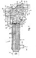
- Fig. 1 and 2 includes an exhaust gas recirculation device 1 only partially shown, hereinafter EGR device 1, a valve assembly 2 and an exhaust gas recirculation cooler 3, hereinafter EGR cooler 3.
- EGR device 1 an exhaust gas recirculation device 1 only partially shown
- the valve assembly 2 is connected directly to the EGR cooler 3, whereby the valve assembly 2 and the EGR cooler 3 form a completely pre-assembled assembly 4, which is easy to handle and facilitates the installation in an exhaust gas recirculation line 5, hereinafter referred to EGR line 5, which is indicated here only by broken lines.
- the EGR device 1 is used in a conventional manner in an internal combustion engine, not shown, which may be arranged in particular in a motor vehicle, to recirculate exhaust gases of the internal combustion engine from an exhaust gas side to a fresh gas side of the internal combustion engine.
- the EGR line 5 is connected on the one hand to the exhaust side and on the other hand to the fresh gas side of the internal combustion engine and contains the valve assembly 2 and the EGR cooler. 3
- the valve assembly 2 comprises a common housing 6, in which two more or less separate gas paths, namely a first gas path 7 and a second gas path 8 are formed, which are indicated here by arrows.
- the valve arrangement 2 also comprises two valves, namely a first valve 9 and a second valve 10, which are each arranged in the housing 6.
- the first valve 9 is assigned to the first gas path 7 and can thus control a gas flow through the first gas path 7.
- the second valve 10 is assigned to the second gas path 8 and can thus control a gas flow through the second gas path 8.
- Both valves 9, 10 are each and independently adjustable between an open position, a closed position and at least one intermediate position.
- the valve arrangement 2 comprises for each valve 9, 10 an actuator, namely a first actuator 11 for actuating the first valve 9 and a second actuator 12 for actuating the second valve 10.
- the common housing 6 contains in addition to the two gas paths 7, 8 also has a coolant path 13, which is also indicated here by arrows.
- the coolant path 13 can be connected to a cooling circuit 14, which is indicated here by arrows drawn with a broken line.
- the housing 6 has an inlet pipe 15 and an outlet pipe 16, which are both connected to the coolant path 13.
- the inlet nozzle 15 is connected via a connecting piece 17 to a coolant outlet 18 of the EGR cooler 3.
- a coolant inlet 19 of the EGR cooler 3 is connected to the cooling circuit 14, so that the coolant of the cooling circuit 14 enters the assembly 4 via the coolant inlet 19 of the EGR cooler 3 and back out of the assembly 4 via the outlet port 16 of the housing 6 exit.
- the housing 6 is preferably made of metal. Preferably, it may be made in one piece.
- the housing 6 is a cast component.
- the cooled housing 6 allows the use of plastic for components of the valve assembly 2 to be mounted on the housing 6. These are, for example, a first drive housing 20 of the first actuator 11 and a second drive housing 21 of the second actuator 12. Both drive housing 20, 21 can be inexpensively made of plastic and can still be attached to the housing 6, although this in the operation of the EGR Device 1 is traversed by hot exhaust gases.
- the housing 6 has an inlet flange 22 with which the housing 6 can be inserted into the EGR device 1.
- the housing 6 is connected via the inlet flange 22 to the EGR line 5.
- the housing 6 also has an outlet flange 23 with which the housing 6 can be inserted into the EGR device 1.
- the housing 6 is connected via the outlet flange 23 directly to the EGR cooler 3.
- a fastener, here a clamp is designated 24.
- the two gas paths 7, 8 now extend within the housing 6 from the inlet flange 22 to the outlet flange 23.
- the housing 6 may be provided with an inlet duct 25 which leads from the inlet flange 22 to inlet sides of the valves 9, 10 which are not designated in greater detail.
- the housing 6 also includes an inlet leg 26.
- This inlet leg 26 is disposed in the inlet duct 25 to form therein two separate inlet channels, namely a first inlet channel 27 and a second inlet channel 28.
- the inlet web 26 is dimensioned so that it extends into the inlet flange 22 and terminates flush therewith.
- the first inlet passage 27 thus connects the inlet flange 22 with the inlet side of the first valve 9, while the second inlet passage 28 connects the inlet flange 22 with the inlet side of the second valve 10.
- the inlet web 26 is preferably an integral part of the housing 6. In the configuration shown here, In which the valve arrangement 2 is arranged upstream of the EGR cooler 3 with regard to the exhaust gas flow, the inlet web 26 can basically be dispensed with.
- the housing 6 has an outlet line 29 which leads from the outlet flange 23 to the outlet sides of the valves 9, 10 which are not designated in any more detail. Furthermore, an outlet web 30 is formed in the housing 6. This is arranged in the outlet line 29 so as to form therein two separate outlet channels, namely a first outlet channel 31 and a second outlet channel 32. Further, the outlet land 30 is dimensioned to project axially beyond the outlet flange 23.
- the first outlet channel 31 connects the outlet side of the first valve 9 with the outlet flange 23.
- the second outlet channel 32 connects the outlet side of the second valve 10 with the outlet flange 23.
- the outlet web 30 is preferably an integral part of the housing 6.
- the EGR cooler 3 includes a cooling space 33 through which liquid coolant can flow, which is connected to the coolant inlet 19 and to the coolant outlet 18 and which is delimited on an exhaust gas inlet side with an inlet wall 34 and on an exhaust gas outlet side with an outlet wall 35.
- the cooling space 33 is penetrated by a plurality of cooling tubes 36, which penetrate on the one hand the inlet wall 34 and on the other hand the outlet wall 35.
- the cooling pipes 36 communicate with an intake space 37 of the EGR cooler 3 at the exhaust gas inlet side and with an exhaust space at the exhaust gas outlet side 38.
- the outlet web 30 of the housing is a cooling space 33 through which liquid coolant can flow, which is connected to the coolant inlet 19 and to the coolant outlet 18 and which is delimited on an exhaust gas inlet side with an inlet wall 34 and on an exhaust gas outlet side with an outlet wall 35.
- the cooling space 33 is penetrated by a plurality of cooling tubes 36, which penetrate on the one hand the inlet wall 34 and on the other hand the outlet wall
- the outlet web 30 can touch the inlet wall 34 or even maintain a comparatively small gap therewith.
- the outlet land 30 in the inlet space 37 separates two inlet part spaces from each other, namely a first inlet part space 39 communicating with the first outlet channel 31 and a second inlet part space 40 communicating with the second outlet channel 32.
- the inlet part spaces 39, 40 communicate independently with each other via the cooling tubes 36 Outlet space 38.
- cooling tubes 36 may be equipped with turbulators and / or fins 41, the flow of heat between exhaust and cooling pipe 36 on the one hand and thus the heat flow during the flow through the respective cooling tube 36 increase between cooling tube 36 and coolant on the other hand.
- valve arrangement 2 is thus used to divide the recirculated exhaust gas flow into two cooling tube groups of different cooling within the EGR cooler 3.
- valve assembly 2 may also be used to divide the recirculated exhaust gas flow between an EGR cooler and an internal or external bypass bypassing the EGR cooler.
- valve assembly 2 is disposed upstream of the EGR cooler 3 with respect to the exhaust gas flow. In another embodiment, it is basically possible to arrange the valve assembly 2 with respect to the exhaust gas flow downstream of the EGR cooler. A cooling of the housing 6 can then be dispensed with.
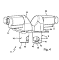
- each valve 9, 10 can, in particular with regard to Fig. 4 , be constructed in the manner of a poppet valve.
- each valve 9, 10 comprises a valve disk 42, which is arranged to be adjustable in the stroke to a valve seat 44 via a valve stem 43.
- the valve seat 44 is formed on a valve sleeve 45, which is also part of the respective valve 9, 10.
- the valve seat 44 together with the valve disk 42 cooperating therewith, forms the inlet side of the respective valve 9, 10.
- the outlet side of the respective valve 9, 10 is formed by a window 46, which is located in the Valve sleeve 45 of the respective valve 9, 10 is recessed.
- the valves 9, 10 thus each comprise all the components required for the functioning of the respective valve 9, 10.
- the valves 9, 10 are designed so that they can be used in the fully assembled state in the housing 6.
- the housing 6 accordingly Fig. 3 a mounting side 47, through which the valves 9, 10 are inserted into the housing 6.
- This mounting side 47 is equipped with a mounting flange 48 and is closed in the assembled state with a flange 49.
- the flange plate 49 is preferably shaped to be complementary to the mounting flange 48.
- a seal 50 arranged to close the mounting side 47 tight.
- the term "axial" in this context refers to the mounting direction, that is, the plug-in direction, with which the valves 9, 10 are inserted into the housing 6.
- Fig. 3 and 4 forms the flange plate 49 together with the attached valves 9, 10 and together with the actuators attached thereto 11, 12 a completely pre-assembled unit 51.
- the assembly of the valve assembly 2 is thereby considerably simplified.
- the flange plate 49 may be made of plastic.
- the flange plate 49 and the drive housings 20, 21 can be made in one piece.
- valves 9, 10 are designed such that they permit not only the two end positions, open position and closed position, but also at least one, preferably any intermediate positions, an exhaust gas recirculation rate, EGR for short, can be achieved with the aid of the valves 9, 10 Set rate, both by the first gas path 7 and by the second gas path 6 independently.
- the valve assembly 2 allows on the one hand the setting of the EGR rate and on the other hand the adjustment of the distribution of recirculated exhaust gases to the two gas paths 7, 8.
- the distribution of the recirculated exhaust gases to the two gas paths 7, 8 ultimately determines the cooling of the recirculated exhaust gases, so that with the aid of the valve assembly 2 in addition to the EGR rate also the exhaust gas cooling is adjustable.
Description
Die vorliegende Erfindung betrifft eine Ventilanordnung für eine Abgasrückführeinrichtung einer Brennkraftmaschine, insbesondere in einem Kraftfahrzeug. Die Erfindung betrifft außerdem eine mit einer derartigen Ventilanordnung ausgestattete Abgasrückführeinrichtung.The present invention relates to a valve arrangement for an exhaust gas recirculation device of an internal combustion engine, in particular in a motor vehicle. The invention also relates to an exhaust gas recirculation device equipped with such a valve arrangement.
Eine Ventilanordnung der eingangs genannten Art ist aus der
Bei der bekannten Ventilanordnung ist in das Gehäuse außerdem ein Abgasrückführkühler eingebaut, wobei das Gehäuse der Ventilanordnung auch Anschlüsse für Vorlauf und Rücklauf des Abgasrückführkühlers aufweist.In the known valve arrangement, an exhaust gas recirculation cooler is also installed in the housing, wherein the housing of the Valve assembly also has connections for flow and return of the exhaust gas recirculation cooler.
Eine weitere Ventilanordnung mit zwei Ventilen zum Steuern von zwei Gaspfaden ist aus der
Bei Brennkraftmaschinen kommt vermehrt eine Abgasrückführung zum Einsatz, um dadurch die Emissionswerte und die Wirtschaftlichkeit der Brennkraftmaschine zu verbessern. Um dabei einen Anstieg von NOx-Emissionen zu vermeiden, ist es erforderlich, die rückgeführten Abgase mit Hilfe eines Abgasrückführkühlers, kurz AGR-Kühler, zu kühlen, da die NOx-Bildung im Verbrennungsprozess mit ansteigender Temperatur überproportional zunimmt.In internal combustion engines, an exhaust gas recirculation is increasingly used, thereby improving the emission values and the economy of the internal combustion engine. In order to avoid an increase in NO x emissions, it is necessary to cool the recirculated exhaust gases using an exhaust gas recirculation cooler, short EGR cooler, since the NO x formation increases disproportionately in the combustion process with increasing temperature.
Dementsprechend besitzt eine moderne Abgasrückführeinrichtung, kurz AGR-Einrichtung, üblicherweise einen AGR-Kühler, der in eine Abgasrückführleitung, kurz AGR-Leitung, eingebaut ist und der an einem mit einem flüssigen Kühlmittel arbeitenden Kühlkreis angeschlossen ist.Accordingly, a modern exhaust gas recirculation (EGR) device typically has an EGR cooler installed in an exhaust gas recirculation line, EGR line for short, which is connected to a cooling circuit operating with a liquid coolant.
Aus der
Dies ist zum Beispiel bei einem Kaltstart der Brennkraftmaschine erwünscht, um dadurch über die Wärme der rückgeführten Abgase die Brennkraftmaschine möglichst rasch aufwärmen zu können. Bei warmer Brennkraftmaschine wird der Bypass deaktiviert, so dass dann die rückgeführten Abgase den AGR-Kühler durchströmen und dabei gekühlt werden.This is desirable, for example, during a cold start of the internal combustion engine, in order thereby to be able to warm up the internal combustion engine as quickly as possible via the heat of the recirculated exhaust gases. When the internal combustion engine is warm, the bypass is deactivated, so that then the recirculated exhaust gases flow through the EGR cooler and thereby cooled.
Aus der
Die vorliegende Erfindung beschäftigt sich mit dem Problem, für eine AGR-Einrichtung einen preiswerten Weg aufzuzeigen, die Menge und die Temperatur der rückgeführten Abgase möglichst genau einzustellen.The present invention addresses the problem of providing an inexpensive way for an EGR device to adjust the amount and temperature of the recirculated exhaust gases as closely as possible.
Erfindungsgemäß wird dieses Problem durch die Gegenstände der unabhängigen Ansprüche gelöst. Vorteilhafte Ausführungsformen sind Gegenstand der abhängigen Ansprüche.According to the invention, this problem is solved by the subject matters of the independent claims. Advantageous embodiments are the subject of the dependent claims.
Die Erfindung beruht auf dem allgemeinen Gedanken, für die AGR-Einrichtung eine Ventilanordnung vorzusehen, die in einem gemeinsamen Gehäuse zwei separate Gaspfade sowie zwei Ventile zur Steuerung dieser Gaspfade enthält, wobei die beiden Ventile jeweils zwischen einer Offenstellung, einer Schließstellung und wenigstens einer Zwischenstellung schaltbar sind. Über die separate Steuerbarkeit der beiden Ventile lässt sich eine beliebige Aufteilung der rückgeführten Abgase auf die beiden Gaspfade erzielen. Beispielsweise kann dadurch ein beliebiges Mischungsverhältnis zwischen einer durch einen Kühler und einer durch einen Bypass geführten Strömung eingestellt werden. Des Weiteren ermöglichen die Zwischenstellungen der beiden Ventile eine Mengenregulierung der rückgeführten Abgase. Folglich lässt sich die Menge der rückgeführten Abgase, die auch als Abgasrückfahrrate oder kurz AGR-Rate bezeichnet wird, einstellen. Hierdurch ist beispielsweise ein zusätzliches Ventil zum Einstellen der AGR-Rate entbehrlich. Die Ventilanordnung kann dadurch vergleichsweise preiswert bauen.The invention is based on the general idea to provide for the EGR device, a valve assembly containing two separate gas paths and two valves for controlling these gas paths in a common housing, wherein the two valves each switchable between an open position, a closed position and at least one intermediate position are. The separate controllability of the two valves can be any division of the recirculated exhaust gases on the two gas paths achieve. For example, this may set any mixing ratio between a flow passed through a radiator and a bypass. Furthermore, the intermediate positions of the two valves allow a volume regulation of the recirculated exhaust gases. Consequently, the amount of the recirculated exhaust gases, which is also referred to as exhaust gas recirculation rate or short EGR rate, can be adjusted. As a result, for example, an additional valve for adjusting the EGR rate is unnecessary. The valve assembly can thereby build comparatively inexpensive.
Zu diesem Zweck wird erfindungsgemäß-vorgeschlagen, das Gehäuse mit einem Einlasssteg auszustatten, der in Einlassleitung angeordnet ist und darin zwei separate Einlasskanäle ausbildet, von denen der erste Einlasskanal mit der Einlassseite des ersten Ventils verbunden ist, während der zweite Einlasskanal mit der Einlassseite des zweiten Ventils verbunden ist, wobei außerdem das Gehäuse mit seinem Einlassflansch an einen Abgasrückführkühler der Abgasrückführeinrichtung anschließbar ist, wobei dann der Einlasssteg im montierten Zustand soweit in einen Auslassraum des Abgasrückführkühlers hineinragt, dass er darin zwei Auslaßteilräume voneinander trennt, die mit Kühlrohren des Abgasrückführkühlers verbunden sind. Zusätzlich oder alternativ schlägt die Erfindung außerdem vor, das Gehäuse mit einem Auslasssteg auszustatten, der in der Auslassleitung angeordnet ist und darin zwei separate Auslaßkanäle ausbildet, von denen der erste Auslasskanal mit der Auslassseite des ersten Ventils verbunden ist, während der zweite Auslasskanal mit der Auslassseite des zweiten Ventils verbunden ist, wobei dann das Gehäuse mit seinem Auslassflansch an einem Abgasrückführkühler der Abgasrückführleitung anschließbar ist, wobei dann der Auslasssteg im montierten Zustand soweit in einen Einlassraum des Abgasnückführkühlers hineinragt, dass er darin zwei Einlassteilräume voneinander trennt, die mit Kühlrohren des Abgasrückführkühlers verbunden sind. Durch die vorgeschlagenen Maßnahmen lassen sich im Abgasrückführkühler zwei separate Abgaspfade realisieren, die über die Ventilanordnung unabhängig voneinander steuerbar sind.For this purpose, the invention proposes to equip the housing with an inlet web, which is arranged in the inlet line and forms therein two separate inlet channels, of which the first inlet channel is connected to the inlet side of the first valve, while the second inlet channel to the inlet side of the second Valve is connected, wherein in addition the housing with its inlet flange to an exhaust gas recirculation cooler of the exhaust gas recirculation device can be connected, in which case the inlet web in mounted state protrudes into an outlet space of the exhaust gas recirculation cooler so far that it separates two outlet part spaces from each other, which are connected to cooling pipes of the exhaust gas recirculation cooler. Additionally or alternatively, the invention also proposes to provide the housing with an outlet land disposed in the outlet conduit forming therein two separate outlet channels, of which the first outlet channel is connected to the outlet side of the first valve, while the second outlet channel is connected to the outlet side the second valve is connected, in which case the housing with its outlet flange to an exhaust gas recirculation cooler of the exhaust gas recirculation line is connected, then the outlet web in the assembled state far protrudes into an inlet space of the exhaust gas recirculation cooler, that it separates two Einlasssteilräume from each other, which is connected to cooling pipes of the exhaust gas recirculation cooler are. The proposed measures make it possible to realize two separate exhaust gas paths in the exhaust gas recirculation cooler, which can be controlled independently of one another via the valve arrangement.
Bei einer vorteilhaften Ausführungsform kann das gemeinsame Gehäuse so ausgestaltet sein, dass es an einen Kühlmittelkreis anschließbar ist. Die Kühlung des Gehäuses ermöglicht die Anordnung der Ventilanordnung stromauf oder einlassseitig des AGR-Kühlers, was vorteilhaft für die genaue Einstellung der AGR-Rate und der Kühlwirkung ist. Des Weiteren ermöglicht das gekühlte Gehäuse die Verwendung von Kunststoff als Werkstoff für Komponenten der Ventilanordnung, die an das Gehäuse angebaut sind. Beispielsweise lassen sich somit Gehäuse von Stellantrieben zur Betätigung der Ventile aus Kunststoff herstellen.In an advantageous embodiment, the common housing can be designed so that it can be connected to a coolant circuit. The cooling of the housing allows the arrangement of the valve assembly upstream or inlet side of the EGR cooler, which is advantageous for the precise adjustment of the EGR rate and the cooling effect. Furthermore, the cooled housing allows the use of plastic as a material for components of the valve assembly which are mounted to the housing. For example, can thus housing of actuators for actuating the valves made of plastic.
Weitere wichtige Merkmale und Vorteile der Erfindung ergeben sich aus den Unteransprüchen, aus den Zeichnungen und aus der zugehörigen Figurenbeschreibung anhand der Zeichnungen.Other important features and advantages of the invention will become apparent from the dependent claims, from the drawings and from the associated figure description with reference to the drawings.
Es versteht sich, dass die vorstehend genannten und die nachstehend noch zu erläuternden Merkmale nicht nur in der jeweils angegebenen Kombination, sondern auch in anderen Kombinationen oder in Alleinstellung verwendbar sind, ohne den Rahmen der vorliegenden Erfindung zu verlassen.It is understood that the features mentioned above and those yet to be explained below can be used not only in the particular combination given, but also in other combinations or in isolation, without departing from the scope of the present invention.
Bevorzugte Ausführungsbeispiele der Erfindung sind in den Zeichnungen dargestellt und werden in der nachfolgenden Beschreibung näher erläutert, wobei sich gleiche Bezugszeichen auf gleiche oder ähnliche oder funktional gleiche Bauteile beziehen.Preferred embodiments of the invention are illustrated in the drawings and will be described in more detail in the following description, wherein like reference numerals refer to the same or similar or functionally identical components.
Es zeigen, jeweils schematisch,
- Fig. 1
- einen Längsschnitt durch eine Ventilanordnung mit daran angebautem Abgasrückführkühler,
- Fig. 2
- einen Längsschnitt wie in
Fig. 1 , jedoch in einer anderen Schnittebene, - Fig. 3
- eine perspektivische Ansicht auf die Ventilanord- nung,
- Fig. 4
- eine Ansicht wie in
Fig. 3 , jedoch bei weggelasse- nem Gehäuse.
- Fig. 1
- a longitudinal section through a valve assembly with attached exhaust gas recirculation cooler,
- Fig. 2
- a longitudinal section as in
Fig. 1 but in another cutting plane, - Fig. 3
- a perspective view of the Ventilanord- tion,
- Fig. 4
- a view like in
Fig. 3 , but with the housing omitted.
Entsprechend den
Entsprechend den
Das gemeinsame Gehäuse 6 enthält neben den beiden Gaspfaden 7, 8 außerdem einen Kühlmittelpfad 13, der hier ebenfalls durch Pfeile angedeutet ist. Der Kühlmittelpfad 13 ist an einen Kühlkreis 14 anschließbar, der hier durch mit unterbrochener Linie gezeichnete Pfeile angedeutet ist. Zum Anschluss an den Kühlkreis 14 weist das Gehäuse 6 einen Einlassstutzen 15 sowie einen Auslassstutzen 16 auf, die beide mit dem Kühlmittelpfad 13 verbunden sind.The
Im gezeigten Beispiel ist der Einlassstutzen 15 über ein Verbindungsstück 17 an einen Kühlmittelauslass 18 des AGR-Kühlers 3 angeschlossen. Ein Kühlmitteleinlass 19 des AGR-Kühlers 3 ist dabei an den Kühlkreis 14 angeschlossen, so dass das Kühlmittel des Kühlkreises 14 über den Kühlmitteleinlass 19 des AGR-Kühlers 3 in die Baugruppe 4 eintritt und über den Auslassstutzen 16 des Gehäuses 6 wieder aus der Baugruppe 4 austritt. Hierdurch wird eine besonders kompakte Bauweise für die Baugruppe 4 erzielt.In the example shown, the
Das Gehäuse 6 ist vorzugsweise aus Metall hergestellt. Vorzugsweise kann es dabei aus einem Stück hergestellt sein. Beispielsweise handelt es sich beim Gehäuse 6 um ein Gussbauteil.The
Durch das gekühlte Gehäuse 6 ist es möglich, die Ventilanordnung 2 bezüglich der Abgasströmung stromauf des AGR-Kühlers 3 anzuordnen. Darüber hinaus ermöglicht das gekühlte Gehäuse 6 die Verwendung von Kunststoff für Komponenten der Ventilanordnung 2, die am Gehäuse 6 anzubauen sind. Hierbei handelt es sich beispielsweise um ein erstes Antriebsgehäuse 20 des ersten Stellantriebs 11 und ein zweites Antriebsgehäuse 21 des zweiten Stellantriebs 12. Beide Antriebsgehäuse 20, 21 können preiswert aus Kunststoff hergestellt werden und können dennoch am Gehäuse 6 befestigt werden, obwohl dieses im Betrieb der AGR-Einrichtung 1 von heißen Abgasen durchströmt wird.Due to the cooled
Entsprechend
Entsprechend
Entsprechend den
Der AGR-Kühler 3 enthält einen vom flüssigen Kühlmittel durchströmbaren Kühlraum 33, der an den Kühlmitteleinlass 19 und an den Kühlmittelauslass 18 angeschlossen ist und der an einer Abgaseinlassseite mit einer Einlasswand 34 und an einer Abgasauslassseite mit einer Auslasswand 35 begrenzt ist. Der Kühlraum 33 ist von mehreren Kühlrohren 36 durchsetzt, die einerseits die Einlasswand 34 und andererseits die Auslasswand 35 durchdringen. Dabei kommunizieren die Kühlrohre 36 an der Abgaseinlassseite mit einem Einlassraum 37 des AGR-Kühlers 3 und an der Abgasauslassseite mit einem Auslassraum 38. Der Auslasssteg 30 des Gehäuses. 6 ist zweckmäßig so dimensioniert, dass er im montierten Zustand der Baugruppe 4 so weit in den Einlassraum 37 hineinragt, dass er sich bis zur Einlasswand 34 erstreckt. Dabei kann der Auslasssteg 30 die Einlasswand 34 berühren oder auch einen vergleichsweise kleinen Spalt zu dieser einhalten. Jedenfalls trennt der Auslasssteg 30 im Einlassraum 37 zwei Einlassteilräume voneinander ab, nämlich einen mit dem ersten Auslasskanal 31 kommunizierenden ersten Einlassteilraum 39 und einen mit dem zweiten Auslasskanal 32 kommunizierenden zweiten Einlassteilraum 40. Die Einlassteilräume 39, 40 kommunizieren unabhängig voneinander über die Kühlrohre 36 mit dem Auslassraum 38. Hierdurch ist es möglich, durch entsprechende Betätigungen der Ventile 9, 10 die Abgasströmung ausschließlich durch die Kühlrohre 36 des ersten Einlassteilraums 39 oder ausschließlich durch die Kühlrohre 36 des zweiten Einlassteilraums 40 oder in einem beliebigen Aufteilungsverhältnis durch die Kühlrohre 36 der beiden Einlassteilräume 39, 40 zu führen. Besonders interessant ist eine derartige Ausführungsform dann, wenn durch eine entsprechende Ausgestaltung des AGR-Kühlers 3 die Durchströmung der Kühlrohre 36, die von dem einen Einlassteilraum 39 abgehen, zu einer anderen Kühlwirkung für die Abgase führt als die Durchströmung der Kühlrohre 36, die vom anderen Einlassteilraum 40 abgehen. Beispielsweise können die hier dem ersten Einlassteilraum 39 zugeordneten Kühlrohre 36 mit Turbulatoren und/oder Lamellen 41 ausgestattet sein, die bei der Durchströmung des jeweiligen Kühlrohrs 36 den Wärmestrom zwischen Abgas und Kühlrohr 36 einerseits und somit den Wärmestrom zwischen Kühlrohr 36 und Kühlmittel andererseits erhöhen.The
Bei der hier gezeigten, bevorzugten Ausführungsform wird die Ventilanordnung 2 somit dazu verwendet, die rückgeführte Abgasströmung auf zwei unterschiedlich stark kühlende Kühlrohrgruppen innerhalb des AGR-Kühlers 3 aufzuteilen. Bei einer anderen Ausführungsform kann die Ventilanordnung 2 auch dazu genutzt werden, die rückgeführte Abgasströmung zwischen einem AGR-Kühler und einem den AGR-Kühler umgehenden, internen oder externen Bypass aufzuteilen.In the preferred embodiment shown here, the
Bei der gezeigten Ausführungsform ist die Ventilanordnung 2 bezüglich der Abgasströmung stromauf des AGR-Kühlers 3 angeordnet. Bei einer anderen Ausführungsform ist es grundsätzlich möglich, den Ventilanordnung 2 bezüglich der Abgasströmung stromab des AGR-Kühlers anzuordnen. Eine Kühlung des Gehäuses 6 kann dann entbehrlich sein.In the illustrated embodiment, the
Die Ventile 9, 10 können, insbesondere im Hinblick auf
Entsprechend den
Da bei der erfindungsgemäßen Ventilanordnung 2 beide Ventile 9, 10 so ausgestaltet sind, dass sie neben den beiden Endstellungen, Offenstellung und Schließstellung, zumindest eine, vorzugsweise jedoch beliebig viele Zwischenstellungen ermöglichen, lassen sich mit Hilfe der Ventile 9, 10 eine Abgasrückführrate, kurz AGR-Rate, sowohl durch den ersten Gaspfad 7 als auch durch den zweiten Gaspfad 6 unabhängig voneinander einstellen. Somit ermöglicht die Ventilanordnung 2 einerseits die Einstellung der AGR-Rate und andererseits die Einstellung der Verteilung der rückgeführten Abgase auf die beiden Gaspfade 7, 8. Die Verteilung der rückgeführten Abgase auf die beiden Gaspfade 7, 8 bestimmt letztlich die Kühlung der rückgeführten Abgase, so dass mit Hilfe der Ventilanordnung 2 neben der AGR-Rate außerdem die Abgaskühlung einstellbar ist.Since in the case of the
Claims (13)
- A valve arrangement for an exhaust gas recirculation device (1) of an internal combustion engine, especially in a motor vehicle,- comprising, for controlling a first gas path (7), a first valve (9), which is mobile between an open position, a closed position, and at least one intermediate position,- comprising, for controlling a second gas path (8) separated from the first gas path (7), a second valve (10), which is mobile independently from the first valve (9) between an open position, a closed position, and at least one intermediate position,- comprising a common housing (6), in which both valves (9, 10) are arranged, and through which the two gas paths (7, 8) are guided,- wherein the housing (6) comprises an inlet flange (22) and an outlet flange (23) by means of which the housing (6) can be integrated in the exhaust gas recirculation device (1), and between which the two gas paths (7, 8) extend,characterized in- that the housing (6) comprises an inlet partition (26) which is arranged in the inlet line (25) and which forms two separate inlet channels (27, 28) therein, whereby the first inlet channel (27) is connected with the inlet side of the first valve (9), while the second inlet channel (28) is connected with the inlet side of the second valve (10), wherein the housing (6) can be connected with its outlet flange (23) to an exhaust gas recirculation cooler (3) of the exhaust gas recirculation device (1), wherein the outlet partition (30), in the mounted state, projects so far into an inlet chamber (37) of the exhaust gas recirculation cooler (3), that it separates therein two inlet sub-chambers (39, 40) from each other, which are connected with cooling tubes (36) of the exhaust gas recirculation cooler (3), and/or- that the housing (6) comprises an outlet partition (30), which is arranged in the outlet line (29) and forms two separate outlet channels (31, 32) therein, whereby the first outlet channel (31) is connected with the outlet side of the first valve (9), while the second outlet channel (32) is connected with the outlet side of the second valve (10), wherein the housing (6) can be connected with its inlet flange (22) to an exhaust gas recirculation cooler (3) of the exhaust gas recirculation device (1), wherein the inlet partition (26), in the mounted state, projects so far into an outlet chamber (38) of the exhaust gas recirculation cooler (3) that it separates therein two outlet sub-chambers, which are connected with cooling tubes (36) of the exhaust gas recirculation cooler (3).
- The valve arrangement according to claim 1,
characterized in- that the housing (6) includes a coolant path (13) and- that the housing (6) comprises an inlet port (15) connected with the coolant path (13) and an outlet port (16) connected with the coolant path (13). - The valve arrangement according to claim 1 or claim 2,
characterized in- that the housing (6) is made of metal. - The valve arrangement according to one of the claims 1 to 3,
characterized in- that the housing (6) is made of one piece. - The valve arrangement according to one of the claims 1 to 4,
characterized in- that for actuating the first valve (9), a first actuator drive (11) is provided, which is attached with its first drive housing (20) at the common housing (6), and- that for actuating the second valve (10), a second actuator drive (12) is provided, which is attached with its second drive housing (21) at the common housing (6). - The valve arrangement according to claim 5,
characterized in
that the first drive housing (20) and the second drive housing (21) are made of plastic. - The valve arrangement according to anyone of the claims 1 to 6,
characterized in- that the housing (6) comprises an inlet line (25) which extends from the inlet flange (22) to the inlet sides of the valves (9, 10). - The valve arrangement according to anyone of the claims 1 to 7,
characterized in- that the inlet partition (26) extends up to, or into the inlet flange (22), or projects axially beyond it. - The valve arrangement according to anyone of the claims 1 to 8,
characterized in- that the housing (6) comprises an outlet line (29), which extends from the outlet flange (23) to the outlet sides of the valves (9, 10). - The valve arrangement according to anyone of the claims 1 to 9,
characterized in- that the outlet partition (30) extends up to, or into the outlet flange (23), or projects axially beyond it. - The valve arrangement according to any one of the claims 1 to 10,
characterized in- that the housing (6) comprises a mounting side (47), through which the valves (9, 10) can be inserted into the housing, whereby the mounting side has a mounting flange (48) and can be closed with a flange plate (49). - The valve arrangement according to anyone of the claims 1 to 11,
characterized in- that the flange plate (49) with the valves (9, 10) attached thereto, and the actuator drives (11, 12) attached thereto for actuating of the valves (9, 10), form a unit (51) which can be preassembled. - The exhaust gas recirculation device of an internal combustion engine, especially in a motor vehicle, comprising a valve arrangement (2) according to any one of the claims 1 to 12, the housing (6) of which is connected directly to an exhaust gas recirculation cooler (3) via the inlet flange (22) or the outlet flange (23).
Applications Claiming Priority (2)
| Application Number | Priority Date | Filing Date | Title |
|---|---|---|---|
| DE102006023852A DE102006023852A1 (en) | 2006-05-19 | 2006-05-19 | Valve arrangement for an exhaust gas recirculation device |
| PCT/EP2007/054460 WO2007134962A1 (en) | 2006-05-19 | 2007-05-09 | Valve arrangement for an exhaust gas recirculation device |
Publications (2)
| Publication Number | Publication Date |
|---|---|
| EP2018472A1 EP2018472A1 (en) | 2009-01-28 |
| EP2018472B1 true EP2018472B1 (en) | 2010-08-18 |
Family
ID=38191792
Family Applications (1)
| Application Number | Title | Priority Date | Filing Date |
|---|---|---|---|
| EP07728912A Expired - Fee Related EP2018472B1 (en) | 2006-05-19 | 2007-05-09 | Valve arrangement for an exhaust gas recirculation device |
Country Status (6)
| Country | Link |
|---|---|
| US (1) | US8225773B2 (en) |
| EP (1) | EP2018472B1 (en) |
| CN (1) | CN101495743A (en) |
| BR (1) | BRPI0712024A2 (en) |
| DE (2) | DE102006023852A1 (en) |
| WO (1) | WO2007134962A1 (en) |
Families Citing this family (20)
| Publication number | Priority date | Publication date | Assignee | Title |
|---|---|---|---|---|
| US20090260605A1 (en) * | 2007-11-01 | 2009-10-22 | Cummins Intellectual Properties, Inc. | Staged arrangement of egr coolers to optimize performance |
| JP5380522B2 (en) * | 2008-03-31 | 2014-01-08 | ボーグワーナー インコーポレーテッド | Multiport valve |
| DE102008051268A1 (en) * | 2008-10-10 | 2010-04-15 | Mahle International Gmbh | cooling device |
| DE102010014843B4 (en) | 2010-04-13 | 2020-06-25 | Pierburg Gmbh | Exhaust gas cooling module for an internal combustion engine |
| DE102010014842B3 (en) * | 2010-04-13 | 2011-09-22 | Pierburg Gmbh | Exhaust gas cooling module for an internal combustion engine |
| GB2481024B (en) * | 2010-06-08 | 2015-12-16 | Gm Global Tech Operations Inc | Exhaust gas recirculation (EGR) valve assembly for an internal combustion engine |
| JP5387612B2 (en) * | 2010-06-25 | 2014-01-15 | マツダ株式会社 | Engine exhaust gas recirculation system |
| KR101016191B1 (en) * | 2010-07-08 | 2011-02-24 | 주식회사 유니크 | Bypass valve for vehicle |
| FR2966884B1 (en) * | 2010-10-29 | 2012-11-09 | Renault Sa | PROTECTIVE DEVICE FOR AN EXHAUST GAS RECIRCULATION COMPONENT |
| JP5799963B2 (en) * | 2011-02-08 | 2015-10-28 | トヨタ自動車株式会社 | Exhaust circulation device for internal combustion engine |
| FR2983532B1 (en) * | 2011-12-01 | 2015-02-13 | Valeo Sys Controle Moteur Sas | VALVE FOR A GAS CIRCUIT CIRCUIT IN A VEHICLE |
| DE102012004009A1 (en) | 2012-02-25 | 2012-09-13 | Daimler Ag | Exhaust manifold for exhaust system of internal combustion engine mounted in motor vehicle, has adjustable controller which is mounted in control housing separately from distributor housing, and stop contours are formed on control housing |
| DE102012103374B4 (en) * | 2012-04-18 | 2015-01-08 | Pierburg Gmbh | Exhaust flap device for an internal combustion engine |
| WO2013169253A1 (en) * | 2012-05-10 | 2013-11-14 | International Engine Intellectual Property Company, Llc | Modulating bypass valve |
| US20140311466A1 (en) * | 2013-04-17 | 2014-10-23 | Caterpillar Inc. | Coolant Inlet Structures for Heat Exchangers for Exhaust Gas Recirculation Systems |
| DE112014001893T5 (en) * | 2013-05-10 | 2016-01-07 | Modine Manufacturing Company | Exhaust gas heat exchanger and method |
| KR101480633B1 (en) * | 2013-08-30 | 2015-01-08 | 현대자동차주식회사 | EGR Cooler and EGR Cooler Device |
| JP5920381B2 (en) * | 2014-02-27 | 2016-05-18 | 株式会社デンソー | Intake and exhaust system for internal combustion engine |
| US20160169166A1 (en) * | 2014-12-10 | 2016-06-16 | Hyundai Motor Company | Structure of engine system |
| CN106401809B (en) * | 2015-07-31 | 2020-11-03 | 无锡法雷奥汽车零配件系统有限公司 | Valve for an internal combustion engine of a motor vehicle and valve assembly comprising such a valve |
Family Cites Families (19)
| Publication number | Priority date | Publication date | Assignee | Title |
|---|---|---|---|---|
| US4020809A (en) * | 1975-06-02 | 1977-05-03 | Caterpillar Tractor Co. | Exhaust gas recirculation system for a diesel engine |
| US4267812A (en) | 1979-10-09 | 1981-05-19 | Ford Motor Company | Engine EGR cooler |
| US5617726A (en) | 1995-03-31 | 1997-04-08 | Cummins Engine Company, Inc. | Cooled exhaust gas recirculation system with load and ambient bypasses |
| US5732688A (en) * | 1996-12-11 | 1998-03-31 | Cummins Engine Company, Inc. | System for controlling recirculated exhaust gas temperature in an internal combustion engine |
| DE19831140B4 (en) * | 1998-07-11 | 2009-08-20 | Pierburg Gmbh | Exhaust gas recirculation valve |
| US6014960A (en) * | 1998-11-09 | 2000-01-18 | Navistar International Transportation Corp | Exhaust gas recirculation control apparatus |
| AU2264301A (en) * | 1999-12-14 | 2001-06-25 | Cooperstandard Automotive Fluid Systems | Integrated egr valve and cooler |
| DE19962863B4 (en) | 1999-12-24 | 2013-09-19 | Behr Gmbh & Co. Kg | Heat exchanger |
| EP1275838A1 (en) * | 2001-07-11 | 2003-01-15 | Cooper-Standard Automotive (Deutschland) GmbH | Exhaust recirculation system |
| US6584767B1 (en) * | 2001-11-09 | 2003-07-01 | Steve Koenig | Exhaust diverter |
| JP2003254169A (en) * | 2002-03-05 | 2003-09-10 | Hino Motors Ltd | Egr valve |
| DE102004010117A1 (en) * | 2003-02-27 | 2004-11-18 | Denso Corp., Kariya | Exhaust gas recirculation circuit for motor vehicle internal combustion engine has regulating valve connected to heat exchanger outlet and bypass pipe |
| DE10344217B4 (en) | 2003-09-22 | 2014-05-28 | Mahle Filtersysteme Gmbh | Fresh gas leading section of a fresh gas system |
| DE10344218B4 (en) | 2003-09-22 | 2014-10-23 | Mahle Filtersysteme Gmbh | Exhaust gas recirculation valve |
| EP1685322A1 (en) * | 2003-10-17 | 2006-08-02 | Honeywell International, Inc. | Internal bypass exhaust gas cooler |
| US7121088B2 (en) * | 2004-05-24 | 2006-10-17 | General Motors Corporation | Automotive exhaust valve |
| US7814748B2 (en) * | 2006-05-05 | 2010-10-19 | Continental Automotive Canada, Inc. | Exhaust bypass valve remote linkage |
| US7900609B2 (en) * | 2007-04-18 | 2011-03-08 | Continental Automotive Canada, Inc. | Dual exhaust gas recirculation valve |
| US7987837B2 (en) * | 2010-02-16 | 2011-08-02 | Ford Global Technologies, Llc | Exhaust treatment system for internal combustion engine |
-
2006
- 2006-05-19 DE DE102006023852A patent/DE102006023852A1/en not_active Withdrawn
-
2007
- 2007-05-09 BR BRPI0712024-9A patent/BRPI0712024A2/en not_active IP Right Cessation
- 2007-05-09 EP EP07728912A patent/EP2018472B1/en not_active Expired - Fee Related
- 2007-05-09 WO PCT/EP2007/054460 patent/WO2007134962A1/en active Application Filing
- 2007-05-09 US US12/301,368 patent/US8225773B2/en active Active
- 2007-05-09 CN CNA2007800181170A patent/CN101495743A/en active Pending
- 2007-05-09 DE DE502007004793T patent/DE502007004793D1/en active Active
Also Published As
| Publication number | Publication date |
|---|---|
| BRPI0712024A2 (en) | 2011-12-27 |
| DE102006023852A1 (en) | 2007-11-22 |
| EP2018472A1 (en) | 2009-01-28 |
| US8225773B2 (en) | 2012-07-24 |
| WO2007134962A1 (en) | 2007-11-29 |
| CN101495743A (en) | 2009-07-29 |
| US20100108041A1 (en) | 2010-05-06 |
| DE502007004793D1 (en) | 2010-09-30 |
Similar Documents
| Publication | Publication Date | Title |
|---|---|---|
| EP2018472B1 (en) | Valve arrangement for an exhaust gas recirculation device | |
| EP1589214B1 (en) | Exhaust recirculation system | |
| EP2021612B1 (en) | Exhaust gas recirculation device | |
| EP0987427B1 (en) | Device for recirculating an exhaust gas stream to the intake conduit of an engine | |
| EP1747369B1 (en) | Controllable two-way valve | |
| EP1870591B1 (en) | Intake device for an internal combustion engine | |
| EP2211048B1 (en) | Exhaust gas flap device and exhaust gas heat recovery system of a combustion engine | |
| EP1857761B1 (en) | Heat exchange device for combustion engines | |
| EP2336538B1 (en) | Device for recirculation of exhaust gas and method for heating a coolant of a combustion engine and use of the exhaust gas recirculation device | |
| EP2175221A2 (en) | Cooling device | |
| DE10344218B4 (en) | Exhaust gas recirculation valve | |
| EP1707790B1 (en) | Exhaust gas recirculation system | |
| EP2558703A1 (en) | Exhaust-gas cooling module for an internal combustion engine | |
| DE102016200510A1 (en) | Device and method for exhaust gas recirculation | |
| DE102005039794B4 (en) | Exhaust gas heat exchanger | |
| EP1703115B1 (en) | Thermostatic valve with integrated exhaust gas recirculation valve | |
| DE10350521A1 (en) | Device for recirculating exhaust gases back into an internal combustion engine comprises an exhaust gas recirculation line that branches into two branch lines, and a cooling device arranged on one of the branch lines | |
| EP1598543B1 (en) | Adjustable two-way valve device | |
| DE102008060224B4 (en) | Oil exhaust cooling module for an internal combustion engine | |
| DE10344217A1 (en) | Fresh gas-guiding section of a fresh gas system for an internal combustion engine, especially in a motor vehicle, comprises a lateral inlet opening for recirculated exhaust gas from an exhaust gas recirculation unit of the engine | |
| DE102019116156A1 (en) | Valve, exhaust system for an internal combustion engine and vehicle with an internal combustion engine | |
| EP2466103A2 (en) | Waste gas reclaim module for a combustion engine | |
| DE102009036284A1 (en) | Valve device for internal combustion engine, has channel, which is subdivided into two channels, two passages and two stroke valves which control passages and are connected firmly with moving transmission element | |
| WO2021139886A1 (en) | Exhaust gas system of an internal combustion engine | |
| DE10362332B4 (en) | Exhaust gas recirculation valve |
Legal Events
| Date | Code | Title | Description |
|---|---|---|---|
| PUAI | Public reference made under article 153(3) epc to a published international application that has entered the european phase |
Free format text: ORIGINAL CODE: 0009012 |
|
| 17P | Request for examination filed |
Effective date: 20081105 |
|
| AK | Designated contracting states |
Kind code of ref document: A1 Designated state(s): AT BE BG CH CY CZ DE DK EE ES FI FR GB GR HU IE IS IT LI LT LU LV MC MT NL PL PT RO SE SI SK TR |
|
| AX | Request for extension of the european patent |
Extension state: AL BA HR MK RS |
|
| RIN1 | Information on inventor provided before grant (corrected) |
Inventor name: GRUENER, ANDREAS Inventor name: SENDOR, ROBERT Inventor name: SCHWALK, BERNHARD Inventor name: KNAUSS, RUEDIGER |
|
| RBV | Designated contracting states (corrected) |
Designated state(s): DE FR GB |
|
| 17Q | First examination report despatched |
Effective date: 20090608 |
|
| GRAP | Despatch of communication of intention to grant a patent |
Free format text: ORIGINAL CODE: EPIDOSNIGR1 |
|
| GRAS | Grant fee paid |
Free format text: ORIGINAL CODE: EPIDOSNIGR3 |
|
| GRAA | (expected) grant |
Free format text: ORIGINAL CODE: 0009210 |
|
| AK | Designated contracting states |
Kind code of ref document: B1 Designated state(s): DE FR GB |
|
| REG | Reference to a national code |
Ref country code: GB Ref legal event code: FG4D Free format text: NOT ENGLISH |
|
| REF | Corresponds to: |
Ref document number: 502007004793 Country of ref document: DE Date of ref document: 20100930 Kind code of ref document: P |
|
| PLBE | No opposition filed within time limit |
Free format text: ORIGINAL CODE: 0009261 |
|
| STAA | Information on the status of an ep patent application or granted ep patent |
Free format text: STATUS: NO OPPOSITION FILED WITHIN TIME LIMIT |
|
| 26N | No opposition filed |
Effective date: 20110519 |
|
| REG | Reference to a national code |
Ref country code: DE Ref legal event code: R097 Ref document number: 502007004793 Country of ref document: DE Effective date: 20110519 |
|
| REG | Reference to a national code |
Ref country code: FR Ref legal event code: PLFP Year of fee payment: 10 |
|
| REG | Reference to a national code |
Ref country code: DE Ref legal event code: R084 Ref document number: 502007004793 Country of ref document: DE |
|
| REG | Reference to a national code |
Ref country code: FR Ref legal event code: PLFP Year of fee payment: 11 |
|
| REG | Reference to a national code |
Ref country code: FR Ref legal event code: PLFP Year of fee payment: 12 |
|
| PGFP | Annual fee paid to national office [announced via postgrant information from national office to epo] |
Ref country code: RO Payment date: 20180827 Year of fee payment: 14 |
|
| PGFP | Annual fee paid to national office [announced via postgrant information from national office to epo] |
Ref country code: FR Payment date: 20190528 Year of fee payment: 13 |
|
| PGFP | Annual fee paid to national office [announced via postgrant information from national office to epo] |
Ref country code: GB Payment date: 20190529 Year of fee payment: 13 |
|
| REG | Reference to a national code |
Ref country code: DE Ref legal event code: R119 Ref document number: 502007004793 Country of ref document: DE |
|
| PG25 | Lapsed in a contracting state [announced via postgrant information from national office to epo] |
Ref country code: DE Free format text: LAPSE BECAUSE OF NON-PAYMENT OF DUE FEES Effective date: 20191203 |
|
| GBPC | Gb: european patent ceased through non-payment of renewal fee |
Effective date: 20200509 |
|
| PG25 | Lapsed in a contracting state [announced via postgrant information from national office to epo] |
Ref country code: GB Free format text: LAPSE BECAUSE OF NON-PAYMENT OF DUE FEES Effective date: 20200509 Ref country code: FR Free format text: LAPSE BECAUSE OF NON-PAYMENT OF DUE FEES Effective date: 20200531 |