EP2018447B1 - Apparatus and method for processing of plant material - Google Patents
Apparatus and method for processing of plant material Download PDFInfo
- Publication number
- EP2018447B1 EP2018447B1 EP06704990.8A EP06704990A EP2018447B1 EP 2018447 B1 EP2018447 B1 EP 2018447B1 EP 06704990 A EP06704990 A EP 06704990A EP 2018447 B1 EP2018447 B1 EP 2018447B1
- Authority
- EP
- European Patent Office
- Prior art keywords
- stalks
- roller
- bending element
- teeth
- toothed roller
- Prior art date
- Legal status (The legal status is an assumption and is not a legal conclusion. Google has not performed a legal analysis and makes no representation as to the accuracy of the status listed.)
- Not-in-force
Links
Images


Classifications
-
- D—TEXTILES; PAPER
- D01—NATURAL OR MAN-MADE THREADS OR FIBRES; SPINNING
- D01B—MECHANICAL TREATMENT OF NATURAL FIBROUS OR FILAMENTARY MATERIAL TO OBTAIN FIBRES OF FILAMENTS, e.g. FOR SPINNING
- D01B1/00—Mechanical separation of fibres from plant material, e.g. seeds, leaves, stalks
- D01B1/10—Separating vegetable fibres from stalks or leaves
- D01B1/14—Breaking or scutching, e.g. of flax; Decorticating
- D01B1/22—Breaking or scutching, e.g. of flax; Decorticating with crushing or breaking rollers or plates
-
- D—TEXTILES; PAPER
- D01—NATURAL OR MAN-MADE THREADS OR FIBRES; SPINNING
- D01B—MECHANICAL TREATMENT OF NATURAL FIBROUS OR FILAMENTARY MATERIAL TO OBTAIN FIBRES OF FILAMENTS, e.g. FOR SPINNING
- D01B1/00—Mechanical separation of fibres from plant material, e.g. seeds, leaves, stalks
- D01B1/10—Separating vegetable fibres from stalks or leaves
- D01B1/14—Breaking or scutching, e.g. of flax; Decorticating
- D01B1/24—Breaking or scutching, e.g. of flax; Decorticating with toothed or other pointed devices
Definitions
- the present invention relates to improvements in or relating to the processing of bast crops or any crop containing an inner core surrounded by an outer fibrous layer.
- crops include, but are not limited to, Cannabis sativa, better known as hemp, Kenaf, Ramie, sugar cane, nettles, Jute, Sesbania or Sisal.
- Bast crops are defined as a plant that contains a fibrous layer of bast fibres usually surrounding a pith or woody core. Some bast crops have the fibrous layers contained in bundles within the leaf of the plant. In particular, hemp contains a fibrous bast layer within the skin of the stem and branches, surrounding a woody core (herein known as hurd).
- Hemp has a number of commercial uses due to the properties of its bast and hurd fibre, which include strength, resilience and insulation.
- the bast fibre which can be extracted from the outer fibrous layer of a hemp stalk, has a variety of uses and may be a constituent in the production of paper, composites, fibreboard, insulation and non-woven products. Hemp fibre also has the capacity to replace cotton, wool and synthetics as a component for textiles. With the gradual relaxation of strict legislative controls over cultivation and processing, hemp will become increasingly attractive to industry as a competitive alternative to current fibre sources.
- the stalk of a hemp plant is generally circular in cross-section, having a fibrous outer layer (skin) and an inner core (hurd).
- the bast fibre of the plant is located within the skin and generally, is the more valuable commodity. Hurd has applications in paper, construction and animal bedding. It is therefore desirable to separate the bast fibre from the hurd so as to maximise the options for value-adding.
- Specification GB 2205865 treats plant stalks as soon as they are cut, however the hurd is removed from the stalk by crushing the stalks between cylinders.
- Specifications GB 693833 and US 5465464 describe methods of processing which, while not requiring time consuming pre-treatment of the raw material, are not directed towards the processing of green or freshly cut plant stalks, particularly, green hemp stalks.
- None of such prior art methods are suited to broadacre production involving both the harvesting of the hemp crop and efficiently separating the bast fibre from the hurd of the harvested stalk on a commercial scale.
- Patent specification WO 97/45573 describes a method and apparatus for processing the green plant stalk of a bast crop.
- the bonds between the fibre and the hurd are ruptured.
- the stalk is subsequently split and the exposed hurd is stripped from the fibre by the abrasion of a toothed roller on the hurd.
- Bond rupturing is affected by passing the green stalks between a complex series of counter-rotating pressing rollers, before the stalk is split and stripped of the hurd.
- This proposal is somewhat complex and requires significant power to drive the rollers.
- US2293056 discloses an apparatus for abstracting and treating fibers from fiber-bearing plants comprising a rotor member and an oscillating head having an upper bar, said members being provided with edged instruments adapted to co-operate in non-intersecting paths upon opposite faces of fibrous material.
- FR519207 discloses a grinding machine composed of two sets of devices, each set consisting of two wheels fitted with teeth, an endless chain, a mill and two drum pallets.
- WO2004/088006 discloses an apparatus for processing stalk having a fibrous outer part and an inner hurd comprising: a feeder for feeding the stalks for processing; a decorticator for decorticating the fed stalks comprising: a bending element to which the stalks are fed at a predetermined speed; a striking means that cause each stalk to bend over the bending element and to thereby fracture the hurd across the stalk and/or longitudinally split the skin at various locations along the stalk length, wherein the striking means further serves to separate the hurd from the fibrous outer part of the stalk.
- he present invention provides an effective alternative to the foregoing proposals for the processing of a bast crop, and in particular, green or non-retted bast crops. It is also specifically made so that the one system is both gentle enough to process green fresh hemp full of fluid in the field and also hard and strong enough to process hard dry hemp wherein the hurd and the gums are dry and intractable either as dry unretted hemp or dry retted hemp standing in fields or presented to the system as dry bales.
- the invention is capable of processing retted stems, but in a preferred embodiment, enables processing of hemp and bast crops without any need for costly, destructive, damaging, expensive and time consuming retting.
- the present invention provides an apparatus for processing green or un-retted plant stalks having a fibrous outer part and an inner section, the apparatus comprising: a toothed rotatable roller and a bending element, wherein the toothed roller includes teeth projecting from the surface of the roller; each of the teeth comprising a leading portion and a trailing portion relative to the direction of roller rotation wherein the leading portion extends a shorter radial distance from the surface of the roller compared to the trailing portion, characterised in that the bending element is positioned between 13 to 23mm below a scissor plane passing through a mid point of the leading portion of a tooth when the tooth is horizontally aligned on the toothed roller, such that on contact of the stalks with the bending element and the teeth, the stalks are caused to bend and the fibrous outer part is caused to split and the inner section, is substantially separated from the fibrous outer part.
- the toothed roller is in the form of a cylinder or a disc (i.e., a narrow cylinder), with teeth projecting from its circumferential periphery. It will be appreciated that the longer the cylinder, the more stalks are capable of being processed simultaneously.
- the teeth may extend across the entire roller length or may be extend across only a portion of the roller length. Preferably the teeth extend across the substantial roller length.
- the teeth may be fabricated in two or more discrete parts, or they may each be monolithic. When fabricated in two or more discrete parts, the parts may be fastened together by any means known to persons skilled in the art such as, for example, welding and/or bolting.
- the toothed roller may be an integral unit and in this case, may be fabricated from a single metal piece.
- the teeth are preferably recessed within the circumference of the roller as opposed to being fastened at the point flush with the circumferential plane of the roller.
- the teeth located on the toothed roller may be of any configuration provided each tooth is able to achieve both splitting of the outer skin and scooping of the inner hurd per revolution of the cylinder.
- the profile of each tooth between the leading portion and trailing portion is be stepped, a continuous curve or any configuration that allows each tooth to achieve splitting of the stalk outer skin followed by scooping of the inner hurd.
- the teeth dimensions are within the range of about 1.0 to 1.5, more preferably about 1.2.
- the bending element is in the form of a hump of which the side that faces the toothed roller follows the curvature of the toothed roller.
- the gap between the bending element and the toothed roller is adjustable.
- the gap is adjusted at about 0.5 mm to about 6 mm, preferably about 3 mm.
- the stalks are automatically fed to the bending element by automated means.
- automated means of feeding the stalks to the bending element may be achieved with a feeder means in the form of a pair of rollers through which the stalk(s) is/are drawn.
- the toothed roller rotates at a speed of about 1600 rpm, while the feeder rollers rotate between about 100 to about 200 rpm.
- the speed of the feeder rollers is maintained at about 360 rpm while the speed of the toothed roller is maintained at about 2500 rpm.
- the present invention also provides a method of processing one or more plant stalks having a fibrous outer part (skin) and an inner section (hurd), the method comprising feeding the plant stalk(s) to the apparatus of the present invention.
- the stalks are in a green or in an un-retted state.
- the method further comprises (a) cutting the one or more stalks in a green or in an un-retted state and optionally removing any leaves, (b) optionally squeezing the one or more stalks to remove at least a partial amount of gum within the stalks, (c) separating the hurd from the skin by feeding the one or more stalks to an apparatus as described herein, (d) optionally squeezing the one or more stalks to remove at least a partial amount of gum within the stalks, and (e) drying the separated skin.
- steps (d) and optionally step (e) are performed substantially immediately after the separation of the hurd and skin fractions in step (c).
- the one or more stalks are cut or harvested using a suitable cutting head and the apparatus according to the present invention mounted on a forage or combine harvester.
- the toothed roller may be fabricated from a range of materials, for example, from high density polymers or from metals such as hardened steel. As the one or more plant stalks are fed to the apparatus, the teeth located on the toothed roller each successively contact one or more plant stalks. It will be appreciated that high impact forces may be generated upon contact of each of the teeth with a plant stalk. The use of stronger materials to fabricate the toothed roller allows higher impact forces to be withstood by the toothed roller which are generated through contact of the plant stalk(s) with the teeth.
- the toothed roller may be in the form of a cylinder or a disc (i.e., a narrow cylinder), with teeth projecting from its circumferential periphery. It will be appreciated that the longer the cylinder, the more stalks are capable of being processed simultaneously.
- the teeth may extend across the entire roller length or may be extend across only a portion of the roller length. Preferably the teeth extend across the substantial roller length.
- the teeth may be fabricated in two or more discrete parts, or they may each be monolithic. When fabricated in two or more discrete parts, the parts may be fastened together by any means known to persons skilled in the art such as, for example, welding and/or bolting.
- the toothed roller may be an integral unit.
- the toothed roller may be fabricated from a single metal piece wherein the teeth are cut out by the use of a lathe.
- the connection points between the cylinder and the teeth will be weakened stress points which are subject to failure upon contact of the teeth with the one or more plant stalks.
- the teeth may be recessed within the circumference of the roller as opposed to being fastened at the point flush with the circumferential plane of the roller. In this way, part, or most of the impact force is transferred to the cylindrical section of the roller, as opposed to being handled by the teeth alone. This allows greater impact forces to be withstood by the apparatus upon sequential contact of the one or more plant stalks with the teeth as the roller revolves.
- the teeth located on the toothed roller may comprise any configuration provided each tooth is able to achieve both splitting of the outer skin and scooping of the inner hurd per revolution of the cylinder.
- the profile of each tooth between the leading portion and trailing portion may be stepped, a continuous curve or any configuration that allows each tooth to achieve splitting of the stalk outer skin followed by scooping of the inner hurd.
- the teeth dimensions are preferably within the range of 1.0 to 1.5, more preferably 1.2.
- teeth edges that are sharp enough to assist in the splitting of the outer skin and also in scooping the exposed hurd. In this way, more efficient fibre/hurd separation, and hence, decortication, is likely to be achieved.
- the stalk(s), upon impact with one or more teeth, is/are split substantially longitudinally, and not transversely, along the stalk length.
- This result may be achieved, in part, by controlling the sharpness of the bending element over which the stalk(s) is/are bent. It will be appreciated that if the bending element edge is too sharp, this will result in "scissor" action - that is, the stalks will be cut transversely along the stalk length resulting in the stalk being cut in a discrete number of pieces. As such, little or no fibre/hurd separation will occur resulting in little or no decortication. It is desirable, therefore, to have a bending element which is substantially blunt, yet shaped so as allow the stalk(s) to bend, yet not be cut, when contacted by the teeth of the toothed roller.
- the efficiency of decortication is controlled by the location of the bending element in relation to the toothed roller. It has been determined that positioning of the bending element below (as opposed to directly on) the plane defined by the teeth when horizontally aligned on the roller (hereinafter referred to as the "scissor plane"), provides maximum scoop of the hurd and therefore, maximum decortication efficiency. That is, the scissor action is minimised when the bending element is positioned below the scissor plane.
- the bending element may be positioned at various distances below the defined scissor plane, the chosen position depending on, for example, the age, width or variety of the stalks to be processed.
- the apparatus operation can be optimised for various types of stalk.
- the toothed roller position may also be adjustable in addition to the position of the bending element.
- the bending element is positioned about 13-23 mm below the scissor plane. It will be appreciated that the positioning of the bending element, in addition to other system elements such as, for example, the toothed roller, will vary depending on the plant type and crop condition on the day of harvesting.
- the bending element may be a plate, or form part of a plate, or the like. It has been determined that the shape of the bending element also affects the level of scoop that the one or more teeth are able to achieve through the secondary strike. As such, the shape of the bending element also affects the decortication efficiency.
- the bending element is in the form of a hump of which the side that faces the toothed roller follows the curvature of the toothed roller. In this way, maximum scoop of the hurd by the teeth is achieved thereby resulting in maximum decortication efficiency.
- the efficiency of decortication may also be controlled by the location of the bending element in relation to the distance from the toothed roller. For instance, if the gap is too small for the specific crop in the conditions on the day of processing, then the skin will be cut and damaged and rendered useless. Conversely, if the gap is too big for the specific crop on the day of processing, the hurd chips will be too large or become strips.
- the bending element should be able to be adjusted so that the toothed roller can come to within about 0.5 mm of the bending element and also be able to be adjusted away from the bending element.
- the most usual crop range is decorticated best at about 3 mm.
- the gap between the bending element and the toothed roller is preferably adjusted at about 0.5 mm to about 6 mm, preferably about 3 mm.
- the bending element and linked input roller pair may be integrated on a sliding assembly.
- the frame holding the toothed roller assembly is able to pivot and be raised or lowered against a fixed bending bar assembly and thus increase or decrease the gap.
- the stalk(s) may be fed to the bending element either manually or by automated means.
- the stalk(s) are automatically fed and guided to the bending element by feeder means in the form of a pair of rollers through which the stalk(s) is/are drawn.
- the feeder rollers may include a cylindrical surface that is textured so as to increase the grip of feeder rollers on the stalks. Such texturing may be provided by a series of projections extending along the roller length.
- a high grip of the stalks by the feeder rollers is desirable, as the feeder rollers in addition to guiding the entry of the stalks into the apparatus, also control the rate at which the stalk material enters the apparatus.
- the toothed roller normally rotates at a much greater speed compared to the rate at which the stalks are fed to the bending element, it is possible that without proper feed control, the stalks will be forced through the apparatus at the rate of the toothed roller which would result in a lower decortication efficiency which is undesirable.
- the feeder rollers may also serve to compress, and hence condition (i.e., soften, crack etc.) the stalk fibrous outer part prior to entry into the decorticator, particularly when the bast crop is green or conversely, when dry and hard.
- the speed of the toothed roller and/or the feeder rollers is preferably adjustable and able to be controlled.
- the toothed roller rotates at a much greater speed compared to the speed of the feeder rollers (and hence the entry speed of the stalk into the apparatus).
- the rotational speed at which the toothed roller is set depends on the speed at which the stalk is fed to the bending element and also on the type of crop, the age of the crop and the average stalk stem thickness. If, for instance, the time segments between strikes of the stalks are too long, long unsplit sections remain between fractures, resulting in inefficient separation of hurd from the skin at decortication or from the decorticated skin mass.
- the toothed roller rotates at a speed of about 1600 rpm, while the feeder rollers rotate between about 100 to about 200 rpm. Most preferably, the speed of the feeder rollers is maintained at about 360 rpm while the speed of the toothed roller is maintained at about 2500 rpm. These speeds can be increased once the correct ratio for the specific input material has been established. However, persons skilled in the art will appreciate that such speeds are based on the processing of an average hemp crop having reached the stage of senescence (hereafter known as flowering), still standing and alive (green fresh) but not having as yet formed immature seed. This average crop is seen to be within a period of 4 weeks from the beginning of flowering with an average stem width in the range of 8-18 mm. It will be appreciated that the weather and crop type and variety can cause considerable variation in processing speeds. As such the right ultimate speed of the toothed roller and the ratio of operation dictating the ideal speed of the feeder rollers will likely be determined on the day of harvesting.
- the method of the present invention can be conducted via an apparatus that is part of either a static or non-static processing system.
- An example of each processing system is static modules based in a warehouse to process dry retted or dry un-retted bales or internal modules based within a harvesting frame for fresh 'green' infield decortication.
- the method according to the present invention may include the additional prestep of observing the growth pattern of the plant stalks in the field, whereupon harvesting and decortication of the stalks may be commenced at a predetermined phase of growth of the plant.
- the stalk may be fresh 'green', dry, semi-dry, retted or non-retted.
- the strength of the bond between the fibre and hurd changes at various stages of growth in the plant.
- harvesting and decortication are commenced when the plant is green, also known as freshly cut or fresh 'green'.
- the fibre of the stalk preferably remains sufficiently fine for fine textile use, that is to say, preferably just prior to pollen release up to seed set.
- the plant stalk may be harvested by cutting and removal of leaves using known methods. In the case of hemp, the stalks may be harvested at 50 to 110 days maturity.
- the hemp is harvested before the inner hurd thickens dramatically (flowering), prior to seedset, before the adhesives between the hurd and outer fibres harden and lignify and most preferably at the point of flowering is the preferred indicator of a suitable time to harvest a large crop for use in accordance with the present invention for best textile fibre or strongest non-woven fibre.
- the cut end at the base of the plant stalk is referred to herein as the butt end.
- the apparatus may be suitable for use as a single component in a fibre processing arrangement or a plurality of apparatuses in accordance with the invention may be incorporated into a processing system for parallel processing of the plurality of stalks.
- the apparatus in accordance with the invention may be used in isolation to process stored, dry, retted or semi-retted, or unretted bast bales or may be used in combination with a harvester to process fresh 'green' stalks or also in combination with a harvester to process mature stalks which have been stripped of their seed but left standing.
- the stems may be stripped of seed, cut and windrowed. These stems may then be fed into the system.
- Such crops are known as "dual crops" as they give both seed and fibre.
- the fibre is very useful but usually of a lower quality and less fine than that obtained from green processed fibre crops.
- processing of dry stalks requires a higher input of energy than processing of fresh green stalks, it has the advantage that processing of such material is independent of the season; that is, stored dried bales of bast stalks may be processed throughout the year.
- dried gum is processed, dried un-retted stalks are used, however this is not essential. Processing of such dried material in accordance with the present invention will shatter off substantially all of the gum as dry dust and powder which may be collected and have commercial use and value.
- dried gum dust or powder may be used as glue to adhere hurd parts together in fibre boards etc.
- Such material is preferably processed in accordance with the present invention.
- Harvesting of green stalk is preferably commenced before the "adhesive" between the fibrous outer layer and the inner core dries. Normally this is within two hours of harvesting but preferably immediately after harvesting. Most preferably processing commences not more than 15 minutes after harvesting. Commencement of processing within two minutes of harvesting is particularly preferred.
- the apparatus of the present invention may further include a means for degumming or partial degumming of the skins (fibre) of fresh 'green' stalks.
- the degumming may be achieved by applying pressure to the skins thereby causing fluid from the skin to be leached and reducing such products as gums, pectins, water and phloem sap from the skin material.
- Such leached products may be collected and used in other processes or for other purposes such as, for example, glue and the present invention extends to compositions or formulations comprising a gum, pectin or leachate extracted from a bast fibre skin, eg. a glue or adhesive formulation.
- the means for applying pressure to the skin so as to leach out fluids may include one or more smooth and/or toothed roller(s). Such means also assists in the conditioning of the skin and subsequent fibres.
- the apparatus of the present invention may further include a means for providing an airflow, the air flow being such as to entrain at least part of the separated hurd.
- the use of means to provide airflow is particularly desired in the processing of a dry stalk.
- the means for providing airflow may be an air blower, compressor or the like. Airflow may be provided by an alteration to the cavities of the toothed rollers and shell guards to create a positive draw of air into the decortication process. Preferably, such means are able to induce high velocity airflow and may carry water droplets, mist or vapour to increase the air-flow effect and/or control the moisture content.
- Enzymes may also be introduced to the system to start the process of degumming. Release agents such as hemp oil or linseed oil may also be added to the air to avoid sticking of the stalk component to parts of the apparatus.
- the apparatus may also comprise a slatted conveyor which serves to transport the separated hurd and skin fractions from the apparatus; that is, the separated hurd may fall through a slatted conveyor into a collection bag while the separated fibrous outer part may be conveyed by the conveyor to a separate collection bag located at the end of the conveyor.
- the air flow also assists in forcing the hurd segments downwards through the slats of the slatted conveyor, whereas the fibre is conveyed on the conveyor.
- the separated hurd and fibrous outer fractions are then able to be separately collected for further processing.
- the apparatus may also be associated with a separation unit which shakes and tumbles the decorticated fibre to ensure the more complete separation and removal of the dislodged and shattered hurd fragments.
- This associated apparatus can be fabricated utilising straw-walkers and/or tumbling mess cages. In some configurations these can be found inside combine harvesters.
- the apparatus may be associated with other components for pre-processing the stalks for entry into the apparatus, for example, a primary stripping stage to remove leaves and/or braches or subjecting the stalks to chemical pretreatment to remove gum, or to lessen the bond strength of the gum between the skin and hurd, thereby assisting decortication.
- the stems may be passed through squeeze rollers prior to decortications in order to remove fluids.
- the apparatus of the invention may be associated with means for further processing of the fibre produced by the apparatus, for example chemical treatment means. Depending on the ultimate use of the fibre, the removal of any residual gum may be desired.
- the decorticated fibre may be subjected to further treatment to remove any residual gums and stabilise organic activities, eg. by the addition of suitable chemicals and/or drying the fibre.
- the apparatus may further include a vacuum extraction arrangement for extraction of the hurd after it exits the decorticator.
- the bast fibre wraps around the means for striking the stalk(s) (for example, the toothed roller).
- the guard means is/are one or more shell guards.
- the toothed roller may be powered from a harvester for example, or alternatively, be self-powered by a petrol engine, diesel engine or electric motor for example.
- the feeder rollers are powered by one or more separate drive motors but should ideally be geared together to ensure they run at the same speed.
- the apparatus comprises some type of bag-system or bulk handling system at one or more output ends, which serves to collect the processed and separated hurd and fibre fractions. The liquid may also be collected.
- the fibre may be subjected to an enzymic treatment as described in PCT/AU02/00931 .
- a plant stalk to be processed according to processing methods and apparatus of the present invention may be a hemp stalk.
- the preferred hemp is that of Cannabis sativa L. and species thereof.
- Other plant stalks envisaged for processing in accordance with the present invention include Kenaf, Ramie, Jute, Sesbania or Sisal., sugar cane, bamboo and nettles.
- “Scissor plane” as used herein refers to the plane defined by a tooth of the toothed roller when horizontally aligned.
- the toothed roller 10 is shown in side and cross sectional views.
- the teeth 13 extend along the length of the roller and are spaced substantially uniformly around the roller circumference.
- Such substantially uniform spacing of the teeth around the circumference assists in providing uniform decortication; that is, the stalks (not shown) are bent over the bending element (see Figure 2 ) at regular intervals resulting in more efficient splitting of the outer fibrous part of the stalk and scooping of the inner hurd.
- Figure 2 shows the apparatus 1 in cross sectional view.
- the toothed roller 10 comprising teeth 13 embedded within the roller circumferential surface is disposed next to the bending element 15 at a distance sufficient to decorticate the stalk (not shown).
- the distance between the teeth 13 and the bending element 15 is adjustable as required to achieve efficient decortication dependant on the age and type of plant stalk to be processed.
- the apparatus 1 comprises a bending element adjusting means 17 in this embodiment.
- Other adjusting means can be applied to ensure that the gap between the teeth of the toothed roller and the curved hump or bending element can be varied.
- Figure 3 shows an alternative embodiment in which the distance between the teeth 13 and the bending element 15 may be adjusted. In this embodiment, the position of whole toothed roller 10 is able to be adjusted by virtue of the screw 18, while the bending element 15 is fixed in relation to the feeder rollers 20.
- the bending element 15 is in the form of a hump of which the surface facing the toothed roller 10 is curved. Such curvature within the bending element 15 assists in achieving better scooping of the inner hurd with the roller teeth and therefore better fibre/hurd separation.
- the apparatus further comprises shell guards 21 which assist in minimising "wrap around” of the fibre and/or separated hurd about the toothed roller 10 or the feeder rollers 20. Minimisation of fibre "wrap around” is also assisted by blades 25 which cut fibre entrained by the motion of the toothed roller 10 or the feeder rollers 20.
- FIG. 2 also shows an alternative position for the feeder rollers 20.
- This alternative position 200 of the feeder rollers 20 allows ready access to the hump 15 and toothed roller 10 for maintenance and cleaning of the apparatus.
- Figure 4 shows an exploded view of a section of the toothed roller.
- the teeth 13 are formed of two parts that are welded and/or bolted together to form a single unit.
- Figure 4 and 5 also shows how the teeth 13, are recessed at point 14 into the roller cylinder 11. Such recessing serves to strengthen the toothed roller (i.e., minimise the impact force on the teeth as they contact the stalk) by transferring most, or part, of the impact force from the teeth 13 to the roller cylinder 11.
- FIG. 5 an exploded view of a section of the apparatus in accordance with the preferred embodiment is shown.
- the speed of the toothed roller 10 is comparatively much faster than that of the feeder rollers 20.
- the typical speed at which the toothed roller 10 revolves is about 1600 rpm, however, it will be appreciated that this speed depends on the speed of the feeder rollers 20 and also the type and age of plant stalk that is to be processed.
- the feeder rollers revolve at about 360 rpm.
- Figure 5 also shows the position of the bending element 15 in relation to the scissor plane (X-X) and the toothed roller 10.
- the bending element 15 is positioned below the scissor plane. It has been determined that such positioning of the bending element 15 below the scissor plane (X-X) reduces the stalk being directly struck by each tooth 13 and assists in achieving greater scoop of the inner hurd during the secondary strike delivered by each tooth 13. As such, more efficient fibre/hurd separation is achieved compared to the separation observed when the bending element 15 is positioned directly on the scissor plane (X-X).
- Figure 5 also shows a bold arrow which indicates the entry point of the stalk(s) (not shown) to the apparatus.
- the direction in which the stalks travel after being fed to the bending element 15 by the feeder rollers 20 is also indicated by the arrow shown in dotted outline.
- the stalks are bent over the bending element 15 when contacted by the teeth.
- each tooth 13 is able to substantially simultaneously split the stalk outer fibre and scoop the inner hurd.
- Figure 6 shows two alternative configurations of the teeth 13.
- the first configuration shown is in accordance with the preferred embodiment of the invention with a stepped profile between leading portion 22 and the trailing portion 23.
- the teeth are formed of two parts which are fastened together by, for example, welding and/or bolting.
- the alternative tooth configuration shows a continuous profile between leading portion 22 and trailing portion 23.
- This alternative tooth configuration would be expected to be stronger due to no sharp corners (and therefore weakened stress points) in the curved profile between the leading portion 22 and trailing portion 23.
- the alternative tooth configuration would also be expected to be stronger by virtue of its monolithic structure.
- Figure 6 also clearly shows (in hatching) how the teeth 13 are recessed or embedded within the toothed roller cylinder 11. This allows higher impact loads to be withstood by the teeth as they strike the stalk(s) due to load transfer of the impact force from the teeth 13 to the roller cylinder 11.
- all of the component parts of the apparatus are fabricated from a material able to handle high impact loads such as toughened steel.
- the components of the decorticator that need to be toughened in order to deal with high impact loads exerted are the blades 25, the bending element 15, the teeth 13 (which comprise of two sections, leading portion 22 and trailing portion 23 as referred to in Figure 6 ) and feeder rollers 20.
- the apparatus 1 is inserted into a harvesting machine, such as a combine or forage harvester, thereby allowing crops such as hemp to be decorticated and harvested with a single integrated machine.
- a harvesting machine such as a combine or forage harvester
- crops such as hemp to be decorticated and harvested with a single integrated machine.
- the apparatus 1 of the present invention is able to be inserted into a harvester by virtue of the fact that it is front loading and can be made in a suitable size and configuration to be conveniently inserted as a unit, or built in as required by the size and make of the host mobile machine.
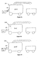
- Figures 7a to 7c schematically depict various mounting options of the apparatus 1 in a forage harvester 100 so as to form an integrated machine.
- the apparatus 1 is inserted, or built into, a forage harvester 100 in the elevator 110 (as shown in Figure 7a ), in the forage unit 105 (as shown in Figure 7b ) or in the cutter 115 (as shown in Figure 7c ) thereby enabling the integrated machine to receive, decorticate and harvest crops.
- the apparatus 1 is inserted in the elevator 110 of the forage harvester 100 as this configuration provides a highly flexible integrated machine in which the elevator/decorticating apparatus section may be readily detached from one harvesting machine and attached to another type of harvesting machine such as a combine harvester or a conventional (ie non-integrated) harvester. As such, many different types of crops may be harvested and/or decorticated with the same harvesting machine.
- a trimmer removes any leaves and the stalks are cut by the cutter 115.
- the green stalks are fed through squeeze rollers (not shown) to remove or substantially reduce the amount of gum which, if allowed to remain, would likely weaken the strength of the product fibre or be costly to remove later. It will be appreciated that while the green stalks are fed to squeeze rollers prior to decortication, they can also, or alternatively, be fed to another set of squeeze rollers following decortication.
- separated hurd passes through a slatted conveyor (not shown) while the remaining fibre is transferred to another conveyor (not shown) on which the fibre is carried to a forage unit 105.
- the output material is passed through an associated apparatus to shake and tumble the granulated hurd particles from the fibre.
- the forage harvester 100 in the embodiment shown in Figures 7a to 7c may be modified to remove/disable the chopper component usually resident inside forage machines which cut the material into short sections.
- the hemp material will already be processed by decortication upon entry into the forage unit. As such, it generally will not require further chopping by the chopper and so the chopper can be removed or adjusted out of the processing stream depending on the make and model of forage harvester.
- FIGs 8a to 8c schematically depict various mounting options of the apparatus 1 in a combine harvester 200.
- the apparatus 1 may be mounted on the combine harvester 200 in the elevator 210 between the cutter 215 and the combine unit 205.
- the combine harvester drum/rotor (not shown) is raised and rubber sweepers (not shown) mounted in the harvester ensure plant material is carried through to the straw walkers.
- the decorticating apparatus 1 can be mounted inside a mobile harvesting machine such as a combine or a forage machine. It can also be mounted inside a purpose built travelling frame or a frame designed for other crops such as rice, tea or cotton. It can also be mounted in a static mode inside a shed. Any of the mobile machines can be used in static mode inside sheds to process stored dry bales of retted or unretted hemp throughout the year or specifically at those times when field production, harvesting and processing cannot be done. Thus mobile machines can be utilised for static processing when required to do so. In the embodiment of the decorticator inside either the cutting head or the elevator, these assemblies can be mounted in static frames for static use when required. In the embodiment wherein the decorticator can be inserted temporarily inside a harvester, it could also be mounted in a static frame situation when required and leaves the harvester machines free for other work.
Description
- The present invention relates to improvements in or relating to the processing of bast crops or any crop containing an inner core surrounded by an outer fibrous layer. Examples of such crops include, but are not limited to, Cannabis sativa, better known as hemp, Kenaf, Ramie, sugar cane, nettles, Jute, Sesbania or Sisal.
- Bast crops are defined as a plant that contains a fibrous layer of bast fibres usually surrounding a pith or woody core. Some bast crops have the fibrous layers contained in bundles within the leaf of the plant. In particular, hemp contains a fibrous bast layer within the skin of the stem and branches, surrounding a woody core (herein known as hurd).
- Hemp has a number of commercial uses due to the properties of its bast and hurd fibre, which include strength, resilience and insulation. The bast fibre, which can be extracted from the outer fibrous layer of a hemp stalk, has a variety of uses and may be a constituent in the production of paper, composites, fibreboard, insulation and non-woven products. Hemp fibre also has the capacity to replace cotton, wool and synthetics as a component for textiles. With the gradual relaxation of strict legislative controls over cultivation and processing, hemp will become increasingly attractive to industry as a competitive alternative to current fibre sources.
- The stalk of a hemp plant is generally circular in cross-section, having a fibrous outer layer (skin) and an inner core (hurd). The bast fibre of the plant is located within the skin and generally, is the more valuable commodity. Hurd has applications in paper, construction and animal bedding. It is therefore desirable to separate the bast fibre from the hurd so as to maximise the options for value-adding.
- The principal constraint in processing hemp has been found to lie in separating the bast fibre from the hurd. This process is referred to herein as decortication.
- A number of proposals have been suggested for separating the bast fibre from the hurd. The principal category of decortication is mechanical separation. Of the mechanical operations, traditionally field retting, dew retting and water retting followed by scutching has been the most widely used. Field or dew retting is the process by which the hemp is laid in the field after cutting and left there for many weeks while soil born fungus and bacteria act by bio-digestion to reduce the natural glues, gums and pectins in the stem and thus reduce or remove the bonds between the inner stem core and the skin and also between the fibre bundles. Water retting is a similar biological process which is achieved by submerging the stems in water for some weeks either in tanks or in rivers and streams. After retting the stems are broken and scutched. Scutching involves beating the hemp stalk until the hurd is dislodged from the hemp skin. This step is commonly followed by a combining operation to dislodge further hurd from the beaten material and separating the fibres from one another. This method of decortication is generally very labour-intensive, time-consuming and can lead to high material losses and damage. Its application is therefore restricted to countries with low-labour cost or high production subsidies. Scutching has as a result not been found suitable for large scale economic commercial processing of hemp.
- Other mechanical decortication methods include the use of ultrasonics - which employ sound waves to generate vibrations to break the bonds between fibre and hurd and hammer-mills to shatter the stalk.
- Processing of hemp in a similar manner to that of flax has also been proposed. This method involves retting the hemp, drying and breaking the hemp stalk until the fibre separates from the hurd. Again this method is time consuming and not generally suited to large-scale commercial operation. There have also been several attempts to develop a method for decortication by processing freshly cut hemp stalks which method bypasses the need for time consuming treatment prior to separating hurd from the fibre/ skin. Patent specification
GB 1235387 GB 2205865 GB 693833 US 5465464 describe methods of processing which, while not requiring time consuming pre-treatment of the raw material, are not directed towards the processing of green or freshly cut plant stalks, particularly, green hemp stalks. - None of such prior art methods are suited to broadacre production involving both the harvesting of the hemp crop and efficiently separating the bast fibre from the hurd of the harvested stalk on a commercial scale.
- Patent specification
WO 97/45573 -
US2293056 discloses an apparatus for abstracting and treating fibers from fiber-bearing plants comprising a rotor member and an oscillating head having an upper bar, said members being provided with edged instruments adapted to co-operate in non-intersecting paths upon opposite faces of fibrous material. -
FR519207 -
WO2004/088006 discloses an apparatus for processing stalk having a fibrous outer part and an inner hurd comprising: a feeder for feeding the stalks for processing; a decorticator for decorticating the fed stalks comprising: a bending element to which the stalks are fed at a predetermined speed; a striking means that cause each stalk to bend over the bending element and to thereby fracture the hurd across the stalk and/or longitudinally split the skin at various locations along the stalk length, wherein the striking means further serves to separate the hurd from the fibrous outer part of the stalk. T - he present invention provides an effective alternative to the foregoing proposals for the processing of a bast crop, and in particular, green or non-retted bast crops. It is also specifically made so that the one system is both gentle enough to process green fresh hemp full of fluid in the field and also hard and strong enough to process hard dry hemp wherein the hurd and the gums are dry and intractable either as dry unretted hemp or dry retted hemp standing in fields or presented to the system as dry bales. The invention is capable of processing retted stems, but in a preferred embodiment, enables processing of hemp and bast crops without any need for costly, destructive, damaging, expensive and time consuming retting.
- The present invention provides an apparatus for processing green or un-retted plant stalks having a fibrous outer part and an inner section, the apparatus comprising: a toothed rotatable roller and a bending element, wherein the toothed roller includes teeth projecting from the surface of the roller; each of the teeth comprising a leading portion and a trailing portion relative to the direction of roller rotation wherein the leading portion extends a shorter radial distance from the surface of the roller compared to the trailing portion, characterised in that the bending element is positioned between 13 to 23mm below a scissor plane passing through a mid point of the leading portion of a tooth when the tooth is horizontally aligned on the toothed roller, such that on contact of the stalks with the bending element and the teeth, the stalks are caused to bend and the fibrous outer part is caused to split and the inner section, is substantially separated from the fibrous outer part.
- Preferably, the toothed roller is in the form of a cylinder or a disc (i.e., a narrow cylinder), with teeth projecting from its circumferential periphery. It will be appreciated that the longer the cylinder, the more stalks are capable of being processed simultaneously. The teeth may extend across the entire roller length or may be extend across only a portion of the roller length. Preferably the teeth extend across the substantial roller length.
- The teeth may be fabricated in two or more discrete parts, or they may each be monolithic. When fabricated in two or more discrete parts, the parts may be fastened together by any means known to persons skilled in the art such as, for example, welding and/or bolting.
- Alternatively, the toothed roller may be an integral unit and in this case, may be fabricated from a single metal piece.
- The teeth are preferably recessed within the circumference of the roller as opposed to being fastened at the point flush with the circumferential plane of the roller.
- The teeth located on the toothed roller may be of any configuration provided each tooth is able to achieve both splitting of the outer skin and scooping of the inner hurd per revolution of the cylinder. Preferably, the profile of each tooth between the leading portion and trailing portion is be stepped, a continuous curve or any configuration that allows each tooth to achieve splitting of the stalk outer skin followed by scooping of the inner hurd.
- Preferably also, the teeth dimensions (in terms of maximum length/maximum width) are within the range of about 1.0 to 1.5, more preferably about 1.2.
- In a preferred embodiment, the bending element is in the form of a hump of which the side that faces the toothed roller follows the curvature of the toothed roller.
- Desirably, the gap between the bending element and the toothed roller is adjustable. In a preferred embodiment, the gap is adjusted at about 0.5 mm to about 6 mm, preferably about 3 mm.
- In a preferred embodiment, the stalks are automatically fed to the bending element by automated means. Such automated means of feeding the stalks to the bending element may be achieved with a feeder means in the form of a pair of rollers through which the stalk(s) is/are drawn. Preferably, the toothed roller rotates at a speed of about 1600 rpm, while the feeder rollers rotate between about 100 to about 200 rpm. Most preferably, the speed of the feeder rollers is maintained at about 360 rpm while the speed of the toothed roller is maintained at about 2500 rpm.
- The present invention also provides a method of processing one or more plant stalks having a fibrous outer part (skin) and an inner section (hurd), the method comprising feeding the plant stalk(s) to the apparatus of the present invention. The stalks are in a green or in an un-retted state. The method further comprises (a) cutting the one or more stalks in a green or in an un-retted state and optionally removing any leaves, (b) optionally squeezing the one or more stalks to remove at least a partial amount of gum within the stalks, (c) separating the hurd from the skin by feeding the one or more stalks to an apparatus as described herein, (d) optionally squeezing the one or more stalks to remove at least a partial amount of gum within the stalks, and (e) drying the separated skin. Preferably, steps (d) and optionally step (e) are performed substantially immediately after the separation of the hurd and skin fractions in step (c). Preferably also, the one or more stalks are cut or harvested using a suitable cutting head and the apparatus according to the present invention mounted on a forage or combine harvester.
- The toothed roller may be fabricated from a range of materials, for example, from high density polymers or from metals such as hardened steel. As the one or more plant stalks are fed to the apparatus, the teeth located on the toothed roller each successively contact one or more plant stalks. It will be appreciated that high impact forces may be generated upon contact of each of the teeth with a plant stalk. The use of stronger materials to fabricate the toothed roller allows higher impact forces to be withstood by the toothed roller which are generated through contact of the plant stalk(s) with the teeth.
- The toothed roller may be in the form of a cylinder or a disc (i.e., a narrow cylinder), with teeth projecting from its circumferential periphery. It will be appreciated that the longer the cylinder, the more stalks are capable of being processed simultaneously. The teeth may extend across the entire roller length or may be extend across only a portion of the roller length. Preferably the teeth extend across the substantial roller length.
- The teeth may be fabricated in two or more discrete parts, or they may each be monolithic. When fabricated in two or more discrete parts, the parts may be fastened together by any means known to persons skilled in the art such as, for example, welding and/or bolting.
- Alternatively, the toothed roller may be an integral unit. In this case, the toothed roller may be fabricated from a single metal piece wherein the teeth are cut out by the use of a lathe.
- When the toothed roller is fabricated from a discrete cylinder and teeth, it will be appreciated that the connection points between the cylinder and the teeth will be weakened stress points which are subject to failure upon contact of the teeth with the one or more plant stalks. In order to strengthen the toothed roller, the teeth may be recessed within the circumference of the roller as opposed to being fastened at the point flush with the circumferential plane of the roller. In this way, part, or most of the impact force is transferred to the cylindrical section of the roller, as opposed to being handled by the teeth alone. This allows greater impact forces to be withstood by the apparatus upon sequential contact of the one or more plant stalks with the teeth as the roller revolves.
- The teeth located on the toothed roller may comprise any configuration provided each tooth is able to achieve both splitting of the outer skin and scooping of the inner hurd per revolution of the cylinder. The profile of each tooth between the leading portion and trailing portion may be stepped, a continuous curve or any configuration that allows each tooth to achieve splitting of the stalk outer skin followed by scooping of the inner hurd.
- It will be appreciated that the longer the teeth, the lower the impact force able to be withstood by the teeth before failure or deformation when contacted with the plant stalks. As such, the teeth dimensions (in terms of maximum length/maximum width) are preferably within the range of 1.0 to 1.5, more preferably 1.2.
- It is also desirable to have teeth edges that are sharp enough to assist in the splitting of the outer skin and also in scooping the exposed hurd. In this way, more efficient fibre/hurd separation, and hence, decortication, is likely to be achieved.
- Preferably, the stalk(s), upon impact with one or more teeth, is/are split substantially longitudinally, and not transversely, along the stalk length. This result may be achieved, in part, by controlling the sharpness of the bending element over which the stalk(s) is/are bent. It will be appreciated that if the bending element edge is too sharp, this will result in "scissor" action - that is, the stalks will be cut transversely along the stalk length resulting in the stalk being cut in a discrete number of pieces. As such, little or no fibre/hurd separation will occur resulting in little or no decortication. It is desirable, therefore, to have a bending element which is substantially blunt, yet shaped so as allow the stalk(s) to bend, yet not be cut, when contacted by the teeth of the toothed roller.
- The efficiency of decortication is controlled by the location of the bending element in relation to the toothed roller. It has been determined that positioning of the bending element below (as opposed to directly on) the plane defined by the teeth when horizontally aligned on the roller (hereinafter referred to as the "scissor plane"), provides maximum scoop of the hurd and therefore, maximum decortication efficiency. That is, the scissor action is minimised when the bending element is positioned below the scissor plane. The bending element may be positioned at various distances below the defined scissor plane, the chosen position depending on, for example, the age, width or variety of the stalks to be processed. By virtue of being able to adjust the position of the bending element, the apparatus operation can be optimised for various types of stalk. So as to further assist in minimising scissor action and therefore maximise decortication efficiency, the toothed roller position may also be adjustable in addition to the position of the bending element. The bending element is positioned about 13-23 mm below the scissor plane. It will be appreciated that the positioning of the bending element, in addition to other system elements such as, for example, the toothed roller, will vary depending on the plant type and crop condition on the day of harvesting.
- The bending element may be a plate, or form part of a plate, or the like. It has been determined that the shape of the bending element also affects the level of scoop that the one or more teeth are able to achieve through the secondary strike. As such, the shape of the bending element also affects the decortication efficiency. In a preferred embodiment, the bending element is in the form of a hump of which the side that faces the toothed roller follows the curvature of the toothed roller. In this way, maximum scoop of the hurd by the teeth is achieved thereby resulting in maximum decortication efficiency.
- The efficiency of decortication may also be controlled by the location of the bending element in relation to the distance from the toothed roller. For instance, if the gap is too small for the specific crop in the conditions on the day of processing, then the skin will be cut and damaged and rendered useless. Conversely, if the gap is too big for the specific crop on the day of processing, the hurd chips will be too large or become strips.
- It has been determined that positioning of the bending element should be able to be adjusted so that the toothed roller can come to within about 0.5 mm of the bending element and also be able to be adjusted away from the bending element. In some dry crops or crops with thin skins, it is desirable to adjust the toothed roller as close as about 0.5 mm. In other crops it has been desirable to increase that gap between the toothed roller and the bending element to as much as about 6 mm. The most usual crop range is decorticated best at about 3 mm. As such, the gap between the bending element and the toothed roller is preferably adjusted at about 0.5 mm to about 6 mm, preferably about 3 mm.
- In order to achieve the adjustment of the gap between the bending element in relation to the toothed roller, in one embodiment, the bending element and linked input roller pair may be integrated on a sliding assembly. In another embodiment the frame holding the toothed roller assembly is able to pivot and be raised or lowered against a fixed bending bar assembly and thus increase or decrease the gap.
- The stalk(s) may be fed to the bending element either manually or by automated means. In a preferred embodiment, the stalk(s) are automatically fed and guided to the bending element by feeder means in the form of a pair of rollers through which the stalk(s) is/are drawn. The feeder rollers may include a cylindrical surface that is textured so as to increase the grip of feeder rollers on the stalks. Such texturing may be provided by a series of projections extending along the roller length.
- When feeder rollers are employed, a high grip of the stalks by the feeder rollers is desirable, as the feeder rollers in addition to guiding the entry of the stalks into the apparatus, also control the rate at which the stalk material enters the apparatus. As the toothed roller normally rotates at a much greater speed compared to the rate at which the stalks are fed to the bending element, it is possible that without proper feed control, the stalks will be forced through the apparatus at the rate of the toothed roller which would result in a lower decortication efficiency which is undesirable.
- The feeder rollers may also serve to compress, and hence condition (i.e., soften, crack etc.) the stalk fibrous outer part prior to entry into the decorticator, particularly when the bast crop is green or conversely, when dry and hard.
- The speed of the toothed roller and/or the feeder rollers is preferably adjustable and able to be controlled. Preferably, the toothed roller rotates at a much greater speed compared to the speed of the feeder rollers (and hence the entry speed of the stalk into the apparatus). The rotational speed at which the toothed roller is set depends on the speed at which the stalk is fed to the bending element and also on the type of crop, the age of the crop and the average stalk stem thickness. If, for instance, the time segments between strikes of the stalks are too long, long unsplit sections remain between fractures, resulting in inefficient separation of hurd from the skin at decortication or from the decorticated skin mass. In a preferred embodiment, the toothed roller rotates at a speed of about 1600 rpm, while the feeder rollers rotate between about 100 to about 200 rpm. Most preferably, the speed of the feeder rollers is maintained at about 360 rpm while the speed of the toothed roller is maintained at about 2500 rpm. These speeds can be increased once the correct ratio for the specific input material has been established. However, persons skilled in the art will appreciate that such speeds are based on the processing of an average hemp crop having reached the stage of senescence (hereafter known as flowering), still standing and alive (green fresh) but not having as yet formed immature seed. This average crop is seen to be within a period of 4 weeks from the beginning of flowering with an average stem width in the range of 8-18 mm. It will be appreciated that the weather and crop type and variety can cause considerable variation in processing speeds. As such the right ultimate speed of the toothed roller and the ratio of operation dictating the ideal speed of the feeder rollers will likely be determined on the day of harvesting.
- The method of the present invention can be conducted via an apparatus that is part of either a static or non-static processing system. An example of each processing system is static modules based in a warehouse to process dry retted or dry un-retted bales or internal modules based within a harvesting frame for fresh 'green' infield decortication.
- The method according to the present invention may include the additional prestep of observing the growth pattern of the plant stalks in the field, whereupon harvesting and decortication of the stalks may be commenced at a predetermined phase of growth of the plant. The stalk may be fresh 'green', dry, semi-dry, retted or non-retted.
- It has been observed that the strength of the bond between the fibre and hurd changes at various stages of growth in the plant. Preferably, harvesting and decortication are commenced when the plant is green, also known as freshly cut or fresh 'green'. The fibre of the stalk preferably remains sufficiently fine for fine textile use, that is to say, preferably just prior to pollen release up to seed set. The plant stalk may be harvested by cutting and removal of leaves using known methods. In the case of hemp, the stalks may be harvested at 50 to 110 days maturity. Preferably the hemp is harvested before the inner hurd thickens dramatically (flowering), prior to seedset, before the adhesives between the hurd and outer fibres harden and lignify and most preferably at the point of flowering is the preferred indicator of a suitable time to harvest a large crop for use in accordance with the present invention for best textile fibre or strongest non-woven fibre. The cut end at the base of the plant stalk is referred to herein as the butt end.
- The apparatus may be suitable for use as a single component in a fibre processing arrangement or a plurality of apparatuses in accordance with the invention may be incorporated into a processing system for parallel processing of the plurality of stalks. For example, the apparatus in accordance with the invention may be used in isolation to process stored, dry, retted or semi-retted, or unretted bast bales or may be used in combination with a harvester to process fresh 'green' stalks or also in combination with a harvester to process mature stalks which have been stripped of their seed but left standing. In some cases where the hemp, for example, has grown through to mature seed, the stems may be stripped of seed, cut and windrowed. These stems may then be fed into the system. Such crops are known as "dual crops" as they give both seed and fibre. The fibre is very useful but usually of a lower quality and less fine than that obtained from green processed fibre crops.
- Although the processing of dry stalks requires a higher input of energy than processing of fresh green stalks, it has the advantage that processing of such material is independent of the season; that is, stored dried bales of bast stalks may be processed throughout the year. Preferably, if dried gum is processed, dried un-retted stalks are used, however this is not essential. Processing of such dried material in accordance with the present invention will shatter off substantially all of the gum as dry dust and powder which may be collected and have commercial use and value. For example, dried gum dust or powder may be used as glue to adhere hurd parts together in fibre boards etc.
- Due to the lower input of energy required to process fresh harvested green stalk, such material is preferably processed in accordance with the present invention. Harvesting of green stalk is preferably commenced before the "adhesive" between the fibrous outer layer and the inner core dries. Normally this is within two hours of harvesting but preferably immediately after harvesting. Most preferably processing commences not more than 15 minutes after harvesting. Commencement of processing within two minutes of harvesting is particularly preferred.
- The apparatus of the present invention may further include a means for degumming or partial degumming of the skins (fibre) of fresh 'green' stalks. The degumming may be achieved by applying pressure to the skins thereby causing fluid from the skin to be leached and reducing such products as gums, pectins, water and phloem sap from the skin material. Such leached products may be collected and used in other processes or for other purposes such as, for example, glue and the present invention extends to compositions or formulations comprising a gum, pectin or leachate extracted from a bast fibre skin, eg. a glue or adhesive formulation.
- The means for applying pressure to the skin so as to leach out fluids may include one or more smooth and/or toothed roller(s). Such means also assists in the conditioning of the skin and subsequent fibres.
- The apparatus of the present invention may further include a means for providing an airflow, the air flow being such as to entrain at least part of the separated hurd. The use of means to provide airflow is particularly desired in the processing of a dry stalk. The means for providing airflow may be an air blower, compressor or the like. Airflow may be provided by an alteration to the cavities of the toothed rollers and shell guards to create a positive draw of air into the decortication process. Preferably, such means are able to induce high velocity airflow and may carry water droplets, mist or vapour to increase the air-flow effect and/or control the moisture content. Enzymes may also be introduced to the system to start the process of degumming. Release agents such as hemp oil or linseed oil may also be added to the air to avoid sticking of the stalk component to parts of the apparatus.
- The apparatus may also comprise a slatted conveyor which serves to transport the separated hurd and skin fractions from the apparatus; that is, the separated hurd may fall through a slatted conveyor into a collection bag while the separated fibrous outer part may be conveyed by the conveyor to a separate collection bag located at the end of the conveyor. Preferably, the air flow also assists in forcing the hurd segments downwards through the slats of the slatted conveyor, whereas the fibre is conveyed on the conveyor. The separated hurd and fibrous outer fractions are then able to be separately collected for further processing.
- The apparatus may also be associated with a separation unit which shakes and tumbles the decorticated fibre to ensure the more complete separation and removal of the dislodged and shattered hurd fragments. This associated apparatus can be fabricated utilising straw-walkers and/or tumbling mess cages. In some configurations these can be found inside combine harvesters.
- The apparatus may be associated with other components for pre-processing the stalks for entry into the apparatus, for example, a primary stripping stage to remove leaves and/or braches or subjecting the stalks to chemical pretreatment to remove gum, or to lessen the bond strength of the gum between the skin and hurd, thereby assisting decortication. The stems may be passed through squeeze rollers prior to decortications in order to remove fluids. The apparatus of the invention may be associated with means for further processing of the fibre produced by the apparatus, for example chemical treatment means. Depending on the ultimate use of the fibre, the removal of any residual gum may be desired. As such, the decorticated fibre may be subjected to further treatment to remove any residual gums and stabilise organic activities, eg. by the addition of suitable chemicals and/or drying the fibre.
- The apparatus may further include a vacuum extraction arrangement for extraction of the hurd after it exits the decorticator.
- A particular problem associated with the processing of the bast fibre plants is that the bast fibre wraps around the means for striking the stalk(s) (for example, the toothed roller). This may be avoided through the inclusion of one or more guard means to prevent fibre wrapping around the toothed roller. Preferably the guard means is/are one or more shell guards.
- Depending on the size of the apparatus and its implementation, the toothed roller may be powered from a harvester for example, or alternatively, be self-powered by a petrol engine, diesel engine or electric motor for example. Preferably, the feeder rollers are powered by one or more separate drive motors but should ideally be geared together to ensure they run at the same speed. Preferably also, the apparatus comprises some type of bag-system or bulk handling system at one or more output ends, which serves to collect the processed and separated hurd and fibre fractions. The liquid may also be collected.
- The fibre may be subjected to an enzymic treatment as described in
PCT/AU02/00931 - A plant stalk to be processed according to processing methods and apparatus of the present invention may be a hemp stalk. In particular, the preferred hemp is that of Cannabis sativa L. and species thereof. Other plant stalks envisaged for processing in accordance with the present invention, include Kenaf, Ramie, Jute, Sesbania or Sisal., sugar cane, bamboo and nettles.
- "Scissor action" as used herein is intended to refer to the process of cutting the stalks substantially in the transverse direction along the stalk length thereby resulting in discrete stalk pieces in which inefficient or no fibre/hurd separation is achieved.
- "Scissor plane" as used herein refers to the plane defined by a tooth of the toothed roller when horizontally aligned.
- The invention will now be described in further detail with reference to the following non-limiting preferred embodiment and the accompanying figures.
-
-
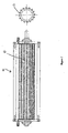
Figure 1 is a side and cross-sectional view of the toothed roller according to a preferred embodiment of the invention. -
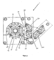
Figure 2 is a cross sectional view of the toothed roller ofFigure 1 in relation to the feeder rollers and bending element. In particular, the position of the feeder rollers is shown in an alternative position that allows access to the toothed roller and bending element.Figure 2 also shows a method by which the distance between the teeth and bending element is adjusted. -
Figure 3 is a cross sectional view of the apparatus according to an alternative embodiment of the invention. Shown in particular is an alterative method by which the distance between the teeth and bending element to be adjusted. -
Figure 4 is an exploded view of a section of the toothed roller ofFigure 1 shown in cross section. -
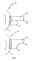
Figure 5 is an exploded view of a section ofFigure 2 . -
Figure 6 depicts two alternative tooth configurations, the first configuration being in accordance with the preferred tooth configuration as shown inFigures 1 to 5 . -
Figure 7 depicts a schematic representation of an integrated machine in accordance with another embodiment in which the apparatus ofFigure 2 is integrated with a forage harvester. In particular, figures (a) to (c) depict various mounting options of the apparatus within the forage harvester. -
Figure 8 depicts a schematic representation of an integrated machine in accordance with another embodiment in which the apparatus ofFigure 2 is integrated with a combine harvester. In particular, figures (a) to (c) depict various mounting options of the apparatus within the combine harvester. - Referring to
figure 1 , in a first embodiment, thetoothed roller 10 is shown in side and cross sectional views. As can be seen from this figure, theteeth 13 extend along the length of the roller and are spaced substantially uniformly around the roller circumference. Such substantially uniform spacing of the teeth around the circumference assists in providing uniform decortication; that is, the stalks (not shown) are bent over the bending element (seeFigure 2 ) at regular intervals resulting in more efficient splitting of the outer fibrous part of the stalk and scooping of the inner hurd. -
Figure 2 shows the apparatus 1 in cross sectional view. Thetoothed roller 10 comprisingteeth 13 embedded within the roller circumferential surface is disposed next to the bendingelement 15 at a distance sufficient to decorticate the stalk (not shown). It will be appreciated that the distance between theteeth 13 and the bendingelement 15 is adjustable as required to achieve efficient decortication dependant on the age and type of plant stalk to be processed. In order to control this distance, the apparatus 1 comprises a bending element adjusting means 17 in this embodiment. Other adjusting means can be applied to ensure that the gap between the teeth of the toothed roller and the curved hump or bending element can be varied.Figure 3 shows an alternative embodiment in which the distance between theteeth 13 and the bendingelement 15 may be adjusted. In this embodiment, the position of wholetoothed roller 10 is able to be adjusted by virtue of thescrew 18, while the bendingelement 15 is fixed in relation to thefeeder rollers 20. - In the preferred embodiment, the bending
element 15 is in the form of a hump of which the surface facing thetoothed roller 10 is curved. Such curvature within the bendingelement 15 assists in achieving better scooping of the inner hurd with the roller teeth and therefore better fibre/hurd separation. The apparatus further comprises shell guards 21 which assist in minimising "wrap around" of the fibre and/or separated hurd about thetoothed roller 10 or thefeeder rollers 20. Minimisation of fibre "wrap around" is also assisted byblades 25 which cut fibre entrained by the motion of thetoothed roller 10 or thefeeder rollers 20. -
Figure 2 , also shows an alternative position for thefeeder rollers 20. Thisalternative position 200 of thefeeder rollers 20 allows ready access to thehump 15 andtoothed roller 10 for maintenance and cleaning of the apparatus. -
Figure 4 shows an exploded view of a section of the toothed roller. As can be seen from this figure, theteeth 13 are formed of two parts that are welded and/or bolted together to form a single unit.Figure 4 and5 also shows how theteeth 13, are recessed atpoint 14 into the roller cylinder 11. Such recessing serves to strengthen the toothed roller (i.e., minimise the impact force on the teeth as they contact the stalk) by transferring most, or part, of the impact force from theteeth 13 to the roller cylinder 11. - Referring now to
Figure 5 , an exploded view of a section of the apparatus in accordance with the preferred embodiment is shown. In particular, the direction in which thetoothed roller 10 revolves is shown by the hollow arrow. The speed of thetoothed roller 10 is comparatively much faster than that of thefeeder rollers 20. The typical speed at which thetoothed roller 10 revolves is about 1600 rpm, however, it will be appreciated that this speed depends on the speed of thefeeder rollers 20 and also the type and age of plant stalk that is to be processed. Typically, the feeder rollers revolve at about 360 rpm. -
Figure 5 also shows the position of the bendingelement 15 in relation to the scissor plane (X-X) and thetoothed roller 10. As can be seen, the bendingelement 15 is positioned below the scissor plane. It has been determined that such positioning of the bendingelement 15 below the scissor plane (X-X) reduces the stalk being directly struck by eachtooth 13 and assists in achieving greater scoop of the inner hurd during the secondary strike delivered by eachtooth 13. As such, more efficient fibre/hurd separation is achieved compared to the separation observed when the bendingelement 15 is positioned directly on the scissor plane (X-X). -
Figure 5 also shows a bold arrow which indicates the entry point of the stalk(s) (not shown) to the apparatus. The direction in which the stalks travel after being fed to the bendingelement 15 by thefeeder rollers 20 is also indicated by the arrow shown in dotted outline. As can be seen, the stalks are bent over the bendingelement 15 when contacted by the teeth. By virtue of the leadingportion 22 and the trailingportion 23, eachtooth 13 is able to substantially simultaneously split the stalk outer fibre and scoop the inner hurd. -
Figure 6 shows two alternative configurations of theteeth 13. The first configuration shown is in accordance with the preferred embodiment of the invention with a stepped profile between leadingportion 22 and the trailingportion 23. In this configuration, the teeth are formed of two parts which are fastened together by, for example, welding and/or bolting. The alternative tooth configuration shows a continuous profile between leadingportion 22 and trailingportion 23. This alternative tooth configuration would be expected to be stronger due to no sharp corners (and therefore weakened stress points) in the curved profile between the leadingportion 22 and trailingportion 23. The alternative tooth configuration would also be expected to be stronger by virtue of its monolithic structure. -
Figure 6 also clearly shows (in hatching) how theteeth 13 are recessed or embedded within the toothed roller cylinder 11. This allows higher impact loads to be withstood by the teeth as they strike the stalk(s) due to load transfer of the impact force from theteeth 13 to the roller cylinder 11. - Preferably, all of the component parts of the apparatus are fabricated from a material able to handle high impact loads such as toughened steel. In particular, and with reference to
Figure 2 , the components of the decorticator that need to be toughened in order to deal with high impact loads exerted are theblades 25, the bendingelement 15, the teeth 13 (which comprise of two sections, leadingportion 22 and trailingportion 23 as referred to inFigure 6 ) andfeeder rollers 20. - In a further embodiment of the invention, the apparatus 1 is inserted into a harvesting machine, such as a combine or forage harvester, thereby allowing crops such as hemp to be decorticated and harvested with a single integrated machine. It will be appreciated that the apparatus 1 of the present invention is able to be inserted into a harvester by virtue of the fact that it is front loading and can be made in a suitable size and configuration to be conveniently inserted as a unit, or built in as required by the size and make of the host mobile machine.
-
Figures 7a to 7c schematically depict various mounting options of the apparatus 1 in aforage harvester 100 so as to form an integrated machine. As can be seen fromFigures 7a to 7c , the apparatus 1 is inserted, or built into, aforage harvester 100 in the elevator 110 (as shown inFigure 7a ), in the forage unit 105 (as shown inFigure 7b ) or in the cutter 115 (as shown inFigure 7c ) thereby enabling the integrated machine to receive, decorticate and harvest crops. Preferably, the apparatus 1 is inserted in theelevator 110 of theforage harvester 100 as this configuration provides a highly flexible integrated machine in which the elevator/decorticating apparatus section may be readily detached from one harvesting machine and attached to another type of harvesting machine such as a combine harvester or a conventional (ie non-integrated) harvester. As such, many different types of crops may be harvested and/or decorticated with the same harvesting machine. - In the integrated forage harvester of
Figures 7a to 7c , a trimmer (not shown) removes any leaves and the stalks are cut by thecutter 115. The green stalks are fed through squeeze rollers (not shown) to remove or substantially reduce the amount of gum which, if allowed to remain, would likely weaken the strength of the product fibre or be costly to remove later. It will be appreciated that while the green stalks are fed to squeeze rollers prior to decortication, they can also, or alternatively, be fed to another set of squeeze rollers following decortication. Once the stalks pass through the apparatus 1, separated hurd passes through a slatted conveyor (not shown) while the remaining fibre is transferred to another conveyor (not shown) on which the fibre is carried to aforage unit 105. Alternatively the output material is passed through an associated apparatus to shake and tumble the granulated hurd particles from the fibre. - The
forage harvester 100 in the embodiment shown inFigures 7a to 7c , may be modified to remove/disable the chopper component usually resident inside forage machines which cut the material into short sections. In the processing of hemp, for example, according to the method of the invention, the hemp material will already be processed by decortication upon entry into the forage unit. As such, it generally will not require further chopping by the chopper and so the chopper can be removed or adjusted out of the processing stream depending on the make and model of forage harvester. -
Figures 8a to 8c schematically depict various mounting options of the apparatus 1 in acombine harvester 200. Like the forage harvester depicted inFigures 7a to 7c , the apparatus 1 may be mounted on thecombine harvester 200 in theelevator 210 between thecutter 215 and thecombine unit 205. In this configuration, the combine harvester drum/rotor (not shown) is raised and rubber sweepers (not shown) mounted in the harvester ensure plant material is carried through to the straw walkers. - As discussed above the decorticating apparatus 1 can be mounted inside a mobile harvesting machine such as a combine or a forage machine. It can also be mounted inside a purpose built travelling frame or a frame designed for other crops such as rice, tea or cotton. It can also be mounted in a static mode inside a shed. Any of the mobile machines can be used in static mode inside sheds to process stored dry bales of retted or unretted hemp throughout the year or specifically at those times when field production, harvesting and processing cannot be done. Thus mobile machines can be utilised for static processing when required to do so. In the embodiment of the decorticator inside either the cutting head or the elevator, these assemblies can be mounted in static frames for static use when required. In the embodiment wherein the decorticator can be inserted temporarily inside a harvester, it could also be mounted in a static frame situation when required and leaves the harvester machines free for other work.
Claims (8)
- An apparatus (1) for processing green or un-retted plant stalks having a fibrous outer part and an inner section, the apparatus comprising:a toothed rotatable roller (10) and a bending element (15), wherein the toothed roller includes teeth (13) projecting from the surface of the roller (10);each of the teeth (13) comprising a leading portion (22) and a trailing portion (23) relative to the direction of roller rotation wherein the leading portion (22) extends a shorter radial distance from the surface of the roller (10) compared to the trailing portion (23),characterised in that the bending element (15) is positioned between 13 to 23mm below a scissor plane (X-X) passing through a midpoint of the leading portion (22) of a tooth (13) when the tooth (13) is horizontally aligned on the toothed roller (10), such that on contact of the stalks with the bending element (15) and the teeth (13), the stalks are caused to bend and the fibrous outer part is caused to split and the inner section, is substantially separated from the fibrous outer part.
- An apparatus (1) according to claim 1, characterised in that the position of the bending element (15) in relation to the toothed roller (10) defines a gap which is adjustable by movement of the bending element (15), the toothed roller (10) or both.
- An apparatus (1) according to claim 1 or 2, characterised in that the profile of each tooth (13) between the leading portion (22) and trailing portion (23) is stepped.
- An apparatus (1) according to claim 2, characterised in that the gap between the toothed roller (10) and the bending element (15) is adjusted from about 0.5mm to about 6mm.
- A method of processing plant stalks having a fibrous outer part and an inner section, characterised in that the method comprises cutting the plant stalks when in a green or in an un-retted state; feeding the plant stalks into an apparatus (1) that comprises:a toothed rotatable roller (10) and a bending element (15), wherein the toothed roller includes teeth (13) projecting from the surface of the roller (10),each of the teeth (13) comprising a leading portion (22) and a trailing portion (23) relative to the direction of roller rotation wherein the leading portion (22) extends a shorter radial distance from the surface of the roller (10) compared to the trailing portion (23);the bending element (15) being positioned between 13 to 23mm below a scissor plane (X-X) passing through a midpoint of the leading portion (22) of a tooth (13) when the tooth (13) is horizontally aligned on the toothed roller (10);rotating the roller (10) so that the plant stalks being fed into the apparatus (1) come into contact with the bending element (15) and the teeth (13), which causes the stalks to bend and the fibrous outer part to split and the inner section is substantially separated from the fibrous outer part; and thereafter drying the separated fibrous outer part.
- A method according to claim 5, characterised by squeezing the stalks to remove at least a partial amount of gum within the stalks prior to either processing the stalks in the apparatus or drying the separated fibrous outer part.
- A method according to claim 5 or 6, including feeding the stalks into the apparatus (1) by a pair of feed rollers (20), characterised in that the toothed roller (10) rotates at a speed of about 1600 rpm, and the feed rollers (20) rotate between about 100 to about 200 rpm.
- A method according to claim 5 or 6, including feeding the stalks into the apparatus (1) by a pair of feed rollers (20), characterised in that the toothed roller (10) rotates at a speed of about 2500 rpm, and the feed rollers (20) rotate at about 360 rpm.
Applications Claiming Priority (2)
| Application Number | Priority Date | Filing Date | Title |
|---|---|---|---|
| AU2005901132A AU2005901132A0 (en) | 2005-03-09 | Apparatus and method for processing of plant material | |
| PCT/AU2006/000317 WO2006094359A1 (en) | 2005-03-09 | 2006-03-09 | Apparatus and method for processing of plant material |
Publications (3)
| Publication Number | Publication Date |
|---|---|
| EP2018447A1 EP2018447A1 (en) | 2009-01-28 |
| EP2018447A4 EP2018447A4 (en) | 2011-04-13 |
| EP2018447B1 true EP2018447B1 (en) | 2015-01-14 |
Family
ID=36952882
Family Applications (1)
| Application Number | Title | Priority Date | Filing Date |
|---|---|---|---|
| EP06704990.8A Not-in-force EP2018447B1 (en) | 2005-03-09 | 2006-03-09 | Apparatus and method for processing of plant material |
Country Status (5)
| Country | Link |
|---|---|
| EP (1) | EP2018447B1 (en) |
| AU (1) | AU2006222558B2 (en) |
| HU (1) | HUE025142T2 (en) |
| NZ (1) | NZ590509A (en) |
| WO (1) | WO2006094359A1 (en) |
Cited By (2)
| Publication number | Priority date | Publication date | Assignee | Title |
|---|---|---|---|---|
| CN107338482A (en) * | 2016-10-18 | 2017-11-10 | 桐乡守敬应用技术研究院有限公司 | A kind of bluish dogbane handling process |
| US11873579B1 (en) | 2022-07-29 | 2024-01-16 | Tom Pires | Hemp separation methods and apparatus |
Families Citing this family (4)
| Publication number | Priority date | Publication date | Assignee | Title |
|---|---|---|---|---|
| CN102634853B (en) * | 2012-04-28 | 2014-04-02 | 魏己 | Double-drum hemp decorticator |
| RU173345U1 (en) * | 2016-12-30 | 2017-08-22 | общество с ограниченной ответственностью "АГРОЛЁН-ИНВЕСТ" | DEVICE FOR PROCESSING ANY STEM IN THE FIELD |
| CN113279068B (en) * | 2021-04-07 | 2023-08-08 | 重庆市戏水族服饰科技有限公司 | Knocking type fabric component fiber extraction device |
| RO137209A2 (en) | 2021-07-22 | 2023-01-30 | Institutul Naţional De Cercetare-Dezvoltare Pentru Maşini Şi Instalaţii Destinate Agriculturii Şi Industriei Alimentare | Hemp fiber processing equipment |
Citations (3)
| Publication number | Priority date | Publication date | Assignee | Title |
|---|---|---|---|---|
| DE44861C (en) * | p, FRICKE in Berlin, Neue Grünstr. 39 | Machine for the mechanical processing of fibrous parts of plants | ||
| US2551128A (en) * | 1945-07-09 | 1951-05-01 | Waldo | Decorticating process |
| WO2004088006A1 (en) * | 2003-03-30 | 2004-10-14 | Fibre Laboratory Pty Ltd | Apparatus and method for processing of plant material |
Family Cites Families (10)
| Publication number | Priority date | Publication date | Assignee | Title |
|---|---|---|---|---|
| FR519207A (en) | 1920-06-22 | 1921-06-07 | Dewaele Et Schotte | Automatic flax grinding and scutching machine |
| DE600103C (en) * | 1933-02-22 | 1934-07-14 | Ernst Luchsinger Dipl Ing | Fiber processing machine with beating drum and counter holding means |
| US2293056A (en) | 1938-04-26 | 1942-08-18 | Frederick P Gardner | Apparatus for abstracting and preparing fibers from fiber-bearing plants |
| US2719332A (en) * | 1952-06-03 | 1955-10-04 | Florida Ind Lab Inc | Decorticator |
| FR2535738B1 (en) * | 1982-11-04 | 1985-10-25 | Inst Textile De France | PROCESS FOR SCRAPING FLAX AND MATERIAL FOR ITS IMPLEMENTATION |
| NL8901226A (en) * | 1989-05-17 | 1990-12-17 | Inst Voor Bewaring | Apparatus for processing flax straw, as well as flax straw opener and drum therefor. |
| DE4119749A1 (en) * | 1991-06-15 | 1992-12-17 | Claas Ohg | METHOD FOR REMOVING FLAX AND FLAT PREPARATION MACHINE FOR CARRYING OUT THIS METHOD |
| JP2501513B2 (en) * | 1992-07-03 | 1996-05-29 | 株式会社アスク | Bamboo fiber manufacturing method |
| AUPO010496A0 (en) | 1996-05-24 | 1996-06-20 | Mierisch, Charles George | Improvements in or relating to harvesting |
| CA2374640A1 (en) * | 2000-03-21 | 2001-09-27 | American Tool Companies, Inc. | Metal-cutting saw blade having strengthened gullet and negative tooth rake |
-
2006
- 2006-03-09 HU HUE06704990A patent/HUE025142T2/en unknown
- 2006-03-09 NZ NZ59050906A patent/NZ590509A/en not_active IP Right Cessation
- 2006-03-09 EP EP06704990.8A patent/EP2018447B1/en not_active Not-in-force
- 2006-03-09 AU AU2006222558A patent/AU2006222558B2/en active Active
- 2006-03-09 WO PCT/AU2006/000317 patent/WO2006094359A1/en active Application Filing
Patent Citations (3)
| Publication number | Priority date | Publication date | Assignee | Title |
|---|---|---|---|---|
| DE44861C (en) * | p, FRICKE in Berlin, Neue Grünstr. 39 | Machine for the mechanical processing of fibrous parts of plants | ||
| US2551128A (en) * | 1945-07-09 | 1951-05-01 | Waldo | Decorticating process |
| WO2004088006A1 (en) * | 2003-03-30 | 2004-10-14 | Fibre Laboratory Pty Ltd | Apparatus and method for processing of plant material |
Cited By (2)
| Publication number | Priority date | Publication date | Assignee | Title |
|---|---|---|---|---|
| CN107338482A (en) * | 2016-10-18 | 2017-11-10 | 桐乡守敬应用技术研究院有限公司 | A kind of bluish dogbane handling process |
| US11873579B1 (en) | 2022-07-29 | 2024-01-16 | Tom Pires | Hemp separation methods and apparatus |
Also Published As
| Publication number | Publication date |
|---|---|
| HUE025142T2 (en) | 2016-03-29 |
| EP2018447A1 (en) | 2009-01-28 |
| WO2006094359A1 (en) | 2006-09-14 |
| EP2018447A4 (en) | 2011-04-13 |
| NZ590509A (en) | 2012-08-31 |
| AU2006222558B2 (en) | 2012-04-12 |
| AU2006222558A1 (en) | 2006-09-14 |
Similar Documents
| Publication | Publication Date | Title |
|---|---|---|
| EP2018447B1 (en) | Apparatus and method for processing of plant material | |
| US9107342B2 (en) | Method for harvesting bast plants | |
| US7520214B2 (en) | Method and machine for packing fibrous plants into balls especially common flax, hemp plant and sisal | |
| WO1997045573A1 (en) | Harvesting and processing green fibrous plant stalks | |
| CN205946586U (en) | Corn ear and stalks left after threshing stalk reap, beat a bundle all -in -one | |
| Munder et al. | Processing of bast fiber plants for industrial application | |
| RO134839A2 (en) | Equipment for decorticating hemp stalks for hemp bundle | |
| US7073315B2 (en) | Apparatus for and method of harvesting cotton | |
| EP0122769A2 (en) | Separation of fibres from vegetable matter | |
| WO2004088006A1 (en) | Apparatus and method for processing of plant material | |
| EP1155172B1 (en) | Apparatus and method for processing green fibrous plant stalks | |
| WO2011086564A1 (en) | Automatic high speed jute ribboning machine and the process thereof | |
| Anthony | Separation of fiber from seed flax straw | |
| AU2004225900A1 (en) | Apparatus and method for processing of plant material | |
| US20230128312A1 (en) | Bast ribbon processing apparatus and method of decortication | |
| CN110916225A (en) | Production system of hemp crops | |
| AU737657B2 (en) | Harvesting and processing green fibrous plant stalks | |
| WO2001075198A1 (en) | Processing fibre crops | |
| US5379579A (en) | Method for harvesting broom corn and apparatus therefor | |
| Anthony | Decortication of straw from seed flax | |
| US11519099B1 (en) | Bast stalk alignment feed and decortication system | |
| US11873579B1 (en) | Hemp separation methods and apparatus | |
| EP1227177A1 (en) | Fibre separation | |
| WO2022251418A1 (en) | Biomass feedstock recovery equipment and processes | |
| Anthony | New technology to separate fiber and shive from seed flax straw |
Legal Events
| Date | Code | Title | Description |
|---|---|---|---|
| PUAI | Public reference made under article 153(3) epc to a published international application that has entered the european phase |
Free format text: ORIGINAL CODE: 0009012 |
|
| 17P | Request for examination filed |
Effective date: 20081002 |
|
| AK | Designated contracting states |
Kind code of ref document: A1 Designated state(s): AT BE BG CH CY CZ DE DK EE ES FI FR GB GR HU IE IS IT LI LT LU LV MC NL PL PT RO SE SI SK TR |
|
| AX | Request for extension of the european patent |
Extension state: AL BA HR MK YU |
|
| A4 | Supplementary search report drawn up and despatched |
Effective date: 20110316 |
|
| RIC1 | Information provided on ipc code assigned before grant |
Ipc: D01B 1/22 20060101ALI20110310BHEP Ipc: D01B 1/24 20060101ALI20110310BHEP Ipc: D01B 1/28 20060101ALI20110310BHEP Ipc: D01B 1/14 20060101AFI20060919BHEP Ipc: A01D 45/00 20060101ALI20110310BHEP |
|
| DAX | Request for extension of the european patent (deleted) | ||
| D18D | Application deemed to be withdrawn (deleted) | ||
| 17Q | First examination report despatched |
Effective date: 20130823 |
|
| GRAP | Despatch of communication of intention to grant a patent |
Free format text: ORIGINAL CODE: EPIDOSNIGR1 |
|
| INTG | Intention to grant announced |
Effective date: 20140911 |
|
| RIN1 | Information on inventor provided before grant (corrected) |
Inventor name: CLARKE, ADRIAN, WARD Inventor name: DENNIS, HAMISH, GRAY, SEYMOUR Inventor name: CLARKE, ADRIAN, FRANCIS, K. |
|
| GRAS | Grant fee paid |
Free format text: ORIGINAL CODE: EPIDOSNIGR3 |
|
| GRAA | (expected) grant |
Free format text: ORIGINAL CODE: 0009210 |
|
| AK | Designated contracting states |
Kind code of ref document: B1 Designated state(s): AT BE BG CH CY CZ DE DK EE ES FI FR GB GR HU IE IS IT LI LT LU LV MC NL PL PT RO SE SI SK TR |
|
| REG | Reference to a national code |
Ref country code: GB Ref legal event code: FG4D |
|
| REG | Reference to a national code |
Ref country code: CH Ref legal event code: EP |
|
| REG | Reference to a national code |
Ref country code: IE Ref legal event code: FG4D |
|
| REG | Reference to a national code |
Ref country code: AT Ref legal event code: REF Ref document number: 707131 Country of ref document: AT Kind code of ref document: T Effective date: 20150215 |
|
| REG | Reference to a national code |
Ref country code: DE Ref legal event code: R096 Ref document number: 602006044309 Country of ref document: DE Effective date: 20150305 |
|
| REG | Reference to a national code |
Ref country code: NL Ref legal event code: VDEP Effective date: 20150114 |
|
| REG | Reference to a national code |
Ref country code: AT Ref legal event code: MK05 Ref document number: 707131 Country of ref document: AT Kind code of ref document: T Effective date: 20150114 |
|
| REG | Reference to a national code |
Ref country code: LT Ref legal event code: MG4D |
|
| PG25 | Lapsed in a contracting state [announced via postgrant information from national office to epo] |
Ref country code: SE Free format text: LAPSE BECAUSE OF FAILURE TO SUBMIT A TRANSLATION OF THE DESCRIPTION OR TO PAY THE FEE WITHIN THE PRESCRIBED TIME-LIMIT Effective date: 20150114 Ref country code: LT Free format text: LAPSE BECAUSE OF FAILURE TO SUBMIT A TRANSLATION OF THE DESCRIPTION OR TO PAY THE FEE WITHIN THE PRESCRIBED TIME-LIMIT Effective date: 20150114 Ref country code: BG Free format text: LAPSE BECAUSE OF FAILURE TO SUBMIT A TRANSLATION OF THE DESCRIPTION OR TO PAY THE FEE WITHIN THE PRESCRIBED TIME-LIMIT Effective date: 20150414 Ref country code: FI Free format text: LAPSE BECAUSE OF FAILURE TO SUBMIT A TRANSLATION OF THE DESCRIPTION OR TO PAY THE FEE WITHIN THE PRESCRIBED TIME-LIMIT Effective date: 20150114 Ref country code: ES Free format text: LAPSE BECAUSE OF FAILURE TO SUBMIT A TRANSLATION OF THE DESCRIPTION OR TO PAY THE FEE WITHIN THE PRESCRIBED TIME-LIMIT Effective date: 20150114 |
|
| PG25 | Lapsed in a contracting state [announced via postgrant information from national office to epo] |
Ref country code: IS Free format text: LAPSE BECAUSE OF FAILURE TO SUBMIT A TRANSLATION OF THE DESCRIPTION OR TO PAY THE FEE WITHIN THE PRESCRIBED TIME-LIMIT Effective date: 20150514 Ref country code: LV Free format text: LAPSE BECAUSE OF FAILURE TO SUBMIT A TRANSLATION OF THE DESCRIPTION OR TO PAY THE FEE WITHIN THE PRESCRIBED TIME-LIMIT Effective date: 20150114 Ref country code: AT Free format text: LAPSE BECAUSE OF FAILURE TO SUBMIT A TRANSLATION OF THE DESCRIPTION OR TO PAY THE FEE WITHIN THE PRESCRIBED TIME-LIMIT Effective date: 20150114 Ref country code: GR Free format text: LAPSE BECAUSE OF FAILURE TO SUBMIT A TRANSLATION OF THE DESCRIPTION OR TO PAY THE FEE WITHIN THE PRESCRIBED TIME-LIMIT Effective date: 20150415 Ref country code: NL Free format text: LAPSE BECAUSE OF FAILURE TO SUBMIT A TRANSLATION OF THE DESCRIPTION OR TO PAY THE FEE WITHIN THE PRESCRIBED TIME-LIMIT Effective date: 20150114 Ref country code: PL Free format text: LAPSE BECAUSE OF FAILURE TO SUBMIT A TRANSLATION OF THE DESCRIPTION OR TO PAY THE FEE WITHIN THE PRESCRIBED TIME-LIMIT Effective date: 20150114 |
|
| REG | Reference to a national code |
Ref country code: DE Ref legal event code: R119 Ref document number: 602006044309 Country of ref document: DE |
|
| PG25 | Lapsed in a contracting state [announced via postgrant information from national office to epo] |
Ref country code: LU Free format text: LAPSE BECAUSE OF FAILURE TO SUBMIT A TRANSLATION OF THE DESCRIPTION OR TO PAY THE FEE WITHIN THE PRESCRIBED TIME-LIMIT Effective date: 20150309 Ref country code: EE Free format text: LAPSE BECAUSE OF FAILURE TO SUBMIT A TRANSLATION OF THE DESCRIPTION OR TO PAY THE FEE WITHIN THE PRESCRIBED TIME-LIMIT Effective date: 20150114 Ref country code: DK Free format text: LAPSE BECAUSE OF FAILURE TO SUBMIT A TRANSLATION OF THE DESCRIPTION OR TO PAY THE FEE WITHIN THE PRESCRIBED TIME-LIMIT Effective date: 20150114 Ref country code: RO Free format text: LAPSE BECAUSE OF FAILURE TO SUBMIT A TRANSLATION OF THE DESCRIPTION OR TO PAY THE FEE WITHIN THE PRESCRIBED TIME-LIMIT Effective date: 20150114 Ref country code: SK Free format text: LAPSE BECAUSE OF FAILURE TO SUBMIT A TRANSLATION OF THE DESCRIPTION OR TO PAY THE FEE WITHIN THE PRESCRIBED TIME-LIMIT Effective date: 20150114 Ref country code: MC Free format text: LAPSE BECAUSE OF FAILURE TO SUBMIT A TRANSLATION OF THE DESCRIPTION OR TO PAY THE FEE WITHIN THE PRESCRIBED TIME-LIMIT Effective date: 20150114 Ref country code: CZ Free format text: LAPSE BECAUSE OF FAILURE TO SUBMIT A TRANSLATION OF THE DESCRIPTION OR TO PAY THE FEE WITHIN THE PRESCRIBED TIME-LIMIT Effective date: 20150114 |
|
| REG | Reference to a national code |
Ref country code: CH Ref legal event code: PL |
|
| PLBE | No opposition filed within time limit |
Free format text: ORIGINAL CODE: 0009261 |
|
| STAA | Information on the status of an ep patent application or granted ep patent |
Free format text: STATUS: NO OPPOSITION FILED WITHIN TIME LIMIT |
|
| 26N | No opposition filed |
Effective date: 20151015 |
|
| PG25 | Lapsed in a contracting state [announced via postgrant information from national office to epo] |
Ref country code: IT Free format text: LAPSE BECAUSE OF FAILURE TO SUBMIT A TRANSLATION OF THE DESCRIPTION OR TO PAY THE FEE WITHIN THE PRESCRIBED TIME-LIMIT Effective date: 20150114 |
|
| REG | Reference to a national code |
Ref country code: IE Ref legal event code: MM4A |
|
| PG25 | Lapsed in a contracting state [announced via postgrant information from national office to epo] |
Ref country code: IE Free format text: LAPSE BECAUSE OF NON-PAYMENT OF DUE FEES Effective date: 20150309 Ref country code: CH Free format text: LAPSE BECAUSE OF NON-PAYMENT OF DUE FEES Effective date: 20150331 Ref country code: LI Free format text: LAPSE BECAUSE OF NON-PAYMENT OF DUE FEES Effective date: 20150331 Ref country code: DE Free format text: LAPSE BECAUSE OF NON-PAYMENT OF DUE FEES Effective date: 20151001 |
|
| PG25 | Lapsed in a contracting state [announced via postgrant information from national office to epo] |
Ref country code: SI Free format text: LAPSE BECAUSE OF FAILURE TO SUBMIT A TRANSLATION OF THE DESCRIPTION OR TO PAY THE FEE WITHIN THE PRESCRIBED TIME-LIMIT Effective date: 20150114 |
|
| REG | Reference to a national code |
Ref country code: FR Ref legal event code: PLFP Year of fee payment: 11 |
|
| REG | Reference to a national code |
Ref country code: HU Ref legal event code: AG4A Ref document number: E025142 Country of ref document: HU |
|
| PG25 | Lapsed in a contracting state [announced via postgrant information from national office to epo] |
Ref country code: BE Free format text: LAPSE BECAUSE OF FAILURE TO SUBMIT A TRANSLATION OF THE DESCRIPTION OR TO PAY THE FEE WITHIN THE PRESCRIBED TIME-LIMIT Effective date: 20150114 |
|
| PG25 | Lapsed in a contracting state [announced via postgrant information from national office to epo] |
Ref country code: CY Free format text: LAPSE BECAUSE OF FAILURE TO SUBMIT A TRANSLATION OF THE DESCRIPTION OR TO PAY THE FEE WITHIN THE PRESCRIBED TIME-LIMIT Effective date: 20150114 |
|
| PG25 | Lapsed in a contracting state [announced via postgrant information from national office to epo] |
Ref country code: PT Free format text: LAPSE BECAUSE OF FAILURE TO SUBMIT A TRANSLATION OF THE DESCRIPTION OR TO PAY THE FEE WITHIN THE PRESCRIBED TIME-LIMIT Effective date: 20150514 |
|
| PG25 | Lapsed in a contracting state [announced via postgrant information from national office to epo] |
Ref country code: TR Free format text: LAPSE BECAUSE OF FAILURE TO SUBMIT A TRANSLATION OF THE DESCRIPTION OR TO PAY THE FEE WITHIN THE PRESCRIBED TIME-LIMIT Effective date: 20150114 |
|
| REG | Reference to a national code |
Ref country code: FR Ref legal event code: PLFP Year of fee payment: 12 |
|
| PGFP | Annual fee paid to national office [announced via postgrant information from national office to epo] |
Ref country code: FR Payment date: 20170926 Year of fee payment: 12 Ref country code: GB Payment date: 20170925 Year of fee payment: 12 |
|
| PGFP | Annual fee paid to national office [announced via postgrant information from national office to epo] |
Ref country code: HU Payment date: 20170725 Year of fee payment: 12 |
|
| GBPC | Gb: european patent ceased through non-payment of renewal fee |
Effective date: 20180309 |
|
| PG25 | Lapsed in a contracting state [announced via postgrant information from national office to epo] |
Ref country code: HU Free format text: LAPSE BECAUSE OF NON-PAYMENT OF DUE FEES Effective date: 20180310 |
|
| PG25 | Lapsed in a contracting state [announced via postgrant information from national office to epo] |
Ref country code: GB Free format text: LAPSE BECAUSE OF NON-PAYMENT OF DUE FEES Effective date: 20180309 |
|
| PG25 | Lapsed in a contracting state [announced via postgrant information from national office to epo] |
Ref country code: FR Free format text: LAPSE BECAUSE OF NON-PAYMENT OF DUE FEES Effective date: 20180331 |