EP2018077A1 - Tragehaken für Hörgerät mit schwingungsdämpfendem Mittel im Schallkanal - Google Patents
Tragehaken für Hörgerät mit schwingungsdämpfendem Mittel im Schallkanal Download PDFInfo
- Publication number
- EP2018077A1 EP2018077A1 EP08104434A EP08104434A EP2018077A1 EP 2018077 A1 EP2018077 A1 EP 2018077A1 EP 08104434 A EP08104434 A EP 08104434A EP 08104434 A EP08104434 A EP 08104434A EP 2018077 A1 EP2018077 A1 EP 2018077A1
- Authority
- EP
- European Patent Office
- Prior art keywords
- carrying hook
- hook
- carrying
- vibrations
- sound channel
- Prior art date
- Legal status (The legal status is an assumption and is not a legal conclusion. Google has not performed a legal analysis and makes no representation as to the accuracy of the status listed.)
- Granted
Links
Images

Classifications
-
- H—ELECTRICITY
- H04—ELECTRIC COMMUNICATION TECHNIQUE
- H04R—LOUDSPEAKERS, MICROPHONES, GRAMOPHONE PICK-UPS OR LIKE ACOUSTIC ELECTROMECHANICAL TRANSDUCERS; ELECTRIC HEARING AIDS; PUBLIC ADDRESS SYSTEMS
- H04R25/00—Electric hearing aids
- H04R25/45—Prevention of acoustic reaction, i.e. acoustic oscillatory feedback
- H04R25/456—Prevention of acoustic reaction, i.e. acoustic oscillatory feedback mechanically
-
- H—ELECTRICITY
- H04—ELECTRIC COMMUNICATION TECHNIQUE
- H04R—LOUDSPEAKERS, MICROPHONES, GRAMOPHONE PICK-UPS OR LIKE ACOUSTIC ELECTROMECHANICAL TRANSDUCERS; ELECTRIC HEARING AIDS; PUBLIC ADDRESS SYSTEMS
- H04R25/00—Electric hearing aids
- H04R25/02—Electric hearing aids adapted to be supported entirely by ear
-
- H—ELECTRICITY
- H04—ELECTRIC COMMUNICATION TECHNIQUE
- H04R—LOUDSPEAKERS, MICROPHONES, GRAMOPHONE PICK-UPS OR LIKE ACOUSTIC ELECTROMECHANICAL TRANSDUCERS; ELECTRIC HEARING AIDS; PUBLIC ADDRESS SYSTEMS
- H04R2225/00—Details of deaf aids covered by H04R25/00, not provided for in any of its subgroups
- H04R2225/021—Behind the ear [BTE] hearing aids
- H04R2225/0213—Constructional details of earhooks, e.g. shape, material
-
- H—ELECTRICITY
- H04—ELECTRIC COMMUNICATION TECHNIQUE
- H04R—LOUDSPEAKERS, MICROPHONES, GRAMOPHONE PICK-UPS OR LIKE ACOUSTIC ELECTROMECHANICAL TRANSDUCERS; ELECTRIC HEARING AIDS; PUBLIC ADDRESS SYSTEMS
- H04R25/00—Electric hearing aids
- H04R25/60—Mounting or interconnection of hearing aid parts, e.g. inside tips, housings or to ossicles
- H04R25/607—Mounting or interconnection of hearing aid parts, e.g. inside tips, housings or to ossicles of earhooks
Definitions
- the invention relates to a specified in claim 1 carrying hook for a hearing aid and a specified in claim 10 method for influencing vibrations of a carrying hook.
- hearing aids with behind-the-ear part are equipped with a carrying hook, so that the behind-the-ear part sits comfortably and safely behind the ear of the hearing aid wearer.
- the carrying hook conducts in its interior, in the so-called sound channel, the acoustic signal formed in a receiver of the behind-the-ear part to a sound tube connected to the carrying hook. This is connected to an earmold.
- the carrying hook can be made stiff.
- stiff plastic carrying hooks can break easily and are problematic in terms of handling their metal fittings.
- the object is achieved with the arrangement according to independent claim 1 by the features listed therein by at least one vibration-influencing means is arranged in the sound channel of a support hook for hearing aids.
- the vibrations can be influenced independently of the material properties and the shape of the carrying hook.
- the amplitude and the frequency of the vibrations of the carrying hook can be influenced by the spatial position of the means in the sound channel and / or by the shape of the means and / or by the weight of the means.
- the amplitude of the vibrations can be reduced and / or the frequency of the vibrations can be lowered.
- the means comprises a metal tube arranged in the sound channel of the hearing device hook, which is in operative connection with the carrying hook.
- the amplitude and frequency of the vibration of the wearing hook can be easily influenced.
- the means comprises one or more vibration damping weights.
- the vibration-influencing effect of the agent can be easily controlled or adjusted.
- an acoustic damping element can be arranged inside the agent. This influences the propagation properties of the sound waves in the sound channel.
- the carrying hook may be connected to a behind-the-ear part of the hearing aid.
- the invention provides a method according to the independent claim 10, wherein for damping and frequency shift sound-induced vibrations of a carrying hook a vibration influencing means is pushed into the sound channel of the carrying hook.
- FIG. 1 shows a behind-the-ear part 1 of a hearing aid.
- an inventive carrying hook 2 with a non-visible vibration-influencing means 3, 5 is fixed.
- a microphone of the behind-the-ear part 1 acoustic signals are recorded and fed as electrical signals to an amplifier circuit. After processing and amplification of the electrical signals, the back conversion into acoustic signals and the forwarding via a sound channel of the carrying hook 2 take place in a receiver.
- the housing end of the hearing device formed by the carrying hook 2 has at its end a frusto-conical thickening over which a sound tube, not shown, can be pushed, which continues the sound channel to the auditory canal of the hearing aid wearer.
- a switch cover under which a membrane switch and a programming socket are located, and a volume control are visible.
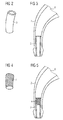
- FIG. 2 shows a hose or damper 3 as a vibration-influencing agent.
- the hose 3 is for example made of metal, is about as long as one third of the length of a carrying hook 2, and has an outer diameter of about the diameter of the sound channel 8 of the carrying hook second
- the weight and the shape of this can be changed, whereby the influence on natural vibrations of the carrying hook 2 by inserting the tube into the carrying hook 2 is variable.
- the choice of material also influences the weight.
- FIG. 3 shows the hose 3 FIG. 2 introduced into a carrying hook 2.
- the wall thickness and the length of the tube 3 are chosen so that the sound transmission in the sound channel 8 of the support hook 2 is not disturbed, and the sound-induced vibrations of the support hook effectively damped and / or shifted to lower, no longer audible frequencies become. It is sufficient if only a part of the sound channel 8 is lined with the tube 3.
- the tube 3 fits snugly in the sound channel 8, but can be removed, for example, if necessary by a hearing care professional and replaced by another tube 3.
- the suitable and effective vibration-influencing tube 3 can be easily selected.
- FIG. 4 shows an acoustic damping element 4, for example made of a fine plastic fabric, in the hose 3 from FIG. 3 is insertable.
- the frequency response of the sound transmission in the sound channel 8 can be changed if necessary.
- FIG. 5 is the acoustic damping element 4 after FIG. 4 along with the hose 3 after FIG. 2 in the sound channel 8 of the carrying hook 2 introduced. This fits snugly and unverurgingbar in the tube. 3
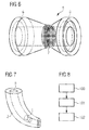
- FIG. 6 shows a further embodiment of the inventive device 5 in the form of a tube with two attached at both ends vibration damping weights 6 made of metal and an acoustic damping element 7.
- the Dampfungselement 7 includes, for example, a fine, gauzy plastic fabric. This combination is also known as a carrying hook damper.
- the vibration damping weights 6 may preferably be arranged symmetrically.
- FIG. 7 is the means 5 off FIG. 6 shown introduced into the sound channel 8 of a carrying hook 2.
- the means 5 is preferably arranged in the vicinity of the sound outlet end of the carrying hook 2.
- FIG. 8 indicates the course of the process according to the invention.
- step 100 a wearing hook 2 is provided.
- step 101 a means 3, 5 suitable for the carrying hook 2 is selected.
- step 102 the means 3, 5 are introduced into the sound channel 8 of the carrying hook 2.
Landscapes
- Health & Medical Sciences (AREA)
- General Health & Medical Sciences (AREA)
- Neurosurgery (AREA)
- Otolaryngology (AREA)
- Physics & Mathematics (AREA)
- Engineering & Computer Science (AREA)
- Acoustics & Sound (AREA)
- Signal Processing (AREA)
- Headphones And Earphones (AREA)
- Soundproofing, Sound Blocking, And Sound Damping (AREA)
- Vibration Prevention Devices (AREA)
- Details Of Audible-Bandwidth Transducers (AREA)
Abstract
Description
- Die Erfindung betrifft einen im Patentanspruch 1 angegebenes Tragehaken für ein Hörgerät und ein im Patentanspruch 10 angegebenes Verfahren zur Beeinflussung von Schwingungen eines Tragehakens.
- In der Regel sind Hörgeräte mit Hinter-dem-Ohr-Teil mit einem Tragehaken ausgerüstet, damit das Hinter-dem-Ohr-Teil bequem und sicher hinter dem Ohr des Hörgeräteträgers sitzt. Neben dieser Tragefunktion leitet der Tragehaken in seinem Inneren, im sogenannten Schallkanal, die in einem Hörer des Hinter-dem-Ohr-Teils gebildeten akustischen Signals zu einem mit dem Tragehaken verbundenen Schallschlauch. Dieser ist mit einem Ohrpassstück verbunden.
- Durch die Anregung mit Schallwellen eines ausgesendeten akustischen Signals vibriert aber der Tragehaken bzw. gerät im hörbaren Frequenzbereich in unerwünschte, störende Schwingungen. Diese durch Resonanz verursachten Schwingungen werden von einem Mikrophon im Hörgerät empfangen und von einer Verstärkerschaltung des Hörgeräts verstärkt. Dies führt insbesondere bei hohen Verstärkungen zu unerwünschten Schall-Kopplungen, die das akustische Nutzsignal störend überlagern.
- Zur Vermeidung von Schwingungen und störenden Kopplungen kann der Tragehaken steif ausgeführt werden. Steife Kunststoff-Tragehaken können aber leicht brechen und sind bezüglich ihrer metallenen Anschlusstücke in der Handhabung problematisch.
- In der Gebrauchsmusterschrift
DE 298 19415 U1 der Anmelderin werden verschiedene, verbesserte steife Tragehaken-Konstruktionen, beispielsweise mit einem Kunststoff-Metall-Verbund, beschrieben. - Es ist Aufgabe der Erfindung einen weiteren, einfach aufgebauten Tragehaken anzugeben, der keine störenden Schall-Kopplungen infolge von Schwingungen verursacht.
- Gemäß der Erfindung wird die gestellte Aufgabe mit der Anordnung gemäß dem unabhängigen Patentanspruch 1 durch die darin aufgeführten Merkmale gelöst, indem im Schallkanal eines Tragehakens für Hörgeräte mindesten ein schwingungsbeeinflussendes Mittel angeordnet ist.
- Dies bringt den Vorteil, dass Schwingungen des Tragehakens derart veränderbar sind, dass diese vom Hörgerät nicht mehr für einen Hörgeräteträger störend verstärkt werden können. Dadurch können Hörgeräte mehr Verstärkungsreserve aufweisen.
- Die Schwingungen sind unabhängig von der Materialeigenschaft und der Form des Tragehakens beeinflussbar.
- Fertigungstoleranzen des Traghakens wirken sich nicht mehr auf das Schwingungsverhalten des Tragehakens aus.
- In weiteren Ausführungsformen sind die Amplitude und die Frequenz der Schwingungen des Tragehakens durch die räumliche Lage des Mittels im Schallkanal und/oder durch die Form des Mittels und/oder durch das Gewicht des Mittels beeinflussbar.
- Dadurch gibt es große konstruktive Spielräume und unterschiedliche Möglichkeiten für eine Beeinflussung der Schwingungen des Tragehakens.
- Die Amplitude der Schwingungen kann verkleinerbar und/oder die Frequenz der Schwingungen kann erniedrigbar sein.
- Vorteilhaft daran ist, dass die Schwingungen zu unhörbar tiefen Frequenzen verschoben und/oder soweit gedämpft werden, dass sie nicht mehr hörbar verstärkt werden können.
- In einer weiteren Ausführungsform umfasst das Mittel einen im Schallkanal des Hörgerätehakens angeordneten metallenen Schlauch, der in Wirkverbindung mit dem Tragehaken steht.
- Dadurch kann entsprechend der Lage und Länge des Schlauchs Amplitude und Frequenz der Schwingung des Tragehakens einfach beeinflusst werden.
- In einer anderen Ausführungsform umfasst das Mittel ein oder mehrere Vibrationsdämpfungsgewichte.
- Dadurch kann die schwingungsbeeinflussende Wirkung des Mittels einfach gesteuert bzw. eingestellt werden.
- Im Inneren des Mittels kann ein akustisches Dämpfungselement angeordnet werden. Dieses beeinflusst die Ausbreitungseigenschaften der Schallwellen im Schallkanal.
- Dies hat den Vorteil, dass damit das Schallfrequenzspektrum einfach anpassbar ist.
- Der Tragehaken kann mit einem Hinter-dem-Ohr-Teil des Hörgeräts verbunden sein.
- Des Weiteren gibt die Erfindung ein Verfahren gemäß dem unabhängigen Patentanspruch 10 an, bei dem zur Dämpfung und Frequenzverschiebung schallinduzierter Schwingungen eines Tragehakens ein die Schwingungen beeinflussendes Mittel in den Schallkanal des Tragehakens geschoben wird.
- Weitere Besonderheiten der Erfindung werden aus den nachfolgenden Erläuterungen mehrerer Ausführungsbeispiele anhand von schematischen Zeichnungen ersichtlich.
- Es zeigen:
- Figur 1
- ein Hinter-dem-Ohr-Teil mit Tragehaken,
- Figur 2
- einen Schlauch,
- Figur 3
- einen Tragehaken mit Schlauch,
- Figur 4
- ein akustisches Dämpfungselement,
- Figur 5
- einen Tragehaken mit Schlauch und akustischem Dämp- fungselement,
- Figur 6
- einen Tragehakendämpfer,
- Figur 7
- einen Tragehaken mit Tragehakendämpfer, und
- Figur 8
- ein Ablaufdiagramm.
-
Figur 1 zeigt ein Hinter-dem-Ohr-Teil 1 eines Hörgeräts. Am oberen Ende des Hinter-dem-Ohr-Teil 1 ist ein erfindungsgemäßer Tragehaken 2 mit einem nicht sichtbaren schwingungsbeeinflussenden Mittel 3, 5 befestigt. Mit einem Mikrophon des Hinter-dem-Ohr-Teils 1 werden akustische Signale aufgenommen und als elektrische Signale einer Verstärkerschaltung zugeführt. Nach der Verarbeitung und Verstärkung der elektrischen Signale erfolgt in einem Hörer die Rückumwandlung in akustische Signale und die Weiterleitung über einen Schallkanal des Tragehakens 2. - Das vom Tragehaken 2 gebildete Gehäuseende des Hörgeräts weist an seinem Ende eine kegelstumpfförmige Verdickung auf, über die einen nicht dargestellter Schallschlauch geschoben werden kann, der den Schallkanal zum Gehörgang des Hörgeräteträgers weiterführt.
- Des Weiteren sind eine Schalterabdeckung, unter der sich ein Folientaster und eine Programmierbuchse befinden, und ein Lautstärkeregler sichtbar.
-
Figur 2 zeigt einen Schlauch bzw. Dämpfer 3 als schwingungsbeeinflussendes Mittel. Der Schlauch 3 besteht beispielsweise aus Metall, ist etwa so lang wie ein Drittel der Länge eines Tragehakens 2, und hat einen Außendurchmesser von ungefähr dem Durchmesser des Schallkanals 8 des Tragehakens 2. - Durch Veränderung der Länge und der Wandstärke des Schlauchs 3 können das Gewicht und die Form dieses verändert werden, wodurch der Einfluss auf Eigenschwingungen des Tragehakens 2 durch Einführen des Schlauchs in den Tragehaken 2 veränderbar ist. Auch die Wahl des Materials beeinflusst das Gewicht.
-
Figur 3 zeigt den Schlauch 3 ausFigur 2 eingeführt in einen Tragehaken 2. Die Wandstärke und die Länge des Schlauchs 3 sind so gewählt, dass die Schallübertragung im Schallkanal 8 des Tragehakens 2 nicht gestört wird, und die schallinduzierten Schwingungen des Tragehakens wirksam gedämpft und/oder zu niedrigeren, nicht mehr hörbaren Frequenzen verschoben werden. Es ist ausreichend, wenn nur ein Teil des Schallkanals 8 mit dem Schlauch 3 ausgekleidet ist. - Der Schlauch 3 sitzt passgenau im Schallkanal 8, kann aber zum Beispiel bei Bedarf von einem Hörgerätakustiker entfernt und durch einen anderen Schlauch 3 ersetzt werden.
- Durch Einführen des Schlauchs 3 in den Tragehaken 2 nach dessen Herstellung kann entsprechend der Form und des Materials des Tragehakens 2 einfach der geeignete und wirksame schwingungsbeeinflussende Schlauch 3 ausgewählt werden.
-
Figur 4 zeigt ein akustisches Dämpfungselement 4, beispielsweise aus einem feinen Kunststoffgewebe, das in den Schlauch 3 ausFigur 3 einführbar ist. Durch eine unterschiedliche Ausbildung des Kunststoffgewebes kann der Frequenzgang der Schallübertragung im Schallkanal 8 bei Bedarf verändert werden. - In
Figur 5 ist das akustische Dämpfungselement 4 nachFigur 4 zusammen mit dem Schlauch 3 nachFigur 2 in den Schallkanal 8 des Tragehakens 2 eingeführt. Dieses sitzt passgenau und unverrutschbar im Schlauch 3. -
Figur 6 zeigt eine weitere Ausführungsform des erfindungsgemäßen Mittels 5 in Form eines Rohres mit zwei an den beiden Enden aufgesetzten Vibrationsdämpfungsgewichten 6 aus Metall und einem akustischen Dämpfungselement 7. Das Dampfungselement 7 umfasst beispielsweise ein feines, gazeartiges Kunststoffgewebe. Diese Kombination wird auch als Tragehakendämpfer bezeichnet. Die Vibrationsdampfungsgewichte 6 können bevorzugt symmetrisch angeordnet sein. - In
Figur 7 ist das Mittel 5 ausFigur 6 in den Schallkanal 8 eines Tragehakens 2 eingeführt dargestellt. Für eine optimale Wirksamkeit wird das Mittel 5 bevorzugt in der Nähe des Schallaustrittendes des Tragehakens 2 angeordnet. -
Figur 8 gibt den Ablauf des erfindungsgemäßen Verfahrens wieder. In Schritt 100 wird ein Tragehaken 2 bereitgestellt. Im nachfolgenden Schritt 101 wird ein zum Traghaken 2 passendes Mittel 3, 5 ausgewählt. Im abschließenden Schritt 102 wird das Mittel 3, 5 in den Schallkanal 8 des Tragehakens 2 eingeführt.
Claims (10)
- Tragehaken (2) für Hörgeräte,
dadurch gekennzeichnet,
dass mindesten ein im Schallkanal (6) des Tragehakens (2) angeordnetes Mittel (3, 5) derart ausgestaltet ist, dass Schwingungen des Tragehakens (2) beeinflussbar sind. - Tragehaken (2) nach Anspruch 1,
dadurch gekennzeichnet,
dass Amplitude und Frequenz der Schwingungen des Tragehakens (2) durch die räumliche Lage des Mittels (3, 5) im Schallkanal beeinflussbar sind. - Tragehaken (2) nach Anspruch 1 oder 2,
dadurch gekennzeichnet,
dass Amplitude und Frequenz der Schwingungen des Tragehakens (2) durch die Form des Mittels (3, 5) beeinflussbar sind. - Tragehaken (2) nach einem der Ansprüche 1 bis 3,
dadurch gekennzeichnet,
dass Amplitude und Frequenz der Schwingungen des Tragehakens (2) durch das Gewicht des Mittels (3, 5) beeinflussbar sind. - Tragehaken (2) nach einem der vorigen Ansprüche,
dadurch gekennzeichnet,
dass die Amplitude der Schwingungen verkleinerbar und/oder die Frequenz der Schwingungen erniedrigbar ist. - Tragehaken (2) nach einem der vorigen Ansprüche,
dadurch gekennzeichnet,
dass das Mittel (3, 5) einen im Schallkanal (8) des Tragehakens (2) angeordneten metallischen Schlauch (3) umfasst, der in Wirkverbindung mit dem Tragehaken (2) steht. - Tragehaken (2) nach einem der vorigen Ansprüche,
dadurch gekennzeichnet,
dass das Mittel (5) ein oder mehrere Vibrationsdämpfungsgewichte (6) umfasst. - Tragehaken (2) nach einem der vorigen Ansprüche,
dadurch gekennzeichnet,
dass ein im Inneren des Mittels (3, 5) angeordnetes akustisches Dämpfungselement (4, 7) derart ausgebildet ist, dass die Ausbreitungseigenschaften der Schallwellen im Schallkanal (8) beeinflussbar sind. - Hörgerät mit einem Tragehaken (2) nach einem der vorigen Ansprüche,
dadurch gekennzeichnet,
dass der Tragehaken (2) mit einem Hinter-dem-Ohr-Teil (1) des Hörgeräts lösbar verbindbar ist. - Verfahren zur Dämpfung und Frequenzverschiebung schallinduzierter Schwingungen eines Tragehakens (2) eines Hörgeräts,
dadurch gekennzeichnet,
dass mindestens ein die Schwingungen beeinflussendes Mittel (3, 5) im Schallkanal (8) des Tragehakens (2) angeordnet wird.
Applications Claiming Priority (1)
| Application Number | Priority Date | Filing Date | Title |
|---|---|---|---|
| DE102007033289A DE102007033289A1 (de) | 2007-07-17 | 2007-07-17 | Anordnung mit Tragehaken für Hörgeräte und dazugehöriges Verfahren |
Publications (2)
| Publication Number | Publication Date |
|---|---|
| EP2018077A1 true EP2018077A1 (de) | 2009-01-21 |
| EP2018077B1 EP2018077B1 (de) | 2011-09-07 |
Family
ID=39790907
Family Applications (1)
| Application Number | Title | Priority Date | Filing Date |
|---|---|---|---|
| EP08104434A Not-in-force EP2018077B1 (de) | 2007-07-17 | 2008-06-17 | Tragehaken für Hörgerät mit schwingungsdämpfendem Mittel im Schallkanal |
Country Status (5)
| Country | Link |
|---|---|
| US (1) | US20090022349A1 (de) |
| EP (1) | EP2018077B1 (de) |
| AT (1) | ATE524023T1 (de) |
| DE (1) | DE102007033289A1 (de) |
| DK (1) | DK2018077T3 (de) |
Families Citing this family (1)
| Publication number | Priority date | Publication date | Assignee | Title |
|---|---|---|---|---|
| DE102009052574A1 (de) * | 2009-11-10 | 2011-05-12 | Siemens Medical Instruments Pte. Ltd. | Hörgerät mit Simulation eines Hörverlusts und Verfahren zur Simulation eines Hörverlusts |
Citations (5)
| Publication number | Priority date | Publication date | Assignee | Title |
|---|---|---|---|---|
| GB2039191A (en) | 1978-12-15 | 1980-07-30 | Danavox As | Hookshaped part of a behind-the ear hearing aid |
| US4677675A (en) * | 1985-09-17 | 1987-06-30 | Killion Mead C | Response-modifying acoustic couplers for hearing aids |
| DE29819415U1 (de) * | 1998-10-30 | 1999-01-28 | Siemens Audiologische Technik Gmbh, 91058 Erlangen | Tragehaken für hinter dem Ohr tragbare Hörhilfegeräte |
| US20050249369A1 (en) * | 2004-05-05 | 2005-11-10 | Phonak Ag | Flexible frequency response shaping |
| WO2006125434A1 (en) | 2005-05-25 | 2006-11-30 | Widex A/S | A hook for a hearing aid |
Family Cites Families (4)
| Publication number | Priority date | Publication date | Assignee | Title |
|---|---|---|---|---|
| US4291203A (en) * | 1979-09-11 | 1981-09-22 | Gaspare Bellafiore | Hearing aid device |
| DK148230C (da) * | 1982-11-05 | 1985-09-23 | Danavox As | Bag-oeret-hoereapparat med en krogformet lyddel |
| NL8400925A (nl) * | 1984-03-23 | 1985-10-16 | Philips Nv | Hoorapparaat, in het bijzonder achter-het-oor hoorapparaat. |
| DE102005036849A1 (de) * | 2005-08-04 | 2007-02-22 | Siemens Audiologische Technik Gmbh | Hörerschlauch mit Dämpfungselement und entsprechende Hörvorrichtung |
-
2007
- 2007-07-17 DE DE102007033289A patent/DE102007033289A1/de not_active Ceased
-
2008
- 2008-06-17 AT AT08104434T patent/ATE524023T1/de active
- 2008-06-17 DK DK08104434.9T patent/DK2018077T3/da active
- 2008-06-17 EP EP08104434A patent/EP2018077B1/de not_active Not-in-force
- 2008-07-17 US US12/174,908 patent/US20090022349A1/en not_active Abandoned
Patent Citations (5)
| Publication number | Priority date | Publication date | Assignee | Title |
|---|---|---|---|---|
| GB2039191A (en) | 1978-12-15 | 1980-07-30 | Danavox As | Hookshaped part of a behind-the ear hearing aid |
| US4677675A (en) * | 1985-09-17 | 1987-06-30 | Killion Mead C | Response-modifying acoustic couplers for hearing aids |
| DE29819415U1 (de) * | 1998-10-30 | 1999-01-28 | Siemens Audiologische Technik Gmbh, 91058 Erlangen | Tragehaken für hinter dem Ohr tragbare Hörhilfegeräte |
| US20050249369A1 (en) * | 2004-05-05 | 2005-11-10 | Phonak Ag | Flexible frequency response shaping |
| WO2006125434A1 (en) | 2005-05-25 | 2006-11-30 | Widex A/S | A hook for a hearing aid |
Also Published As
| Publication number | Publication date |
|---|---|
| DE102007033289A1 (de) | 2009-01-22 |
| US20090022349A1 (en) | 2009-01-22 |
| DK2018077T3 (da) | 2012-01-09 |
| ATE524023T1 (de) | 2011-09-15 |
| EP2018077B1 (de) | 2011-09-07 |
Similar Documents
| Publication | Publication Date | Title |
|---|---|---|
| DE102008052681B3 (de) | Ohrstück mit Stegen | |
| DE102006024411B4 (de) | Verfahren zum Erzeugen eines Schallsignals oder zum Übertragen von Energie in einem Gehörgang und entsprechende Hörvorrichtung | |
| DE102007031872B4 (de) | Hörgerät | |
| EP2229010B1 (de) | Hörgerät und Verfahren zur Störschallkompensation bei einem Hörgerät | |
| EP2023665B1 (de) | Hörereinrichtung mit beeinflussbarer Schallaustrittsrichtung | |
| EP2226795B1 (de) | Hörvorrichtung und Verfahren zum Reduzieren eines Störgeräuschs für eine Hörvorrichtung | |
| EP2509340A1 (de) | Gehörgangseinsatz mit einem Filterelement | |
| DE102009010892A1 (de) | Vorrichtung und Verfahren zur Reduzierung von Trittschallwirkungen bei Hörvorrichtungen mit aktiver Okklusionsreduktion | |
| DE102005036849A1 (de) | Hörerschlauch mit Dämpfungselement und entsprechende Hörvorrichtung | |
| EP2007172A1 (de) | Schallausgangsröhrchen mit 2-Komponenten-Aufbau | |
| DE69811657T2 (de) | Lautsprechersystem | |
| DE102018213834B3 (de) | Vorrichtung und verfahren zur modifizierung eines lautsprechersignals zur vermeidung einer membranüberauslenkung | |
| DE102005012976B3 (de) | Hörvorrichtung und Verfahren zur Windgeräuschunterdrückung | |
| EP2360949A2 (de) | Hörerschlauch mit Zugentlastung sowie Hörhilfe | |
| EP2018077B1 (de) | Tragehaken für Hörgerät mit schwingungsdämpfendem Mittel im Schallkanal | |
| EP3643077B1 (de) | In-ohr hörer | |
| EP1909533A2 (de) | Schallleiter und Hörvorrichtung | |
| EP1718112A1 (de) | Hörgerät mit Ohrkanalmikrofon | |
| DE102006035105B4 (de) | Hörgeräte für Musiker | |
| EP2001264B1 (de) | Tragehaken mit Metallabschnitt für ein Hörgerät | |
| EP2373065B1 (de) | Hörvorrichtung und Verfahren zum Erzeugen einer omnidirektionalen Richtcharakteristik | |
| DE202007018889U1 (de) | Hörgerät | |
| EP3334191A1 (de) | Gehäuse für ein hörgerät | |
| DE102008021357A1 (de) | Gehörschutz | |
| CH719171B1 (de) | Horn und Hornlautsprecher. |
Legal Events
| Date | Code | Title | Description |
|---|---|---|---|
| PUAI | Public reference made under article 153(3) epc to a published international application that has entered the european phase |
Free format text: ORIGINAL CODE: 0009012 |
|
| 17P | Request for examination filed |
Effective date: 20081113 |
|
| AK | Designated contracting states |
Kind code of ref document: A1 Designated state(s): AT BE BG CH CY CZ DE DK EE ES FI FR GB GR HR HU IE IS IT LI LT LU LV MC MT NL NO PL PT RO SE SI SK TR |
|
| AX | Request for extension of the european patent |
Extension state: AL BA MK RS |
|
| AKX | Designation fees paid |
Designated state(s): AT BE BG CH CY CZ DE DK EE ES FI FR GB GR HR HU IE IS IT LI LT LU LV MC MT NL NO PL PT RO SE SI SK TR |
|
| GRAP | Despatch of communication of intention to grant a patent |
Free format text: ORIGINAL CODE: EPIDOSNIGR1 |
|
| GRAS | Grant fee paid |
Free format text: ORIGINAL CODE: EPIDOSNIGR3 |
|
| GRAA | (expected) grant |
Free format text: ORIGINAL CODE: 0009210 |
|
| REG | Reference to a national code |
Ref country code: GB Ref legal event code: FG4D Free format text: NOT ENGLISH |
|
| REG | Reference to a national code |
Ref country code: CH Ref legal event code: NV Representative=s name: SIEMENS SCHWEIZ AG Ref country code: CH Ref legal event code: EP |
|
| REG | Reference to a national code |
Ref country code: IE Ref legal event code: FG4D Free format text: LANGUAGE OF EP DOCUMENT: GERMAN |
|
| REG | Reference to a national code |
Ref country code: DE Ref legal event code: R096 Ref document number: 502008004755 Country of ref document: DE Effective date: 20111103 |
|
| REG | Reference to a national code |
Ref country code: DK Ref legal event code: T3 |
|
| REG | Reference to a national code |
Ref country code: NL Ref legal event code: VDEP Effective date: 20110907 |
|
| PG25 | Lapsed in a contracting state [announced via postgrant information from national office to epo] |
Ref country code: LT Free format text: LAPSE BECAUSE OF FAILURE TO SUBMIT A TRANSLATION OF THE DESCRIPTION OR TO PAY THE FEE WITHIN THE PRESCRIBED TIME-LIMIT Effective date: 20110907 Ref country code: FI Free format text: LAPSE BECAUSE OF FAILURE TO SUBMIT A TRANSLATION OF THE DESCRIPTION OR TO PAY THE FEE WITHIN THE PRESCRIBED TIME-LIMIT Effective date: 20110907 Ref country code: SE Free format text: LAPSE BECAUSE OF FAILURE TO SUBMIT A TRANSLATION OF THE DESCRIPTION OR TO PAY THE FEE WITHIN THE PRESCRIBED TIME-LIMIT Effective date: 20110907 Ref country code: NO Free format text: LAPSE BECAUSE OF FAILURE TO SUBMIT A TRANSLATION OF THE DESCRIPTION OR TO PAY THE FEE WITHIN THE PRESCRIBED TIME-LIMIT Effective date: 20111207 Ref country code: HR Free format text: LAPSE BECAUSE OF FAILURE TO SUBMIT A TRANSLATION OF THE DESCRIPTION OR TO PAY THE FEE WITHIN THE PRESCRIBED TIME-LIMIT Effective date: 20110907 |
|
| LTIE | Lt: invalidation of european patent or patent extension |
Effective date: 20110907 |
|
| PG25 | Lapsed in a contracting state [announced via postgrant information from national office to epo] |
Ref country code: LV Free format text: LAPSE BECAUSE OF FAILURE TO SUBMIT A TRANSLATION OF THE DESCRIPTION OR TO PAY THE FEE WITHIN THE PRESCRIBED TIME-LIMIT Effective date: 20110907 Ref country code: GR Free format text: LAPSE BECAUSE OF FAILURE TO SUBMIT A TRANSLATION OF THE DESCRIPTION OR TO PAY THE FEE WITHIN THE PRESCRIBED TIME-LIMIT Effective date: 20111208 Ref country code: CY Free format text: LAPSE BECAUSE OF FAILURE TO SUBMIT A TRANSLATION OF THE DESCRIPTION OR TO PAY THE FEE WITHIN THE PRESCRIBED TIME-LIMIT Effective date: 20110907 Ref country code: SI Free format text: LAPSE BECAUSE OF FAILURE TO SUBMIT A TRANSLATION OF THE DESCRIPTION OR TO PAY THE FEE WITHIN THE PRESCRIBED TIME-LIMIT Effective date: 20110907 |
|
| REG | Reference to a national code |
Ref country code: IE Ref legal event code: FD4D |
|
| PG25 | Lapsed in a contracting state [announced via postgrant information from national office to epo] |
Ref country code: SK Free format text: LAPSE BECAUSE OF FAILURE TO SUBMIT A TRANSLATION OF THE DESCRIPTION OR TO PAY THE FEE WITHIN THE PRESCRIBED TIME-LIMIT Effective date: 20110907 Ref country code: IS Free format text: LAPSE BECAUSE OF FAILURE TO SUBMIT A TRANSLATION OF THE DESCRIPTION OR TO PAY THE FEE WITHIN THE PRESCRIBED TIME-LIMIT Effective date: 20120107 Ref country code: IE Free format text: LAPSE BECAUSE OF FAILURE TO SUBMIT A TRANSLATION OF THE DESCRIPTION OR TO PAY THE FEE WITHIN THE PRESCRIBED TIME-LIMIT Effective date: 20110907 Ref country code: CZ Free format text: LAPSE BECAUSE OF FAILURE TO SUBMIT A TRANSLATION OF THE DESCRIPTION OR TO PAY THE FEE WITHIN THE PRESCRIBED TIME-LIMIT Effective date: 20110907 |
|
| PG25 | Lapsed in a contracting state [announced via postgrant information from national office to epo] |
Ref country code: PL Free format text: LAPSE BECAUSE OF FAILURE TO SUBMIT A TRANSLATION OF THE DESCRIPTION OR TO PAY THE FEE WITHIN THE PRESCRIBED TIME-LIMIT Effective date: 20110907 Ref country code: IT Free format text: LAPSE BECAUSE OF FAILURE TO SUBMIT A TRANSLATION OF THE DESCRIPTION OR TO PAY THE FEE WITHIN THE PRESCRIBED TIME-LIMIT Effective date: 20110907 Ref country code: EE Free format text: LAPSE BECAUSE OF FAILURE TO SUBMIT A TRANSLATION OF THE DESCRIPTION OR TO PAY THE FEE WITHIN THE PRESCRIBED TIME-LIMIT Effective date: 20110907 Ref country code: NL Free format text: LAPSE BECAUSE OF FAILURE TO SUBMIT A TRANSLATION OF THE DESCRIPTION OR TO PAY THE FEE WITHIN THE PRESCRIBED TIME-LIMIT Effective date: 20110907 Ref country code: RO Free format text: LAPSE BECAUSE OF FAILURE TO SUBMIT A TRANSLATION OF THE DESCRIPTION OR TO PAY THE FEE WITHIN THE PRESCRIBED TIME-LIMIT Effective date: 20110907 Ref country code: PT Free format text: LAPSE BECAUSE OF FAILURE TO SUBMIT A TRANSLATION OF THE DESCRIPTION OR TO PAY THE FEE WITHIN THE PRESCRIBED TIME-LIMIT Effective date: 20120109 |
|
| PLBE | No opposition filed within time limit |
Free format text: ORIGINAL CODE: 0009261 |
|
| STAA | Information on the status of an ep patent application or granted ep patent |
Free format text: STATUS: NO OPPOSITION FILED WITHIN TIME LIMIT |
|
| PGFP | Annual fee paid to national office [announced via postgrant information from national office to epo] |
Ref country code: DK Payment date: 20120620 Year of fee payment: 5 |
|
| 26N | No opposition filed |
Effective date: 20120611 |
|
| PGFP | Annual fee paid to national office [announced via postgrant information from national office to epo] |
Ref country code: GB Payment date: 20120618 Year of fee payment: 5 |
|
| REG | Reference to a national code |
Ref country code: DE Ref legal event code: R097 Ref document number: 502008004755 Country of ref document: DE Effective date: 20120611 |
|
| BERE | Be: lapsed |
Owner name: SIEMENS MEDICAL INSTRUMENTS PTE. LTD. Effective date: 20120630 |
|
| PGFP | Annual fee paid to national office [announced via postgrant information from national office to epo] |
Ref country code: FR Payment date: 20120711 Year of fee payment: 5 |
|
| PG25 | Lapsed in a contracting state [announced via postgrant information from national office to epo] |
Ref country code: MC Free format text: LAPSE BECAUSE OF NON-PAYMENT OF DUE FEES Effective date: 20120630 |
|
| REG | Reference to a national code |
Ref country code: CH Ref legal event code: PL |
|
| REG | Reference to a national code |
Ref country code: CH Ref legal event code: PL |
|
| REG | Reference to a national code |
Ref country code: DE Ref legal event code: R119 Ref document number: 502008004755 Country of ref document: DE Effective date: 20130101 |
|
| PG25 | Lapsed in a contracting state [announced via postgrant information from national office to epo] |
Ref country code: BE Free format text: LAPSE BECAUSE OF NON-PAYMENT OF DUE FEES Effective date: 20120630 Ref country code: CH Free format text: LAPSE BECAUSE OF NON-PAYMENT OF DUE FEES Effective date: 20120630 Ref country code: LI Free format text: LAPSE BECAUSE OF NON-PAYMENT OF DUE FEES Effective date: 20120630 Ref country code: DE Free format text: LAPSE BECAUSE OF NON-PAYMENT OF DUE FEES Effective date: 20130101 Ref country code: ES Free format text: LAPSE BECAUSE OF FAILURE TO SUBMIT A TRANSLATION OF THE DESCRIPTION OR TO PAY THE FEE WITHIN THE PRESCRIBED TIME-LIMIT Effective date: 20111218 |
|
| PG25 | Lapsed in a contracting state [announced via postgrant information from national office to epo] |
Ref country code: BG Free format text: LAPSE BECAUSE OF FAILURE TO SUBMIT A TRANSLATION OF THE DESCRIPTION OR TO PAY THE FEE WITHIN THE PRESCRIBED TIME-LIMIT Effective date: 20111207 |
|
| PG25 | Lapsed in a contracting state [announced via postgrant information from national office to epo] |
Ref country code: MT Free format text: LAPSE BECAUSE OF FAILURE TO SUBMIT A TRANSLATION OF THE DESCRIPTION OR TO PAY THE FEE WITHIN THE PRESCRIBED TIME-LIMIT Effective date: 20110907 |
|
| REG | Reference to a national code |
Ref country code: DK Ref legal event code: EBP Effective date: 20130630 |
|
| GBPC | Gb: european patent ceased through non-payment of renewal fee |
Effective date: 20130617 |
|
| REG | Reference to a national code |
Ref country code: FR Ref legal event code: ST Effective date: 20140228 |
|
| PG25 | Lapsed in a contracting state [announced via postgrant information from national office to epo] |
Ref country code: GB Free format text: LAPSE BECAUSE OF NON-PAYMENT OF DUE FEES Effective date: 20130617 Ref country code: TR Free format text: LAPSE BECAUSE OF FAILURE TO SUBMIT A TRANSLATION OF THE DESCRIPTION OR TO PAY THE FEE WITHIN THE PRESCRIBED TIME-LIMIT Effective date: 20110907 |
|
| PG25 | Lapsed in a contracting state [announced via postgrant information from national office to epo] |
Ref country code: FR Free format text: LAPSE BECAUSE OF NON-PAYMENT OF DUE FEES Effective date: 20130701 Ref country code: LU Free format text: LAPSE BECAUSE OF NON-PAYMENT OF DUE FEES Effective date: 20120617 |
|
| PG25 | Lapsed in a contracting state [announced via postgrant information from national office to epo] |
Ref country code: HU Free format text: LAPSE BECAUSE OF FAILURE TO SUBMIT A TRANSLATION OF THE DESCRIPTION OR TO PAY THE FEE WITHIN THE PRESCRIBED TIME-LIMIT Effective date: 20080617 |
|
| REG | Reference to a national code |
Ref country code: AT Ref legal event code: MM01 Ref document number: 524023 Country of ref document: AT Kind code of ref document: T Effective date: 20130617 |
|
| PG25 | Lapsed in a contracting state [announced via postgrant information from national office to epo] |
Ref country code: DK Free format text: LAPSE BECAUSE OF NON-PAYMENT OF DUE FEES Effective date: 20130630 |
|
| PG25 | Lapsed in a contracting state [announced via postgrant information from national office to epo] |
Ref country code: AT Free format text: LAPSE BECAUSE OF NON-PAYMENT OF DUE FEES Effective date: 20130617 |