EP2017659B1 - A fibre optic sensor and method for making - Google Patents
A fibre optic sensor and method for making Download PDFInfo
- Publication number
- EP2017659B1 EP2017659B1 EP08156110.2A EP08156110A EP2017659B1 EP 2017659 B1 EP2017659 B1 EP 2017659B1 EP 08156110 A EP08156110 A EP 08156110A EP 2017659 B1 EP2017659 B1 EP 2017659B1
- Authority
- EP
- European Patent Office
- Prior art keywords
- ceramic material
- fiber
- optical
- optical agents
- open pore
- Prior art date
- Legal status (The legal status is an assumption and is not a legal conclusion. Google has not performed a legal analysis and makes no representation as to the accuracy of the status listed.)
- Ceased
Links
- 239000000835 fiber Substances 0.000 title claims description 97
- 238000000034 method Methods 0.000 title claims description 15
- 229910010293 ceramic material Inorganic materials 0.000 claims description 73
- 230000003287 optical effect Effects 0.000 claims description 67
- 239000011148 porous material Substances 0.000 claims description 51
- 239000003795 chemical substances by application Substances 0.000 claims description 49
- VYPSYNLAJGMNEJ-UHFFFAOYSA-N Silicium dioxide Chemical compound O=[Si]=O VYPSYNLAJGMNEJ-UHFFFAOYSA-N 0.000 claims description 36
- KDLHZDBZIXYQEI-UHFFFAOYSA-N Palladium Chemical compound [Pd] KDLHZDBZIXYQEI-UHFFFAOYSA-N 0.000 claims description 24
- 239000000203 mixture Substances 0.000 claims description 17
- 239000000377 silicon dioxide Substances 0.000 claims description 17
- 239000012798 spherical particle Substances 0.000 claims description 16
- XOLBLPGZBRYERU-UHFFFAOYSA-N tin dioxide Chemical compound O=[Sn]=O XOLBLPGZBRYERU-UHFFFAOYSA-N 0.000 claims description 14
- GWEVSGVZZGPLCZ-UHFFFAOYSA-N Titan oxide Chemical compound O=[Ti]=O GWEVSGVZZGPLCZ-UHFFFAOYSA-N 0.000 claims description 12
- 238000005253 cladding Methods 0.000 claims description 12
- 230000008569 process Effects 0.000 claims description 12
- 229910052763 palladium Inorganic materials 0.000 claims description 11
- 238000007598 dipping method Methods 0.000 claims description 10
- 239000011248 coating agent Substances 0.000 claims description 9
- 238000000576 coating method Methods 0.000 claims description 9
- 229910052723 transition metal Inorganic materials 0.000 claims description 7
- 150000003624 transition metals Chemical class 0.000 claims description 7
- 229910044991 metal oxide Inorganic materials 0.000 claims description 5
- 150000004706 metal oxides Chemical class 0.000 claims description 5
- XHCLAFWTIXFWPH-UHFFFAOYSA-N [O-2].[O-2].[O-2].[O-2].[O-2].[V+5].[V+5] Chemical compound [O-2].[O-2].[O-2].[O-2].[O-2].[V+5].[V+5] XHCLAFWTIXFWPH-UHFFFAOYSA-N 0.000 claims description 4
- QGLKJKCYBOYXKC-UHFFFAOYSA-N nonaoxidotritungsten Chemical compound O=[W]1(=O)O[W](=O)(=O)O[W](=O)(=O)O1 QGLKJKCYBOYXKC-UHFFFAOYSA-N 0.000 claims description 4
- OGIDPMRJRNCKJF-UHFFFAOYSA-N titanium oxide Inorganic materials [Ti]=O OGIDPMRJRNCKJF-UHFFFAOYSA-N 0.000 claims description 4
- 229910001930 tungsten oxide Inorganic materials 0.000 claims description 4
- 229910001935 vanadium oxide Inorganic materials 0.000 claims description 4
- SIWVEOZUMHYXCS-UHFFFAOYSA-N oxo(oxoyttriooxy)yttrium Chemical compound O=[Y]O[Y]=O SIWVEOZUMHYXCS-UHFFFAOYSA-N 0.000 claims description 3
- 230000004044 response Effects 0.000 description 26
- 239000007789 gas Substances 0.000 description 20
- BDERNNFJNOPAEC-UHFFFAOYSA-N propan-1-ol Chemical compound CCCO BDERNNFJNOPAEC-UHFFFAOYSA-N 0.000 description 18
- 238000010438 heat treatment Methods 0.000 description 14
- 239000000243 solution Substances 0.000 description 13
- XQMTUIZTZJXUFM-UHFFFAOYSA-N tetraethoxy silicate Chemical compound CCOO[Si](OOCC)(OOCC)OOCC XQMTUIZTZJXUFM-UHFFFAOYSA-N 0.000 description 13
- 239000000126 substance Substances 0.000 description 12
- 239000000463 material Substances 0.000 description 11
- LFQSCWFLJHTTHZ-UHFFFAOYSA-N Ethanol Chemical compound CCO LFQSCWFLJHTTHZ-UHFFFAOYSA-N 0.000 description 9
- 229910002091 carbon monoxide Inorganic materials 0.000 description 9
- 238000010586 diagram Methods 0.000 description 8
- 229920000642 polymer Polymers 0.000 description 8
- 239000002245 particle Substances 0.000 description 7
- XLYOFNOQVPJJNP-UHFFFAOYSA-N water Substances O XLYOFNOQVPJJNP-UHFFFAOYSA-N 0.000 description 7
- QGZKDVFQNNGYKY-UHFFFAOYSA-N Ammonia Chemical compound N QGZKDVFQNNGYKY-UHFFFAOYSA-N 0.000 description 6
- 230000001680 brushing effect Effects 0.000 description 5
- 230000008859 change Effects 0.000 description 5
- 239000011521 glass Substances 0.000 description 5
- 238000005096 rolling process Methods 0.000 description 5
- 238000005507 spraying Methods 0.000 description 5
- 239000000853 adhesive Substances 0.000 description 4
- 230000001070 adhesive effect Effects 0.000 description 4
- 239000012790 adhesive layer Substances 0.000 description 4
- PNEYBMLMFCGWSK-UHFFFAOYSA-N aluminium oxide Inorganic materials [O-2].[O-2].[O-2].[Al+3].[Al+3] PNEYBMLMFCGWSK-UHFFFAOYSA-N 0.000 description 4
- 239000000919 ceramic Substances 0.000 description 4
- 238000005524 ceramic coating Methods 0.000 description 4
- UFHFLCQGNIYNRP-UHFFFAOYSA-N Hydrogen Chemical compound [H][H] UFHFLCQGNIYNRP-UHFFFAOYSA-N 0.000 description 3
- 229910021529 ammonia Inorganic materials 0.000 description 3
- 238000001035 drying Methods 0.000 description 3
- 229910052739 hydrogen Inorganic materials 0.000 description 3
- 239000001257 hydrogen Substances 0.000 description 3
- 238000005259 measurement Methods 0.000 description 3
- 229920000620 organic polymer Polymers 0.000 description 3
- 239000000758 substrate Substances 0.000 description 3
- UGFAIRIUMAVXCW-UHFFFAOYSA-N Carbon monoxide Chemical compound [O+]#[C-] UGFAIRIUMAVXCW-UHFFFAOYSA-N 0.000 description 2
- 238000007796 conventional method Methods 0.000 description 2
- 238000005336 cracking Methods 0.000 description 2
- 238000001514 detection method Methods 0.000 description 2
- 230000004048 modification Effects 0.000 description 2
- 238000012986 modification Methods 0.000 description 2
- 125000002524 organometallic group Chemical group 0.000 description 2
- BASFCYQUMIYNBI-UHFFFAOYSA-N platinum Chemical compound [Pt] BASFCYQUMIYNBI-UHFFFAOYSA-N 0.000 description 2
- 239000002243 precursor Substances 0.000 description 2
- -1 yittrium oxide Chemical compound 0.000 description 2
- 229910001252 Pd alloy Inorganic materials 0.000 description 1
- 229920003171 Poly (ethylene oxide) Polymers 0.000 description 1
- 239000004743 Polypropylene Substances 0.000 description 1
- KJTLSVCANCCWHF-UHFFFAOYSA-N Ruthenium Chemical compound [Ru] KJTLSVCANCCWHF-UHFFFAOYSA-N 0.000 description 1
- 238000005411 Van der Waals force Methods 0.000 description 1
- 238000010521 absorption reaction Methods 0.000 description 1
- 230000006978 adaptation Effects 0.000 description 1
- 239000012080 ambient air Substances 0.000 description 1
- 239000007864 aqueous solution Substances 0.000 description 1
- 238000006243 chemical reaction Methods 0.000 description 1
- 150000001875 compounds Chemical class 0.000 description 1
- 238000001704 evaporation Methods 0.000 description 1
- 239000005350 fused silica glass Substances 0.000 description 1
- 229920000126 latex Polymers 0.000 description 1
- 239000004816 latex Substances 0.000 description 1
- 239000011159 matrix material Substances 0.000 description 1
- 229910052751 metal Inorganic materials 0.000 description 1
- 239000002184 metal Substances 0.000 description 1
- 150000002739 metals Chemical class 0.000 description 1
- 239000004005 microsphere Substances 0.000 description 1
- 238000002156 mixing Methods 0.000 description 1
- 239000003607 modifier Substances 0.000 description 1
- 239000013307 optical fiber Substances 0.000 description 1
- 229910003445 palladium oxide Inorganic materials 0.000 description 1
- 229910052697 platinum Inorganic materials 0.000 description 1
- 229920000728 polyester Polymers 0.000 description 1
- 229920000098 polyolefin Polymers 0.000 description 1
- 229920001155 polypropylene Polymers 0.000 description 1
- 229920001451 polypropylene glycol Polymers 0.000 description 1
- 229910052703 rhodium Inorganic materials 0.000 description 1
- 239000010948 rhodium Substances 0.000 description 1
- MHOVAHRLVXNVSD-UHFFFAOYSA-N rhodium atom Chemical compound [Rh] MHOVAHRLVXNVSD-UHFFFAOYSA-N 0.000 description 1
- 229910052707 ruthenium Inorganic materials 0.000 description 1
- 229910052594 sapphire Inorganic materials 0.000 description 1
- 239000010980 sapphire Substances 0.000 description 1
- 239000011540 sensing material Substances 0.000 description 1
- 230000035945 sensitivity Effects 0.000 description 1
- 238000012360 testing method Methods 0.000 description 1
Images


Classifications
-
- G—PHYSICS
- G01—MEASURING; TESTING
- G01N—INVESTIGATING OR ANALYSING MATERIALS BY DETERMINING THEIR CHEMICAL OR PHYSICAL PROPERTIES
- G01N21/00—Investigating or analysing materials by the use of optical means, i.e. using sub-millimetre waves, infrared, visible or ultraviolet light
- G01N21/75—Systems in which material is subjected to a chemical reaction, the progress or the result of the reaction being investigated
- G01N21/77—Systems in which material is subjected to a chemical reaction, the progress or the result of the reaction being investigated by observing the effect on a chemical indicator
- G01N21/7703—Systems in which material is subjected to a chemical reaction, the progress or the result of the reaction being investigated by observing the effect on a chemical indicator using reagent-clad optical fibres or optical waveguides
-
- C—CHEMISTRY; METALLURGY
- C03—GLASS; MINERAL OR SLAG WOOL
- C03C—CHEMICAL COMPOSITION OF GLASSES, GLAZES OR VITREOUS ENAMELS; SURFACE TREATMENT OF GLASS; SURFACE TREATMENT OF FIBRES OR FILAMENTS MADE FROM GLASS, MINERALS OR SLAGS; JOINING GLASS TO GLASS OR OTHER MATERIALS
- C03C25/00—Surface treatment of fibres or filaments made from glass, minerals or slags
- C03C25/10—Coating
- C03C25/104—Coating to obtain optical fibres
- C03C25/106—Single coatings
- C03C25/1061—Inorganic coatings
-
- C—CHEMISTRY; METALLURGY
- C03—GLASS; MINERAL OR SLAG WOOL
- C03C—CHEMICAL COMPOSITION OF GLASSES, GLAZES OR VITREOUS ENAMELS; SURFACE TREATMENT OF GLASS; SURFACE TREATMENT OF FIBRES OR FILAMENTS MADE FROM GLASS, MINERALS OR SLAGS; JOINING GLASS TO GLASS OR OTHER MATERIALS
- C03C25/00—Surface treatment of fibres or filaments made from glass, minerals or slags
- C03C25/10—Coating
- C03C25/12—General methods of coating; Devices therefor
-
- G—PHYSICS
- G02—OPTICS
- G02B—OPTICAL ELEMENTS, SYSTEMS OR APPARATUS
- G02B6/00—Light guides; Structural details of arrangements comprising light guides and other optical elements, e.g. couplings
- G02B6/02—Optical fibres with cladding with or without a coating
- G02B6/02057—Optical fibres with cladding with or without a coating comprising gratings
- G02B6/02076—Refractive index modulation gratings, e.g. Bragg gratings
- G02B6/0208—Refractive index modulation gratings, e.g. Bragg gratings characterised by their structure, wavelength response
- G02B6/021—Refractive index modulation gratings, e.g. Bragg gratings characterised by their structure, wavelength response characterised by the core or cladding or coating, e.g. materials, radial refractive index profiles, cladding shape
- G02B6/02104—Refractive index modulation gratings, e.g. Bragg gratings characterised by their structure, wavelength response characterised by the core or cladding or coating, e.g. materials, radial refractive index profiles, cladding shape characterised by the coating external to the cladding, e.g. coating influences grating properties
-
- G—PHYSICS
- G01—MEASURING; TESTING
- G01N—INVESTIGATING OR ANALYSING MATERIALS BY DETERMINING THEIR CHEMICAL OR PHYSICAL PROPERTIES
- G01N21/00—Investigating or analysing materials by the use of optical means, i.e. using sub-millimetre waves, infrared, visible or ultraviolet light
- G01N21/75—Systems in which material is subjected to a chemical reaction, the progress or the result of the reaction being investigated
- G01N21/77—Systems in which material is subjected to a chemical reaction, the progress or the result of the reaction being investigated by observing the effect on a chemical indicator
- G01N21/7703—Systems in which material is subjected to a chemical reaction, the progress or the result of the reaction being investigated by observing the effect on a chemical indicator using reagent-clad optical fibres or optical waveguides
- G01N2021/7706—Reagent provision
- G01N2021/7726—Porous glass
Definitions
- This invention relates generally to a method for making a fiber optic sensor and more particularly, for a fiber optic sensor for harsh environments.
- Fiber optic sensors may be used to monitor dynamic chemical and physical processes that are associated with changes in an environment.
- a typical fiber optic sensor positions a sensor material, with the assistance of one or more types of support, to interact with the substance or environment that is being monitored, measured and/or detected.
- a chemical fiber optic sensor contains an optical agent that identifies optical index changes based upon unique chemical environments. To function properly, the optical agent must be in an optically clear support structure that holds the optical agent and permits the optical agent to interact with the environment or substance being monitored, measured or detected.
- U.S. Patent No. 5,496,997 to Pope discloses an optical fiber where the distal end of the fiber is coupled to amorphous silica microspheres by an adhesive material.
- the sensor can fail in harsh environments, as the adhesive layer may break down at high temperatures or in the harsh environments.
- fiber optic sensor comprising a fiber having a cladding and a modified surface integral with the fiber, wherein the fiber surface is modified by applying ceramic material, said modified surface comprising an open pore network and optical agents dispersed within the open pores of the open pore network, wherein the modified surface is intimately bonded to the fibre surface and wherein the optical agents comprise a Group 8-10 transition metal or a metal oxide selected from the group consisting of tin dioxide, yttrium oxide, vanadium oxide, titanium oxide and tungsten oxide and said modified surface is on the cladding.
- a process for making a fiber optic sensor comprising applying ceramic material to a fiber having a cladding and forming an open pore network structure, dispersing optical agents within the pores of the open pore network and integrating the ceramic material with the fiber, wherein the step of applying ceramic material consists of applying ceramic material or a mixture comprising ceramic material and optical agents to the cladding such that the modified surface is intimately bonded to the fibre surface; and wherein said optical agents comprise a Group 8-10 transition metal or a metal oxide selected from the group consisting of tin dioxide, yttrium oxide, vanadium oxide, titanium oxide and tungsten oxide.
- the various embodiments provide fiber optic sensors that can withstand high temperatures and harsh environments.
- a fiber optic sensor comprises a fiber having a modified surface integral with the fiber, said modified surface comprising an open pore network and optical agents disposed within the open pores of the open pore network.
- a fiber optic sensor may be used to measure physical, electrical and chemical parameters.
- the fiber optic sensor is a chemical fiber optic sensor.
- a fiber comprises a fiber core and a fiber cladding.
- the fiber cladding at least partly surrounds the fiber core, which forms a waveguide that extends longitudinally along an axis and includes parts having variations in refractive index (or optical thickness) to form an optical diffraction grating.
- the fiber core is transparent and may comprise sapphire, a porous sol-gel glass or a fused silica material.
- the fiber cladding may be transparent and may be made of the same material as the core, but with a low refractive index.
- the fiber cladding comprises glass or silica.
- the modified surface is on the fiber cladding of the fiber.
- the modification to the fiber comprises applying a ceramic material to the surface of the fiber in any conventional manner. As the ceramic material solidifies, it forms a porous and optically clear support structure, which is a three-dimensional matrix or lattice type structure with a plurality of interconnecting pores that extend completely throughout the support structure and create an open pore network.
- the pore sizes may be any size suitable for allowing a sensing gas to pass through the support structure.
- the pore sizes are up to about 150 nm in diameter.
- the pores sizes are from about 1 nm to about 150 nm in diameter.
- the pore sizes may be controlled in a conventional manner by adjusting the time and temperature while the material is solidifying.
- the ceramic material is applied by spraying, brushing, rolling, pouring, dipping, immersing coating or applying a film to a surface of the fiber.
- a surface of the fiber is modified by coating the surface.
- a surface is modified by dipping the fiber.
- a surface is modified by forming a film on the surface.
- the ceramic material may be silica, alumina or titania.
- the alumina, titania and silica may be derived from an organo-metallic, such as a tetraethoxyorthosilicate.
- the ceramic material comprises silica.
- Optical agents are sensors that chemically sense unique chemical environments and measure the optical index of the fiber cladding.
- Optical agents may be any type of sensor that is known in the art.
- the optical agents may be metals or transition metals.
- the transition metal is any compound comprising Group 8-10 transition metals, such as ruthenium, rhodium, platinum and palladium.
- the optical agent is palladium.
- the optical agent may include a metal oxide.
- the metal oxide may include tin dioxide, yittrium oxide, vanadium oxide, titanium oxide and tungsten oxide.
- the optical agents are disposed within the open pores of the open pore network and are at least partially exposed to the ambient air.
- Optical agents are disposed into the open pores by dispersing the optical agents into the open pore network by any conventional method.
- the optical agents may be dispersed by spraying, brushing, rolling, pouring, dipping, immersing or coating the modified surface with the optical agents.
- the optical agents are dispersed within the pores of the open pore network by dipping the modified fiber optic into a solution comprising optical agents.
- the solution may be prepared by blending optical agents with water or alcohol.
- the ceramic material is integrated with the fiber by intimately bonding the ceramic material to a fiber surface without the need for adhesive materials or adhesive layers.
- the ceramic material infiltrates the surface of the fiber to form an integrated and modified surface on the fiber that effectively replaces the fiber surface with the new modified surface.
- the ceramic material may be integrated with the fiber by any means suitable for densifying and intimately bonding the ceramic material to a fiber surface.
- the densified ceramic material forms an open pore network within a dense structure that holds the optical agents in place and provides access to the environment or substance that is to be measured, monitored or detected. This open pore network holds and protects the optical agents in a support structure that is thermally, chemically and mechanically robust and stable.
- the ceramic material may be densified and bonded to the fiber by heat treatment, drying or irradiation. In another embodiment, the ceramic material is heat treated. Heat treatment may be made in any conventional manner. In one embodiment, the modified fiber is heated between about 300°C and about 600°C for up to about 4 hours. In one embodiment, the modified fiber is heated for about 1 to about 3 hours. Continued heating at higher temperatures or for longer times will eventually cause the open pore network to become fully dense having little or no porosity.
- a process for making a fiber optic sensor comprises applying ceramic material to a fiber to form an open pore network structure, dispersing optical agents within the pores of the open pore network and integrating the ceramic material with the fiber.
- the ceramic material may be silica, alumina or titania.
- the alumina, titania and silica may be derived from an organo-metallic, such as a tetraethoxyorthosilicate.
- the ceramic material comprises spherical particles having diameters in a range from about 20 nm to about 700 nm. The diameters are measured by a scanning electron microscope. In one embodiment, the spherical particles are monosized. In another embodiment, at least about 95% of the spherical particles are within about 10% of the mean diameter of the spherical particles.
- the ceramic material comprises spherical particles of silica.
- Spherical particles of silica may be made by adding a silica precursor, such as tetraethoxyorthosilicate, into a solution comprising alcohol and optionally, water from about 1 to about 50 percent by weight ammonia. The size of the particles is controlled by the relative concentrations of water, ammonia and alcohol.
- the alcohol is ethanol.
- the amount of alcohol is in the range of from about 10 to about 70 percent by weight based on the weight of the solution.
- the amount of ammonia is present from about 1 to about 50 percent by weight based on the weight of the solution.
- the amount of water is present from about 10 to about 70 percent by weight based on the weight of the solution.
- the amount of silica precursor is present from about 1 to about 10 percent by weight based on the weight of the solution.
- the ceramic material comprising spherical particles is applied by spraying, brushing, rolling, pouring, dipping, immersing coating or applying a film to a surface of the fiber.
- a surface of the fiber is modified by dipping the fiber into an aqueous solution of ceramic spherical particles. The spherical particles adhere to the surface of the fiber through van der Waals forces. As the water from the solution dries, capillary forces from the evaporating water film pull the spherical particles into a dense network of touching particles and open spaces forming open pores.
- the optical agents are dispersed within the open pores of the open pore network by any conventional method. As stated above, the optical agents may be dispersed by spraying, brushing, rolling, pouring, dipping, immersing or coating the modified surface with the optical agents. In one embodiment, the optical agent is dispersed within the open pore network by solution. The optical agents are added to a solution comprising water or alcohol and the fiber with the modified surface is dipped into the solution. Repeated steps of dispersing the optical agent into the open pore network may be used to increase the concentration of the optical agents on the fiber. The optical agents are situated within the open pores of the open pore network and are at least partially exposed to the environment or substance to be measured.
- the ceramic material is integrated with a fiber surface by any means suitable for densifying and intimately bonding the ceramic material to the fiber without the need for adhesive materials or adhesive layers.
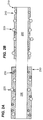
- Figure 1A is a diagram depicting a fiber 10 before heat treatment.
- the surface of the fiber 10 is modified by the application of a ceramic material 20 comprising ceramic spherical particles.
- the ceramic particles 20 adhere to the surface of the fiber 10 and form an open pore network of touching particles and open spaces 30.
- Optical agents 40 are dispersed within the open pores 30 of the open pore network.
- Figure 1B is a diagram depicting the fiber optic 10 after heat treatment.
- the ceramic spherical particles 20 densify and integrate with the fiber 10 to form an open pore network within a dense ceramic material 20.
- the optical agents 40 are supported and held in place by the open pore network in the ceramic material 20 and are exposed to the environment or substance to be measured.
- a process for making a fiber optic sensor comprises applying a ceramic material mixture comprising ceramic material and optical agents to a fiber, forming an open pore network structure within the ceramic material and integrating the ceramic material with the fiber.
- the ceramic material mixture comprises ceramic material and optical agents.
- the ceramic material mixture is prepared by adding optical agents to the ceramic material.
- the optical agents may be blended with the ceramic material in any conventional manner.
- the optical agents and ceramic material are blended together in solution.
- a solution of tetraethoxyorthosilicate, alcohol and optical agents is prepared.
- the ceramic material mixture is applied to a fiber surface in any conventional manner.
- the ceramic material is applied by spraying, brushing, rolling, pouring, dipping, immersing coating or applying a film to the surface.
- the ceramic material mixture is applied by coating the surface of the fiber.
- the ceramic material mixture is applied by dipping the fiber.
- a film comprising the ceramic material mixture is formed on the surface of the fiber.
- the open pore network may be formed by any suitable means for hardening ceramic material, such as drying or heat treating. As the ceramic material dries or is heated, the ceramic material begins to gel and cracks begin to form in the ceramic material. The cracks provide an open pore network within the dense ceramic material. The amount of cracking can be controlled by the rate of change of humidity and by the heat or drying rate.
- the ceramic material is integrated with the fiber optic by any means suitable for densifying and intimately bonding the ceramic material to the fiber without the need for adhesive materials or adhesive layers.
- the ceramic material mixture further comprises a polymer.
- the polymer may be any type of organic polymer that will decompose at elevated temperatures, such as during a heat treatment step.
- the organic polymer may be oxides of polyolefins, latex polymers, polyesters and polypropylenes.
- the organic polymer includes polyethylene oxide or polypropylene oxide. The polymer may be added to the ceramic material in an amount of from about 0.1 to about 10 percent by volume based on the ceramic material.
- the polymer aids in producing an open pore network within a dense ceramic material by causing cracks and voids to form in the ceramic coating.
- the ceramic material is heat treated in any conventional manner and the polymer will decompose during the heat treating step and leave voids in the coating, which will increase the open pores within the dense ceramic coating.
- the voids and cracks within the ceramic coating are large enough to allow gas to diffuse through the voids, but are small enough to not cause structural damage to the ceramic coating.
- the voids may be from about 10 ⁇ in diameter to about 100 ⁇ in diameter.
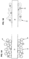
- Figure 2A is a diagram depicting a fiber 200 before heat treatment.
- a mixture of a ceramic material 210, optical agents 220 and a polymer 230 are applied to the surface of a fiber 200 and allowed to dry under a controlled humidity to induce cracking (not shown) in the dense ceramic material.
- Figure 2B is a diagram depicting a fiber 200 after heat treatment.
- the modified surface is heat treated and during heat treatment, the ceramic material 210 densifies and intimately bonds with the fiber optic 200.
- the polymer 230 decomposes leaving voids 240 in the ceramic material 210.
- the optical agents 220 are supported and held in place within the open pore network formed within the ceramic material 210 and are exposed to the environment or substance to be measured.
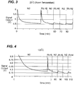
- a mixture of 89.5 percent by weight tetraethoxyorthosilicate, 10.5 percent by weight palladium and 40 percent by weight based on the weight of the tetraethoxyorthosilicate and palladium of 1-propanol was prepared.
- a film of the mixture of silica and palladium was applied to a glass substrate and heat treated at 400°C for 2 hours.
- the film thickness was about 100 ⁇ m.
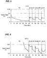
- Figures 3-8 show the H 2 response optical reflection curve between alternating 5% H 2 in N 2 gas at 25°C (room temperature), 120°C, 172°C, 355°C, 425°C and 525°C, respectively.
- the sensor measured H 2 sensing up to about 355°C.
- the relative response to the H 2 gas is summarized in Figure 9 .
- the relative response which is the quotient of the change of signal to the signal level.
- the values are evaluated by the average using the faster change signal. The results show that in the temperature range where the film is capable of sensing, sensitivity increases with increasing temperatures.
- Figure 10 is the response time over temperature.
- the response time values are evaluated by an average using the faster change signal. The results show that within the temperature where the film is capable of sensing, the higher the temperature, the shorter the response time, which corresponds to the increasing chemical reaction rate at the elevated temperature.
- Prior art Pd-alloy based sensing materials interact with hydrogen at room temperature allowing the detection and measurement of hydrogen by optical and fiberoptic techniques, but do not show detection at higher temperatures.
- a mixture of 80 percent by weight tetraethoxyorthosilicate, 15 percent by weight tin dioxide, 5 percent by weight palladium and 8 percent by weight based on the weight of the tetraethoxyorthosilicate, palladium and tin dioxide of 1-propanol was prepared.
- a film of the mixture of silica, tin dioxide and palladium was applied to a glass substrate and heat treated at 400°C for 2 hours.
- the film thickness was about 20 ⁇ m.
- the fiber optic sensor was tested for carbon monoxide responses between 325°C and 525°C.
- Figures 11 and 12 show the CO response optical reflection curve between alternating 5% CO in N 2 gas at 425°C and 525°C, respectively.
- the sensor measured CO sensing across the temperature range.
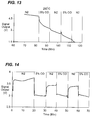
- a mixture of 89.5 percent by weight tetraethoxyorthosilicate, 10.5 percent by weight palladium and 20 percent by weight based on the weight of the tetraethoxyorthosilicate and palladium of 1-propanol was prepared.
- a film of the mixture of silica and palladium was applied to a glass substrate and heat treated at 500 °C for 2 hours.
- the film thickness was about 100 ⁇ m.
- FIG. 13 and 14 show the CO response optical absorption curve between alternating 5% CO in N 2 gas at 280°C and 525°C, respectively. As shown in Figure 14 , the response to the CO gas is quick and big.
Landscapes
- Chemical & Material Sciences (AREA)
- Life Sciences & Earth Sciences (AREA)
- Physics & Mathematics (AREA)
- Chemical Kinetics & Catalysis (AREA)
- Engineering & Computer Science (AREA)
- General Physics & Mathematics (AREA)
- General Life Sciences & Earth Sciences (AREA)
- General Chemical & Material Sciences (AREA)
- Geochemistry & Mineralogy (AREA)
- Materials Engineering (AREA)
- Organic Chemistry (AREA)
- Optics & Photonics (AREA)
- Inorganic Chemistry (AREA)
- Plasma & Fusion (AREA)
- Health & Medical Sciences (AREA)
- Analytical Chemistry (AREA)
- Biochemistry (AREA)
- General Health & Medical Sciences (AREA)
- Immunology (AREA)
- Pathology (AREA)
- Investigating Or Analysing Materials By Optical Means (AREA)
- Investigating Or Analysing Materials By The Use Of Chemical Reactions (AREA)
- Optical Fibers, Optical Fiber Cores, And Optical Fiber Bundles (AREA)
Applications Claiming Priority (1)
| Application Number | Priority Date | Filing Date | Title |
|---|---|---|---|
| US11/780,701 US7720321B2 (en) | 2007-07-20 | 2007-07-20 | Fiber optic sensor and method for making |
Publications (2)
| Publication Number | Publication Date |
|---|---|
| EP2017659A1 EP2017659A1 (en) | 2009-01-21 |
| EP2017659B1 true EP2017659B1 (en) | 2016-03-30 |
Family
ID=39942788
Family Applications (1)
| Application Number | Title | Priority Date | Filing Date |
|---|---|---|---|
| EP08156110.2A Ceased EP2017659B1 (en) | 2007-07-20 | 2008-05-13 | A fibre optic sensor and method for making |
Country Status (4)
| Country | Link |
|---|---|
| US (1) | US7720321B2 (enExample) |
| EP (1) | EP2017659B1 (enExample) |
| JP (1) | JP5025561B2 (enExample) |
| CN (1) | CN101349649B (enExample) |
Families Citing this family (8)
| Publication number | Priority date | Publication date | Assignee | Title |
|---|---|---|---|---|
| US8019190B2 (en) | 2009-03-30 | 2011-09-13 | General Electric Company | Optical sensors, systems, and methods of making |
| US8135247B2 (en) * | 2009-03-30 | 2012-03-13 | General Electric Company | Packaged sensors and harsh environment systems with packaged sensors |
| CA2819144C (en) * | 2010-12-01 | 2019-06-04 | 1366 Technologies Inc. | Making semiconductor bodies from molten material using a free-standing interposer sheet |
| US20190025492A1 (en) * | 2016-01-29 | 2019-01-24 | Corning Incorporated | Optical fiber apparatus with high divergence angle and light source system using same |
| JP6915859B2 (ja) * | 2017-08-08 | 2021-08-04 | 学校法人 創価大学 | 光ファイバ水素センサ及びその製造方法 |
| CN108645827B (zh) * | 2018-05-11 | 2021-06-22 | 武汉理工大学 | 基于简化微结构光纤的超灵敏no传感器 |
| GB2615737A (en) * | 2021-12-23 | 2023-08-23 | Oxsensis Ltd | Optical sensor |
| JP7081864B1 (ja) * | 2021-12-24 | 2022-06-07 | 株式会社ヒキフネ | 被膜ファイバ、センサ装置、モニタリング装置及び被膜ファイバの製造方法 |
Citations (2)
| Publication number | Priority date | Publication date | Assignee | Title |
|---|---|---|---|---|
| US6535658B1 (en) * | 2000-08-15 | 2003-03-18 | Optech Ventures, Llc | Hydrogen sensor apparatus and method of fabrication |
| US6819811B1 (en) * | 2000-11-09 | 2004-11-16 | Quantum Group Inc. | Nano-size gas sensor systems |
Family Cites Families (17)
| Publication number | Priority date | Publication date | Assignee | Title |
|---|---|---|---|---|
| US5280172A (en) * | 1991-11-12 | 1994-01-18 | Gaz De France | Fiber optic sensor for measuring gas |
| US5496997A (en) * | 1994-01-03 | 1996-03-05 | Pope; Edward J. A. | Sensor incorporating an optical fiber and a solid porous inorganic microsphere |
| US5457313A (en) * | 1994-02-01 | 1995-10-10 | The United States Of America As Represented By The United States Department Of Energy. | Fiber optic detector and method for using same for detecting chemical species |
| US5567622A (en) * | 1995-07-05 | 1996-10-22 | The Aerospace Corporation | Sensor for detection of nitrogen dioxide and nitrogen tetroxide |
| US5656241A (en) * | 1995-09-07 | 1997-08-12 | Optical Sensors Incorporated | Method for manufacturing fiber optic sensors |
| US5864641A (en) * | 1997-04-11 | 1999-01-26 | F&S, Inc. | Optical fiber long period sensor having a reactive coating |
| US6445861B1 (en) * | 2000-08-18 | 2002-09-03 | The United States Of America As Represented By The Administrator Of The National Aeronautics And Space Administration | Sol-gel processing to form doped sol-gel monoliths inside hollow core optical fiber and sol-gel core fiber devices made thereby |
| FR2813393B1 (fr) * | 2000-08-22 | 2002-10-18 | Commissariat Energie Atomique | Fabrication d'un capteur chimique a fibre optique comprenant un indicateur colore, utilisable notamment pour la mesure de l'acidite nitrique |
| US7058243B2 (en) * | 2002-01-17 | 2006-06-06 | Mississippi State University | Optical fiber sensor having a sol-gel fiber core and a method of making |
| JP2004309354A (ja) * | 2003-04-08 | 2004-11-04 | Nippon Steel Corp | 光学式物質センサーおよびモニタリング方法 |
| US7037554B2 (en) * | 2003-06-30 | 2006-05-02 | Mississippi State University | Moisture sensor based on evanescent wave light scattering by porous sol-gel silica coating |
| US20060008677A1 (en) * | 2004-07-12 | 2006-01-12 | General Electric Company | Ceramic bonding composition, method of making, and article of manufacture incorporating the same |
| US7421162B2 (en) * | 2005-03-22 | 2008-09-02 | General Electric Company | Fiber optic sensing device and method of making and operating the same |
| US20060222762A1 (en) * | 2005-03-29 | 2006-10-05 | Mcevoy Kevin P | Inorganic waveguides and methods of making same |
| US7228017B2 (en) * | 2005-09-30 | 2007-06-05 | General Electric Company | Fiber optic sensing device and method of making and operating the same |
| US7151872B1 (en) * | 2005-11-22 | 2006-12-19 | General Electric Company | Method, system and module for monitoring a power generating system |
| CN101109664A (zh) * | 2007-08-21 | 2008-01-23 | 李亚滨 | 光纤温/湿度传感器及其制造方法和计量装置 |
-
2007
- 2007-07-20 US US11/780,701 patent/US7720321B2/en not_active Expired - Fee Related
-
2008
- 2008-05-13 EP EP08156110.2A patent/EP2017659B1/en not_active Ceased
- 2008-05-16 JP JP2008129851A patent/JP5025561B2/ja not_active Expired - Fee Related
- 2008-05-20 CN CN2008101005134A patent/CN101349649B/zh not_active Expired - Fee Related
Patent Citations (2)
| Publication number | Priority date | Publication date | Assignee | Title |
|---|---|---|---|---|
| US6535658B1 (en) * | 2000-08-15 | 2003-03-18 | Optech Ventures, Llc | Hydrogen sensor apparatus and method of fabrication |
| US6819811B1 (en) * | 2000-11-09 | 2004-11-16 | Quantum Group Inc. | Nano-size gas sensor systems |
Also Published As
| Publication number | Publication date |
|---|---|
| US20090022449A1 (en) | 2009-01-22 |
| JP2009025289A (ja) | 2009-02-05 |
| CN101349649B (zh) | 2013-05-29 |
| JP5025561B2 (ja) | 2012-09-12 |
| CN101349649A (zh) | 2009-01-21 |
| US7720321B2 (en) | 2010-05-18 |
| EP2017659A1 (en) | 2009-01-21 |
Similar Documents
| Publication | Publication Date | Title |
|---|---|---|
| EP2017659B1 (en) | A fibre optic sensor and method for making | |
| Corres et al. | Optical fiber humidity sensors using nanostructured coatings of SiO $ _ {2} $ nanoparticles | |
| CN102483337B (zh) | 一种光纤传感器及制造方法 | |
| Ohodnicki et al. | Plasmonic nanocomposite thin film enabled fiber optic sensors for simultaneous gas and temperature sensing at extreme temperatures | |
| Yeo et al. | Fibre-optic sensor technologies for humidity and moisture measurement | |
| Lokman et al. | Optical fiber relative humidity sensor based on inline Mach–Zehnder interferometer with ZnO nanowires coating | |
| CN113916438B (zh) | 消除温度干扰的法珀干涉光纤压力传感器及其制作方法 | |
| JPH02167448A (ja) | 光学センサとその製造方法 | |
| CN107449757A (zh) | 高灵敏度及稳定度的光纤消逝场氢浓度传感器及制备方法 | |
| Wang et al. | Humidity Sensor Based on Fiber BraggGratingCoated With DifferentPore-FoamingAgentDopedPolyimides | |
| JP2009025289A5 (enExample) | ||
| Pisco et al. | A Novel Optochemical Sensor Based on SnO_2 Sensitive Thin Film for ppm Ammonia Detection in Liquid Environment | |
| Galbarra et al. | Ammonia optical fiber sensor based on self-assembled zirconia thin films | |
| CN119533533B (zh) | 石质文物裂隙填充浆料固化过程参数原位在线检测方法 | |
| Azad et al. | Tapered optical fiber coated with ZnO nanorods for detection of ethanol concentration in water | |
| Gao et al. | (3-Aminopropyl) triethoxysilane-based immobilization of Pt/WO3 on a microfiber sensor for high sensitivity hydrogen sensing | |
| EP0575408B1 (en) | A waveguide sensor | |
| Badini et al. | Sol-gel properties for fiber optic sensor applications | |
| Villar et al. | Fiber-optic chemical nanosensors by electrostatic molecular self-assembly | |
| Hussain et al. | Intensity-based Humidity Sensor through Surface Etching of POF by Femtosecond laser | |
| Corres et al. | Optical fibre humidity sensors using nano-films | |
| Ramotar et al. | Nanoscale Porous Silica Sensing Layers on Tilted FBGs made by Flame Spray Pyrolysis | |
| CN221666952U (zh) | 一种光纤光栅传感器 | |
| CN121090468A (zh) | 一种基于湿敏复合薄膜的光纤线圈型谐振腔温湿度传感器及其制备方法 | |
| Negi et al. | Novel TiO 2-GO Nanocomposite-Based Ultrahigh Sensitive Optical Fiber Humidity Sensor |
Legal Events
| Date | Code | Title | Description |
|---|---|---|---|
| PUAI | Public reference made under article 153(3) epc to a published international application that has entered the european phase |
Free format text: ORIGINAL CODE: 0009012 |
|
| AK | Designated contracting states |
Kind code of ref document: A1 Designated state(s): AT BE BG CH CY CZ DE DK EE ES FI FR GB GR HR HU IE IS IT LI LT LU LV MC MT NL NO PL PT RO SE SI SK TR |
|
| AX | Request for extension of the european patent |
Extension state: AL BA MK RS |
|
| 17P | Request for examination filed |
Effective date: 20090721 |
|
| 17Q | First examination report despatched |
Effective date: 20090814 |
|
| AKX | Designation fees paid |
Designated state(s): CH DE GB IT LI |
|
| RBV | Designated contracting states (corrected) |
Designated state(s): CH DE GB IT LI |
|
| GRAP | Despatch of communication of intention to grant a patent |
Free format text: ORIGINAL CODE: EPIDOSNIGR1 |
|
| INTG | Intention to grant announced |
Effective date: 20151130 |
|
| GRAS | Grant fee paid |
Free format text: ORIGINAL CODE: EPIDOSNIGR3 |
|
| GRAA | (expected) grant |
Free format text: ORIGINAL CODE: 0009210 |
|
| AK | Designated contracting states |
Kind code of ref document: B1 Designated state(s): CH DE GB IT LI |
|
| REG | Reference to a national code |
Ref country code: GB Ref legal event code: FG4D |
|
| REG | Reference to a national code |
Ref country code: CH Ref legal event code: EP |
|
| REG | Reference to a national code |
Ref country code: DE Ref legal event code: R096 Ref document number: 602008043145 Country of ref document: DE |
|
| REG | Reference to a national code |
Ref country code: DE Ref legal event code: R097 Ref document number: 602008043145 Country of ref document: DE |
|
| PLBE | No opposition filed within time limit |
Free format text: ORIGINAL CODE: 0009261 |
|
| STAA | Information on the status of an ep patent application or granted ep patent |
Free format text: STATUS: NO OPPOSITION FILED WITHIN TIME LIMIT |
|
| 26N | No opposition filed |
Effective date: 20170103 |
|
| PGFP | Annual fee paid to national office [announced via postgrant information from national office to epo] |
Ref country code: CH Payment date: 20180601 Year of fee payment: 11 Ref country code: DE Payment date: 20180529 Year of fee payment: 11 |
|
| PGFP | Annual fee paid to national office [announced via postgrant information from national office to epo] |
Ref country code: IT Payment date: 20180522 Year of fee payment: 11 |
|
| PGFP | Annual fee paid to national office [announced via postgrant information from national office to epo] |
Ref country code: GB Payment date: 20180529 Year of fee payment: 11 |
|
| REG | Reference to a national code |
Ref country code: DE Ref legal event code: R119 Ref document number: 602008043145 Country of ref document: DE |
|
| REG | Reference to a national code |
Ref country code: CH Ref legal event code: PL |
|
| GBPC | Gb: european patent ceased through non-payment of renewal fee |
Effective date: 20190513 |
|
| PG25 | Lapsed in a contracting state [announced via postgrant information from national office to epo] |
Ref country code: CH Free format text: LAPSE BECAUSE OF NON-PAYMENT OF DUE FEES Effective date: 20190531 Ref country code: LI Free format text: LAPSE BECAUSE OF NON-PAYMENT OF DUE FEES Effective date: 20190531 |
|
| PG25 | Lapsed in a contracting state [announced via postgrant information from national office to epo] |
Ref country code: DE Free format text: LAPSE BECAUSE OF NON-PAYMENT OF DUE FEES Effective date: 20191203 Ref country code: IT Free format text: LAPSE BECAUSE OF NON-PAYMENT OF DUE FEES Effective date: 20190513 Ref country code: GB Free format text: LAPSE BECAUSE OF NON-PAYMENT OF DUE FEES Effective date: 20190513 |