EP2017614A2 - Verfahren zur Steuerung von Lötstellen - Google Patents
Verfahren zur Steuerung von Lötstellen Download PDFInfo
- Publication number
- EP2017614A2 EP2017614A2 EP08160609A EP08160609A EP2017614A2 EP 2017614 A2 EP2017614 A2 EP 2017614A2 EP 08160609 A EP08160609 A EP 08160609A EP 08160609 A EP08160609 A EP 08160609A EP 2017614 A2 EP2017614 A2 EP 2017614A2
- Authority
- EP
- European Patent Office
- Prior art keywords
- welding
- probe
- flaw
- scanning
- analysis according
- Prior art date
- Legal status (The legal status is an assumption and is not a legal conclusion. Google has not performed a legal analysis and makes no representation as to the accuracy of the status listed.)
- Withdrawn
Links
- 238000003466 welding Methods 0.000 title claims abstract description 102
- 238000000034 method Methods 0.000 title claims abstract description 53
- 239000000523 sample Substances 0.000 claims abstract description 82
- 238000004458 analytical method Methods 0.000 claims abstract description 34
- 239000000463 material Substances 0.000 claims abstract description 21
- 238000001514 detection method Methods 0.000 claims description 15
- 238000005259 measurement Methods 0.000 claims description 4
- 230000033001 locomotion Effects 0.000 description 8
- 238000005493 welding type Methods 0.000 description 7
- 238000012360 testing method Methods 0.000 description 5
- 230000008569 process Effects 0.000 description 4
- 238000007796 conventional method Methods 0.000 description 3
- 230000003111 delayed effect Effects 0.000 description 3
- 230000008901 benefit Effects 0.000 description 2
- 238000004364 calculation method Methods 0.000 description 2
- 230000005684 electric field Effects 0.000 description 2
- 230000005670 electromagnetic radiation Effects 0.000 description 2
- 238000011156 evaluation Methods 0.000 description 2
- 230000006872 improvement Effects 0.000 description 2
- 230000007257 malfunction Effects 0.000 description 2
- 238000007747 plating Methods 0.000 description 2
- 230000011664 signaling Effects 0.000 description 2
- 206010001488 Aggression Diseases 0.000 description 1
- OKTJSMMVPCPJKN-UHFFFAOYSA-N Carbon Chemical compound [C] OKTJSMMVPCPJKN-UHFFFAOYSA-N 0.000 description 1
- 230000009471 action Effects 0.000 description 1
- 230000004913 activation Effects 0.000 description 1
- 230000016571 aggressive behavior Effects 0.000 description 1
- 230000004075 alteration Effects 0.000 description 1
- 238000013459 approach Methods 0.000 description 1
- 230000002238 attenuated effect Effects 0.000 description 1
- 230000005540 biological transmission Effects 0.000 description 1
- 230000015572 biosynthetic process Effects 0.000 description 1
- 238000007664 blowing Methods 0.000 description 1
- 229910052799 carbon Inorganic materials 0.000 description 1
- 238000005266 casting Methods 0.000 description 1
- 239000003818 cinder Substances 0.000 description 1
- 238000010276 construction Methods 0.000 description 1
- 230000007797 corrosion Effects 0.000 description 1
- 238000005260 corrosion Methods 0.000 description 1
- 230000008878 coupling Effects 0.000 description 1
- 238000010168 coupling process Methods 0.000 description 1
- 238000005859 coupling reaction Methods 0.000 description 1
- 230000001066 destructive effect Effects 0.000 description 1
- 238000005516 engineering process Methods 0.000 description 1
- 239000000835 fiber Substances 0.000 description 1
- 230000004927 fusion Effects 0.000 description 1
- 230000036541 health Effects 0.000 description 1
- 238000007689 inspection Methods 0.000 description 1
- 229910001095 light aluminium alloy Inorganic materials 0.000 description 1
- 230000004807 localization Effects 0.000 description 1
- 239000000203 mixture Substances 0.000 description 1
- 229910001172 neodymium magnet Inorganic materials 0.000 description 1
- 230000035515 penetration Effects 0.000 description 1
- 238000007639 printing Methods 0.000 description 1
- 238000002601 radiography Methods 0.000 description 1
- 238000012552 review Methods 0.000 description 1
- 239000007787 solid Substances 0.000 description 1
- 125000006850 spacer group Chemical group 0.000 description 1
- 238000013518 transcription Methods 0.000 description 1
- 230000035897 transcription Effects 0.000 description 1
- 230000000007 visual effect Effects 0.000 description 1
Images
Classifications
-
- G—PHYSICS
- G01—MEASURING; TESTING
- G01N—INVESTIGATING OR ANALYSING MATERIALS BY DETERMINING THEIR CHEMICAL OR PHYSICAL PROPERTIES
- G01N29/00—Investigating or analysing materials by the use of ultrasonic, sonic or infrasonic waves; Visualisation of the interior of objects by transmitting ultrasonic or sonic waves through the object
- G01N29/04—Analysing solids
- G01N29/06—Visualisation of the interior, e.g. acoustic microscopy
- G01N29/0654—Imaging
-
- G—PHYSICS
- G01—MEASURING; TESTING
- G01N—INVESTIGATING OR ANALYSING MATERIALS BY DETERMINING THEIR CHEMICAL OR PHYSICAL PROPERTIES
- G01N29/00—Investigating or analysing materials by the use of ultrasonic, sonic or infrasonic waves; Visualisation of the interior of objects by transmitting ultrasonic or sonic waves through the object
- G01N29/22—Details, e.g. general constructional or apparatus details
- G01N29/26—Arrangements for orientation or scanning by relative movement of the head and the sensor
- G01N29/265—Arrangements for orientation or scanning by relative movement of the head and the sensor by moving the sensor relative to a stationary material
-
- G—PHYSICS
- G01—MEASURING; TESTING
- G01N—INVESTIGATING OR ANALYSING MATERIALS BY DETERMINING THEIR CHEMICAL OR PHYSICAL PROPERTIES
- G01N29/00—Investigating or analysing materials by the use of ultrasonic, sonic or infrasonic waves; Visualisation of the interior of objects by transmitting ultrasonic or sonic waves through the object
- G01N29/44—Processing the detected response signal, e.g. electronic circuits specially adapted therefor
- G01N29/4445—Classification of defects
-
- G—PHYSICS
- G01—MEASURING; TESTING
- G01N—INVESTIGATING OR ANALYSING MATERIALS BY DETERMINING THEIR CHEMICAL OR PHYSICAL PROPERTIES
- G01N2291/00—Indexing codes associated with group G01N29/00
- G01N2291/02—Indexing codes associated with the analysed material
- G01N2291/028—Material parameters
- G01N2291/02854—Length, thickness
-
- G—PHYSICS
- G01—MEASURING; TESTING
- G01N—INVESTIGATING OR ANALYSING MATERIALS BY DETERMINING THEIR CHEMICAL OR PHYSICAL PROPERTIES
- G01N2291/00—Indexing codes associated with group G01N29/00
- G01N2291/04—Wave modes and trajectories
- G01N2291/044—Internal reflections (echoes), e.g. on walls or defects
-
- G—PHYSICS
- G01—MEASURING; TESTING
- G01N—INVESTIGATING OR ANALYSING MATERIALS BY DETERMINING THEIR CHEMICAL OR PHYSICAL PROPERTIES
- G01N2291/00—Indexing codes associated with group G01N29/00
- G01N2291/10—Number of transducers
- G01N2291/101—Number of transducers one transducer
-
- G—PHYSICS
- G01—MEASURING; TESTING
- G01N—INVESTIGATING OR ANALYSING MATERIALS BY DETERMINING THEIR CHEMICAL OR PHYSICAL PROPERTIES
- G01N2291/00—Indexing codes associated with group G01N29/00
- G01N2291/26—Scanned objects
- G01N2291/267—Welds
- G01N2291/2675—Seam, butt welding
Definitions
- the present invention refers to a method for performing a welding analysis in a material by scanning using a ultrasonic probe, in such a manner to obtain a storage of the information acquired during such scanning.
- the invention also refers to a device adapted to display and/or store the images relative to a scan with a ultrasonic probe of a welding in a material.
- the present invention represents an improvement of the current methods of analysis in the field of welding material technology.
- Welding is a connection of solid parts whose objective is that of providing a continuity of the characteristics of the material of the parts thus joined.
- welding implies the fusion of the parts being joined, reducing the volumetric or planar discontinuities (hereinafter also referred to as "flaw") inside the welded joint and in the adjacent area thermally altered to the maximum.
- flaw volumetric or planar discontinuities
- Welding is mainly used for providing vessels subjected to substantial stresses, mainly due to pressure as, for example, in the case of pipes or boiler elements, or for the construction of more or less complex support structures (carpentry) or for shipbuilding.
- the welded joints are subjected to more or less extensive nondestructive tests depending on the reliability required of the joint. Such tests are extremely critical, require a lot of time and use of special equipment.
- the operating principle of such techniques is based on the alterations that the electromagnetic radiations are subjected to when they encounter a flaw on their path inside the material.
- the photographing process creates a bidimensional image of the radiographed object.
- the thickness, density and composition variations of the object are displayed as image density variations (in practice grey-scale variations).
- the evaluation is performed by comparing the variations of the radiographic density with the known characteristics of the object, or with radiographic standards produced by the same object of acceptable quality.
- the position of a flaw in the volume of the piece cannot be determined means of a single exposure and the depth in the direction of the rays cannot be determined in an accurate manner.
- the radiographic analysis are also disadvantageous given that they require the interruption of the operations, thus leading to wasting time, as well as not being able to develop the results of the tests in real time.
- the inspection of the weldings by means of ultrasonics instead is a nondestructive method in which the highfrequency sound waves are introduced into the material to be tested, in order to highlight surface or interior flaws, measure the thickness of the materials as well as the distance and the dimension of the various flaws.
- the ultrasonics technique is essentially based on the phenomenon of the transmission of an acoustic wave in the material.
- Ultrasonics are elastic vibration waves with frequency typically between 1 and 10 MHz; however, for some applications, the field can be extended from 20 KHz up to over 200 MHz.
- Ultrasonic waves are generated by exploiting the piezoelectric properties of some materials; these properties consist in the capacity of these materials to contract and riexpand upon subjection to the action of an electric field. If the electric field has a suitable frequency, the vibrations of the material produce elastic waves of ultrasonic frequency.
- the localization and the dimensioning of the flaws is usually performed by means of a correlation process between the ultrasonic beam features, the physical and geometric features of the material, the parameters (amplitude and pulse delay) and the coordinates of the scanning trajectory.
- a further drawback of a conventional method of analysis with ultrasonic waves consists in the fact that the operator usually records manually, in real time, on a conventional service paper, the information regarding the signals as they are detected, with the concrete possibility of mistakes or incomplete transcription of the information gathered, as well as an unacceptable approximation of the detection starting point and end point of the flaws that are used for measuring of the same flaws.
- the object of the present invention is that of overcoming the abovementioned drawbacks by developing a welding analysis method through ultrasonic waves which is easy to use, inexpensive and capable of ensuring a good reliability and good quality of results.
- this problem is solved through a method for performing a welding analysis in a material, defined in claim 1 attached.
- the term "information detected during said scanning” means that the images, the continuous sequences of the subsequent images (thus forming a video) corresponding to the various sections of the welding as detected by means of said scanning, as well as alphanumeric data regarding the type of scanning performed, material type, welding type, position and dimensions of the flaws observed in said welding.
- said information comprises continuous sequences of subsequent images (forming a video) detected during said scanning.
- said image sequences are detected and transmitted by said at least one probe, they are displayed on a ultrasonic flaw detector connected to said at least one acquisition unit.
- said image sequences are stored on at least one video acquisition unit in the standard graphic format, for example JPEG, MPEG, WMV, and other digital and/or analogue format typically known by men skilled in the art.
- standard graphic format for example JPEG, MPEG, WMV, and other digital and/or analogue format typically known by men skilled in the art.
- said probe used in said method comprises a transducer element for producing and detecting ultrasonic waves.
- said transducer element comprises a piezoelectric element, representing the active element of the probe, adapted to generate an electric charge when subjected to deformation. Furthermore, said piezoelectric element is also adapted to deform when subjected to an electric charge.
- an element for measuring the angular position and the axial position in short referred to as "encoder” hereinafter, is connected to said probe, in such a manner that each movement of the probe corresponds to an analogous movement of the encoder, which converts the measurements taken into electrical signals.
- encoder is also connected to said at least one acquisition unit.
- said step a) of the method of the present invention further comprises the steps of:
- said step a1) is performed by means of a first counter connected to said encoder, said first counter being activated when said scanning of the welding starts.
- said first counter records the initial position of the encoder, corresponding to the position assumed by the probe with respect to the welding when the scanning of the welding itself starts.
- a counter is a device adapted to record the number of times a particular event or process occurs.
- the device can be of the mechanical, electromechanical or electronic type.
- the method according to the present invention allows analysing, by means of ultrasonic probes, any type of welding, such as for example the "linear” ones, that is the type of weldings that do not require the calculation of the distance of the probe from the welding axis, such as for example for circumferential and longitudinal weldings for vessels or pipes, and the "circular” weldings, that is the type of weldings for which the value of the distance detected by the probe must be related to the distances of the indications from said initial position of the probe, such as for example for weldings between vessel nozzles and platings or plate/pipe couplings.
- any type of welding such as for example the "linear” ones, that is the type of weldings that do not require the calculation of the distance of the probe from the welding axis, such as for example for circumferential and longitudinal weldings for vessels or pipes, and the “circular” weldings, that is the type of weldings for which the value of the distance detected by the probe must be related to the distances of the indications from said initial position of the probe
- step a2) of the method of the present invention said at least one probe is moved from said initial reference position to a position for detecting information regarding the welding.
- said probe is moved by means of a motor.
- said probe can also be moved by means of other conventional methods known in the art.
- said step a2) further comprises the subsequent movement of said detection position to new positions for detecting information regarding the welding, up to the completion of said scanning of the welding.
- said first counter detects (step a3) each of said new detection positions assumed by said at least one probe during said step a2).
- said first counter detects all the detection positions assumed by said at least one probe during scanning of the welding, with the advantage that such positions can be checked and analysed at any time, in particular at the end of the scanning.
- the image sequences, detected and transmitted by said at least one probe when the probe itself is at said detection positions are displayed on said ultrasonic flaw detector and stored on said at least one video acquisition unit.
- the data detected by said first counter regarding the positions of said at least one probe when scanning and the image sequence stored by said at least one acquisition unit integrate contributing to the formation of a complete information framework regarding the welding that were subjected to scanning.
- said method when said at least one probe, during said scanning, checks for the presence of a flaw in said welding, said method further comprises the steps of d) measuring the dimension of said flaw.
- said step d) comprises the steps of:
- the position of the probe with respect to the point at which the start of the flaw is detected is recorded, so as to have a first point of reference useful for measuring the flaw itself.
- said steps d1) and d2) are performed by means of a second counter.
- the dimension of the flaw is measured taking into account the longitudinal distance between the "start flaw” and “end flaw” positions, as detected by said second counter, and the measurement of the depth of the flaw available by means of said ultrasonic flaw detector.
- the identification and dimensioning of the flaws also generally occurs through a correlation process between the characteristics of the ultrasonic beam, the physical and geometric characteristics of the material, the parameters (amplitude and pulse delay) and the coordinates of the scanning trajectory.
- the dimensions of said flaws are compared with the flaw parameters predefined in compliance with the applicable international codes, such as for example ASME div. 1&2, ASME 2235-9, and EN 1712-1713-1714.
- the image sequence regarding the welding sections in which the presence of said flaw had been detected are stored on at least one video acquisition unit.
- the method of the present invention comprises the further steps of printing, on a medium, some photograms of the stored images deemed particularly relevant, such as for example images bearing welding flaws.
- the method of the present invention can also be used to analyse weldings made up of several components. In case, at the end of a first scanning by means of said probe, all the components of the welding have not been analysed, the method of the present invention is repeated for a number of times necessary for the detection of the information regarding the remaining welding component/s to be analysed.
- the present invention refers to a device as defined in claim 15 attached.
- a device adapted to store the images and/or image sequences detected during at least one scanning by means of at least one ultrasonic probe of a welding in a material, said device comprises a video acquisition adapted to be connected to ultrasonic flaw detector, is capable of allowing a visual control of the various sections of the analysed welding.
- said device allows the possibility to display said image sequences again at will.
- said image sequences were detected by said at least one probe during the scanning of welding sections in which flaws were detected.
- said device according to the present invention is connected to an element for measuring the angular and/or axial position (referred to as "encoder"), in turn connected to said at least one probe, in such a manner that each movement of the probe corresponds to an analogous movement of the encoder.
- encoder an element for measuring the angular and/or axial position
- said encoder and said one probe are accommodated in a moveable element, such as for example a carriage.
- said moveable element comprises at least one wheel comprising magnets.
- Said video acquisition unit comprises typical elements and accessories of such unit, such as for example a colour video, battery power supply and/or by means of 110/220 V 50/60 Hz through connections with a suitable cable, on/off button, keyboard, mouse, video output, USB connection and network connection.
- some of said elements and accessories of the video acquisition unit are IP65 watertight.
- said acquisition unit is capable of operating both indoors and outdoors.
- said video acquisition unit comprises further operation elements or buttons, such as for example buttons for resetting the encoder, connection between the video acquisition unit and encoder, LED for signalling malfunctions of the encoder management card.
- said video acquisition unit is connected to said ultrasonic flaw detector by means of an interface represented by a video output of if VGA or analogue type.
- Said ultrasonic flaw detector can be any type of apparatus used for conventional analysis of weldings by means of ultrasonic probes provided with the aforementioned interfaces.
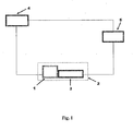
- an ultrasonic probe 1 comprises a transducer element which in turn comprises a piezoelectric element (not shown in the figure), is arranged on probe-bearing carriage 2 in order to perform a scanning by means of ultrasonic waves of a welding.
- Such welding in this first embodiment, is of the linear type (for example used in a pipe) and it is made up of a single component.
- Such probe-bearing carriage 2 is also provided with an encoder 3, connected to said probe 1 in such a manner the each movement of the probe 1 corresponds to an analogous movement of the encoder 3.
- the probe-bearing carriage 2 is made of light aluminium alloys and carbon fibre to guarantee rigidity and lightness at the same time and it is provided with two wheels (not shown), arranged on the opposite side of the encoder 3 and enclosing two permanent neodymium magnets, in such a manner to maintain the probe-bearing carriage 2 easily aligned with respect to the welding, thus also guaranteeing the distance of the of the transducer with respect to the welding.
- such encoder 3 is connected to the video acquisition unit 5 and to a ultrasonic flaw detector 4.
- the video acquisition unit 5 comprises (not shown in the figure), on the front side, an 8 inch LCD video, a button for resetting a first counter, a button for resetting a second counter, a connection to the second counter, a LED for signalling malfunctions in the control of such counters, a network connection and USB connections, 12V outputs, and, at the rear side, a VGA video output, the 110/220 V 50/60 Hz power supply and the on/off button.
- the ultrasonic flaw detector 4 in particular is provided with a monitor, mouse and keyboard (not shown in the figure).
- the welding to be analysed being of the linear type
- calculation of the distance of the probe from the axis of the welding is not required for setting the initial reference position of the probe 1 in an efficient manner with respect to the welding.
- the method of the present invention comprises the activation of a first counter connected to said encoder 3, in such a manner to detect the reference position of the probe 1 when the analysis of the welding starts (reference point 0). Such reference position can be observed on the video acquisition unit 5.
- the probe bearing carriage 2 provided with a ultrasonic probe 1 and an encoder 3 is arranged in proximity to a welding, in such a manner that the axis of the transducer is at the reference point 0.
- the probe-bearing carriage 2 is moved, thus effectively starting the scanning of the welding component to be analysed by means of the ultrasonic probe 3.
- the first counter detects their new positions making the visible on the video acquisition unit 5.
- the probe 1 is moved back up to the point at which the presence of the flaw is observed; then, a second counter which records the reference position of the probe 1 is activated at the precise point at which the flaw to be analysed was first observed.
- the second counter After the second counter has been activated, scanning restarts along the original direction until it determines a point at which the flaw is no longer observed.
- the probe 1 In order to establish the final point of the flaw, analogously to the operation carried out above to establish in an accurate manner the initial reference point of the flaw, the probe 1 is taken back to the point at which the presence of the flaw is no longer observed.
- the second counter records the position of the probe 1 at said final point of the flaw. It is thus possible to calculate the length of the flaw, knowing the initial and final points at which the flaw itself was observed. This information, added to the one provided by the ultrasonic flaw detector 4 regarding the depth of the detected flaw, allow to calculate the shape and dimension of the flaw, also by means of a comparison with the predefined parameters of the flaws.
- the second counter Upon acquisition of the information regarding the start and end of the flaw, the second counter is reset once again and the scanning of the welding component continues to check for the presence of other flaws, repeating the operations described above, until the scanning of the entire welding component is completed.
- a second embodiment of the method of the present invention described is a method for performing a ultrasonic analysis of welding, still of the linear type, like in the first embodiment, but being made up of two components in this second embodiment.
- the method is analogous to the one described previously according to the first embodiment of the present invention, differing on the fact that two consecutive scannings are performed for the two welding components.
- the reference point 0 of the scanning of the second element shall be such to correspond to one of the last positions indicated by such first counter at the end of the scanning of the first component, in such a manner that there is a given overlapping of acquired information for the scanning of the two subsequent components. In this manner, the risk of losing some information between a scanning and the other is avoided, thus guaranteeing continuity in the acquisition of information regarding two subsequent welding components.
- a probe 1 like the one described above, is used in order to be able to perform ultrasonic waves analysis of a welding of the circular type, for example between nozzles and platings for vessels.
- the value of the distance read by the encoder must be related to the welding axis in order to be able to set the reference point 0 in a correct manner.
- a spacer is associated to the probe-bearing carriage 2 in such a manner to position the wheels onto the external surface of the nozzle.
- the method for analysing the circular type of welding in this third embodiment is analogous to the one described referring to the first embodiment for performing the scanning of the linear type of welding.
Landscapes
- Physics & Mathematics (AREA)
- General Physics & Mathematics (AREA)
- Pathology (AREA)
- Life Sciences & Earth Sciences (AREA)
- Chemical & Material Sciences (AREA)
- Analytical Chemistry (AREA)
- Biochemistry (AREA)
- Health & Medical Sciences (AREA)
- Immunology (AREA)
- General Health & Medical Sciences (AREA)
- Engineering & Computer Science (AREA)
- Acoustics & Sound (AREA)
- Signal Processing (AREA)
- Investigating Or Analyzing Materials By The Use Of Ultrasonic Waves (AREA)
- Resistance Welding (AREA)
- Lining Or Joining Of Plastics Or The Like (AREA)
Applications Claiming Priority (1)
| Application Number | Priority Date | Filing Date | Title |
|---|---|---|---|
| ITMI20071457 ITMI20071457A1 (it) | 2007-07-20 | 2007-07-20 | Metodo per il controllo delle saldature |
Publications (2)
| Publication Number | Publication Date |
|---|---|
| EP2017614A2 true EP2017614A2 (de) | 2009-01-21 |
| EP2017614A3 EP2017614A3 (de) | 2011-02-16 |
Family
ID=39930668
Family Applications (1)
| Application Number | Title | Priority Date | Filing Date |
|---|---|---|---|
| EP08160609A Withdrawn EP2017614A3 (de) | 2007-07-20 | 2008-07-17 | Verfahren zur Steuerung von Lötstellen |
Country Status (2)
| Country | Link |
|---|---|
| EP (1) | EP2017614A3 (de) |
| IT (1) | ITMI20071457A1 (de) |
Family Cites Families (3)
| Publication number | Priority date | Publication date | Assignee | Title |
|---|---|---|---|---|
| US4102203A (en) * | 1976-12-16 | 1978-07-25 | J. G. Sylvester Associates, Inc. | Underwater inspection and communication apparatus |
| US4742713A (en) * | 1984-06-01 | 1988-05-10 | Omron Tateisi Electronics Co. | Ultrasonic flaw detecting system |
| US4908774A (en) * | 1986-05-05 | 1990-03-13 | Akademiet For De Tekniske Videnskaber | System for ultrasonic examination |
-
2007
- 2007-07-20 IT ITMI20071457 patent/ITMI20071457A1/it unknown
-
2008
- 2008-07-17 EP EP08160609A patent/EP2017614A3/de not_active Withdrawn
Also Published As
| Publication number | Publication date |
|---|---|
| EP2017614A3 (de) | 2011-02-16 |
| ITMI20071457A1 (it) | 2009-01-21 |
Similar Documents
| Publication | Publication Date | Title |
|---|---|---|
| CN106352910B (zh) | 无损检测设备的自动校准 | |
| EP3596456B1 (de) | Verfahren zum prüfen einer punktschweissung mittels eines gruppenstrahlerprüfkopfes | |
| US5161413A (en) | Apparatus and method for guided inspection of an object | |
| JP6290718B2 (ja) | 超音波検査装置及び超音波検査方法 | |
| EP3287778B1 (de) | System und verfahren zur zerstörungsfreien beurteilung eines testobjekts durch akustische thermographie | |
| EP0416245B1 (de) | Ultraschallsystem zur Bestimmung des Profils von Festkörpern | |
| JP2007187593A (ja) | 配管検査装置及び配管検査方法 | |
| US5108693A (en) | Non-destructive dimensional and flaw inspection of thin wall tube weldments | |
| WO2012008144A1 (ja) | 超音波探傷装置および超音波探傷方法 | |
| JP2023520133A (ja) | ポータブル超音波検査のためのシステムおよび方法 | |
| JP5916864B2 (ja) | 未溶着量の測定方法及び超音波探傷装置 | |
| US9823224B2 (en) | Weld inspection method and system | |
| JP3713007B2 (ja) | 超音波検査装置 | |
| EP2017614A2 (de) | Verfahren zur Steuerung von Lötstellen | |
| CN109507296A (zh) | 一种核反应堆控制棒驱动机构密封焊缝的超声波检测方法 | |
| US11933766B2 (en) | Material profiling for improved sizing accuracy | |
| KR101487902B1 (ko) | 초음파 탐상을 이용한 배관 내의 가스축적량 산출장치 및 산출방법 | |
| JP4559931B2 (ja) | 超音波探傷方法 | |
| JP5959677B2 (ja) | 超音波探傷装置および超音波探傷方法 | |
| JP2007322350A (ja) | 超音波探傷装置及び方法 | |
| JP2004205303A (ja) | 損傷の評価方法および評価システム | |
| JPH03128457A (ja) | 反射特性目視方法 | |
| Pfeiffer et al. | Identification of impact damage in sandwich composites by acoustic camera detection of leaky Lamb wave mode conversions | |
| JP2025073840A (ja) | 非破壊検査システム及び非破壊検査方法 | |
| Passi et al. | High-reliability manual ultrasonic inspection |
Legal Events
| Date | Code | Title | Description |
|---|---|---|---|
| PUAI | Public reference made under article 153(3) epc to a published international application that has entered the european phase |
Free format text: ORIGINAL CODE: 0009012 |
|
| AK | Designated contracting states |
Kind code of ref document: A2 Designated state(s): AT BE BG CH CY CZ DE DK EE ES FI FR GB GR HR HU IE IS IT LI LT LU LV MC MT NL NO PL PT RO SE SI SK TR |
|
| AX | Request for extension of the european patent |
Extension state: AL BA MK RS |
|
| PUAL | Search report despatched |
Free format text: ORIGINAL CODE: 0009013 |
|
| AK | Designated contracting states |
Kind code of ref document: A3 Designated state(s): AT BE BG CH CY CZ DE DK EE ES FI FR GB GR HR HU IE IS IT LI LT LU LV MC MT NL NO PL PT RO SE SI SK TR |
|
| AX | Request for extension of the european patent |
Extension state: AL BA MK RS |
|
| STAA | Information on the status of an ep patent application or granted ep patent |
Free format text: STATUS: THE APPLICATION IS DEEMED TO BE WITHDRAWN |
|
| 18D | Application deemed to be withdrawn |
Effective date: 20110201 |