EP2017474B1 - Transmission for a wind turbine - Google Patents
Transmission for a wind turbine Download PDFInfo
- Publication number
- EP2017474B1 EP2017474B1 EP08002608.1A EP08002608A EP2017474B1 EP 2017474 B1 EP2017474 B1 EP 2017474B1 EP 08002608 A EP08002608 A EP 08002608A EP 2017474 B1 EP2017474 B1 EP 2017474B1
- Authority
- EP
- European Patent Office
- Prior art keywords
- planet carrier
- bearing
- transmission
- rotor
- housing
- Prior art date
- Legal status (The legal status is an assumption and is not a legal conclusion. Google has not performed a legal analysis and makes no representation as to the accuracy of the status listed.)
- Active
Links
Images


Classifications
-
- F—MECHANICAL ENGINEERING; LIGHTING; HEATING; WEAPONS; BLASTING
- F03—MACHINES OR ENGINES FOR LIQUIDS; WIND, SPRING, OR WEIGHT MOTORS; PRODUCING MECHANICAL POWER OR A REACTIVE PROPULSIVE THRUST, NOT OTHERWISE PROVIDED FOR
- F03D—WIND MOTORS
- F03D15/00—Transmission of mechanical power
- F03D15/10—Transmission of mechanical power using gearing not limited to rotary motion, e.g. with oscillating or reciprocating members
-
- F—MECHANICAL ENGINEERING; LIGHTING; HEATING; WEAPONS; BLASTING
- F01—MACHINES OR ENGINES IN GENERAL; ENGINE PLANTS IN GENERAL; STEAM ENGINES
- F01D—NON-POSITIVE DISPLACEMENT MACHINES OR ENGINES, e.g. STEAM TURBINES
- F01D11/00—Preventing or minimising internal leakage of working-fluid, e.g. between stages
- F01D11/001—Preventing or minimising internal leakage of working-fluid, e.g. between stages for sealing space between stator blade and rotor
-
- F—MECHANICAL ENGINEERING; LIGHTING; HEATING; WEAPONS; BLASTING
- F03—MACHINES OR ENGINES FOR LIQUIDS; WIND, SPRING, OR WEIGHT MOTORS; PRODUCING MECHANICAL POWER OR A REACTIVE PROPULSIVE THRUST, NOT OTHERWISE PROVIDED FOR
- F03D—WIND MOTORS
- F03D15/00—Transmission of mechanical power
-
- F—MECHANICAL ENGINEERING; LIGHTING; HEATING; WEAPONS; BLASTING
- F03—MACHINES OR ENGINES FOR LIQUIDS; WIND, SPRING, OR WEIGHT MOTORS; PRODUCING MECHANICAL POWER OR A REACTIVE PROPULSIVE THRUST, NOT OTHERWISE PROVIDED FOR
- F03D—WIND MOTORS
- F03D80/00—Details, components or accessories not provided for in groups F03D1/00 - F03D17/00
- F03D80/70—Bearing or lubricating arrangements
-
- F—MECHANICAL ENGINEERING; LIGHTING; HEATING; WEAPONS; BLASTING
- F16—ENGINEERING ELEMENTS AND UNITS; GENERAL MEASURES FOR PRODUCING AND MAINTAINING EFFECTIVE FUNCTIONING OF MACHINES OR INSTALLATIONS; THERMAL INSULATION IN GENERAL
- F16H—GEARING
- F16H57/00—General details of gearing
- F16H57/08—General details of gearing of gearings with members having orbital motion
- F16H57/082—Planet carriers
-
- F—MECHANICAL ENGINEERING; LIGHTING; HEATING; WEAPONS; BLASTING
- F05—INDEXING SCHEMES RELATING TO ENGINES OR PUMPS IN VARIOUS SUBCLASSES OF CLASSES F01-F04
- F05B—INDEXING SCHEME RELATING TO WIND, SPRING, WEIGHT, INERTIA OR LIKE MOTORS, TO MACHINES OR ENGINES FOR LIQUIDS COVERED BY SUBCLASSES F03B, F03D AND F03G
- F05B2240/00—Components
- F05B2240/50—Bearings
-
- F—MECHANICAL ENGINEERING; LIGHTING; HEATING; WEAPONS; BLASTING
- F05—INDEXING SCHEMES RELATING TO ENGINES OR PUMPS IN VARIOUS SUBCLASSES OF CLASSES F01-F04
- F05B—INDEXING SCHEME RELATING TO WIND, SPRING, WEIGHT, INERTIA OR LIKE MOTORS, TO MACHINES OR ENGINES FOR LIQUIDS COVERED BY SUBCLASSES F03B, F03D AND F03G
- F05B2260/00—Function
- F05B2260/40—Transmission of power
- F05B2260/403—Transmission of power through the shape of the drive components
- F05B2260/4031—Transmission of power through the shape of the drive components as in toothed gearing
- F05B2260/40311—Transmission of power through the shape of the drive components as in toothed gearing of the epicyclic, planetary or differential type
-
- F—MECHANICAL ENGINEERING; LIGHTING; HEATING; WEAPONS; BLASTING
- F05—INDEXING SCHEMES RELATING TO ENGINES OR PUMPS IN VARIOUS SUBCLASSES OF CLASSES F01-F04
- F05D—INDEXING SCHEME FOR ASPECTS RELATING TO NON-POSITIVE-DISPLACEMENT MACHINES OR ENGINES, GAS-TURBINES OR JET-PROPULSION PLANTS
- F05D2240/00—Components
- F05D2240/50—Bearings
-
- F—MECHANICAL ENGINEERING; LIGHTING; HEATING; WEAPONS; BLASTING
- F05—INDEXING SCHEMES RELATING TO ENGINES OR PUMPS IN VARIOUS SUBCLASSES OF CLASSES F01-F04
- F05D—INDEXING SCHEME FOR ASPECTS RELATING TO NON-POSITIVE-DISPLACEMENT MACHINES OR ENGINES, GAS-TURBINES OR JET-PROPULSION PLANTS
- F05D2260/00—Function
- F05D2260/40—Transmission of power
- F05D2260/403—Transmission of power through the shape of the drive components
- F05D2260/4031—Transmission of power through the shape of the drive components as in toothed gearing
- F05D2260/40311—Transmission of power through the shape of the drive components as in toothed gearing of the epicyclical, planetary or differential type
-
- F—MECHANICAL ENGINEERING; LIGHTING; HEATING; WEAPONS; BLASTING
- F16—ENGINEERING ELEMENTS AND UNITS; GENERAL MEASURES FOR PRODUCING AND MAINTAINING EFFECTIVE FUNCTIONING OF MACHINES OR INSTALLATIONS; THERMAL INSULATION IN GENERAL
- F16C—SHAFTS; FLEXIBLE SHAFTS; ELEMENTS OR CRANKSHAFT MECHANISMS; ROTARY BODIES OTHER THAN GEARING ELEMENTS; BEARINGS
- F16C2300/00—Application independent of particular apparatuses
- F16C2300/10—Application independent of particular apparatuses related to size
- F16C2300/14—Large applications, e.g. bearings having an inner diameter exceeding 500 mm
-
- F—MECHANICAL ENGINEERING; LIGHTING; HEATING; WEAPONS; BLASTING
- F16—ENGINEERING ELEMENTS AND UNITS; GENERAL MEASURES FOR PRODUCING AND MAINTAINING EFFECTIVE FUNCTIONING OF MACHINES OR INSTALLATIONS; THERMAL INSULATION IN GENERAL
- F16C—SHAFTS; FLEXIBLE SHAFTS; ELEMENTS OR CRANKSHAFT MECHANISMS; ROTARY BODIES OTHER THAN GEARING ELEMENTS; BEARINGS
- F16C2360/00—Engines or pumps
- F16C2360/31—Wind motors
-
- F—MECHANICAL ENGINEERING; LIGHTING; HEATING; WEAPONS; BLASTING
- F16—ENGINEERING ELEMENTS AND UNITS; GENERAL MEASURES FOR PRODUCING AND MAINTAINING EFFECTIVE FUNCTIONING OF MACHINES OR INSTALLATIONS; THERMAL INSULATION IN GENERAL
- F16H—GEARING
- F16H57/00—General details of gearing
- F16H57/02—Gearboxes; Mounting gearing therein
- F16H57/021—Shaft support structures, e.g. partition walls, bearing eyes, casing walls or covers with bearings
-
- Y—GENERAL TAGGING OF NEW TECHNOLOGICAL DEVELOPMENTS; GENERAL TAGGING OF CROSS-SECTIONAL TECHNOLOGIES SPANNING OVER SEVERAL SECTIONS OF THE IPC; TECHNICAL SUBJECTS COVERED BY FORMER USPC CROSS-REFERENCE ART COLLECTIONS [XRACs] AND DIGESTS
- Y02—TECHNOLOGIES OR APPLICATIONS FOR MITIGATION OR ADAPTATION AGAINST CLIMATE CHANGE
- Y02E—REDUCTION OF GREENHOUSE GAS [GHG] EMISSIONS, RELATED TO ENERGY GENERATION, TRANSMISSION OR DISTRIBUTION
- Y02E10/00—Energy generation through renewable energy sources
- Y02E10/70—Wind energy
- Y02E10/72—Wind turbines with rotation axis in wind direction
Definitions
- the present invention relates to a transmission for a wind energy plant and in particular the storage of a planet carrier in the transmission of a wind turbine.
- a wind energy plant in which a two-stage planetary gear provided with a drive stage and an output stage is.
- the planet carrier of the drive stage is supported on the machine carrier or the rotor carrier and thus acts as a torque arm.
- a transmission for a wind turbine that has a two-stage planetary gear, and that discloses the preamble of claim 1.
- the planet carrier is fixed in a gear housing via two rolling bearings, which at the same time also serve to support the rotor.
- the two large rolling bearings transfer the entire wind forces acting on the rotor blades to the housing of the generator.
- the invention has for its object to provide a transmission for a wind turbine, in which on the planet carrier a simple shaft hub connection can be realized without additional components.
- the present invention relates to a transmission for a wind turbine.
- the transmission is designed as a single or multi-stage planetary gear, which has a planet carrier.
- the planet carrier is the drive side connected to a rotor shaft or a rotor hub and mounted on a bearing that within the Gear housing is provided for the planet carrier.
- the planet carrier may be mounted in the gear housing or the gear housing on the planet carrier.
- the bearing is arranged on the output side of the planet of the planet carrier in the transmission housing.
- the output side position of the bearing for the planet carrier offers a number of special advantages.
- the input and output side in the transmission housing is stored, the drive-side bearing must be provided with a large inner diameter, which increases the cost of the camp.
- a hub connection can be used, which can transmit large torques on a small diameter.
- Such shaft hub connections are complex and build large. Moreover, they are risky in the production and assembly, which ultimately strikes the costs.
- the use of a compact torque bearing is provided on the output side of the planet carrier, which serves to receive all acting between the planet carrier and gear housing moments and transverse forces.
- a rotor shaft or hub connected to the planet carrier mounted according to the invention is mounted in a manner known per se outside of the transmission.
- the planetary gear is a multi-stage planetary gear, wherein a planet carrier of the first stage is provided as the inventively mounted planet carrier.
- a moment bearing can preferably be provided a set tapered roller bearing pair.
- a three-row cylindrical roller bearing as the moment bearing.
- other embodiments for the bearing are conceivable when the bearing provides a support torque with simultaneous axial and radial guidance.
- a direct connection of the rotor shaft to the planet carrier is provided.
- a flange is expediently connected in a form-fitting manner to the rotor shaft, to which the planet carrier is screwed.
- an adapter plate may be provided for direct connection of the rotor hub to the planet carrier.
- the adapter disc is screwed to the planet carrier, wherein the rotor hub connected to the adapter disc is mounted on a support structure via a moment bearing.
- a support structure for example, serve the machine frame on which the transmission is mounted.
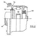
- FIG. 1 shows in a section a rotor shaft 10, which is mounted outside of the gearbox twice with a one- or two-piece rotor bearing housing (not shown).
- the gear-pointing end of the rotor shaft 10 has a Rotorwellenflansch 12 which is positively connected to the rotor shaft.
- the rotor shaft flange 12 is connected via a screw connection 14 to a planet carrier 16.
- the interior of the transmission is sealed off from the environment via a schematically illustrated sealing system 18.
- the gearbox designed as a multi-stage planetary gear has a gear housing 20 with a moment support 22. Also in FIG. 1 to recognize the integrated into the housing 20 ring gear 24 and two of the planet 26, 28.
- the sun shaft 30 leads to the sun (not shown) in the first stage of the transmission.
- the planet carrier 16 is mounted via a moment bearing 32 in the housing 20 of the transmission.
- the moment bearing 32 is located on the output side of the planet carrier 16 and is designed in the illustrated embodiment as a set tapered roller bearing pair.
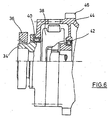
- FIG. 6 shows a hollow shaft 34 on the planet carrier, which is provided via a shrink disc 36 for connection to the rotor shaft.
- the planet carrier 38 is the drive side via a cylindrical roller bearing 40 and the output side mounted on another cylindrical roller bearing 42 in the housing 44.
- the housing 44 is the same as that in FIG FIG. 1 illustrated example with a moment support 46 on the machine frame via decoupling elements (not shown) supported.
- the two cylindrical roller bearings can also by two tapered roller bearings be replaced in X-arrangement, which are set and have a span for receiving the moments.
- FIG. 1 illustrated embodiment of the invention makes it clear that the use of a compact torque bearing on the drive side of the planet carrier creates the opportunity to realize on the drive side any rotor shaft connection.
- the moment bearing absorbs the forces acting between planet carrier and gear housing forces.
- the forces acting In the embodiments to be described below are in the embodiments with a toothed coupling according to Fig. 2 and 3 the forces acting predominantly the weight forces of the planet carrier.
- the forces acting are the weight forces of the rest of the transmission and the forces resulting from deformation of the machine frame under load forces.
- FIG. 2 shows in a sectional view a rotor shaft 48 which is connected via a toothed coupling 50 with the planet carrier 52.
- the transmission housing 54 is in the in FIG. 2 illustrated embodiment firmly connected to a component 56.
- the component 56 can either be the machine carrier or a one-piece bearing housing of a (not shown) rotor bearing.
- the gear housing 54 is not rubberized stored, but rigidly mounted and any occurring relative movements are compensated via the gear coupling 50.
- the planet carrier 52 is mounted in the housing 54 via a moment bearing 58.
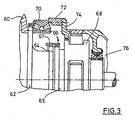
- FIG. 3 shows a further embodiment in which the transmission is bolted to a support structure and a storage of the rotor shaft also takes place via a moment bearing.
- FIG. 3 shows a rotor hub 60 which is connected to an adapter shaft 62.
- the adapter shaft 62 has at its end facing the gear an external spline 64.
- Via a toothed coupling 66 the adapter shaft 62 is coupled to the planet carrier 68.
- a hub with splines 64 and a further hub with splines 65 engage in an internally toothed coupling sleeve 67.
- the rotor hub 60 is mounted on the machine carrier 72 in a defined manner via a moment bearing 70.
- the gear housing 74 is mounted on the machine carrier 72 defines defined, with a compensation of relative movements via the toothed coupling 66 takes place.
- the planetary carrier 68 is mounted on the output side via a torque bearing 76 on the transmission housing 74.
- the rotor hub 60 and the adapter shaft 62 may be made as one piece.
- the hub with spline can optionally be designed to facilitate production of the splines as a single part and are connected via a positive connection with the rotor hub 60, 62.
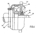
- FIG. 4 shows a further preferred embodiment, in which the transmission is designed as a slip-on.
- the rotor shaft 78 is frictionally / non-positively connected via a rotor shaft flange 80 via a screw 84 to the planet carrier 86.
- the transmission housing 90 and thus the entire transmission is mounted on the planet carrier 86 via a moment bearing 88.
- the sun 90 is used on the drive side in the planet carrier 86 during assembly of the transmission, wherein the sun 90 has a spline 92 for connection to the planet carrier of the second stage.
- the transmission housing 90 is supported via a torque arm 91.
- the sun can be used on the drive side with a corresponding dimensioning of the planet carrier and the moment bearing.
- the first column concerns the rotor bearing: Here, a distinction is made between a moment bearing for the rotor and a two-point bearing. In two-point storage, there are still cases to distinguish between a two-point bearing with a one-piece housing and a two-point mounting with a two-part housing.
- the second column indicates the connection between planet carrier and rotor shaft / hub.
- a toothed coupling which is designed as a spline and a frictional / frictional connection, as can be prepared for example by screwing.
- the third column shows the gearbox connection to the machine carrier.
- the fixed screwed to the machine frame gearbox and provided via a torque arm and a decoupling element support of the transmission. It can already be clearly seen in the table that, in the case of a fixedly bolted gear connection, the connection between planet carrier and rotor shaft / hub must take place via a toothed coupling.
- Shown in the fourth column is briefly the storage ratio of the planet carrier to gear housing and the figure, which reproduces a corresponding design.
- FIG. 5 Another embodiment is in FIG. 5 shown. This takes place as in the embodiment FIG. 3 a bearing of the rotor shaft via a moment bearing.
- the rotor hub 94 is connected via an adapter disk 96 with the planet carrier 98. The connection is frictionally and non-positively via a screw 100.
- the gear housing 105 is a moment bearing 102 mounted on the planet carrier 98 and supported on a torque arm 104.
- the rotor hub 94 is mounted as a rotor bearing directly on the machine frame 108 via a second moment bearing 106.
- the moment bearing 106 for supporting the rotor shaft is sealed by a sealing system 110 and 111 against external influences.
- the moment bearing 106 is located approximately in the region of the ring gear 112 of the first planetary stage.
- the rotor hub 94 and the adapter disk 96 may be made as one part.
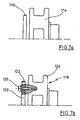
- FIGS. 7a and b show in detail views two differently designed planet carrier 114 and 116.
- the planet carrier 114 is integrally formed and has on its drive side a hub of a toothed coupling, which is provided with an external spline.
- the planet carrier 118 in FIG. 7b is formed in two pieces, wherein the hub of a toothed coupling with external splines is designed as a disc and is connected to the body 124 of the planet carrier 118 via screws 126.
Landscapes
- Engineering & Computer Science (AREA)
- General Engineering & Computer Science (AREA)
- Mechanical Engineering (AREA)
- Life Sciences & Earth Sciences (AREA)
- Sustainable Development (AREA)
- Sustainable Energy (AREA)
- Chemical & Material Sciences (AREA)
- Combustion & Propulsion (AREA)
- Retarders (AREA)
- Wind Motors (AREA)
- General Details Of Gearings (AREA)
Description
Die vorliegende Erfindung betrifft ein Getriebe für eine Windenergieanlage und insbesondere die Lagerung eines Planetenträgers in dem Getriebe einer Windenergieanlage.The present invention relates to a transmission for a wind energy plant and in particular the storage of a planet carrier in the transmission of a wind turbine.
Aus
Aus
Aus
Aus
Der Erfindung liegt die Aufgabe zugrunde, ein Getriebe für eine Windenergieanlage bereitzustellen, bei dem über den Planetenträger eine einfache Wellennabenverbindung ohne zusätzliche Bauteile realisiert werden kann.The invention has for its object to provide a transmission for a wind turbine, in which on the planet carrier a simple shaft hub connection can be realized without additional components.
Erfindungsgemäß wird die Aufgabe durch ein Getriebe mit den Merkmalen des Anspruchs 1 gelöst. Vorteilhafte Ausgestaltungen bilden den Gegenstand der Unteransprüche.According to the invention the object is achieved by a transmission with the features of claim 1. Advantageous embodiments form the subject of the dependent claims.
Die vorliegende Erfindung betrifft ein Getriebe für eine Windenergieanlage. Das Getriebe ist als ein ein- oder mehrstufiges Planetengetriebe ausgebildet, das einen Planetenträger besitzt. Der Planetenträger ist antriebsseitig mit einer Rotorwelle oder einer Rotornabe verbunden und über ein Lager gelagert, das innerhalb des Getriebegehäuses für den Planetenträger vorgesehen ist. Dabei kann der Planetenträger im Getriebegehäuse oder das Getriebegehäuse auf dem Planetenträger gelagert sein. Erfindungsgemäß ist das Lager abtriebsseitig der Planeten des Planetenträgers in dem Getriebegehäuse angeordnet. Die abtriebsseitige Position des Lagers für den Planetenträger bietet eine Reihe von besonderen Vorteilen. Bei einem bekannten Planetenträger, der an- und abtriebsseitig im Getriebegehäuse gelagert ist, muß das antriebsseitige Lager mit einem großen Innendurchmesser versehen sein, wodurch sich der Aufwand für das Lager erhöht. Alternativ kann auch eine Nabenverbindung eingesetzt werden, die auf einem geringen Durchmesser große Drehmomente übertragen kann. Solche Wellennabenverbindungen sind aufwendig und bauen groß. Im übrigen sind sie risikoreich in der Herstellung und Montage, was letztendlich auf die Kosten durchschlägt. Erfindungsgemäß ist die Verwendung eines kompakten Momentenlagers abtriebsseitig des Planetenträgers vorgesehen, das zur Aufnahme aller zwischen Planetenträger und Getriebegehäuse wirkenden Momente und Querkräfte dient. Hierdurch entsteht auch als besonderer Vorteil die Möglichkeit, antriebsseitig jede beliebige Rotorwellen- oder Rotornaben-Anbindung realisieren zu können. Eine mit dem erfindungsgemäß gelagerten Planetenträger verbundene Rotorwelle oder -nabe ist in an sich bekannter Weise außerhalb des Getriebes gelagert.The present invention relates to a transmission for a wind turbine. The transmission is designed as a single or multi-stage planetary gear, which has a planet carrier. The planet carrier is the drive side connected to a rotor shaft or a rotor hub and mounted on a bearing that within the Gear housing is provided for the planet carrier. In this case, the planet carrier may be mounted in the gear housing or the gear housing on the planet carrier. According to the invention, the bearing is arranged on the output side of the planet of the planet carrier in the transmission housing. The output side position of the bearing for the planet carrier offers a number of special advantages. In a known planet carrier, the input and output side in the transmission housing is stored, the drive-side bearing must be provided with a large inner diameter, which increases the cost of the camp. Alternatively, a hub connection can be used, which can transmit large torques on a small diameter. Such shaft hub connections are complex and build large. Moreover, they are risky in the production and assembly, which ultimately strikes the costs. According to the invention, the use of a compact torque bearing is provided on the output side of the planet carrier, which serves to receive all acting between the planet carrier and gear housing moments and transverse forces. As a result, it is also possible as a particular advantage to be able to realize any desired rotor shaft or rotor hub connection on the drive side. A rotor shaft or hub connected to the planet carrier mounted according to the invention is mounted in a manner known per se outside of the transmission.
Bevorzugt handelt es sich bei dem Planetengetriebe um ein mehrstufiges Planetengetriebe, wobei als der erfindungsgemäß gelagerte Planetenträger ein Planetenträger der ersten Stufe vorgesehen ist.Preferably, the planetary gear is a multi-stage planetary gear, wherein a planet carrier of the first stage is provided as the inventively mounted planet carrier.
Als Momentenlager kann bevorzugt ein eingestelltes Kegelrollenlagerpaar vorgesehen sein. Alternativ ist auch möglich, als Momentenlager ein dreireihiges Zylinderrollenlager vorzusehen. Grundsätzlich sind auch andere Ausführungsarten für das Lager denkbar, wenn das Lager ein Stützmoment bei gleichzeitiger axialer und radialer Führung bereitstellt.As a moment bearing can preferably be provided a set tapered roller bearing pair. Alternatively, it is also possible to provide a three-row cylindrical roller bearing as the moment bearing. In principle, other embodiments for the bearing are conceivable when the bearing provides a support torque with simultaneous axial and radial guidance.
In einer bevorzugten Ausgestaltung ist eine direkte Anbindung der Rotorwelle an den Planetenträger vorgesehen. Bei der direkten Anbindung ist zweckmäßigerweise ein Flansch formschlüssig an die Rotorwelle angebunden, mit dem der Planetenträger verschraubt ist. Alternativ hierzu kann eine Adapterscheibe zur direkten Anbindung der Rotornabe an den Planetenträger vorgesehen sein.In a preferred embodiment, a direct connection of the rotor shaft to the planet carrier is provided. In the direct connection, a flange is expediently connected in a form-fitting manner to the rotor shaft, to which the planet carrier is screwed. Alternatively, an adapter plate may be provided for direct connection of the rotor hub to the planet carrier.
In einer zweckmäßigen Ausgestaltung ist die Adapterscheibe mit dem Planetenträger verschraubt, wobei die mit der Adapterscheibe verbundene Rotornabe über ein Momentenlager auf einer Tragkonstruktion gelagert ist. Als Tragkonstruktion kann beispielsweise der Maschinenträger dienen, auf dem auch das Getriebe gelagert ist.In an expedient embodiment, the adapter disc is screwed to the planet carrier, wherein the rotor hub connected to the adapter disc is mounted on a support structure via a moment bearing. As a support structure, for example, serve the machine frame on which the transmission is mounted.
Bevorzugte Ausführungsbeispiele der erfindungsgemäßen Lagerung werden nachfolgend anhand von Ausführungsbeispielen näher erläutert. Es zeigt:
- Fig. 1
- das erfindungsgemäße Getriebe mit einer zweifach gelagerten Rotorwelle in einer Schnittansicht im Detail,
- Fig. 2
- ein erfindungsgemäß ausgeführtes Getriebe, das fest mit einem Maschinenträger oder einem Lagergehäuse einer Lagerung der Rotorwelle verschraubt ist in einer Schnittansicht im Detail,
- Fig. 3
- ein erfindungsgemäßes Getriebe, dessen Gehäuse mit einem Maschinenträger verschraubt ist, wobei die Lagerung der R otor- welle ebenfalls über ein Momentenlager erfolgt, in einer Schnitt- ansicht im Detail,
- Fig. 4
- ein erfindungsgemäßes Getriebe, bei dem die zweifachgelagerte Rotorwelle über einen Rotorwellenflansch mit dem Planetenträger verbunden ist, in einer Schnittansicht im Detail,
- Fig. 5
- ein erfindungsgemäßes Getriebe und eine Lagerung des Rotors über ein Momentenlager an einem Maschinenträger,
- Fig. 6
- die herkömmliche Lagerung des Planetenträgers in einem Getriebe für eine Windenergieanlage und
- Fign. 7a u. 7b zwei
- Detailansichten zu unterschiedlich ausgeführten Planeten- trägern.
- Fig. 1
- the transmission according to the invention with a rotor shaft mounted in duplicate in a sectional view in detail,
- Fig. 2
- a gearbox according to the invention, which is screwed tightly to a machine carrier or a bearing housing of a bearing of the rotor shaft in a sectional view in detail,
- Fig. 3
- a transmission according to the invention, the housing of which is screwed to a machine carrier, wherein the bearing of the rotor shaft likewise takes place via a moment bearing, in a sectional view in detail,
- Fig. 4
- a transmission according to the invention, in which the dual-bearing rotor shaft is connected to the planet carrier via a rotor shaft flange, in a sectional view in detail,
- Fig. 5
- an inventive transmission and a bearing of the rotor via a moment bearing on a machine carrier,
- Fig. 6
- the conventional storage of the planet carrier in a transmission for a wind turbine and
- FIGS. 7a and 7b two
- Detailed views of differently designed planet carriers.
Der Planetenträger 16 ist über ein Momentenlager 32 in dem Gehäuse 20 des Getriebes gelagert. Das Momentenlager 32 befindet sich auf der Abtriebsseite des Planetenträgers 16 und ist in dem dargestellten Ausführungsbeispiel als eingestelltes Kegelrollenlagerpaar ausgeführt.The
Die Besonderheit der erfindungsgemäßen Lagerung wird deutlich bei einem Vergleich mit der in
Wie in
Das in
Ein weiteres Ausführungsbeispiel für die erfindungsgemäße Lagerung des Planetenträgers ist in
Die vorgestellten Ausführungsbeispiele lassen sich systematisch in der folgenden Tabelle zusammenfassen:
Die erste Spalte betrifft die Rotorlagerung: Hierbei wird unterschieden zwischen einer Momentenlagerung für den Rotor und einer Zwei-Punkt-Lagerung. Bei der Zwei-Punkt-Lagerung sind noch die Fälle zu unterscheiden zwischen einer Zwei-Punkt-Lagerung mit einem einteiligen Gehäuse und einer Zwei-Punkt-Lagerung mit einem zweiteiligen Gehäuse.The first column concerns the rotor bearing: Here, a distinction is made between a moment bearing for the rotor and a two-point bearing. In two-point storage, there are still cases to distinguish between a two-point bearing with a one-piece housing and a two-point mounting with a two-part housing.
Die zweite Spalte bezeichnet die Verbindung zwischen Planetenträger und Rotorwelle/-nabe. Hier wird unterschieden zwischen einer Zahnkupplung, die als Steckverzahnung ausgeführt ist und einer kraft-/reibschlüssigen Verbindung, wie sie beispielsweise durch Verschrauben hergestellt werden kann. In der dritten Spalte dargestellt ist die Getriebeanbindung an den Maschinenträger. Hier wird unterschieden zwischen dem fest am Maschinenträger verschraubten Getriebe und dem über eine Drehmomentstütze und ein Entkopplungselement vorgesehenen Abstützung des Getriebes. In der Tabelle ist bereits deutlich zu erkennen, daß bei einer fest verschraubten Getriebeanbindung die Verbindung zwischen Planetenträger und Rotorwelle/-nabe über eine Zahnkupplung erfolgen muß. In der vierten Spalte dargestellt ist kurz das Lagerungsverhältnis vom Planetenträger zu Getriebegehäuse und die Figur, die eine entsprechende Ausgestaltung wiedergibt.The second column indicates the connection between planet carrier and rotor shaft / hub. Here is a distinction between a toothed coupling, which is designed as a spline and a frictional / frictional connection, as can be prepared for example by screwing. The third column shows the gearbox connection to the machine carrier. Here, a distinction is made between the fixed screwed to the machine frame gearbox and provided via a torque arm and a decoupling element support of the transmission. It can already be clearly seen in the table that, in the case of a fixedly bolted gear connection, the connection between planet carrier and rotor shaft / hub must take place via a toothed coupling. Shown in the fourth column is briefly the storage ratio of the planet carrier to gear housing and the figure, which reproduces a corresponding design.
Ein weiteres Ausführungsbeispiel ist in
Die Rotornabe 94 ist über ein zweites Momentenlager 106 als Rotorlager direkt am Maschinenträger 108 gelagert. Das Momentenlager 106 zur Lagerung der Rotorwelle ist über ein Dichtsystem 110 und 111 gegenüber äußeren Einflüssen abgedichtet. Das Momentenlager 106 befindet sich ungefähr im Bereich des Hohlrades 112 der ersten Planetenstufe. Die Rotornabe 94 und die Adapterscheibe 96 können als ein Teil ausgeführt sein.The
Claims (8)
- A transmission for a wind turbine, with a planet carrier (16, 52, 68, 86, 98), which is connected at the input side with a rotor shaft (10, 48, 78) or a rotor hub (94, 60) and is mounted via a bearing arranged in a transmission housing (20, 54, 74, 90, 105), the bearing (32, 58, 76, 88, 102) is arranged on the output side of the planet carrier (16, 52, 68, 86, 98) in the transmission housing (20, 54, 74, 90, 105), characterized in that a torque bearing (32, 58, 76, 88, 102) is provided as the bearing for the planet carrier.
- The transmission according to claim 1, characterized in that the planet carrier (16, 52, 68, 86, 98) is a planet carrier of the first stage in a multi-stage epicyclic gearbox.
- The transmission according to claim 1 or 2, characterized in that an adjusted pair of taper roller bearings is provided as the torque bearing (32, 58, 76, 88, 102).
- The transmission according to claim 1 or 2, characterized in that a three-row cylinder roller bearing is provided as the torque bearing (32, 58, 76, 88, 102).
- The transmission according to one of claims 1 to 4, characterized in that there is a direct connection of the rotor shaft to the planet carrier.
- The transmission according to one of claims 1 to 4, characterized in that there is a direct connection of the rotor hub to the planet carrier.
- The transmission according to one of claims 1 to 4, characterized in that an adapter disk is provided for the connection of the rotor hub to the planet carrier (16, 52, 68, 86, 98), wherein the adapter disk is connected with the planet carrier.
- The transmission according to one of claims 6 or 7, characterized in that the adapter disk or the rotor hub is mounted via a torque bearing as rotor bearing on a support (72).
Applications Claiming Priority (1)
| Application Number | Priority Date | Filing Date | Title |
|---|---|---|---|
| DE102007033806A DE102007033806B4 (en) | 2007-07-17 | 2007-07-17 | Transmission for a wind turbine |
Publications (3)
| Publication Number | Publication Date |
|---|---|
| EP2017474A2 EP2017474A2 (en) | 2009-01-21 |
| EP2017474A3 EP2017474A3 (en) | 2010-07-14 |
| EP2017474B1 true EP2017474B1 (en) | 2014-06-11 |
Family
ID=39929851
Family Applications (1)
| Application Number | Title | Priority Date | Filing Date |
|---|---|---|---|
| EP08002608.1A Active EP2017474B1 (en) | 2007-07-17 | 2008-02-13 | Transmission for a wind turbine |
Country Status (3)
| Country | Link |
|---|---|
| US (2) | US8409049B2 (en) |
| EP (1) | EP2017474B1 (en) |
| DE (1) | DE102007033806B4 (en) |
Families Citing this family (9)
| Publication number | Priority date | Publication date | Assignee | Title |
|---|---|---|---|---|
| DE102007033806B4 (en) | 2007-07-17 | 2011-03-17 | Nordex Energy Gmbh | Transmission for a wind turbine |
| US20110143880A1 (en) * | 2010-12-01 | 2011-06-16 | General Electric Company | Drivetrain for generator in wind turbine |
| GB201104455D0 (en) * | 2011-03-16 | 2011-04-27 | Romax Technology Ltd | Cover and sealing arrangements for a wind turbine gearbox |
| DK2938879T3 (en) * | 2012-08-21 | 2020-01-20 | Skf Ab | WIND TURBINE ROTOR AXLE DEVICE |
| EP2860336A3 (en) * | 2013-10-14 | 2018-01-03 | IMS Gear GmbH | Powered panel assembly for a motor vehicle |
| JP2016205603A (en) * | 2015-04-28 | 2016-12-08 | 株式会社ハーモニック・ドライブ・システムズ | Planetary gear reduction gear |
| EP3355942A4 (en) | 2015-10-01 | 2019-05-29 | Automatic Bar Controls, Inc. | Ultraviolet disinfecting device for food and beverage dispensers |
| CN105221340B (en) * | 2015-10-16 | 2017-12-05 | 明阳智慧能源集团股份公司 | Improved structure of compact wind generating set |
| DK202430601A1 (en) * | 2024-10-07 | 2025-10-02 | Vestas Wind Sys As | Transmission arrangement for a wind turbine |
Family Cites Families (15)
| Publication number | Priority date | Publication date | Assignee | Title |
|---|---|---|---|---|
| HU172495B (en) * | 1975-02-14 | 1978-09-28 | Magyar Vagon Es Gepgyar | Epicyclic wheel body drive which suitable for vehicle carriages |
| US4091688A (en) * | 1976-09-01 | 1978-05-30 | Dana Corporation | Easily assembled and disassembled planetary gear assembly |
| US4601592A (en) * | 1982-03-17 | 1986-07-22 | The Timken Company | Tapered roller bearing capable of sustained operation without lubricant replenishment |
| US4611505A (en) * | 1985-09-30 | 1986-09-16 | Caterpillar Inc. | Vehicular differential drive assembly and mounting means therefor |
| ATE209753T1 (en) | 1994-10-07 | 2001-12-15 | Windtec Anlagenerrichtungs Und | PLANETARY GEAR FOR WIND TURBINE |
| DE19916453A1 (en) | 1999-04-12 | 2000-10-19 | Flender A F & Co | Wind turbine |
| DE19916454A1 (en) * | 1999-04-12 | 2000-10-19 | Flender A F & Co | Gearbox for a wind turbine |
| DE10242707B3 (en) * | 2002-09-13 | 2004-04-15 | Aerodyn Engineering Gmbh | Wind turbine with concentric gear / generator arrangement |
| DE10318945B3 (en) * | 2003-04-26 | 2004-10-28 | Aerodyn Gmbh | Planetary gearing, for a wind energy generator, has a bearing structure where the load from the external rotor is minimized on the bearings and gear components to increase their life |
| JP4353735B2 (en) * | 2003-06-20 | 2009-10-28 | 株式会社ハーモニック・ドライブ・システムズ | Planetary gear set |
| DE10357026B3 (en) | 2003-12-03 | 2005-06-09 | Repower Systems Ag | Wind turbine |
| JP2005195097A (en) * | 2004-01-07 | 2005-07-21 | Ntn Corp | Cylindrical roller bearing and planetary gear using it |
| JP2006207623A (en) * | 2005-01-25 | 2006-08-10 | Ntn Corp | Vertical shaft supporting structure |
| DE102007033806B4 (en) | 2007-07-17 | 2011-03-17 | Nordex Energy Gmbh | Transmission for a wind turbine |
| CN100507307C (en) * | 2007-12-17 | 2009-07-01 | 南京高速齿轮制造有限公司 | Hybrid Drive Wind Turbine Speed-up Gearbox |
-
2007
- 2007-07-17 DE DE102007033806A patent/DE102007033806B4/en not_active Expired - Fee Related
-
2008
- 2008-02-13 EP EP08002608.1A patent/EP2017474B1/en active Active
- 2008-03-03 US US12/041,138 patent/US8409049B2/en not_active Expired - Fee Related
-
2013
- 2013-03-29 US US13/853,233 patent/US8753245B2/en active Active
Also Published As
| Publication number | Publication date |
|---|---|
| DE102007033806A1 (en) | 2009-01-22 |
| US20090023544A1 (en) | 2009-01-22 |
| US20130231209A1 (en) | 2013-09-05 |
| US8753245B2 (en) | 2014-06-17 |
| US8409049B2 (en) | 2013-04-02 |
| EP2017474A2 (en) | 2009-01-21 |
| DE102007033806B4 (en) | 2011-03-17 |
| EP2017474A3 (en) | 2010-07-14 |
Similar Documents
| Publication | Publication Date | Title |
|---|---|---|
| EP2017474B1 (en) | Transmission for a wind turbine | |
| EP2097641B1 (en) | Power-split wind power gearbox | |
| EP0792415B1 (en) | Planetary gear for wind turbines | |
| EP2737612B1 (en) | Drive unit mounted close to the wheel for a motor vehicle | |
| EP2795115B1 (en) | Blade bearing or nacelle bearing of a wind turbine | |
| DE102012217509A1 (en) | Gear unit with gear carrier | |
| DE102014205261A1 (en) | Swing motor of an active roll stabilizer for motor vehicles | |
| DE102009037005A1 (en) | Planetary gear for azimuth or pitch drives of wind energy plant, has drive- and output shafts, which are in effective connection over planetary stage, where bearing pins of planetary stage are formed with planetary carrier as single piece | |
| DE102008036217A1 (en) | Wind turbine with a rotor | |
| WO2014180688A1 (en) | Transmission and compressor system for a transmission | |
| WO2004077644A2 (en) | Spare part set for a gearmotor series | |
| DE102012221255A1 (en) | Bearing unit for rotor of wind power machine, has stator unit fastened with bearing unit at machine carrier of wind-power plant and rotor assembly, and rotor flange and stator flange fastened with rotor hub | |
| WO2014082781A1 (en) | Gearing unit having a plus gear set | |
| EP3767102B1 (en) | Drive train assembly | |
| DE202008010028U1 (en) | Arrangement for supporting a drive shaft of an automatic transmission | |
| DE102008036223A1 (en) | Bearing arrangement for wind-powered device to support shaft in housing of transmission or generator, has ready-to-fit bearing unit screwed with housing, where arrangement is closed by cover that is firmly screwed at common outer ring | |
| DE102013213662A1 (en) | Bearing arrangement for a planetary gear of a wind turbine | |
| DE102004004351A1 (en) | Planetary gearbox for a wind turbine | |
| EP2514076A1 (en) | Generator assembly for a wind power plant | |
| DE102012205946A1 (en) | Transmission device, particularly for wind turbine, has bearing unit performed as bearing unit that runs with planetary carrier, where planetary carrier and subsequent stage are supported against one another in axial manner | |
| DE102007005730A1 (en) | Differential with torque distribution for a motor vehicle | |
| DE102010040891A1 (en) | Drive device for window lifter installed at door of motor vehicle, has socket that is radially arranged along longitudinal axis between ball bearing and rotor shaft to connect ball bearing with rotor shaft | |
| DE102010043817A1 (en) | Planetary gear for e.g. wind turbine, has lubricant feed unit attached to lubricant channels of planetary gear stage for lubricant delivery and provided in region of drive side of planetary gear stage | |
| WO2023165769A1 (en) | Planetary gear assembly having a sun shaft mounted in/on the planet carrier, corresponding industrial transmission and use | |
| EP1913289B1 (en) | Differential without a housing |
Legal Events
| Date | Code | Title | Description |
|---|---|---|---|
| PUAI | Public reference made under article 153(3) epc to a published international application that has entered the european phase |
Free format text: ORIGINAL CODE: 0009012 |
|
| AK | Designated contracting states |
Kind code of ref document: A2 Designated state(s): AT BE BG CH CY CZ DE DK EE ES FI FR GB GR HR HU IE IS IT LI LT LU LV MC MT NL NO PL PT RO SE SI SK TR |
|
| AX | Request for extension of the european patent |
Extension state: AL BA MK RS |
|
| PUAL | Search report despatched |
Free format text: ORIGINAL CODE: 0009013 |
|
| AK | Designated contracting states |
Kind code of ref document: A3 Designated state(s): AT BE BG CH CY CZ DE DK EE ES FI FR GB GR HR HU IE IS IT LI LT LU LV MC MT NL NO PL PT RO SE SI SK TR |
|
| AX | Request for extension of the european patent |
Extension state: AL BA MK RS |
|
| RIC1 | Information provided on ipc code assigned before grant |
Ipc: F16H 57/02 20060101ALI20100607BHEP Ipc: F16H 57/08 20060101ALI20100607BHEP Ipc: F03D 11/02 20060101AFI20081113BHEP |
|
| 17P | Request for examination filed |
Effective date: 20110114 |
|
| AKX | Designation fees paid |
Designated state(s): AT BE BG CH CY CZ DE DK EE ES FI FR GB GR HR HU IE IS IT LI LT LU LV MC MT NL NO PL PT RO SE SI SK TR |
|
| REG | Reference to a national code |
Ref country code: DE Ref legal event code: R079 Ref document number: 502008011855 Country of ref document: DE Free format text: PREVIOUS MAIN CLASS: F03D0011020000 Ipc: F01D0011000000 |
|
| RIC1 | Information provided on ipc code assigned before grant |
Ipc: F16H 57/021 20120101ALI20131004BHEP Ipc: F01D 11/00 20060101AFI20131004BHEP Ipc: F03D 11/02 20060101ALI20131004BHEP Ipc: F03D 11/00 20060101ALI20131004BHEP Ipc: F16H 57/08 20060101ALI20131004BHEP |
|
| GRAP | Despatch of communication of intention to grant a patent |
Free format text: ORIGINAL CODE: EPIDOSNIGR1 |
|
| INTG | Intention to grant announced |
Effective date: 20131206 |
|
| GRAS | Grant fee paid |
Free format text: ORIGINAL CODE: EPIDOSNIGR3 |
|
| GRAA | (expected) grant |
Free format text: ORIGINAL CODE: 0009210 |
|
| RAP1 | Party data changed (applicant data changed or rights of an application transferred) |
Owner name: NORDEX ENERGY GMBH |
|
| AK | Designated contracting states |
Kind code of ref document: B1 Designated state(s): AT BE BG CH CY CZ DE DK EE ES FI FR GB GR HR HU IE IS IT LI LT LU LV MC MT NL NO PL PT RO SE SI SK TR |
|
| REG | Reference to a national code |
Ref country code: GB Ref legal event code: FG4D Free format text: NOT ENGLISH |
|
| REG | Reference to a national code |
Ref country code: CH Ref legal event code: EP |
|
| REG | Reference to a national code |
Ref country code: IE Ref legal event code: FG4D Free format text: LANGUAGE OF EP DOCUMENT: GERMAN |
|
| REG | Reference to a national code |
Ref country code: AT Ref legal event code: REF Ref document number: 672370 Country of ref document: AT Kind code of ref document: T Effective date: 20140715 |
|
| REG | Reference to a national code |
Ref country code: DE Ref legal event code: R096 Ref document number: 502008011855 Country of ref document: DE Effective date: 20140724 |
|
| REG | Reference to a national code |
Ref country code: SE Ref legal event code: TRGR |
|
| PG25 | Lapsed in a contracting state [announced via postgrant information from national office to epo] |
Ref country code: GR Free format text: LAPSE BECAUSE OF FAILURE TO SUBMIT A TRANSLATION OF THE DESCRIPTION OR TO PAY THE FEE WITHIN THE PRESCRIBED TIME-LIMIT Effective date: 20140912 Ref country code: FI Free format text: LAPSE BECAUSE OF FAILURE TO SUBMIT A TRANSLATION OF THE DESCRIPTION OR TO PAY THE FEE WITHIN THE PRESCRIBED TIME-LIMIT Effective date: 20140611 Ref country code: NO Free format text: LAPSE BECAUSE OF FAILURE TO SUBMIT A TRANSLATION OF THE DESCRIPTION OR TO PAY THE FEE WITHIN THE PRESCRIBED TIME-LIMIT Effective date: 20140911 Ref country code: LT Free format text: LAPSE BECAUSE OF FAILURE TO SUBMIT A TRANSLATION OF THE DESCRIPTION OR TO PAY THE FEE WITHIN THE PRESCRIBED TIME-LIMIT Effective date: 20140611 |
|
| REG | Reference to a national code |
Ref country code: NL Ref legal event code: VDEP Effective date: 20140611 |
|
| REG | Reference to a national code |
Ref country code: LT Ref legal event code: MG4D |
|
| PG25 | Lapsed in a contracting state [announced via postgrant information from national office to epo] |
Ref country code: LV Free format text: LAPSE BECAUSE OF FAILURE TO SUBMIT A TRANSLATION OF THE DESCRIPTION OR TO PAY THE FEE WITHIN THE PRESCRIBED TIME-LIMIT Effective date: 20140611 Ref country code: HR Free format text: LAPSE BECAUSE OF FAILURE TO SUBMIT A TRANSLATION OF THE DESCRIPTION OR TO PAY THE FEE WITHIN THE PRESCRIBED TIME-LIMIT Effective date: 20140611 |
|
| PG25 | Lapsed in a contracting state [announced via postgrant information from national office to epo] |
Ref country code: ES Free format text: LAPSE BECAUSE OF FAILURE TO SUBMIT A TRANSLATION OF THE DESCRIPTION OR TO PAY THE FEE WITHIN THE PRESCRIBED TIME-LIMIT Effective date: 20140611 Ref country code: SK Free format text: LAPSE BECAUSE OF FAILURE TO SUBMIT A TRANSLATION OF THE DESCRIPTION OR TO PAY THE FEE WITHIN THE PRESCRIBED TIME-LIMIT Effective date: 20140611 Ref country code: PT Free format text: LAPSE BECAUSE OF FAILURE TO SUBMIT A TRANSLATION OF THE DESCRIPTION OR TO PAY THE FEE WITHIN THE PRESCRIBED TIME-LIMIT Effective date: 20141013 Ref country code: CZ Free format text: LAPSE BECAUSE OF FAILURE TO SUBMIT A TRANSLATION OF THE DESCRIPTION OR TO PAY THE FEE WITHIN THE PRESCRIBED TIME-LIMIT Effective date: 20140611 Ref country code: RO Free format text: LAPSE BECAUSE OF FAILURE TO SUBMIT A TRANSLATION OF THE DESCRIPTION OR TO PAY THE FEE WITHIN THE PRESCRIBED TIME-LIMIT Effective date: 20140611 Ref country code: EE Free format text: LAPSE BECAUSE OF FAILURE TO SUBMIT A TRANSLATION OF THE DESCRIPTION OR TO PAY THE FEE WITHIN THE PRESCRIBED TIME-LIMIT Effective date: 20140611 |
|
| PG25 | Lapsed in a contracting state [announced via postgrant information from national office to epo] |
Ref country code: IS Free format text: LAPSE BECAUSE OF FAILURE TO SUBMIT A TRANSLATION OF THE DESCRIPTION OR TO PAY THE FEE WITHIN THE PRESCRIBED TIME-LIMIT Effective date: 20141011 Ref country code: NL Free format text: LAPSE BECAUSE OF FAILURE TO SUBMIT A TRANSLATION OF THE DESCRIPTION OR TO PAY THE FEE WITHIN THE PRESCRIBED TIME-LIMIT Effective date: 20140611 Ref country code: PL Free format text: LAPSE BECAUSE OF FAILURE TO SUBMIT A TRANSLATION OF THE DESCRIPTION OR TO PAY THE FEE WITHIN THE PRESCRIBED TIME-LIMIT Effective date: 20140611 |
|
| REG | Reference to a national code |
Ref country code: DE Ref legal event code: R097 Ref document number: 502008011855 Country of ref document: DE |
|
| PLBE | No opposition filed within time limit |
Free format text: ORIGINAL CODE: 0009261 |
|
| STAA | Information on the status of an ep patent application or granted ep patent |
Free format text: STATUS: NO OPPOSITION FILED WITHIN TIME LIMIT |
|
| PG25 | Lapsed in a contracting state [announced via postgrant information from national office to epo] |
Ref country code: IT Free format text: LAPSE BECAUSE OF FAILURE TO SUBMIT A TRANSLATION OF THE DESCRIPTION OR TO PAY THE FEE WITHIN THE PRESCRIBED TIME-LIMIT Effective date: 20140611 Ref country code: DK Free format text: LAPSE BECAUSE OF FAILURE TO SUBMIT A TRANSLATION OF THE DESCRIPTION OR TO PAY THE FEE WITHIN THE PRESCRIBED TIME-LIMIT Effective date: 20140611 |
|
| 26N | No opposition filed |
Effective date: 20150312 |
|
| REG | Reference to a national code |
Ref country code: DE Ref legal event code: R097 Ref document number: 502008011855 Country of ref document: DE Effective date: 20150312 |
|
| PG25 | Lapsed in a contracting state [announced via postgrant information from national office to epo] |
Ref country code: BE Free format text: LAPSE BECAUSE OF NON-PAYMENT OF DUE FEES Effective date: 20150228 |
|
| PG25 | Lapsed in a contracting state [announced via postgrant information from national office to epo] |
Ref country code: SI Free format text: LAPSE BECAUSE OF FAILURE TO SUBMIT A TRANSLATION OF THE DESCRIPTION OR TO PAY THE FEE WITHIN THE PRESCRIBED TIME-LIMIT Effective date: 20140611 |
|
| PG25 | Lapsed in a contracting state [announced via postgrant information from national office to epo] |
Ref country code: LU Free format text: LAPSE BECAUSE OF FAILURE TO SUBMIT A TRANSLATION OF THE DESCRIPTION OR TO PAY THE FEE WITHIN THE PRESCRIBED TIME-LIMIT Effective date: 20150213 |
|
| REG | Reference to a national code |
Ref country code: CH Ref legal event code: PL |
|
| PG25 | Lapsed in a contracting state [announced via postgrant information from national office to epo] |
Ref country code: MC Free format text: LAPSE BECAUSE OF FAILURE TO SUBMIT A TRANSLATION OF THE DESCRIPTION OR TO PAY THE FEE WITHIN THE PRESCRIBED TIME-LIMIT Effective date: 20140611 Ref country code: LI Free format text: LAPSE BECAUSE OF NON-PAYMENT OF DUE FEES Effective date: 20150228 Ref country code: CH Free format text: LAPSE BECAUSE OF NON-PAYMENT OF DUE FEES Effective date: 20150228 |
|
| REG | Reference to a national code |
Ref country code: IE Ref legal event code: MM4A |
|
| PG25 | Lapsed in a contracting state [announced via postgrant information from national office to epo] |
Ref country code: IE Free format text: LAPSE BECAUSE OF NON-PAYMENT OF DUE FEES Effective date: 20150213 |
|
| REG | Reference to a national code |
Ref country code: FR Ref legal event code: PLFP Year of fee payment: 9 |
|
| REG | Reference to a national code |
Ref country code: AT Ref legal event code: MM01 Ref document number: 672370 Country of ref document: AT Kind code of ref document: T Effective date: 20150213 |
|
| PG25 | Lapsed in a contracting state [announced via postgrant information from national office to epo] |
Ref country code: AT Free format text: LAPSE BECAUSE OF NON-PAYMENT OF DUE FEES Effective date: 20150213 |
|
| PG25 | Lapsed in a contracting state [announced via postgrant information from national office to epo] |
Ref country code: MT Free format text: LAPSE BECAUSE OF FAILURE TO SUBMIT A TRANSLATION OF THE DESCRIPTION OR TO PAY THE FEE WITHIN THE PRESCRIBED TIME-LIMIT Effective date: 20140611 |
|
| REG | Reference to a national code |
Ref country code: FR Ref legal event code: PLFP Year of fee payment: 10 |
|
| PGFP | Annual fee paid to national office [announced via postgrant information from national office to epo] |
Ref country code: FR Payment date: 20170220 Year of fee payment: 10 |
|
| PG25 | Lapsed in a contracting state [announced via postgrant information from national office to epo] |
Ref country code: BG Free format text: LAPSE BECAUSE OF FAILURE TO SUBMIT A TRANSLATION OF THE DESCRIPTION OR TO PAY THE FEE WITHIN THE PRESCRIBED TIME-LIMIT Effective date: 20140611 Ref country code: HU Free format text: LAPSE BECAUSE OF FAILURE TO SUBMIT A TRANSLATION OF THE DESCRIPTION OR TO PAY THE FEE WITHIN THE PRESCRIBED TIME-LIMIT; INVALID AB INITIO Effective date: 20080213 |
|
| PGFP | Annual fee paid to national office [announced via postgrant information from national office to epo] |
Ref country code: GB Payment date: 20170221 Year of fee payment: 10 |
|
| PG25 | Lapsed in a contracting state [announced via postgrant information from national office to epo] |
Ref country code: CY Free format text: LAPSE BECAUSE OF FAILURE TO SUBMIT A TRANSLATION OF THE DESCRIPTION OR TO PAY THE FEE WITHIN THE PRESCRIBED TIME-LIMIT Effective date: 20140611 |
|
| PG25 | Lapsed in a contracting state [announced via postgrant information from national office to epo] |
Ref country code: TR Free format text: LAPSE BECAUSE OF FAILURE TO SUBMIT A TRANSLATION OF THE DESCRIPTION OR TO PAY THE FEE WITHIN THE PRESCRIBED TIME-LIMIT Effective date: 20140611 |
|
| GBPC | Gb: european patent ceased through non-payment of renewal fee |
Effective date: 20180213 |
|
| REG | Reference to a national code |
Ref country code: FR Ref legal event code: ST Effective date: 20181031 |
|
| PG25 | Lapsed in a contracting state [announced via postgrant information from national office to epo] |
Ref country code: GB Free format text: LAPSE BECAUSE OF NON-PAYMENT OF DUE FEES Effective date: 20180213 Ref country code: FR Free format text: LAPSE BECAUSE OF NON-PAYMENT OF DUE FEES Effective date: 20180228 |
|
| PGFP | Annual fee paid to national office [announced via postgrant information from national office to epo] |
Ref country code: SE Payment date: 20190221 Year of fee payment: 12 |
|
| REG | Reference to a national code |
Ref country code: SE Ref legal event code: EUG |
|
| PG25 | Lapsed in a contracting state [announced via postgrant information from national office to epo] |
Ref country code: SE Free format text: LAPSE BECAUSE OF NON-PAYMENT OF DUE FEES Effective date: 20200214 |
|
| REG | Reference to a national code |
Ref country code: DE Ref legal event code: R082 Ref document number: 502008011855 Country of ref document: DE Representative=s name: HAUCK PATENTANWALTSPARTNERSCHAFT MBB, DE Ref country code: DE Ref legal event code: R081 Ref document number: 502008011855 Country of ref document: DE Owner name: NORDEX ENERGY SE & CO. KG, DE Free format text: FORMER OWNER: NORDEX ENERGY GMBH, 22419 HAMBURG, DE |
|
| P01 | Opt-out of the competence of the unified patent court (upc) registered |
Effective date: 20230602 |
|
| PGFP | Annual fee paid to national office [announced via postgrant information from national office to epo] |
Ref country code: DE Payment date: 20250218 Year of fee payment: 18 |