EP2017013B1 - Slot coating gun and method of extruding a foamable melted material in a wide band - Google Patents
Slot coating gun and method of extruding a foamable melted material in a wide band Download PDFInfo
- Publication number
- EP2017013B1 EP2017013B1 EP08160453A EP08160453A EP2017013B1 EP 2017013 B1 EP2017013 B1 EP 2017013B1 EP 08160453 A EP08160453 A EP 08160453A EP 08160453 A EP08160453 A EP 08160453A EP 2017013 B1 EP2017013 B1 EP 2017013B1
- Authority
- EP
- European Patent Office
- Prior art keywords
- melted material
- slot
- foamable melted
- passage
- lateral distribution
- Prior art date
- Legal status (The legal status is an assumption and is not a legal conclusion. Google has not performed a legal analysis and makes no representation as to the accuracy of the status listed.)
- Not-in-force
Links
- 239000000463 material Substances 0.000 title claims description 155
- 239000011248 coating agent Substances 0.000 title claims description 28
- 238000000576 coating method Methods 0.000 title claims description 28
- 238000000034 method Methods 0.000 title claims description 9
- 238000009826 distribution Methods 0.000 claims description 125
- 239000006260 foam Substances 0.000 claims description 73
- 239000000758 substrate Substances 0.000 claims description 36
- 230000000712 assembly Effects 0.000 claims description 31
- 238000000429 assembly Methods 0.000 claims description 31
- 238000007599 discharging Methods 0.000 claims description 3
- 239000010410 layer Substances 0.000 description 37
- 238000010586 diagram Methods 0.000 description 18
- 239000007789 gas Substances 0.000 description 16
- 238000005187 foaming Methods 0.000 description 10
- 239000012943 hotmelt Substances 0.000 description 7
- 239000000126 substance Substances 0.000 description 6
- CURLTUGMZLYLDI-UHFFFAOYSA-N Carbon dioxide Chemical compound O=C=O CURLTUGMZLYLDI-UHFFFAOYSA-N 0.000 description 4
- 230000002028 premature Effects 0.000 description 4
- 239000000853 adhesive Substances 0.000 description 3
- 230000001070 adhesive effect Effects 0.000 description 3
- 238000005096 rolling process Methods 0.000 description 3
- IJGRMHOSHXDMSA-UHFFFAOYSA-N Atomic nitrogen Chemical compound N#N IJGRMHOSHXDMSA-UHFFFAOYSA-N 0.000 description 2
- 238000004026 adhesive bonding Methods 0.000 description 2
- 239000012790 adhesive layer Substances 0.000 description 2
- 239000001569 carbon dioxide Substances 0.000 description 2
- 229910002092 carbon dioxide Inorganic materials 0.000 description 2
- 230000008859 change Effects 0.000 description 2
- 230000008018 melting Effects 0.000 description 2
- 238000002844 melting Methods 0.000 description 2
- 230000004048 modification Effects 0.000 description 2
- 238000012986 modification Methods 0.000 description 2
- 229920000098 polyolefin Polymers 0.000 description 2
- 239000007787 solid Substances 0.000 description 2
- 238000011144 upstream manufacturing Methods 0.000 description 2
- 239000004952 Polyamide Substances 0.000 description 1
- 239000002390 adhesive tape Substances 0.000 description 1
- 239000003570 air Substances 0.000 description 1
- 230000015572 biosynthetic process Effects 0.000 description 1
- 230000005587 bubbling Effects 0.000 description 1
- 239000000470 constituent Substances 0.000 description 1
- 230000007423 decrease Effects 0.000 description 1
- 229910001873 dinitrogen Inorganic materials 0.000 description 1
- 229920001971 elastomer Polymers 0.000 description 1
- 239000003292 glue Substances 0.000 description 1
- 239000011261 inert gas Substances 0.000 description 1
- 239000007788 liquid Substances 0.000 description 1
- 238000004519 manufacturing process Methods 0.000 description 1
- 239000000203 mixture Substances 0.000 description 1
- JCXJVPUVTGWSNB-UHFFFAOYSA-N nitrogen dioxide Inorganic materials O=[N]=O JCXJVPUVTGWSNB-UHFFFAOYSA-N 0.000 description 1
- 238000009828 non-uniform distribution Methods 0.000 description 1
- 230000001151 other effect Effects 0.000 description 1
- 229920002647 polyamide Polymers 0.000 description 1
- 229920000728 polyester Polymers 0.000 description 1
- 239000011148 porous material Substances 0.000 description 1
- 230000008569 process Effects 0.000 description 1
- 230000009467 reduction Effects 0.000 description 1
- 229920006395 saturated elastomer Polymers 0.000 description 1
- 239000003566 sealing material Substances 0.000 description 1
- 238000004904 shortening Methods 0.000 description 1
- 238000003892 spreading Methods 0.000 description 1
- 230000007480 spreading Effects 0.000 description 1
Images


Classifications
-
- B—PERFORMING OPERATIONS; TRANSPORTING
- B05—SPRAYING OR ATOMISING IN GENERAL; APPLYING FLUENT MATERIALS TO SURFACES, IN GENERAL
- B05C—APPARATUS FOR APPLYING FLUENT MATERIALS TO SURFACES, IN GENERAL
- B05C5/00—Apparatus in which liquid or other fluent material is projected, poured or allowed to flow on to the surface of the work
- B05C5/02—Apparatus in which liquid or other fluent material is projected, poured or allowed to flow on to the surface of the work the liquid or other fluent material being discharged through an outlet orifice by pressure, e.g. from an outlet device in contact or almost in contact, with the work
- B05C5/0254—Coating heads with slot-shaped outlet
- B05C5/0258—Coating heads with slot-shaped outlet flow controlled, e.g. by a valve
-
- B—PERFORMING OPERATIONS; TRANSPORTING
- B01—PHYSICAL OR CHEMICAL PROCESSES OR APPARATUS IN GENERAL
- B01F—MIXING, e.g. DISSOLVING, EMULSIFYING OR DISPERSING
- B01F23/00—Mixing according to the phases to be mixed, e.g. dispersing or emulsifying
- B01F23/20—Mixing gases with liquids
- B01F23/29—Mixing systems, i.e. flow charts or diagrams
- B01F23/291—Mixing systems, i.e. flow charts or diagrams for obtaining foams or aerosols
-
- B—PERFORMING OPERATIONS; TRANSPORTING
- B05—SPRAYING OR ATOMISING IN GENERAL; APPLYING FLUENT MATERIALS TO SURFACES, IN GENERAL
- B05C—APPARATUS FOR APPLYING FLUENT MATERIALS TO SURFACES, IN GENERAL
- B05C5/00—Apparatus in which liquid or other fluent material is projected, poured or allowed to flow on to the surface of the work
- B05C5/02—Apparatus in which liquid or other fluent material is projected, poured or allowed to flow on to the surface of the work the liquid or other fluent material being discharged through an outlet orifice by pressure, e.g. from an outlet device in contact or almost in contact, with the work
- B05C5/027—Coating heads with several outlets, e.g. aligned transversally to the moving direction of a web to be coated
- B05C5/0275—Coating heads with several outlets, e.g. aligned transversally to the moving direction of a web to be coated flow controlled, e.g. by a valve
- B05C5/0279—Coating heads with several outlets, e.g. aligned transversally to the moving direction of a web to be coated flow controlled, e.g. by a valve independently, e.g. individually, flow controlled
-
- B—PERFORMING OPERATIONS; TRANSPORTING
- B29—WORKING OF PLASTICS; WORKING OF SUBSTANCES IN A PLASTIC STATE IN GENERAL
- B29C—SHAPING OR JOINING OF PLASTICS; SHAPING OF MATERIAL IN A PLASTIC STATE, NOT OTHERWISE PROVIDED FOR; AFTER-TREATMENT OF THE SHAPED PRODUCTS, e.g. REPAIRING
- B29C44/00—Shaping by internal pressure generated in the material, e.g. swelling or foaming ; Producing porous or cellular expanded plastics articles
- B29C44/34—Auxiliary operations
- B29C44/36—Feeding the material to be shaped
- B29C44/46—Feeding the material to be shaped into an open space or onto moving surfaces, i.e. to make articles of indefinite length
- B29C44/461—Feeding the material to be shaped into an open space or onto moving surfaces, i.e. to make articles of indefinite length dispensing apparatus, e.g. dispensing foaming resin over the whole width of the moving surface
-
- B—PERFORMING OPERATIONS; TRANSPORTING
- B05—SPRAYING OR ATOMISING IN GENERAL; APPLYING FLUENT MATERIALS TO SURFACES, IN GENERAL
- B05C—APPARATUS FOR APPLYING FLUENT MATERIALS TO SURFACES, IN GENERAL
- B05C5/00—Apparatus in which liquid or other fluent material is projected, poured or allowed to flow on to the surface of the work
- B05C5/02—Apparatus in which liquid or other fluent material is projected, poured or allowed to flow on to the surface of the work the liquid or other fluent material being discharged through an outlet orifice by pressure, e.g. from an outlet device in contact or almost in contact, with the work
- B05C5/027—Coating heads with several outlets, e.g. aligned transversally to the moving direction of a web to be coated
Definitions
- the present invention pertains to a slot coating gun and a method of extruding a foamable melted material in a wide band.
- foam melt applicators for coating a foamable melted material have been known (for example, see Patent Document 1).
- a foam melt applicator is a device which mechanically mixes an inert gas into melted hot melt and discharges a bubbly hot melt. Coating a foamable melted material can reduce running costs and lengthen open time before clamping. Other effects include shortening the setting time after clamping, making it easier to thinly spread an adhesive layer after clamping, increased adhesion strength with porous materials, increased filling efficiency on a bonded item that has a rough surface, formation of a coating film with elasticity, etc. Therefore foamable melted materials are widely used.
- a slot nozzle which can keep a foamable melted material at a pressure higher than the critical pressure at which the foamable melted material does not foam until the foamable melted material reaches the outlet part of the slot (for example, see Patent Document 3).
- This slot nozzle is provided with a converging slot part in which the thickness of the slot is gradually reduced from the wide slot part, where the slot is thick, to the outlet slot part, where the slot is thin.
- a foamable melted material foams after being extruded from a slotted discharge device and forms a foam layer on the substrate.
- a bubbling sound can be heard from the slotted discharge device, and in this sort of case, holes occur in the foam layer formed on the substrate.
- gases dissolved in the foamable melted material started to foam inside the slotted discharge device and premature foaming occurred.
- premature foaming occurs, the texture of the foam layer becomes unallowably rough, and holes are formed in the foam layer.
- a foam layer that has holes reduces the quality of the product. Therefore, one must keep the pressure inside a slotted discharge device at a pressure higher than the critical pressure at which the foamable melted material starts to foam so that the foamable melted material does not foam inside the slotted discharge device.
- a foamable melted material must be uniformly distributed across the entire width of the slot. Therefore, it is necessary to disperse the foamable melted material widely and thinly in the interior of a slotted discharge device. If the flow speed of the foamable melted material inside a slotted discharge device is nonuniform, or if the pressure distribution of the foamable melted material is biased, the diameter of bubbles inside the foam layer coated on the substrate becomes nonuniform.
- FIG. 15 is an explanatory diagram schematically showing the flow of a foamable melted material in the interior of a conventional slot nozzle assembly and bubbles in the foam layer coated on a substrate.
- a slot nozzle assembly 100 is attached to a control module 118 ( FIG. 17 ).
- the slot nozzle assembly 100 is provided with five vertical passages 102.
- the vertical passages 102 respectively communicate with valve assemblies 120 ( FIG. 17 ) provided in the control module 118 ( FIG. 17 ).
- the five vertical passages 102 communicate with a single lateral distribution flow route 104 provided in the slot nozzle assembly 100.
- the lateral distribution flow route 104 communicates with a slender slot 106 which extends in the longitudinal direction of the slot nozzle assembly 100.
- the foamable melted material passes through the vertical passage 102 as indicated by arrow A and flows to the lateral distribution flow route 104.
- the foamable melted material is laterally dispersed along the lateral distribution flow route 104 as indicated by arrows B, C, D, and E, passes through the slot 106, is extruded on a substrate 108, and forms a foam layer 110.
- the thickness of the arrows A, B, C, D, and E represents the flow amount of foamable melted material.
- the flow amount of foamable melted material flowing from the lateral distribution flow route 104 to the slot 106 is large directly under the vertical passage 102 as indicated by arrow B, and the flow amount diminishes with distance from the vertical passage 102 as indicated by the thicknesses of arrows C, D, and E. Pressure also diminishes with the reduction in flow amount.
- FIG. 15 shows a cross-section view of the foam layer 110 taken along the direction perpendicular to the substrate 108's transport direction.
- the foam layer 110 includes a thick-layer portion 110a formed directly under the vertical passage 102 and a thin-layer portion 110b formed between adjacent vertical passages 102.
- the diameter of a bubble 112a formed inside the thick-layer portion 110a is small, and the diameter of a bubble 112b formed inside the thin-layer portion 110b is large.
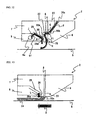
- FIG. 16 is an explanatory diagram showing foam accumulated on the surface of the rear nozzle block of a conventional slot nozzle assembly.
- the substrate 108 is transported in the direction indicated by arrow X.
- the slot nozzle assembly 100 consists of a front nozzle block 114 and a rear nozzle block 116; the slot 106 is formed between the front nozzle block 114 and the rear nozzle block 116.
- the front nozzle block 114 is positioned at the upstream side of the substrate 108's transport direction X.
- the rear nozzle block 116 is positioned at the downstream side of the substrate 108's transport direction X.
- the foamable melted material extruded from the outlet 106a of the slot 106 foams and coats the substrate 108 and forms the foam layer 110 at the downstream side of the transport direction X.
- part 110c of the foam coated on the substrate 108 adheres to the surface 116a of the rear nozzle block 116.
- the volume of the foam may sometimes become very large and it adheres to the surface 116a of the rear nozzle block 116.
- Foam part 110c gradually accumulates, and deteriorates. Subsequently, the foam part 110c drips on the foam layer 110. In particular, large drips of foam are visible on the foam layer, so the product is soiled and the quality of the product is reduced.
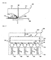
- FIG. 17 is an explanatory drawing showing a foamable melted material distribution manifold 210 of a conventional slot coating gun 200.
- the slot coating gun 200 consists of a slot nozzle assembly 100, control module 118, and gun body 122.
- the control module 118 is provided with five valve assemblies 120, and these valve assemblies 120 respectively communicate with the vertical passages 102 provided in the slot nozzle assembly 100.
- a lateral distributional passage 130 is provided in the control module 118, and the lateral distribution passage 130 communicates with the five valve assemblies 120.
- a lateral distribution passage 132 is provided in the gun body 122.
- the two ends of the lateral distribution passage 130 of the control module 118 communicate with the two ends of the lateral distribution passage 132 of the gun body 122 via passage 134 and passage 136 respectively.
- a passage 138 is provided in the gun body 122 so that the lateral distribution passage 132 communicates with a foam station (not shown in the drawing).
- the foamable melted material distribution manifold 210 is constituted by the lateral distribution passage 130, lateral distribution passage 132, passage 134, and passage 136.
- Foamable melted material is sent from a foam station (not shown in the drawing) through the passage 138 to the foamable melted material distribution manifold 210.
- the passage 138 is connected to essentially the center of the lateral distribution passage 132 of the gun body 122.
- Foamable melted material from the passage 138 is distributed left and right from essentially the center of the lateral distribution passage 132, and flows to the passage 134 and passage 136 respectively at both ends of the lateral distribution passage 132.
- Foamable melted material from the passage 134 and passage 136 enters both ends of the lateral distribution passage 130 of the control module 118, and flows toward the center of the lateral distribution passage 130.
- the foamable melted material is supplied to the five valve assemblies 120, which communicate with the lateral distribution passage 130.
- the pressure and flow amount of the foamable melted material supplied to the valve assemblies 120 near both ends of the lateral distribution passage 130 become larger than the pressure and flow amount of the foamable melted material supplied to the valve assemblies 120 at the center of the lateral distribution passage 130. Therefore, the pressure and flow amount of the foamable melted material supplied from the valve assemblies 120 to the vertical passages 102 of the slot nozzle assembly 100 gradually become smaller from both ends of the slot nozzle assembly 100 towards its center, as indicated by the thickness of arrows P, Q, and R in FIG. 17 .
- the present invention is a slot coating gun with the features of claim 1. That is, a slot coating gun (1) for extruding a foamable melted material in a wide band was provided with an inlet passage (34) for receiving foamable melted material, a plurality of valve assemblies (28), a foamable melted material distribution manifold (27) communicating with the inlet passage and the plurality of valve assemblies, a slot nozzle assembly having a plurality of foamable melted material passages (20) respectively communicating with the plurality of valve assemblies, lateral distribution flow routes (21, 22) communicating with the plurality of foamable melted material passages, a restriction member (8) disposed inside the lateral distribution flow routes, a slot (23) for discharging foamable melted material, and a converging portion (22a) which communicates with the lateral distribution flow routes and the slot, and whose cross-section area gradually becomes smaller toward the slot.
- the foamable melted material distribution manifold comprises a first lateral distribution passage (29) communicating with the plurality of valve assemblies, a second lateral distribution passage (30) communicating with the inlet passage, two end passages (31, 32) respectively connecting both ends of the first lateral distribution passage and both ends of the second lateral distribution passage, and a plurality of traverse passages (33) connecting the first lateral distribution passage and the second lateral distribution passage at points respectively between adjacent valve assemblies.
- a hot air outlet (26a) for discharging hot air may be provided at the downstream side of the slot in the transport direction of a substrate on which a foaming melting material is coated. As a result, the foam of the extruded foamable melted material is separated from the nozzle surface by the hot air. That is, it makes it easy to peel off foam adhered to the nozzle.
- the present invention is a method of extruding a foamable melted material in a wide band, in accordance with claim 6.
- Disclosed is also a method of extruding a foamable melted material in a wide band, and included a step of passing a foamable melted material from the plurality of foamable melted material passages (20) to the first lateral distribution flow route (21), a step of restricting the flow of the foamable melted material from the first lateral distribution flow route to the second lateral distribution flow route (22) using a dispersing plate (8) in order to keep the pressure of the foamable melted material inside the first lateral distribution flow route at critical pressure or higher, a step of restricting the flow of the foamable melted material from the second lateral distribution flow route to the slot (23) using the thickness (T) of the slot in order to keep the pressure of the foamable melted material inside the second lateral distribution flow route at critical pressure or higher, and a step of extruding the foamable melted material from the slot to a substrate in
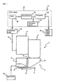
- FIG. 1 is a diagram showing one embodiment in accordance with the present invention, including a slot coating gun and a system for supplying a foamable melted material.
- the wide slot coating gun 1 consists of the slot nozzle assembly 2, control module 3, and gun body 4.
- a wide flat substrate 5 is transported in the direction indicated by arrow X below the slot nozzle assembly 2, either touching or not touching the slot nozzle assembly 2.
- the slot nozzle assembly 2 consists of the front nozzle block 6, rear nozzle block 7, shim plate 8 disposed between the front nozzle block 6 and rear nozzle block 7, and an air block 9 attached to the rear nozzle block 7.
- the front nozzle block 6 is positioned at the upstream side of the substrate 5's transport direction X.
- the rear nozzle block 7 is positioned at the downstream side of the substrate 5's transport direction X.
- the air block 9 is supplied with hot air from a hot air source 10.
- the gun body 4 is supplied with a foamable melted material from a foamable melted material supply system 11.
- the gun body 4 is provided with a cartridge heater (not shown in the drawing) and a temperature sensor (not shown in the drawing).
- the foamable melted material passes through the gun body 4 and is sent to the control module 3.
- the control module 3 is provided with an opening/closing valve (not shown in the drawing). When the opening/closing valve is open, the foamable melted material flows to the slot nozzle assembly 2. When the opening/closing valve is closed, flow of foamable melted material to the slot nozzle assembly 2 is interrupted.
- the foamable melted material supply system 11 consists of a melted material supply source 12, a foam station 13, and a quantitative pump 14.
- the melted material supply source 12 consists of a tank and a heater for melting a solid or semi-solid polymeric substance in the tank.
- the melted material inside the tank is supplied to the foam station 13.
- the foam station 13 mixes a gas (dry air, nitrogen gas, carbon dioxide gas, etc.) into the melted polymeric substance and makes a foamable melted material.
- the foamable melted material is kept in a mixed state (liquid state) as long as it is at the critical pressure at which the gas dissolved in the melted substance starts to foam or at a higher pressure.
- the gas is generated from the melted substance in the form of bubbles and forms a foam, and the bubbles enlarge and the volume expands.
- the foam station 13 consist of a first pump (gear pump) 15, a second pump (gear pump 16, a gas supply source 17, and a mixer 18.
- the first pump 15 pressurizes and sends melted material from the melted material supply source 12 to the second pump 16.
- the gas supply source 17 introduces a gas into the melted material between the first pump 15 and the second pump 16.
- gas is introduced from the gas supply source 17 into the melted material.
- the mixer 18 receives the melted material, to which gas has been introduced from the second pump 16, mixes the gas in the melted material, and makes the foamable melted material.
- Foamable melted material from the mixer 18 is supplied to the gun body 4 of the slot coating gun 1 by the quantitative pump 14 via a hot melt hose 19.
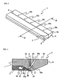
- FIG. 2 is an oblique view of the slot nozzle assembly 2.
- FIG. 3 is a cross-section view of the slot nozzle assembly 2 taken along line III-III in FIG. 2 .
- FIG. 4 is a partial enlarged view of the slot nozzle assembly 2.
- FIG. 5 is an oblique view of the front nozzle block 6.
- the front nozzle block 6 is provided with the five vertical passages 20, and with the single shared first lateral distribution flow route 21, which extends horizontally.
- the first lateral distribution flow route 21 is formed at the rear face 6a of the front nozzle block 6, and extends along the longitudinal direction of the front nozzle block 6.
- the inlets 20a of the five vertical passages 20 open in the top face 6b of the front nozzle block 6.
- the outlets 20b of the 5 vertical passages 20 open at the first lateral distribution flow route 21.
- the inlets 20a of the five vertical passages 20 respectively communicate with the five opening/closing valves (not shown in the drawing) provided in the control module 3. When the opening/closing valves are open, the foamable melted material flows to the inlets 20a of the vertical passages 20, passes through the vertical passages 20, and flows into the first lateral distribution flow route 21 from the outlets 20b.
- FIG. 6 is an oblique view of the rear nozzle block 7.
- the second lateral distribution flow route 22 is formed in the front face 7a of the rear nozzle block 7.
- the rear face 6a of the front nozzle block at 6 faces the front face 7a of the rear nozzle block 7 with the shim plate 8 between them.
- the second lateral distribution flow route 22 extends along the longitudinal direction of the rear nozzle block 7 and faces the first lateral distribution flow route 21.
- the converging portion 22a which extends downward, is provided at the second lateral distribution flow route 22.
- the converging portion 22a has a depth, i.e. groove thickness, which decreases doing downward.
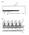
- FIG. 7 is an oblique view of the shim plate 8.
- FIG. 8 is a partial enlarged view of the shin plate 8.
- the shin plate 8 is disposed between the front nozzle block 6 and the rear nozzle block 7.
- Many narrow through holes 8a are provided in the portion of the shim plate 8 facing the first lateral distribution flow route 21.
- the many narrow through holes 8a communicate between the first lateral distribution flow route 21 and second lateral distribution flow route 22.
- a cut-out part 8b is provided in the shim plate 8.
- the cut-out part 8b of the shim plate 8 defines the slot 23 using the rear face 6a of the front nozzle block at 6 and the front face 7a of the rear nozzle block 7.
- the width of the slot 23 is determined by the width W of the cut-out part 8b.
- the width of the slot 23 determines the width of the band of foam that is coated on the substrate 5. It is possible to change the foam application pattern by changing the shape of the cut-out part 8b of the shim plate 8.
- the many narrow through holes 8a of the shim plate 8 function as a restriction member for limiting the flow of the foamable melted material from the first lateral distribution flow route 21 to the second lateral distribution flow route 22. Because of the shim plate 8, the pressure of the foamable melted material inside the first lateral distribution flow route 21 is kept at critical pressure or higher. As a result, foaming inside the slot nozzle assembly 2 is prevented. Also, because of the shim plate 8, the foamable melted material inside the first lateral distribution flow route 21 is dispersed in the lateral direction. As a result, the pressure and speed distribution of the foamable melted material inside the first lateral distribution flow route 21 are made uniform. That is, the shim plate 8 functions as a dispersing plate.
- the foamable melted material inside the first lateral distribution flow route 21 passes through the many narrow through holes 8a and flows to the second lateral distribution flow route 22.
- the foamable melted material passes through the converging portion 22a of the second lateral distribution flow route 22 and flows to the slot 23.
- the thickness T of the slot 23 is set small so that the pressure of the foamable melted material inside the second lateral distribution flow route 22 is kept at critical pressure or higher.
- the thickness T of the slot 23 can be changed by changing the thickness of the shim plate 8.
- FIG. 9 is an explanatory drawing which schematically shows the flow of the foamable melted material in the interior of a slot nozzle assembly in accordance with this embodiment, and bubbles in the foam layer coated on the substrate.
- the opening/closing valves (not shown in the drawing) of the valve assemblies 28 ( FIG. 14 ) provided in the control module 3 open, the foamable melted material passes through the vertical passages 20 as indicated by arrows F and flows to the first lateral distribution flow route 21.
- the foamable melted material is dispersed in the lateral direction along the first lateral distribution flow route 21 as indicated by arrows G, and passes through the many narrow through holes 8a of the shim plate 8 and flows to the second lateral distribution flow route 22.
- the many narrow through holes 8a of the shim plate 8 function as a restriction member for limiting the flow of the foamable melted material from the first lateral distribution flow route 21 to the second lateral distribution flow route 22, so the pressure of the foamable melted material inside the first lateral distribution flow route 21 is kept at critical pressure or higher. Also, the shim plate 8 functions as a dispersing plate, so the foamable melted material inside the first lateral distribution flow route 21 is dispersed in the lateral direction, and the pressure and speed distribution of the foamable melted material inside the first lateral distribution flow route 21 are made essentially uniform.
- the foamable melted material inside the second lateral distribution flow route 22 passes through the converging portion 22a and flows to the slot 23.
- the thickness T of the slot 23 is set small, so the pressure of the foamable melted material inside the second lateral distribution flow route 22 is kept at critical pressure or higher.
- the foamable melted material extruded from the slot 23 foams and forms a foam layer 24 of a certain thickness on the substrate 5.
- the pressure and speed of the foamable melted material in the longitudinal direction of the slot 23 are essentially uniform, so the thickness of the foam layer 24 is essentially uniform in the substrate's width direction, and the diameters of bubbles 24a inside the foam layer 24 are also essentially uniform.
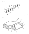
- FIG. 10 is an oblique view of the air block 9.
- FIG. 11 is a cross-section view of the air block 9 taken along line XI-XI in FIG. 10 .
- the air block 9 is provided with a lateral air passage 9a extending inside the air block 9 in the longitudinal direction.
- the air block 9 is provided with a slanted groove 9c extending in the longitudinal direction at a slanted face 9b.
- One end of the slanted groove 9c is connected to a vertical groove 9e extending to the bottom face 9d of the air block 9.
- the other end of the slanted groove 9c is connected to a first slanted air passage 9f communicating with the lateral air passage 9a.
- a plurality of ribs 9g are provided at the slanted groove 9c for rectifying the flow of air.
- the plurality of ribs 9g extends downward along the slanted face from the other end of the slanted groove 9c.
- the slanted groove 9c of the air block 9 and the bottom face 7b of the rear nozzle block 7 form a second slanted air passage 25.
- a rib part 7c that is capable of touching the substrate 5 is provided at the rear nozzle block 7.
- a side face 7d of the rib part 7c and a vertical groove 9e of the air block 9 form a vertical air passage 26.
- the hot air outlet 26a is formed as an air slit at the downstream side and near the foamable melted material outlet 23a of the slot 23. Hot air from the hot air outlet 26a smoothly peels the foam from the nozzle surface for transfer to the substrate.
- FIG. 12 is an explanatory diagram showing the flow of hot air.
- FIG. 13 is an explanatory diagram showing how the flow of hot air prevents the foam from rolling up.
- the lateral air passage 9a of the air block 9 communicates with the hot air source 10.
- the hot air source 10 supplies hot air to the lateral air passage 9a.
- the hot air as indicated by arrows J and K, passes from the lateral air passage 9a through the first slanted air passage 9f and second slanted air passage 25 and flows to the vertical air passage 26.
- the hot air, as indicated by arrow L is discharged from the hot air outlet 26a of the vertical air passage 26.
- the hot air prevents the foam of the foamable melted material extruded from the foamable melted material outlet 23a of the slot 23 from adhering to the slot nozzle assembly 2. Also, the hot air separates foam adhered to the slot nozzle assembly 2 from the surface of the slot nozzle assembly 2.
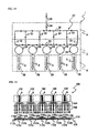
- FIG. 14 is an explanatory diagram showing the ladder-type foamable melted material distribution manifold 27 of the slot coating gun 1.
- Five valve assemblies 28 are provided in the control module 3, and these valve assemblies 28 respectively communicate with the vertical passages 20 provided in the front nozzle block 6.
- the first lateral distribution passage 29 is provided in the control module 3, and the first lateral distribution passage 29 communicates with the five valve assemblies 28.
- the second lateral distribution passage 30 is provided in the gun body 4. Both ends of the first lateral distribution passage 29 of the control module 3 and both ends of the second lateral distribution passage 30 of the gun body 4 communicate respectively via the end passage 31 and end passage 32. Also, the first lateral distribution passage 29 and the second lateral distribution passage 30 of the gun body 4 communicate by a traverse passage 33 between adjacent valve assemblies 28.
- the gun body 4 is provided with the inlet passage 34 connected to the hot melt hose 19 connected to the foamable melted material supply system 11; the inlet passage 34 is connected to the second lateral distribution passage 30.
- the foamable melted material distribution manifold 27 is constituted in a ladder shape by the second lateral distribution passage 30, end passage 31, end passage 32, and four traverse passages 33.
- the foamable melted material goes from the foamable melted material supply system 11 through the hot melt hose 19 and inlet passage 34 and is sent to the ladder-style foamable melted material distribution manifold 27.
- the inlet passage 34 is connected to essentially the center of the second lateral distribution passage 30 of the gun body 4.
- Foamable melted material from the inlet passage 34 is distributed left and right from essentially the center of the second lateral distribution passage 30, and flows to the traverse passages 33 and the end passage 31 and end passage 32 respectively at both ends of the lateral distribution passages.
- Foamable melted material from the traverse passages 33, end passage 31, and end passage 32 enters the first lateral distribution passage 29 of the control module 3.
- the foamable melted material is supplied to the respective five valve assemblies 28 communicating with the first lateral distribution passage 29 from both directions of the first lateral distribution passage 29. Therefore, the pressure and flow amount of the foamable melted material supplied to the five valve assemblies 28 are essentially the same. Accordingly, the pressure and flow amount of the foamable melted material supplied from the valve assemblies 28 to the vertical passages 20 of the front nozzle block 6 are essentially uniform, as indicated by the thickness of the arrows S in FIG. 14 . In this manner, by providing the ladder-type foamable melted material distribution manifold 27 of the present embodiment, the pressure and flow amount of the foamable melted material supplied to the plurality of the valve assemblies 28 become essentially uniform.
- the pressure of the foamable melted material inside the slot nozzle assembly at critical pressure or higher and to prevent foaming in the interior.
- the design of the new flow route makes it possible to achieve uniform flow speed and pressure in the process of dispersing thinly and widely.
- the hot air discharged from the slit-shaped hot air outlet provided downstream from the slot makes it possible to peel foam extruded from the slot from the nozzle and to assist in transfer of the foam to the substrate.
- the foamable melted material is a foaming adhesive, it is possible to form a thick adhesive layer with just a little adhesive, and to conserve on material expenses.
- a soft foam layer acts as a cushion.
- glue adhesive tape to a nonuniform surface.
- the thickness of the foam coated on a substrate can be made essentially uniform.
- the device and method for extruding a foamable melted material according to the present invention can be generally applied to all contact coating which uses a slot nozzle, such as label gluing, seals, gaskets, etc.
- the "foamable melted material” in this specification is a mixture of a polymeric substance and a gas.
- the foamable melted material is one in which a gas such as air or nitrogen or carbon dioxide, etc. is dissolved under pressure in a unvulcanized rubber, saturated polyester, polyamide, polyolefin, polyolefin copolymer or a modification thereof.
- a gas such as air or nitrogen or carbon dioxide, etc.
- the gas dissolved in the foamable melted material foams and creates a multitude of independent bubbles, and its volume swells in a range from 1.5 times to 5 times.
Landscapes
- Chemical & Material Sciences (AREA)
- Dispersion Chemistry (AREA)
- Chemical Kinetics & Catalysis (AREA)
- Coating Apparatus (AREA)
- Application Of Or Painting With Fluid Materials (AREA)
- Extrusion Moulding Of Plastics Or The Like (AREA)
- Molding Of Porous Articles (AREA)
- Casting Or Compression Moulding Of Plastics Or The Like (AREA)
- Lining Or Joining Of Plastics Or The Like (AREA)
Description
- The present invention pertains to a slot coating gun and a method of extruding a foamable melted material in a wide band.
- In the past, in the field of adhesives and sealing materials, foam melt applicators for coating a foamable melted material have been known (for example, see Patent Document 1). A foam melt applicator is a device which mechanically mixes an inert gas into melted hot melt and discharges a bubbly hot melt. Coating a foamable melted material can reduce running costs and lengthen open time before clamping. Other effects include shortening the setting time after clamping, making it easier to thinly spread an adhesive layer after clamping, increased adhesion strength with porous materials, increased filling efficiency on a bonded item that has a rough surface, formation of a coating film with elasticity, etc. Therefore foamable melted materials are widely used.
- For example, there are a device and method which manufacture an insulated plate by spreading foaming-type hot melt from a slot nozzle onto a long narrow band of material that is continuously transported, and gluing another long narrow band of material thereon (for example, see Patent Document 2).
- Also, in order to prevent premature foaming of a foamable melted material inside a slot nozzle, there is a slot nozzle which can keep a foamable melted material at a pressure higher than the critical pressure at which the foamable melted material does not foam until the foamable melted material reaches the outlet part of the slot (for example, see Patent Document 3). This slot nozzle is provided with a converging slot part in which the thickness of the slot is gradually reduced from the wide slot part, where the slot is thick, to the outlet slot part, where the slot is thin.
- Patent Document 1:
JP S59-182825 A - Patent Document 2:
JP S57-110440 A - Patent Document 3:
JP H7-308618 A - To coat a foamable melted material in a wide band one must use a slotted discharge device. When one attempts to discharge foamable melted material with a slotted discharge device, many intrinsic problems occur.
- Usually, a foamable melted material foams after being extruded from a slotted discharge device and forms a foam layer on the substrate. However, sometimes a bubbling sound can be heard from the slotted discharge device, and in this sort of case, holes occur in the foam layer formed on the substrate. This is because before the foamable melted material was extruded from the slotted discharge device, gases dissolved in the foamable melted material started to foam inside the slotted discharge device and premature foaming occurred. When premature foaming occurs, the texture of the foam layer becomes unallowably rough, and holes are formed in the foam layer. A foam layer that has holes reduces the quality of the product. Therefore, one must keep the pressure inside a slotted discharge device at a pressure higher than the critical pressure at which the foamable melted material starts to foam so that the foamable melted material does not foam inside the slotted discharge device.
- In addition, a foamable melted material must be uniformly distributed across the entire width of the slot. Therefore, it is necessary to disperse the foamable melted material widely and thinly in the interior of a slotted discharge device.
If the flow speed of the foamable melted material inside a slotted discharge device is nonuniform, or if the pressure distribution of the foamable melted material is biased, the diameter of bubbles inside the foam layer coated on the substrate becomes nonuniform. -
FIG. 15 is an explanatory diagram schematically showing the flow of a foamable melted material in the interior of a conventional slot nozzle assembly and bubbles in the foam layer coated on a substrate.
Aslot nozzle assembly 100 is attached to a control module 118 (FIG. 17 ). Theslot nozzle assembly 100 is provided with fivevertical passages 102. Thevertical passages 102 respectively communicate with valve assemblies 120 (FIG. 17 ) provided in the control module 118 (FIG. 17 ). The fivevertical passages 102 communicate with a single lateraldistribution flow route 104 provided in theslot nozzle assembly 100. The lateraldistribution flow route 104 communicates with aslender slot 106 which extends in the longitudinal direction of theslot nozzle assembly 100. - When a valve (not shown in the drawing) opens in the valve assembly 120 (
FIG. 17 ), the foamable melted material passes through thevertical passage 102 as indicated by arrow A and flows to the lateraldistribution flow route 104. In the lateraldistribution flow route 104, the foamable melted material is laterally dispersed along the lateraldistribution flow route 104 as indicated by arrows B, C, D, and E, passes through theslot 106, is extruded on asubstrate 108, and forms afoam layer 110. The thickness of the arrows A, B, C, D, and E represents the flow amount of foamable melted material. The flow amount of foamable melted material flowing from the lateraldistribution flow route 104 to theslot 106 is large directly under thevertical passage 102 as indicated by arrow B, and the flow amount diminishes with distance from thevertical passage 102 as indicated by the thicknesses of arrows C, D, and E. Pressure also diminishes with the reduction in flow amount. - These changes in flow amount and pressure change the thickness of the
foam layer 110 formed on thesubstrate 108 and the diameter of its bubbles. InFIG. 15 , thesubstrate 108 is transported in the direction perpendicular to the drawing.FIG. 15 shows a cross-section view of thefoam layer 110 taken along the direction perpendicular to thesubstrate 108's transport direction. Thefoam layer 110 includes a thick-layer portion 110a formed directly under thevertical passage 102 and a thin-layer portion 110b formed between adjacentvertical passages 102. The diameter of abubble 112a formed inside the thick-layer portion 110a is small, and the diameter of a bubble 112b formed inside the thin-layer portion 110b is large. Changes in the thicknesses of these layers and the bubble diameters appear as lines in the band-like foam layer 110 coated on thesubstrate 108. That is, the thick-layer portion 110a, which has small bubbles under thevertical passage 102, appears as five lines, and the thin-layer portion 110b, which has large bubbles between adjacentvertical passages 102, appears as six lines. These two types of lines appear alternatingly aligned in the width direction of the band-like foam layer 110. These lines greatly diminish the quality of the product, and worsen the product appearance. -
FIG. 16 is an explanatory diagram showing foam accumulated on the surface of the rear nozzle block of a conventional slot nozzle assembly.
Thesubstrate 108 is transported in the direction indicated by arrow X. Theslot nozzle assembly 100 consists of afront nozzle block 114 and arear nozzle block 116; theslot 106 is formed between thefront nozzle block 114 and therear nozzle block 116. Thefront nozzle block 114 is positioned at the upstream side of thesubstrate 108's transport direction X. Therear nozzle block 116 is positioned at the downstream side of thesubstrate 108's transport direction X. - The foamable melted material extruded from the
outlet 106a of theslot 106 foams and coats thesubstrate 108 and forms thefoam layer 110 at the downstream side of the transport direction X. When doing so,part 110c of the foam coated on thesubstrate 108 adheres to thesurface 116a of therear nozzle block 116. Also, the volume of the foam may sometimes become very large and it adheres to thesurface 116a of therear nozzle block 116.Foam part 110c gradually accumulates, and deteriorates. Subsequently, thefoam part 110c drips on thefoam layer 110. In particular, large drips of foam are visible on the foam layer, so the product is soiled and the quality of the product is reduced. -
FIG. 17 is an explanatory drawing showing a foamable meltedmaterial distribution manifold 210 of a conventionalslot coating gun 200.
Theslot coating gun 200 consists of aslot nozzle assembly 100,control module 118, andgun body 122. Thecontrol module 118 is provided with fivevalve assemblies 120, and thesevalve assemblies 120 respectively communicate with thevertical passages 102 provided in theslot nozzle assembly 100. A lateraldistributional passage 130 is provided in thecontrol module 118, and thelateral distribution passage 130 communicates with the fivevalve assemblies 120. Alateral distribution passage 132 is provided in thegun body 122. The two ends of thelateral distribution passage 130 of thecontrol module 118 communicate with the two ends of thelateral distribution passage 132 of thegun body 122 viapassage 134 andpassage 136 respectively. A passage 138 is provided in thegun body 122 so that thelateral distribution passage 132 communicates with a foam station (not shown in the drawing). The foamable meltedmaterial distribution manifold 210 is constituted by thelateral distribution passage 130,lateral distribution passage 132,passage 134, andpassage 136. - Foamable melted material is sent from a foam station (not shown in the drawing) through the passage 138 to the foamable melted
material distribution manifold 210. The passage 138 is connected to essentially the center of thelateral distribution passage 132 of thegun body 122. Foamable melted material from the passage 138 is distributed left and right from essentially the center of thelateral distribution passage 132, and flows to thepassage 134 andpassage 136 respectively at both ends of thelateral distribution passage 132. Foamable melted material from thepassage 134 andpassage 136 enters both ends of thelateral distribution passage 130 of thecontrol module 118, and flows toward the center of thelateral distribution passage 130. The foamable melted material is supplied to the fivevalve assemblies 120, which communicate with thelateral distribution passage 130. The pressure and flow amount of the foamable melted material supplied to thevalve assemblies 120 near both ends of thelateral distribution passage 130 become larger than the pressure and flow amount of the foamable melted material supplied to thevalve assemblies 120 at the center of thelateral distribution passage 130. Therefore, the pressure and flow amount of the foamable melted material supplied from thevalve assemblies 120 to thevertical passages 102 of theslot nozzle assembly 100 gradually become smaller from both ends of theslot nozzle assembly 100 towards its center, as indicated by the thickness of arrows P, Q, and R inFIG. 17 . Thus there is a problem with nonuniform pressure and flow amount of the foamable melted material supplied from the foamable meltedmaterial distribution manifold 210 to the plurality ofvalve assemblies 120. - The present invention is a slot coating gun with the features of
claim 1.
That is, a slot coating gun (1) for extruding a foamable melted material in a wide band was provided with an inlet passage (34) for receiving foamable melted material, a plurality of valve assemblies (28), a foamable melted material distribution manifold (27) communicating with the inlet passage and the plurality of valve assemblies, a slot nozzle assembly having a plurality of foamable melted material passages (20) respectively communicating with the plurality of valve assemblies, lateral distribution flow routes (21, 22) communicating with the plurality of foamable melted material passages, a restriction member (8) disposed inside the lateral distribution flow routes, a slot (23) for discharging foamable melted material, and a converging portion (22a) which communicates with the lateral distribution flow routes and the slot, and whose cross-section area gradually becomes smaller toward the slot. The foamable melted material distribution manifold comprises a first lateral distribution passage (29) communicating with the plurality of valve assemblies, a second lateral distribution passage (30) communicating with the inlet passage, two end passages (31, 32) respectively connecting both ends of the first lateral distribution passage and both ends of the second lateral distribution passage, and a plurality of traverse passages (33) connecting the first lateral distribution passage and the second lateral distribution passage at points respectively between adjacent valve assemblies. - As a result, it is possible to make the pressure and flow amount of the foamable melted material supplied to the plurality of valve assemblies essentially uniform.
- A hot air outlet (26a) for discharging hot air may be provided at the downstream side of the slot in the transport direction of a substrate on which a foaming melting material is coated.
As a result, the foam of the extruded foamable melted material is separated from the nozzle surface by the hot air. That is, it makes it easy to peel off foam adhered to the nozzle. - Also, the present invention is a method of extruding a foamable melted material in a wide band, in accordance with
claim 6.
Disclosed is also a method of extruding a foamable melted material in a wide band, and included a step of passing a foamable melted material from the plurality of foamable melted material passages (20) to the first lateral distribution flow route (21), a step of restricting the flow of the foamable melted material from the first lateral distribution flow route to the second lateral distribution flow route (22) using a dispersing plate (8) in order to keep the pressure of the foamable melted material inside the first lateral distribution flow route at critical pressure or higher, a step of restricting the flow of the foamable melted material from the second lateral distribution flow route to the slot (23) using the thickness (T) of the slot in order to keep the pressure of the foamable melted material inside the second lateral distribution flow route at critical pressure or higher, and a step of extruding the foamable melted material from the slot to a substrate in a wide band.
As a result, it is possible to keep the pressure of the foamable melted material inside the slot [sic] first lateral distribution flow route and second lateral distribution flow route at critical pressure or higher so that foaming does not occur before the foamable melted material is discharged. Also, it is possible to make the pressure and flow distribution of the foamable melted material in the first and second lateral distribution float routes essentially uniform. - Below, the present invention shall be described based on a preferred embodiment, with reference to drawings. However, the dimensions, material, shape, relative dispositions, etc. of the constituent components described in the following embodiments do not restrict the scope of this invention, as long as they are not specially and particularly described.
-
-
FIG. 1 : A diagram showing one embodiment in accordance with the present invention, including a slot coating gun and a system for supplying foamable melted material. -
FIG. 2 : An oblique view of the slot nozzle assembly. -
FIG. 3 : A cross-section view of the slot nozzle assembly taken along line III-III inFIG. 2 . -
FIG. 4 : A partial enlarged view of the slot nozzle assembly. -
FIG. 5 : An oblique view of the front nozzle block. -
FIG. 6 : An oblique view of the rear nozzle block. -
FIG. 7 : An oblique view of the shim plate. -
FIG. 8 : A partial enlarged view of the shin plate. -
FIG. 9 : An explanatory drawing which schematically shows the flow of the foamable melted material in the interior of a slot nozzle assembly in accordance with this embodiment, and bubbles in the foam layer coated on the substrate. -
FIG. 10 : An oblique view of the air block. -
FIG. 11 : A cross-section view of the air block taken along line XI-XI inFIG. 10 . -
FIG. 12 : An explanatory diagram showing the flow of hot air. -
FIG. 13 : An explanatory diagram showing how the flow of hot air prevents the foam from rolling up. -
FIG. 14 : An explanatory diagram showing the ladder-type foamable melted material distribution manifold of the slot coating gun. -
FIG. 15 : An explanatory diagram schematically showing the flow of a foamable melted material in the interior of a conventional slot nozzle assembly and bubbles in the foam layer coated on a substrate. -
FIG. 16 : An explanatory diagram shows foam accumulated on the surface of the rear nozzle block of a conventional slot nozzle assembly. -
FIG. 17 : An explanatory drawing showing a foamable melted material distribution manifold of a conventional slot coating gun. -
FIG. 1 is a diagram showing one embodiment in accordance with the present invention, including a slot coating gun and a system for supplying a foamable melted material. - The wide
slot coating gun 1 consists of theslot nozzle assembly 2,control module 3, andgun body 4. A wideflat substrate 5 is transported in the direction indicated by arrow X below theslot nozzle assembly 2, either touching or not touching theslot nozzle assembly 2. Theslot nozzle assembly 2 consists of thefront nozzle block 6,rear nozzle block 7,shim plate 8 disposed between thefront nozzle block 6 andrear nozzle block 7, and anair block 9 attached to therear nozzle block 7. Thefront nozzle block 6 is positioned at the upstream side of thesubstrate 5's transport direction X. Therear nozzle block 7 is positioned at the downstream side of thesubstrate 5's transport direction X. Theair block 9 is supplied with hot air from ahot air source 10. - The
gun body 4 is supplied with a foamable melted material from a foamable meltedmaterial supply system 11. Thegun body 4 is provided with a cartridge heater (not shown in the drawing) and a temperature sensor (not shown in the drawing). The foamable melted material passes through thegun body 4 and is sent to thecontrol module 3. - The
control module 3 is provided with an opening/closing valve (not shown in the drawing). When the opening/closing valve is open, the foamable melted material flows to theslot nozzle assembly 2. When the opening/closing valve is closed, flow of foamable melted material to theslot nozzle assembly 2 is interrupted. - The foamable melted
material supply system 11 consists of a meltedmaterial supply source 12, a foam station 13, and aquantitative pump 14. - The melted
material supply source 12 consists of a tank and a heater for melting a solid or semi-solid polymeric substance in the tank. The melted material inside the tank is supplied to the foam station 13. - The foam station 13 mixes a gas (dry air, nitrogen gas, carbon dioxide gas, etc.) into the melted polymeric substance and makes a foamable melted material. The foamable melted material is kept in a mixed state (liquid state) as long as it is at the critical pressure at which the gas dissolved in the melted substance starts to foam or at a higher pressure. When the foaming melted substance is exposed to atmospheric pressure, the gas is generated from the melted substance in the form of bubbles and forms a foam, and the bubbles enlarge and the volume expands.
- The foam station 13 consist of a first pump (gear pump) 15, a second pump (
gear pump 16, agas supply source 17, and amixer 18. Thefirst pump 15 pressurizes and sends melted material from the meltedmaterial supply source 12 to thesecond pump 16. Thegas supply source 17 introduces a gas into the melted material between thefirst pump 15 and thesecond pump 16. By setting a difference in flow amounts between thefirst pump 15 and thesecond pump 16, gas is introduced from thegas supply source 17 into the melted material. Themixer 18 receives the melted material, to which gas has been introduced from thesecond pump 16, mixes the gas in the melted material, and makes the foamable melted material. Foamable melted material from themixer 18 is supplied to thegun body 4 of theslot coating gun 1 by thequantitative pump 14 via ahot melt hose 19. -
FIG. 2 is an oblique view of theslot nozzle assembly 2.FIG. 3 is a cross-section view of theslot nozzle assembly 2 taken along line III-III inFIG. 2 .FIG. 4 is a partial enlarged view of theslot nozzle assembly 2. -
FIG. 5 is an oblique view of thefront nozzle block 6. Thefront nozzle block 6 is provided with the fivevertical passages 20, and with the single shared first lateraldistribution flow route 21, which extends horizontally. The first lateraldistribution flow route 21 is formed at therear face 6a of thefront nozzle block 6, and extends along the longitudinal direction of thefront nozzle block 6. Theinlets 20a of the fivevertical passages 20 open in thetop face 6b of thefront nozzle block 6. Theoutlets 20b of the 5vertical passages 20 open at the first lateraldistribution flow route 21.
Theinlets 20a of the fivevertical passages 20 respectively communicate with the five opening/closing valves (not shown in the drawing) provided in thecontrol module 3. When the opening/closing valves are open, the foamable melted material flows to theinlets 20a of thevertical passages 20, passes through thevertical passages 20, and flows into the first lateraldistribution flow route 21 from theoutlets 20b. -
FIG. 6 is an oblique view of therear nozzle block 7. The second lateraldistribution flow route 22 is formed in the front face 7a of therear nozzle block 7. When theslot nozzle assembly 2 is assembled, therear face 6a of the front nozzle block at 6 faces the front face 7a of therear nozzle block 7 with theshim plate 8 between them. The second lateraldistribution flow route 22 extends along the longitudinal direction of therear nozzle block 7 and faces the first lateraldistribution flow route 21.
The convergingportion 22a, which extends downward, is provided at the second lateraldistribution flow route 22. The convergingportion 22a has a depth, i.e. groove thickness, which decreases doing downward. -
FIG. 7 is an oblique view of theshim plate 8.FIG. 8 is a partial enlarged view of theshin plate 8. Theshin plate 8 is disposed between thefront nozzle block 6 and therear nozzle block 7. Many narrow throughholes 8a are provided in the portion of theshim plate 8 facing the first lateraldistribution flow route 21. The many narrow throughholes 8a communicate between the first lateraldistribution flow route 21 and second lateraldistribution flow route 22.
Also, a cut-outpart 8b is provided in theshim plate 8. The cut-outpart 8b of theshim plate 8 defines theslot 23 using therear face 6a of the front nozzle block at 6 and the front face 7a of therear nozzle block 7. The width of theslot 23 is determined by the width W of the cut-outpart 8b. The width of theslot 23 determines the width of the band of foam that is coated on thesubstrate 5.
It is possible to change the foam application pattern by changing the shape of the cut-outpart 8b of theshim plate 8. - The many narrow through
holes 8a of theshim plate 8 function as a restriction member for limiting the flow of the foamable melted material from the first lateraldistribution flow route 21 to the second lateraldistribution flow route 22. Because of theshim plate 8, the pressure of the foamable melted material inside the first lateraldistribution flow route 21 is kept at critical pressure or higher. As a result, foaming inside theslot nozzle assembly 2 is prevented. Also, because of theshim plate 8, the foamable melted material inside the first lateraldistribution flow route 21 is dispersed in the lateral direction. As a result, the pressure and speed distribution of the foamable melted material inside the first lateraldistribution flow route 21 are made uniform. That is, theshim plate 8 functions as a dispersing plate. - The foamable melted material inside the first lateral
distribution flow route 21 passes through the many narrow throughholes 8a and flows to the second lateraldistribution flow route 22. The foamable melted material passes through the convergingportion 22a of the second lateraldistribution flow route 22 and flows to theslot 23. The thickness T of theslot 23 is set small so that the pressure of the foamable melted material inside the second lateraldistribution flow route 22 is kept at critical pressure or higher. The thickness T of theslot 23 can be changed by changing the thickness of theshim plate 8. -
FIG. 9 is an explanatory drawing which schematically shows the flow of the foamable melted material in the interior of a slot nozzle assembly in accordance with this embodiment, and bubbles in the foam layer coated on the substrate.
When the opening/closing valves (not shown in the drawing) of the valve assemblies 28 (FIG. 14 ) provided in thecontrol module 3 open, the foamable melted material passes through thevertical passages 20 as indicated by arrows F and flows to the first lateraldistribution flow route 21. At the first lateraldistribution flow route 21, the foamable melted material is dispersed in the lateral direction along the first lateraldistribution flow route 21 as indicated by arrows G, and passes through the many narrow throughholes 8a of theshim plate 8 and flows to the second lateraldistribution flow route 22. The many narrow throughholes 8a of theshim plate 8 function as a restriction member for limiting the flow of the foamable melted material from the first lateraldistribution flow route 21 to the second lateraldistribution flow route 22, so the pressure of the foamable melted material inside the first lateraldistribution flow route 21 is kept at critical pressure or higher. Also, theshim plate 8 functions as a dispersing plate, so the foamable melted material inside the first lateraldistribution flow route 21 is dispersed in the lateral direction, and the pressure and speed distribution of the foamable melted material inside the first lateraldistribution flow route 21 are made essentially uniform. - The foamable melted material inside the second lateral
distribution flow route 22 passes through the convergingportion 22a and flows to theslot 23. The thickness T of theslot 23 is set small, so the pressure of the foamable melted material inside the second lateraldistribution flow route 22 is kept at critical pressure or higher. The foamable melted material extruded from theslot 23 foams and forms afoam layer 24 of a certain thickness on thesubstrate 5. The pressure and speed of the foamable melted material in the longitudinal direction of theslot 23 are essentially uniform, so the thickness of thefoam layer 24 is essentially uniform in the substrate's width direction, and the diameters ofbubbles 24a inside thefoam layer 24 are also essentially uniform. -
FIG. 10 is an oblique view of theair block 9.FIG. 11 is a cross-section view of theair block 9 taken along line XI-XI inFIG. 10 .
Theair block 9 is provided with alateral air passage 9a extending inside theair block 9 in the longitudinal direction. Theair block 9 is provided with aslanted groove 9c extending in the longitudinal direction at aslanted face 9b. One end of the slantedgroove 9c is connected to avertical groove 9e extending to thebottom face 9d of theair block 9. The other end of the slantedgroove 9c is connected to a firstslanted air passage 9f communicating with thelateral air passage 9a. A plurality of ribs 9g are provided at the slantedgroove 9c for rectifying the flow of air. The plurality of ribs 9g extends downward along the slanted face from the other end of the slantedgroove 9c. - Referring to
FIG. 4 , when theair block 9 is fitted to therear nozzle block 7, the slantedgroove 9c of theair block 9 and thebottom face 7b of therear nozzle block 7 form a secondslanted air passage 25. Arib part 7c that is capable of touching thesubstrate 5 is provided at therear nozzle block 7. A side face 7d of therib part 7c and avertical groove 9e of theair block 9 form avertical air passage 26. As a result, thehot air outlet 26a is formed as an air slit at the downstream side and near the foamable melted material outlet 23a of theslot 23. Hot air from thehot air outlet 26a smoothly peels the foam from the nozzle surface for transfer to the substrate. -
FIG. 12 is an explanatory diagram showing the flow of hot air.FIG. 13 is an explanatory diagram showing how the flow of hot air prevents the foam from rolling up.
Thelateral air passage 9a of theair block 9 communicates with thehot air source 10. Thehot air source 10 supplies hot air to thelateral air passage 9a. The hot air, as indicated by arrows J and K, passes from thelateral air passage 9a through the firstslanted air passage 9f and secondslanted air passage 25 and flows to thevertical air passage 26. The hot air, as indicated by arrow L, is discharged from thehot air outlet 26a of thevertical air passage 26. The hot air prevents the foam of the foamable melted material extruded from the foamable melted material outlet 23a of theslot 23 from adhering to theslot nozzle assembly 2. Also, the hot air separates foam adhered to theslot nozzle assembly 2 from the surface of theslot nozzle assembly 2. -
FIG. 14 is an explanatory diagram showing the ladder-type foamable meltedmaterial distribution manifold 27 of theslot coating gun 1.
Fivevalve assemblies 28 are provided in thecontrol module 3, and thesevalve assemblies 28 respectively communicate with thevertical passages 20 provided in thefront nozzle block 6. The firstlateral distribution passage 29 is provided in thecontrol module 3, and the firstlateral distribution passage 29 communicates with the fivevalve assemblies 28. The secondlateral distribution passage 30 is provided in thegun body 4. Both ends of the firstlateral distribution passage 29 of thecontrol module 3 and both ends of the secondlateral distribution passage 30 of thegun body 4 communicate respectively via the end passage 31 andend passage 32. Also, the firstlateral distribution passage 29 and the secondlateral distribution passage 30 of thegun body 4 communicate by atraverse passage 33 betweenadjacent valve assemblies 28. Thegun body 4 is provided with the inlet passage 34 connected to thehot melt hose 19 connected to the foamable meltedmaterial supply system 11; the inlet passage 34 is connected to the secondlateral distribution passage 30. The foamable meltedmaterial distribution manifold 27 is constituted in a ladder shape by the secondlateral distribution passage 30, end passage 31,end passage 32, and fourtraverse passages 33. - The foamable melted material goes from the foamable melted
material supply system 11 through thehot melt hose 19 and inlet passage 34 and is sent to the ladder-style foamable meltedmaterial distribution manifold 27. The inlet passage 34 is connected to essentially the center of the secondlateral distribution passage 30 of thegun body 4. Foamable melted material from the inlet passage 34 is distributed left and right from essentially the center of the secondlateral distribution passage 30, and flows to thetraverse passages 33 and the end passage 31 andend passage 32 respectively at both ends of the lateral distribution passages. Foamable melted material from thetraverse passages 33, end passage 31, and endpassage 32 enters the firstlateral distribution passage 29 of thecontrol module 3. The foamable melted material is supplied to the respective fivevalve assemblies 28 communicating with the firstlateral distribution passage 29 from both directions of the firstlateral distribution passage 29. Therefore, the pressure and flow amount of the foamable melted material supplied to the fivevalve assemblies 28 are essentially the same. Accordingly, the pressure and flow amount of the foamable melted material supplied from thevalve assemblies 28 to thevertical passages 20 of thefront nozzle block 6 are essentially uniform, as indicated by the thickness of the arrows S inFIG. 14 . In this manner, by providing the ladder-type foamable meltedmaterial distribution manifold 27 of the present embodiment, the pressure and flow amount of the foamable melted material supplied to the plurality of thevalve assemblies 28 become essentially uniform. - According to the present embodiment, it is possible to keep the pressure of the foamable melted material inside the slot nozzle assembly at critical pressure or higher and to prevent foaming in the interior.
The design of the new flow route makes it possible to achieve uniform flow speed and pressure in the process of dispersing thinly and widely.
The hot air discharged from the slit-shaped hot air outlet provided downstream from the slot makes it possible to peel foam extruded from the slot from the nozzle and to assist in transfer of the foam to the substrate.
If the foamable melted material is a foaming adhesive, it is possible to form a thick adhesive layer with just a little adhesive, and to conserve on material expenses.
A soft foam layer acts as a cushion. Also, it is possible to glue adhesive tape to a nonuniform surface.
The thickness of the foam coated on a substrate can be made essentially uniform. - The device and method for extruding a foamable melted material according to the present invention can be generally applied to all contact coating which uses a slot nozzle, such as label gluing, seals, gaskets, etc.
- The "foamable melted material" in this specification is a mixture of a polymeric substance and a gas. For example, the foamable melted material is one in which a gas such as air or nitrogen or carbon dioxide, etc. is dissolved under pressure in a unvulcanized rubber, saturated polyester, polyamide, polyolefin, polyolefin copolymer or a modification thereof. At atmospheric pressure the gas dissolved in the foamable melted material foams and creates a multitude of independent bubbles, and its volume swells in a range from 1.5 times to 5 times.
- The present invention is not limited to the above embodiment, and can be practiced in various other configurations without deviating from its features. Therefore, the above-described embodiment is merely an example of each point, and is not to be interpreted as limiting. The scope of the present invention is indicated by the claims, and is not restricted whatsoever by the specification text. In addition, variations and modifications belonging to the same scope as the patent claims are all within the scope of the present invention.
-
-
FIG. 1 : A diagram showing one embodiment in accordance with the present invention, including a slot coating gun and a system for supplying foamable melted material. -
FIG. 2 : An oblique view of the slot nozzle assembly. -
FIG. 3 : A cross-section view of the slot nozzle assembly taken along line III-III inFIG. 2 . -
FIG. 4 : A partial enlarged view of the slot nozzle assembly. -
FIG. 5 : An oblique view of the front nozzle block. -
FIG. 6 : An oblique view of the rear nozzle block. -
FIG. 7 : An oblique view of the shim plate. -
FIG. 8 : A partial enlarged view of the shin plate. -
FIG. 9 : An explanatory drawing which schematically shows the flow of the foamable melted material in the interior of a slot nozzle assembly in accordance with this embodiment, and bubbles in the foam layer coated on the substrate. -
FIG. 10 : An oblique view of the air block. -
FIG. 11 : A cross-section view of the air block taken along line XI-XI inFIG. 10 . -
FIG. 12 : An explanatory diagram showing the flow of hot air. -
FIG. 13 : An explanatory diagram showing how the flow of hot air prevents the foam from rolling up. -
FIG. 14 : An explanatory diagram showing the ladder-type foamable melted material distribution manifold of the slot coating gun. -
FIG. 15 : An explanatory diagram schematically showing the flow of a foamable melted material in the interior of a conventional slot nozzle assembly and bubbles in the foam layer coated on a substrate. -
FIG. 16 : An explanatory diagram showing foam accumulated on the surface of the rear nozzle block of a conventional slot nozzle assembly. -
FIG. 17 : An explanatory drawing showing a foamable melted material distribution manifold of a conventional slot coating gun. -
- 1
- Slot coating gun
- 2
- Slot nozzle assembly
- 3
- Control module
- 4
- Gun body
- 5
- Substrate
- 6
- Front nozzle block
- 6a
- Rear face
- 6b
- Top face
- 7
- Rear nozzle block
- 7a
- Front face
- 7b
- Bottom face
- 7c
- Rib part
- 7d
- Side face
- 8
- Shim plate
- 8a
- Through hole
- 8b
- Cut-out part
- 9
- Air block
- 9a
- Lateral air passage
- 9b
- Slanted face
- 9c
- Slanted groove
- 9d
- Bottom face
- 9e
- Vertical groove
- 9f
- First slanted air passage
- 9g
- Rib
- 10
- Hot air source
- 11
- Foamable melted material supply system
- 12
- Melted material supply source
- 13
- Foam station
- 14
- Quantitative pump
- 15
- First pump
- 16
- Second pump
- 17
- Gas supply source
- 18
- Mixer
- 19
- Hot melt hose
- 20
- Vertical passage
- 20a
- Inlet
- 20b
- Outlet
- 21
- First lateral distribution flow route
- 22
- Second lateral distribution flow route
- 22a
- Converging portion
- 23
- Slot
- 23 a
- Foamable melted material outlet
- 24
- Foam layer
- 24a
- Bubble
- 25
- Second slanted air passage
- 26
- Vertical air passage
- 26a
- Hot air outlet
- 27
- Ladder-style foamable melted material distribution manifold
- 28
- Valve assembly
- 29
- First lateral distribution passage
- 30
- Second lateral distribution passage
- 31
- End passage
- 32
- End passage
- 33
- Traverse passage
- 34
- Inlet passage
- 100
- Slot nozzle assembly
- 102
- Vertical passage
- 104
- Lateral distribution flow route
- 106
- Slot
- 106a
- Outlet
- 108
- Substrate
- 110
- Foam layer
- 110a
- Thick layer portion
- 110b
- Thin layer portion
- 110c
- Foam part
- 112a
- Small bubble
- 112b
- Large bubble
- 114
- Front nozzle block
- 116
- Rear nozzle block
- 118
- Control module
- 120
- Valve assembly
- 122
- Gun body
- 130
- Lateral distribution passage
- 132
- Lateral distribution passage
- 134
- Passage
- 136
- Passage
- 138
- Passage
- 200
- Slot coating gun
- 210
- Filming the melted material distribution manifold
Claims (7)
- A slot coating gun (1) for extruding a foamable melted material in a wide band onto a substrate (5) comprising:an inlet passage (34) for receiving foamable melted material;a plurality of valve assemblies (28),a foamable melted material distribution manifold (27) communicating with said inlet passage (34) and said plurality of valve assemblies (28),a slot nozzle assembly (2) having a plurality of foamable melted material passages (20) respectively communicating with said plurality of valve assemblies (28),a lateral distribution flow route (21) communicating with said plurality of foamable melted material passages (20),a restriction member (8) disposed inside said lateral distribution flow route,and a slot (23) for discharging foamable melted material, anda converging portion (22) which communicates with said lateral distribution flow route (21) and said slot (23), and whose cross-section area gradually becomes smaller toward said slot;said foamable melted material distribution manifold (27) comprises a first lateral distribution passage (29) communicating with said plurality of valve assemblies (28), a second lateral distribution passage (30) communicating with said inlet passage (34), two end passages (31, 32) respectively connecting both ends of said first lateral distribution passage (29) and both ends of said second lateral distribution passage (30), characterized in that said foamable melted material distribution manifold further comprises a plurality of traverse passages (33) connecting said first lateral distribution passage (29) and said second lateral distribution passage (30) at points respectively between adjacent valve assemblies (28).
- A slot coating gun of claim 1, wherein the pressure and flow amount of the foamable melted material supplied to each of said valve assemblies (28) is essentially uniform and the pressure and flow amount of the foamable melted material respectively supplied from each of said plurality of valve assemblies (28) to each of said plurality of foamable melted material passages (20) is essentially uniform.
- A slot coating gun of claim 1 or 2, wherein the foamable melted material extruded from said slot (23) forms a foam layer with an essentially uniform thickness in the substrate width direction.
- A slot coating gun of claim 3, wherein bubbles inside the extruded foam have essentially uniform diameters.
- A slot coating gun of claim 1, further characterized in that an air outlet (26a) is positioned downstream from said slot (23) to dispense hot air preventing the foam of the foamable melted material extruded from slot (23) from adhering to the gun.
- A method of extruding a foamable melted material in a wide band onto a substrate from a slot coating gun (1) in accordance with any of the preceding claims.
- The method of claim 6 further characterized by the step of dispensing hot air downstream from the slot (23) in the slot nozzle assembly (2) to prevent the foam of the foamable melted material from adhering to the slot nozzle assembly (2).
Priority Applications (1)
| Application Number | Priority Date | Filing Date | Title |
|---|---|---|---|
| EP10175003A EP2255889A3 (en) | 2007-07-19 | 2008-07-15 | Slot nozzle assembly, slot coating gun, shim plate, and method of extruding a foamable melted material in a wide band |
Applications Claiming Priority (1)
| Application Number | Priority Date | Filing Date | Title |
|---|---|---|---|
| JP2007187962A JP5587531B2 (en) | 2007-07-19 | 2007-07-19 | Slot nozzle assembly, slot coat gun, and method for extruding foamable melt into wide strip |
Related Child Applications (1)
| Application Number | Title | Priority Date | Filing Date |
|---|---|---|---|
| EP10175003.2 Division-Into | 2010-09-02 |
Publications (3)
| Publication Number | Publication Date |
|---|---|
| EP2017013A2 EP2017013A2 (en) | 2009-01-21 |
| EP2017013A3 EP2017013A3 (en) | 2009-01-28 |
| EP2017013B1 true EP2017013B1 (en) | 2013-03-13 |
Family
ID=39846661
Family Applications (2)
| Application Number | Title | Priority Date | Filing Date |
|---|---|---|---|
| EP08160453A Not-in-force EP2017013B1 (en) | 2007-07-19 | 2008-07-15 | Slot coating gun and method of extruding a foamable melted material in a wide band |
| EP10175003A Withdrawn EP2255889A3 (en) | 2007-07-19 | 2008-07-15 | Slot nozzle assembly, slot coating gun, shim plate, and method of extruding a foamable melted material in a wide band |
Family Applications After (1)
| Application Number | Title | Priority Date | Filing Date |
|---|---|---|---|
| EP10175003A Withdrawn EP2255889A3 (en) | 2007-07-19 | 2008-07-15 | Slot nozzle assembly, slot coating gun, shim plate, and method of extruding a foamable melted material in a wide band |
Country Status (5)
| Country | Link |
|---|---|
| US (1) | US8347809B2 (en) |
| EP (2) | EP2017013B1 (en) |
| JP (1) | JP5587531B2 (en) |
| CN (1) | CN101396685B (en) |
| ES (1) | ES2412890T3 (en) |
Cited By (2)
| Publication number | Priority date | Publication date | Assignee | Title |
|---|---|---|---|---|
| CN101745949B (en) * | 2008-12-01 | 2015-06-17 | 迪芬巴赫有限两合公司 | Method and device for gluing for saw dust, fiber or similar fiber materials during manufacturing process of material plate |
| EP3450024A1 (en) | 2017-08-30 | 2019-03-06 | Wagner International Ag | Dosing and application system for a moisture-curable polymeric material |
Families Citing this family (29)
| Publication number | Priority date | Publication date | Assignee | Title |
|---|---|---|---|---|
| JP3957640B2 (en) * | 2002-02-21 | 2007-08-15 | アイシン化工株式会社 | Wide slit nozzle and coating method with wide slit nozzle |
| CA2672834C (en) * | 2006-12-21 | 2015-04-21 | Btg International Limited | Device and method for producing therapeutic foam |
| JP5020752B2 (en) * | 2007-09-12 | 2012-09-05 | キヤノン株式会社 | Ring head and method of manufacturing roller member using the same |
| JP5075560B2 (en) * | 2007-10-03 | 2012-11-21 | キヤノン化成株式会社 | Ring head and method of manufacturing roller member using the same |
| JP2010180721A (en) | 2009-02-03 | 2010-08-19 | Mitsubishi Heavy Ind Ltd | Method of manufacturing impeller, and compressor |
| WO2010147108A1 (en) * | 2009-06-18 | 2010-12-23 | コニカミノルタホールディングス株式会社 | Coating method, and organic electroluminescence element |
| GB0911468D0 (en) * | 2009-07-02 | 2009-08-12 | Carterbench Product Dev Ltd | Malleable material |
| US8640641B2 (en) * | 2010-07-02 | 2014-02-04 | Nordson Corporation | Multi-slot applicator with automatic closing function |
| KR101252957B1 (en) * | 2010-12-13 | 2013-04-15 | 삼성에스디아이 주식회사 | Coating apparatus and method for coating using the same |
| JP2012179502A (en) | 2011-02-28 | 2012-09-20 | Nordson Corp | Slot nozzle assembly and shim plate |
| MX369155B (en) | 2011-04-11 | 2019-10-30 | Nordson Corp | SYSTEM, NOZZLE, and METHOD FOR COATING ELASTIC STRANDS. |
| CN103801466B (en) * | 2012-11-15 | 2015-11-18 | 沈阳芯源微电子设备有限公司 | The wet processing process nozzle of the uniform flow of a kind of low impulsive force |
| KR101306872B1 (en) * | 2012-12-13 | 2013-09-10 | 주식회사 디씨엔 | Slot die |
| JP6046573B2 (en) * | 2013-08-23 | 2016-12-21 | オリジン電気株式会社 | Die head, coating liquid coating apparatus, coating liquid coating member manufacturing method and coating liquid coating method |
| JP6412374B2 (en) * | 2014-09-05 | 2018-10-24 | ノードソン コーポレーションNordson Corporation | Application nozzle assembly and shim plate |
| US10232399B2 (en) * | 2014-10-22 | 2019-03-19 | Lg Chem, Ltd. | Slot coater having fluid control unit |
| US10508486B2 (en) * | 2015-03-02 | 2019-12-17 | Saint Gobain Glass France | Glass-fiber-reinforced spacer for insulating glazing unit |
| WO2017021463A1 (en) * | 2015-08-04 | 2017-02-09 | Covestro Deutschland Ag | Casting device for applying a foaming reaction mixture |
| US10179612B2 (en) * | 2016-09-02 | 2019-01-15 | Ford Global Technologies, Llc | Body aperture plug and body conversion |
| EP3354671A1 (en) * | 2017-01-31 | 2018-08-01 | Covestro Deutschland AG | Method for the preparation of polyurethane (pur) and polyurethane/polyisocyanurate (pur/pir) - rigid foams |
| US10478347B2 (en) | 2017-06-21 | 2019-11-19 | The Procter & Gamble Company | Nozzle assembly used to manufacture absorbent articles |
| US11292016B2 (en) | 2018-03-16 | 2022-04-05 | The Procter & Gamble Company | Nozzle assembly used to manufacture absorbent articles |
| CN108568380B (en) * | 2018-05-26 | 2020-03-27 | 深圳市信宇人科技股份有限公司 | Bend type extrusion coating head |
| CN109986664A (en) * | 2019-05-20 | 2019-07-09 | 国家林业和草原局北京林业机械研究所 | A kind of glue spraying high-efficient atomizing glue-spraying spout |
| WO2021161649A1 (en) * | 2020-02-12 | 2021-08-19 | パナソニック株式会社 | Coating die and coating device |
| JP2021154195A (en) * | 2020-03-26 | 2021-10-07 | ノードソン コーポレーションNordson Corporation | Nozzle, adhesive application head, adhesive application device, and diaper manufacturing method |
| KR20220101295A (en) * | 2021-01-11 | 2022-07-19 | 주식회사 엘지에너지솔루션 | Electrode slurry coating system capable of controlling the flow rate of electrode slurry and electrode slurry coating method using the same |
| WO2023121907A1 (en) * | 2021-12-20 | 2023-06-29 | Dow Global Technologies Llc | Apparatus and method for applying a foaming reaction mixture onto a laminator using a diverging nozzle |
| KR20240068975A (en) * | 2022-11-11 | 2024-05-20 | 주식회사 티앤알바이오팹 | Slit nozzle for large area printing |
Family Cites Families (23)
| Publication number | Priority date | Publication date | Assignee | Title |
|---|---|---|---|---|
| US2803041A (en) * | 1953-02-11 | 1957-08-20 | Celanese Corp | Extrusion of plastic materials |
| US4059714A (en) | 1976-08-02 | 1977-11-22 | Nordson Corporation | Hot melt thermoplastic adhesive foam system |
| JPS57110440A (en) | 1980-12-27 | 1982-07-09 | Nordson Kk | Insulating board manufactured by foaming type hot melt and its continuous type manufacture and its device |
| GB8504254D0 (en) * | 1985-02-19 | 1985-03-20 | Ici Plc | Spraying apparatus |
| US4774109A (en) * | 1987-07-21 | 1988-09-27 | Nordson Corporation | Method and apparatus for applying narrow, closely spaced beads of viscous liquid to a substrate |
| US4844004A (en) * | 1987-07-21 | 1989-07-04 | Nordson Corporation | Method and apparatus for applying narrow, closely spaced beads of viscous liquid to a substrate |
| ATE141207T1 (en) * | 1991-09-27 | 1996-08-15 | Du Pont | COMPOSITE COATING OF DIFFERENT THICKNESS WITH A COLOR GRADIENT CROSS-THE WEAVE DIRECTION |
| DE69317706T2 (en) * | 1992-07-08 | 1998-07-30 | Nordson Corp | Apparatus and method for applying discontinuous coatings |
| JPH06142587A (en) * | 1992-11-11 | 1994-05-24 | Mitsubishi Kasei Corp | Two layer coating die |
| JP3458313B2 (en) * | 1992-12-31 | 2003-10-20 | 株式会社サンツール | Spray coater for curtain fiber adhesive |
| AU748546B2 (en) * | 1994-03-16 | 2002-06-06 | Nordson Corporation | Fluid applicator |
| US5556471A (en) * | 1994-05-17 | 1996-09-17 | Nordson Corporation | Method and apparatus for dispensing foam materials |
| DE19530516A1 (en) * | 1995-08-19 | 1997-02-20 | Hoechst Ag | Device for applying a coating solution |
| US5728219A (en) * | 1995-09-22 | 1998-03-17 | J&M Laboratories, Inc. | Modular die for applying adhesives |
| US5740963A (en) * | 1997-01-07 | 1998-04-21 | Nordson Corporation | Self-sealing slot nozzle die |
| US5916393A (en) * | 1997-06-24 | 1999-06-29 | Owens Corning Fiberglas Technology, Inc. | Method for applying adhesive on a porous substrate |
| JPH11226469A (en) * | 1998-02-16 | 1999-08-24 | Nitto Denko Corp | Stripe coating method, adhesive tape production, and stripe coating die |
| JP2004036324A (en) * | 2002-07-05 | 2004-02-05 | Dyflex Holdings:Kk | Underlaid cushion sheet |
| JP2004154665A (en) * | 2002-11-06 | 2004-06-03 | Suntool Corp | Spray coating application method for hot melt adhesive and coating application nozzle device for hot melt adhesive spray coatingapplicator |
| JP2004283779A (en) * | 2003-03-25 | 2004-10-14 | Hirata Corp | Liquid coating device and liquid coating method |
| DE10320813B4 (en) * | 2003-05-08 | 2005-12-22 | Itw Dynatec Gmbh | Device for the surface application of viscous media |
| US7152815B2 (en) * | 2003-06-04 | 2006-12-26 | Nordson Corporation | Dispensing system, nozzle and method for independently dispensing and controlling liquid |
| JP4804873B2 (en) * | 2005-10-27 | 2011-11-02 | 東京応化工業株式会社 | Slit nozzle |
-
2007
- 2007-07-19 JP JP2007187962A patent/JP5587531B2/en not_active Expired - Fee Related
-
2008
- 2008-07-15 ES ES08160453T patent/ES2412890T3/en active Active
- 2008-07-15 EP EP08160453A patent/EP2017013B1/en not_active Not-in-force
- 2008-07-15 EP EP10175003A patent/EP2255889A3/en not_active Withdrawn
- 2008-07-17 US US12/174,867 patent/US8347809B2/en not_active Expired - Fee Related
- 2008-07-21 CN CN2008101281492A patent/CN101396685B/en not_active Expired - Fee Related
Cited By (3)
| Publication number | Priority date | Publication date | Assignee | Title |
|---|---|---|---|---|
| CN101745949B (en) * | 2008-12-01 | 2015-06-17 | 迪芬巴赫有限两合公司 | Method and device for gluing for saw dust, fiber or similar fiber materials during manufacturing process of material plate |
| EP3450024A1 (en) | 2017-08-30 | 2019-03-06 | Wagner International Ag | Dosing and application system for a moisture-curable polymeric material |
| US10864536B2 (en) | 2017-08-30 | 2020-12-15 | Wagner International Ag | Metering and application system for a moisture-curing polymer material |
Also Published As
| Publication number | Publication date |
|---|---|
| CN101396685A (en) | 2009-04-01 |
| EP2017013A3 (en) | 2009-01-28 |
| JP2009022867A (en) | 2009-02-05 |
| EP2255889A2 (en) | 2010-12-01 |
| US20090022890A1 (en) | 2009-01-22 |
| JP5587531B2 (en) | 2014-09-10 |
| EP2017013A2 (en) | 2009-01-21 |
| ES2412890T3 (en) | 2013-07-12 |
| US8347809B2 (en) | 2013-01-08 |
| EP2255889A3 (en) | 2011-11-02 |
| CN101396685B (en) | 2013-11-06 |
Similar Documents
| Publication | Publication Date | Title |
|---|---|---|
| EP2017013B1 (en) | Slot coating gun and method of extruding a foamable melted material in a wide band | |
| US8979521B2 (en) | Slot nozzle assembly and shim plate | |
| EP1528958B1 (en) | Die having multiple orifice slot | |
| EP0787034B2 (en) | Method and apparatus for producing closed cell foam | |
| US7152815B2 (en) | Dispensing system, nozzle and method for independently dispensing and controlling liquid | |
| JPH02504235A (en) | Method and apparatus for applying narrow, closely spaced beads of viscous liquid to a substrate | |
| US20070125877A1 (en) | Multi-component liquid spray systems | |
| TW200900162A (en) | Slit nozzle | |
| WO2007064532A1 (en) | Multi-component liquid spray systems | |
| US7278842B2 (en) | Apparatus for the production of polyurethane sandwich elements | |
| JP2002518175A (en) | Apparatus and method for applying adhesive | |
| US7934465B1 (en) | Adhesive applicator head | |
| JP5403941B2 (en) | Apparatus and method for discharging foam on wide substrate | |
| US20070125886A1 (en) | Methods of spraying multi-component liquids | |
| JP2013099738A (en) | Curtain coater | |
| US7270711B2 (en) | Nozzle for use in rotational casting apparatus | |
| JP2023057618A (en) | Coating nozzle | |
| JPH0711941Y2 (en) | Multi-component synthetic resin mist type mixing and injection machine | |
| US20070080171A1 (en) | Method and apparatus for applying a foam layer | |
| JPH11226470A (en) | Multilayer coating method, production of adhesive tape, and die for multilayer coating | |
| EP1732702B1 (en) | Nozzle for use in rotational casting apparatus | |
| JP2000127218A (en) | Fluid diffusing and emitting apparatus | |
| JP2000350931A (en) | Process and device for separating liquid |
Legal Events
| Date | Code | Title | Description |
|---|---|---|---|
| PUAI | Public reference made under article 153(3) epc to a published international application that has entered the european phase |
Free format text: ORIGINAL CODE: 0009012 |
|
| PUAL | Search report despatched |
Free format text: ORIGINAL CODE: 0009013 |
|
| AK | Designated contracting states |
Kind code of ref document: A2 Designated state(s): AT BE BG CH CY CZ DE DK EE ES FI FR GB GR HR HU IE IS IT LI LT LU LV MC MT NL NO PL PT RO SE SI SK TR |
|
| AX | Request for extension of the european patent |
Extension state: AL BA MK RS |
|
| AK | Designated contracting states |
Kind code of ref document: A3 Designated state(s): AT BE BG CH CY CZ DE DK EE ES FI FR GB GR HR HU IE IS IT LI LT LU LV MC MT NL NO PL PT RO SE SI SK TR |
|
| AX | Request for extension of the european patent |
Extension state: AL BA MK RS |
|
| RIN1 | Information on inventor provided before grant (corrected) |
Inventor name: TAKAHASHI, SHINYA Inventor name: TAKAHASHI, HITOSHI |
|
| 17P | Request for examination filed |
Effective date: 20090728 |
|
| 17Q | First examination report despatched |
Effective date: 20090821 |
|
| AKX | Designation fees paid |
Designated state(s): DE ES GB IT |
|
| GRAP | Despatch of communication of intention to grant a patent |
Free format text: ORIGINAL CODE: EPIDOSNIGR1 |
|
| RTI1 | Title (correction) |
Free format text: SLOT COATING GUN AND METHOD OF EXTRUDING A FOAMABLE MELTED MATERIAL IN A WIDE BAND |
|
| GRAS | Grant fee paid |
Free format text: ORIGINAL CODE: EPIDOSNIGR3 |
|
| GRAA | (expected) grant |
Free format text: ORIGINAL CODE: 0009210 |
|
| AK | Designated contracting states |
Kind code of ref document: B1 Designated state(s): DE ES GB IT |
|
| REG | Reference to a national code |
Ref country code: GB Ref legal event code: FG4D |
|
| REG | Reference to a national code |
Ref country code: DE Ref legal event code: R096 Ref document number: 602008022829 Country of ref document: DE Effective date: 20130508 |
|
| REG | Reference to a national code |
Ref country code: ES Ref legal event code: FG2A Ref document number: 2412890 Country of ref document: ES Kind code of ref document: T3 Effective date: 20130712 |
|
| PLBE | No opposition filed within time limit |
Free format text: ORIGINAL CODE: 0009261 |
|
| STAA | Information on the status of an ep patent application or granted ep patent |
Free format text: STATUS: NO OPPOSITION FILED WITHIN TIME LIMIT |
|
| 26N | No opposition filed |
Effective date: 20131216 |
|
| REG | Reference to a national code |
Ref country code: DE Ref legal event code: R097 Ref document number: 602008022829 Country of ref document: DE Effective date: 20131216 |
|
| PGFP | Annual fee paid to national office [announced via postgrant information from national office to epo] |
Ref country code: GB Payment date: 20150721 Year of fee payment: 8 Ref country code: ES Payment date: 20150728 Year of fee payment: 8 Ref country code: DE Payment date: 20150721 Year of fee payment: 8 |
|
| PGFP | Annual fee paid to national office [announced via postgrant information from national office to epo] |
Ref country code: IT Payment date: 20150727 Year of fee payment: 8 |
|
| REG | Reference to a national code |
Ref country code: DE Ref legal event code: R119 Ref document number: 602008022829 Country of ref document: DE |
|
| GBPC | Gb: european patent ceased through non-payment of renewal fee |
Effective date: 20160715 |
|
| PG25 | Lapsed in a contracting state [announced via postgrant information from national office to epo] |
Ref country code: DE Free format text: LAPSE BECAUSE OF NON-PAYMENT OF DUE FEES Effective date: 20170201 |
|
| PG25 | Lapsed in a contracting state [announced via postgrant information from national office to epo] |
Ref country code: GB Free format text: LAPSE BECAUSE OF NON-PAYMENT OF DUE FEES Effective date: 20160715 |
|
| PG25 | Lapsed in a contracting state [announced via postgrant information from national office to epo] |
Ref country code: IT Free format text: LAPSE BECAUSE OF NON-PAYMENT OF DUE FEES Effective date: 20160715 |
|
| PG25 | Lapsed in a contracting state [announced via postgrant information from national office to epo] |
Ref country code: ES Free format text: LAPSE BECAUSE OF NON-PAYMENT OF DUE FEES Effective date: 20160716 |
|
| REG | Reference to a national code |
Ref country code: ES Ref legal event code: FD2A Effective date: 20181130 |