EP2017011A1 - Behälter für einen Pumpspender, dessen Boden einen vertieften Bereich aufweist - Google Patents
Behälter für einen Pumpspender, dessen Boden einen vertieften Bereich aufweist Download PDFInfo
- Publication number
- EP2017011A1 EP2017011A1 EP08012178A EP08012178A EP2017011A1 EP 2017011 A1 EP2017011 A1 EP 2017011A1 EP 08012178 A EP08012178 A EP 08012178A EP 08012178 A EP08012178 A EP 08012178A EP 2017011 A1 EP2017011 A1 EP 2017011A1
- Authority
- EP
- European Patent Office
- Prior art keywords
- container
- riser
- recessed area
- container according
- free end
- Prior art date
- Legal status (The legal status is an assumption and is not a legal conclusion. Google has not performed a legal analysis and makes no representation as to the accuracy of the status listed.)
- Granted
Links
Images

Classifications
-
- B—PERFORMING OPERATIONS; TRANSPORTING
- B05—SPRAYING OR ATOMISING IN GENERAL; APPLYING FLUENT MATERIALS TO SURFACES, IN GENERAL
- B05B—SPRAYING APPARATUS; ATOMISING APPARATUS; NOZZLES
- B05B11/00—Single-unit hand-held apparatus in which flow of contents is produced by the muscular force of the operator at the moment of use
- B05B11/0005—Components or details
- B05B11/0037—Containers
-
- B—PERFORMING OPERATIONS; TRANSPORTING
- B05—SPRAYING OR ATOMISING IN GENERAL; APPLYING FLUENT MATERIALS TO SURFACES, IN GENERAL
- B05B—SPRAYING APPARATUS; ATOMISING APPARATUS; NOZZLES
- B05B15/00—Details of spraying plant or spraying apparatus not otherwise provided for; Accessories
- B05B15/30—Dip tubes
-
- B—PERFORMING OPERATIONS; TRANSPORTING
- B05—SPRAYING OR ATOMISING IN GENERAL; APPLYING FLUENT MATERIALS TO SURFACES, IN GENERAL
- B05B—SPRAYING APPARATUS; ATOMISING APPARATUS; NOZZLES
- B05B11/00—Single-unit hand-held apparatus in which flow of contents is produced by the muscular force of the operator at the moment of use
- B05B11/01—Single-unit hand-held apparatus in which flow of contents is produced by the muscular force of the operator at the moment of use characterised by the means producing the flow
- B05B11/10—Pump arrangements for transferring the contents from the container to a pump chamber by a sucking effect and forcing the contents out through the dispensing nozzle
- B05B11/1001—Piston pumps
Definitions
- the invention relates to a container with a pump which is connected to a riser, which engages in the container to suck container contents and to give from the container.
- the container is preferably a bottle with a bottle neck, without, however, limiting the invention to this type of container.
- the container is preferably intended for receiving a liquid, but the container contents may also be a creamy substance.
- the container is a small vial for dispensing eye and nose drops.
- the present invention has for its object, an arrangement of container with pump and riser in such a way that this residual amount is smaller than is the case with conventional containers.
- the invention provides that at least one recessed area is formed on the container bottom, and that the riser tube has a length such that its free end engages in the recessed area.
- the riser rests with its free end on the bottom of the recessed area, in which case it must be ensured that the liquid can enter the riser pipe to a sufficient extent.
- the lower end of the riser beveled.
- the residual liquid collects when almost the entire container contents has been dispensed, so that the riser pipe can almost completely suck this remaining amount from the recessed area. Numerous experiments have shown that this training, the residual liquid remaining in the container is only a fraction of the liquid remaining in a conventional container amount of liquid.
- the recessed portion of the container bottom is located advantageously in the center of the container bottom, such that the riser extends straight from the suction side of the pump into the recessed region.
- the recessed portion of the bottom has a cross shape.
- the strip-shaped grooves run diagonally to the trough-shaped center, the lowest point of the container bottom.
- the recessed area lies in the middle of the floor and has a circular shape or the shape of a quadrangle or polygon. It is preferred that the surrounding bottom of the container extends slightly obliquely to the recessed area, so that the residual liquid can accumulate in the recess.
- the recessed area is bounded by essentially vertical wall sections, without the invention being restricted thereto. These wall sections ensure that the free end of the riser, which is tuned in its length to the dimensions of the container, is trapped in the recessed area.
- the container is advantageously made of plastic and may e.g. be prepared by extrusion blow molding, without the invention being limited to this material and said production method.
- the recessed portion is formed at such a position that the riser has a straight course and is held in the recessed area, the container contents can be sucked and discharged completely unhindered by the riser. Should the riser have a small excess length and rest with its free end on the bottom of the recessed area and thereby slightly deflect laterally, caught in the recessed area, this does not affect the functionality and the ability to neglect the entire contents of the container except for one to spend small residual amount.
- FIG. 1 shows the complete system, which consists essentially of a container 1, an atmospheric pump designated generally by the reference numeral 2, the details of which are not of interest here, and a riser 3, which is connected in a known manner to the pump.
- the riser 3 extends straight from the suction inlet of the pump to the bottom 4 of the container, which is designed as a round bottle, at the bottleneck of the pump 2 is attached.
- the bottom 4 of the bottle has a special bottom contour with a central recess 5, in which engages the free end of the riser 3 so that the riser pipe 3 is caught in this position by surrounding wall portion 6 of the soil. It shows FIG. 2 in that the free end of the riser pipe 3 is slightly spaced from the bottom of the recess 5 by a few tenths of a millimeter.
- the bottom contour is best from the Figures 2 and 5 seen.
- the area surrounding the recess 7 of the bottom 4 rises from the edge of the bottom with a slight inclination toward the center of the soil towards how FIG. 2 clearly shows.
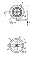
- a cross-shaped recess is formed, which consists of two strip-shaped grooves 8, which intersect at right angles. These grooves 8 run with a slight inclination to the central crossing area, which forms the deepest point and is referred to as a recess 5, in which engages the free end of the riser pipe 3.
- the intersecting strip-shaped grooves 8 surrounding floor areas are with substantially vertical Wall sections that are rounded at the top, over the recessed areas on.
- the invention is not limited to this preferred embodiment.
- the bottom of the rim of the bottle could sink slightly towards the center, wherein in the central region of the bottom under the riser a trough-shaped depression may be formed, the z. B. has a circular shape in the supervision.
Landscapes
- Containers And Packaging Bodies Having A Special Means To Remove Contents (AREA)
Abstract
Description
- Die Erfindung betrifft einen Behälter mit einer Pumpe, die mit einem Steigrohr verbunden ist, das in den Behälter eingreift, um Behälterinhalt anzusaugen und aus dem Behälter ab zu geben.
- Bei dem Behälter handelt es sich vorzugsweise um eine Flasche mit einem Flaschenhals, ohne dass die Erfindung jedoch auf diese Behälterform beschränkt ist. Der Behälter ist vorzugsweise zur Aufnahme einer Flüssigkeit bestimmt, wobei der Behälterinhalt aber auch eine cremige Substanz sein kann. In einer besonders bevorzugten Ausführungsform ist der Behälter ein kleines Fläschchen zur Abgabe von Augen- und Nasentropfen.
- Bei Behältern, bei denen der Inhalt durch Betätigung einer atmosphärischen Pumpe durch ein Steigrohr angesaugt wird, besteht das Problem, dass eine Restmenge in dem Behälter verbleibt, die mittels der Pumpe nicht ausgebracht werden kann. Der vorliegenden Erfindung liegt die Aufgabe zugrunde, eine Anordnung aus Behälter mit Pumpe und Steigrohr so auszubilden, dass diese Restmenge kleiner ist, als dies bei herkömmlichen Behältern der Fall ist.
- Diese Aufgabe wird erfindungsgemäß durch die Merkmale des Patentanspruchs 1 gelöst.
- Vorteilhafte Ausgestaltungen der Erfindung sind in den Unteransprüchen gekennzeichnet.
- Die Erfindung sieht vor, dass am Behälterboden wenigstens ein vertiefter Bereich ausgebildet ist, und dass das Steigrohr eine solche Länge hat, dass sein freies Ende in den vertieften Bereich eingreift.
- Dabei ist bevorzugt, dass zwischen dem freien Ende des Steigrohrs und dem Boden des vertieften Bereichs ein kleiner Abstand verbleibt, der in der Größenordnung von einigen zehntel Millimeter bis 1 bis 2 mm beträgt, ohne dass die Erfindung auf diese Abmessungen beschränkt ist.
- Dabei liegt es aber auch im Rahmen der Erfindung, dass das Steigrohr mit seinem freien Ende auf dem Boden des vertieften Bereichs aufruht, wobei dann sicher zu stellen ist, dass die Flüssigkeit im ausreichenden Maße in das Steigrohr eintreten kann. Hierzu kann das untere Ende des Steigrohrs abgeschrägt sein.
- In dem vertieften Bereich sammelt sich die Restflüssigkeit, wenn nahezu der gesamte Behälterinhalt abgegeben worden ist, so dass das Steigrohr diese Restmenge fast vollständig aus dem vertieften Bereich ansaugen kann. Zahlreiche Versuche haben ergeben, dass durch diese Ausbildung die im Behälter verbleibende, nicht auszubringende Restflüssigkeit nur einen Bruchteil der in einem herkömmlichen Behälter zurück bleibenden Flüssigkeitsmenge beträgt.
- Der vertiefte Bereich des Behälterbodens befindet sich vorteilhafterweise in der Mitte des Behälterbodens, derart, dass das Steigrohr geradlinig von der Saugseite der Pumpe bis in den vertieften Bereich verläuft.
- In einer vorteilhaften Ausgestaltung der Erfindung hat der vertiefte Bereich des Bodens eine Kreuzform. Dies bedeutet, dass sich zwei streifenförmige Vertiefungen im Behälterboden kreuzen, wobei die streifenförmigen Vertiefungen auch als Rinnen betrachtet werden können, in denen die Restflüssigkeit zum mittigen Kreuzungsbereich fließt, in den das freie Ende des Steigrohrs eingreift. Die streifenförmigen Rinnen laufen schräg zur muldenförmigen Mitte, dem tiefsten Punkt des Behälterbodens. Es liegt aber auch im Rahmen der Erfindung, dass der vertiefte Bereich in der Mitte des Bodens liegt und eine Kreisform oder die Form eines Vierecks oder Mehrecks hat. Dabei ist bevorzugt, dass der umgebende Boden des Behälters leicht schräg zu dem vertieften Bereich hin verläuft, damit sich die Restflüssigkeit in der Vertiefung ansammeln kann.
- Weiter wird mit Vorteil vorgeschlagen, dass der vertiefte Bereich von im wesentlichen senkrechten Wandabschnitten begrenzt ist, ohne dass die Erfindung hierauf beschränkt ist. Diese Wandabschnitte stellen sicher, dass das freie Ende des Steigrohrs, das in seiner Länge auf die Abmessungen des Behälters abgestimmt ist, in dem vertieften Bereich gefangen ist.
- Der Behälter besteht vorteilhafterweise aus Kunststoff und kann z.B. im Extrusionsblasverfahren hergestellt sein, ohne dass die Erfindung auf dieses Material und das genannte Herstellungsverfahren beschränkt ist.
- Mit der Erfindung wird erreicht, dass die in dem Behälter zurückbleibende Restflüssigkeit beträchtlich reduziert wird. Da der vertiefte Bereich an einer solchen Stelle ausgebildet ist, dass das Steigrohr einen gradlinigen Verlauf hat und in dem vertieften Bereich gehalten ist, kann der Behälterinhalt völlig ungehindert durch das Steigrohr angesaugt und ausgebracht werden. Sollte das Steigrohr eine kleine Überlänge haben und mit seinem freien Ende auf dem Boden des vertieften Bereichs aufruhen und sich dabei - gefangen in dem vertieften Bereich - leicht seitlich ausbiegen, beeinträchtigt dies aber nicht die Funktionsfähigkeit und die Fähigkeit, den gesamten Behälterinhalt bis auf eine vernachlässigbar kleine Restmenge auszubringen.
- Weitere Einzelheiten der Erfindung ergeben sich aus der nachfolgenden Beschreibung einer bevorzugten Ausführungsform sowie anhand der Zeichnungen. Dabei zeigen:
- Figur 1
- einen Längsschnitt durch eine erfindungsgemäße Flasche mit Pumpe und Steigrohr;
- Figur 2
- eine vergrößerte Darstellung des Bodenbereichs der
Figur 1 ; - Figur 3
- die Flasche gemäß
Figur 1 teilweise im Längsschnitt und teilweise in einer Seitenansicht; - Figur 4
- eine Aufsicht auf die Flasche gemäß
Figur 3 und - Figur 5
- eine Aufsicht auf den Boden der Flasche.
-
Figur 1 zeigt das komplette System, das im wesentlichen aus einem Behälter 1, einer insgesamt mit dem Bezugszeichen 2 bezeichneten atmosphärischen Pumpe, deren Einzelheiten hier nicht von Interesse sind, und einem Steigrohr 3 besteht, das auf bekannte Weise mit der Pumpe verbunden ist. - Das Steigrohr 3 verläuft geradlinig von dem Saugeingang der Pumpe zum Boden 4 des Behälters, der als Rundflasche ausgebildet ist, an deren Flaschenhals die Pumpe 2 befestigt ist.
- Der Boden 4 der Flasche hat eine besondere Bodenkontur mit einer mittigen Vertiefung 5, in die das freie Ende des Steigrohrs 3 so eingreift, dass das Steigrohr 3 in dieser Lage durch umgebende Wandabschnitt 6 des Bodens gefangen ist. Dabei zeigt
Figur 2 , dass das freie Ende des Steigrohres 3 vom Boden der Vertiefung 5 ein wenig beabstandet ist, und zwar um einige wenige zehntel Millimeter. - Die Bodenkontur ist am besten aus den
Figuren 2 und5 ersichtlich. Der die Vertiefung umgebende Bereich 7 des Bodens 4 steigt vom Rand des Bodens aus mit einer geringen Neigung zur Mitte des Bodens hin an, wieFigur 2 deutlich zeigt. In dem Boden ist eine kreuzförmige Vertiefung ausgebildet, die aus zwei streifenförmigen Rinnen 8 besteht, die sich im rechten Winkel kreuzen. Diese Rinnen 8 laufen mit einer geringen Neigung zum mittigen Kreuzungsbereich zu, der die tiefste Stelle bildet und als Vertiefung 5 bezeichnet ist, in die das freie Ende des Steigrohres 3 eingreift. Die die sich kreuzenden streifenförmigen Rinnen 8 umgebenden Bodenbereiche stehen mit im wesentlichen vertikalen Wandabschnitten, die am oberen Rand gerundet sind, über die vertieften Bereiche über. - Bei dieser Ausbildung sammelt sich praktisch die gesamte restliche Flüssigkeitsmenge der Flasche (nachdem nahezu der gesamte Behälterinhalt abgegeben worden ist) in dem vertieften mittigen Bereich 5, da sich auf den schräg zur Mitte ansteigenden Bereichen 7 keine Restmenge der Flüssigkeit dauerhaft ansammeln kann, die statt dessen bei der Handhabung der Flasche in die streifenförmigen Rinnen 8 fließt und sich in deren tiefsten Kreuzungsbereich 5 ansammelt. Von dort kann die Flüssigkeit bis auf eine in der Größe zu vernachlässigende Restmenge von dem Steigrohr angesaugt und aus dem Behälter abgegeben werden.
- Es wird noch einmal betont, dass die Erfindung nicht auf diese bevorzugte Ausführungsform beschränkt ist. Beispielsweise könnte der Boden vom Flaschenrand aus zur Mitte hin leicht absinken, wobei im mittleren Bereich des Bodens unter dem Steigrohr eine muldenförmige Vertiefung ausgebildet sein kann, die z. B. in der Aufsicht eine Kreisform hat.
- Es wird betont, dass die Erfindung nicht auf die beschriebenen und dargestellten Ausführungsformen beschränkt ist. Vielmehr sind alle offenbarten Merkmale auf jede Weise einzeln miteinander kombinierbar.
Claims (9)
- Behälter mit einer Pumpe, die mit einem Steigrohr verbunden ist, das in den Behälter eingreift, um Behälterinhalt anzusaugen und aus dem Behälter abzugeben,
dadurch gekennzeichnet,
dass am Behälterboden (4) wenigstens ein vertiefter Bereich (5) ausgebildet ist und
dass das Steigrohr (3) eine solche Länge hat, dass sein freies Ende in den vertieften Bereich (5) eingreift. - Behälter nach Anspruch 1,
dadurch gekennzeichnet,
dass zwischen dem freien Ende des Steigrohrs (3) und dem Boden des vertieften Bereichs (5) ein kleiner Abstand verbleibt. - Behälter nach Anspruch 1,
dadurch gekennzeichnet,
dass das Steigrohr mit seinem freien Ende auf dem Boden des vertieften Bereichs aufruht. - Behälter nach einem der Ansprüche 1 bis 3,
dadurch gekennzeichnet,
dass der vertiefte Bereich eine Kreuzform hat, die aus zwei sich kreuzenden, streifenförmigen Rinnen (8) gebildet ist. - Behälter nach einem der Ansprüche 1 bis 3,
dadurch gekennzeichnet,
dass der vertiefte Bereich eine kreisförmige Muldenform hat. - Behälter nach einem der Ansprüche 1 bis 3,
dadurch gekennzeichnet,
dass der vertiefte Bereich die Form eines Vier- oder Mehrecks hat. - Behälter nach einem der Ansprüche 1 bis 6,
dadurch gekennzeichnet,
dass der vertiefte Bereich (5) von im wesentlichen senkrechten Wandabschnitten (6) begrenzt ist. - Behälter nach einem der Ansprüche 1 bis 7,
dadurch gekennzeichnet,
dass die die Vertiefung umgebenden Bereiche des Bodens geneigt verlaufen. - Behälter nach einem der Ansprüche 1 bis 8,
dadurch gekennzeichnet,
dass der Behälter aus Kunststoff besteht.
Applications Claiming Priority (1)
| Application Number | Priority Date | Filing Date | Title |
|---|---|---|---|
| DE102007033375.9A DE102007033375B4 (de) | 2007-07-18 | 2007-07-18 | Behälter |
Publications (2)
| Publication Number | Publication Date |
|---|---|
| EP2017011A1 true EP2017011A1 (de) | 2009-01-21 |
| EP2017011B1 EP2017011B1 (de) | 2011-10-26 |
Family
ID=39768535
Family Applications (1)
| Application Number | Title | Priority Date | Filing Date |
|---|---|---|---|
| EP08012178A Active EP2017011B1 (de) | 2007-07-18 | 2008-07-05 | Behälter für einen Pumpspender, dessen Boden einen vertieften Bereich aufweist |
Country Status (4)
| Country | Link |
|---|---|
| EP (1) | EP2017011B1 (de) |
| AT (1) | ATE530259T1 (de) |
| DE (1) | DE102007033375B4 (de) |
| ES (1) | ES2374999T3 (de) |
Cited By (4)
| Publication number | Priority date | Publication date | Assignee | Title |
|---|---|---|---|---|
| EP2737821A1 (de) | 2012-11-30 | 2014-06-04 | Kao Germany GmbH | Flasche für einen Pumpspender und Verwendung einer Flasche |
| CN112203776A (zh) * | 2018-05-30 | 2021-01-08 | 索芙特海尔公司 | 带泵送单元的吸入装置 |
| DE202023104598U1 (de) | 2023-06-28 | 2024-10-02 | Maria Clementine Martin Klosterfrau Vertriebsgesellschaft mit beschränkter Haftung | Zusammensetzung auf Basis von Pflanzenextrakten und Bisabolol |
| WO2025002625A1 (de) | 2023-06-28 | 2025-01-02 | Maria Clementine Martin Klosterfrau Vertriebsgesellschaft Mbh | Zusammensetzung auf basis von pflanzenextrakten und bisabolol |
Citations (10)
| Publication number | Priority date | Publication date | Assignee | Title |
|---|---|---|---|---|
| EP0499537A1 (de) | 1991-02-14 | 1992-08-19 | Societe Technique De Pulverisation (S.T.E.P.) | Vorrichtung zur Zerstäubung oder Abgabe eines flüssigen Produktes mit einem Schiebesteigrohr im Saugrohr |
| WO1998008616A1 (en) | 1996-08-26 | 1998-03-05 | Dispray S.A. | Micropump with trigger holding device |
| WO2001062626A1 (fr) | 2000-02-21 | 2001-08-30 | Mariko Inoue | Flacon avec dispositif entonnoir |
| US20050092777A1 (en) | 2003-11-03 | 2005-05-05 | Yu-Fa Wu | Container with a draw device |
| EP1621255A1 (de) | 2004-04-30 | 2006-02-01 | Goizper, S. Coop. | Manuelle spritzvorrichtung für gartenbau- und andere zwecke |
| DE60206036T2 (de) | 2001-01-12 | 2006-06-22 | Cebal Aerosol France | Behälter zur vollständigen entleerung von konstanten produktmengen |
| US20060144868A1 (en) | 2006-03-30 | 2006-07-06 | Michael Brisbois | Polymeric container and method of manufacturing the container |
| CA2506145A1 (en) | 2005-04-28 | 2006-10-28 | David Robertson | Pump bottle flow control apparatus |
| US20070181605A1 (en) | 2006-02-06 | 2007-08-09 | Yang David U | Fluid dispenser for minimizing residual fluid content |
| US20080023499A1 (en) | 2006-07-27 | 2008-01-31 | Knight John B | Dispensing package and methods of using and making |
Family Cites Families (3)
| Publication number | Priority date | Publication date | Assignee | Title |
|---|---|---|---|---|
| US3409181A (en) * | 1966-07-18 | 1968-11-05 | Lehmann Kenneth G | Squeeze bottle dispenser |
| WO2001089984A1 (en) * | 2000-05-23 | 2001-11-29 | Carter-Wallace, Inc. | Dispensing container |
| US20060186144A1 (en) * | 2005-02-18 | 2006-08-24 | Tinsley Michael R | Sure shot system |
-
2007
- 2007-07-18 DE DE102007033375.9A patent/DE102007033375B4/de active Active
-
2008
- 2008-07-05 EP EP08012178A patent/EP2017011B1/de active Active
- 2008-07-05 ES ES08012178T patent/ES2374999T3/es active Active
- 2008-07-05 AT AT08012178T patent/ATE530259T1/de active
Patent Citations (10)
| Publication number | Priority date | Publication date | Assignee | Title |
|---|---|---|---|---|
| EP0499537A1 (de) | 1991-02-14 | 1992-08-19 | Societe Technique De Pulverisation (S.T.E.P.) | Vorrichtung zur Zerstäubung oder Abgabe eines flüssigen Produktes mit einem Schiebesteigrohr im Saugrohr |
| WO1998008616A1 (en) | 1996-08-26 | 1998-03-05 | Dispray S.A. | Micropump with trigger holding device |
| WO2001062626A1 (fr) | 2000-02-21 | 2001-08-30 | Mariko Inoue | Flacon avec dispositif entonnoir |
| DE60206036T2 (de) | 2001-01-12 | 2006-06-22 | Cebal Aerosol France | Behälter zur vollständigen entleerung von konstanten produktmengen |
| US20050092777A1 (en) | 2003-11-03 | 2005-05-05 | Yu-Fa Wu | Container with a draw device |
| EP1621255A1 (de) | 2004-04-30 | 2006-02-01 | Goizper, S. Coop. | Manuelle spritzvorrichtung für gartenbau- und andere zwecke |
| CA2506145A1 (en) | 2005-04-28 | 2006-10-28 | David Robertson | Pump bottle flow control apparatus |
| US20070181605A1 (en) | 2006-02-06 | 2007-08-09 | Yang David U | Fluid dispenser for minimizing residual fluid content |
| US20060144868A1 (en) | 2006-03-30 | 2006-07-06 | Michael Brisbois | Polymeric container and method of manufacturing the container |
| US20080023499A1 (en) | 2006-07-27 | 2008-01-31 | Knight John B | Dispensing package and methods of using and making |
Cited By (5)
| Publication number | Priority date | Publication date | Assignee | Title |
|---|---|---|---|---|
| EP2737821A1 (de) | 2012-11-30 | 2014-06-04 | Kao Germany GmbH | Flasche für einen Pumpspender und Verwendung einer Flasche |
| CN112203776A (zh) * | 2018-05-30 | 2021-01-08 | 索芙特海尔公司 | 带泵送单元的吸入装置 |
| DE202023104598U1 (de) | 2023-06-28 | 2024-10-02 | Maria Clementine Martin Klosterfrau Vertriebsgesellschaft mit beschränkter Haftung | Zusammensetzung auf Basis von Pflanzenextrakten und Bisabolol |
| DE102023121682A1 (de) | 2023-06-28 | 2025-01-02 | Maria Clementine Martin Klosterfrau Vertriebsgesellschaft mit beschränkter Haftung | Zusammensetzung auf Basis von Pflanzenextrakten und Bisabolol |
| WO2025002625A1 (de) | 2023-06-28 | 2025-01-02 | Maria Clementine Martin Klosterfrau Vertriebsgesellschaft Mbh | Zusammensetzung auf basis von pflanzenextrakten und bisabolol |
Also Published As
| Publication number | Publication date |
|---|---|
| DE102007033375B4 (de) | 2014-10-30 |
| DE102007033375A1 (de) | 2009-01-29 |
| EP2017011B1 (de) | 2011-10-26 |
| ES2374999T3 (es) | 2012-02-23 |
| ATE530259T1 (de) | 2011-11-15 |
Similar Documents
| Publication | Publication Date | Title |
|---|---|---|
| DE69723198T2 (de) | Spritze mit einem luer-lock Teil | |
| EP2501622B1 (de) | Einsatz für einen transportbehälter aus kunststoff | |
| DE102007050061B4 (de) | Tray | |
| DE202008012290U1 (de) | Kunststoffbehältnis | |
| EP2017011A1 (de) | Behälter für einen Pumpspender, dessen Boden einen vertieften Bereich aufweist | |
| WO1996026321A1 (de) | Bake mit fuss als leiteinrichtung für den strassenverkehr | |
| WO2022136609A1 (de) | Pumpspender | |
| DE102010032008A1 (de) | Flaschenregal | |
| CH435556A (de) | Tropfeinsatz für einen Behälter | |
| DE602006000056T2 (de) | Solevorrichtung | |
| DE102011104971A1 (de) | Einteiliges Funktionselement in der Form eines hohlen Nietelements | |
| WO2017077099A1 (de) | Vorrichtung und verfahren zum ausleiten von objekten mit nicht-rotationssymmetrischer standfläche | |
| DE202025104040U1 (de) | Oberholm und/oder Handlauf, Geländer und Stadion | |
| DE202004015494U1 (de) | Blumenkasten mit Untersetzer, insbesondere aus Kunststoff | |
| DE202010006233U1 (de) | Adapterkonsole für den Einsatz eines rechteckigen Transportkorbs als Spülkorb für Gläser und Geschirr | |
| EP2778089B1 (de) | Stapelbarer Becher | |
| DE102004018141B3 (de) | Haltevorrichtung für Gläser | |
| EP2832341B1 (de) | Arzneimittelflasche | |
| DE3333164C2 (de) | Vorrichtung zum Steuern des Druckes in einem Druckmittel | |
| DE8508928U1 (de) | Auslaufrohr für eine Flüssigkeit | |
| DE102022117467A1 (de) | Scheibenwelle für eine Auf- und/oder Abgabevorrichtung | |
| DE202025001090U1 (de) | Ablagevorrichtung | |
| DE202011000364U1 (de) | Strömungsteilerelement für einen Mixbecher | |
| DE102009021295A1 (de) | Flaschenzelle mit Auskleidung für eine Reinigungsmaschine | |
| DE202008014281U1 (de) | Kunststoffflasche |
Legal Events
| Date | Code | Title | Description |
|---|---|---|---|
| PUAI | Public reference made under article 153(3) epc to a published international application that has entered the european phase |
Free format text: ORIGINAL CODE: 0009012 |
|
| AK | Designated contracting states |
Kind code of ref document: A1 Designated state(s): AT BE BG CH CY CZ DE DK EE ES FI FR GB GR HR HU IE IS IT LI LT LU LV MC MT NL NO PL PT RO SE SI SK TR |
|
| AX | Request for extension of the european patent |
Extension state: AL BA MK RS |
|
| 17P | Request for examination filed |
Effective date: 20090629 |
|
| 17Q | First examination report despatched |
Effective date: 20090731 |
|
| AKX | Designation fees paid |
Designated state(s): AT BE BG CH CY CZ DE DK EE ES FI FR GB GR HR HU IE IS IT LI LT LU LV MC MT NL NO PL PT RO SE SI SK TR |
|
| GRAP | Despatch of communication of intention to grant a patent |
Free format text: ORIGINAL CODE: EPIDOSNIGR1 |
|
| RTI1 | Title (correction) |
Free format text: CONTAINER FOR A PUMP DISPENSER WHOSE BOTTOM COMPRISES A RECESS |
|
| GRAS | Grant fee paid |
Free format text: ORIGINAL CODE: EPIDOSNIGR3 |
|
| GRAA | (expected) grant |
Free format text: ORIGINAL CODE: 0009210 |
|
| AK | Designated contracting states |
Kind code of ref document: B1 Designated state(s): AT BE BG CH CY CZ DE DK EE ES FI FR GB GR HR HU IE IS IT LI LT LU LV MC MT NL NO PL PT RO SE SI SK TR |
|
| REG | Reference to a national code |
Ref country code: GB Ref legal event code: FG4D Free format text: NOT ENGLISH |
|
| REG | Reference to a national code |
Ref country code: CH Ref legal event code: EP |
|
| REG | Reference to a national code |
Ref country code: IE Ref legal event code: FG4D |
|
| REG | Reference to a national code |
Ref country code: CH Ref legal event code: NV Representative=s name: KIRKER & CIE S.A. |
|
| REG | Reference to a national code |
Ref country code: DE Ref legal event code: R096 Ref document number: 502008005320 Country of ref document: DE Effective date: 20120119 |
|
| REG | Reference to a national code |
Ref country code: SE Ref legal event code: TRGR |
|
| REG | Reference to a national code |
Ref country code: NL Ref legal event code: VDEP Effective date: 20111026 |
|
| REG | Reference to a national code |
Ref country code: ES Ref legal event code: FG2A Ref document number: 2374999 Country of ref document: ES Kind code of ref document: T3 Effective date: 20120223 |
|
| LTIE | Lt: invalidation of european patent or patent extension |
Effective date: 20111026 |
|
| PG25 | Lapsed in a contracting state [announced via postgrant information from national office to epo] |
Ref country code: NO Free format text: LAPSE BECAUSE OF FAILURE TO SUBMIT A TRANSLATION OF THE DESCRIPTION OR TO PAY THE FEE WITHIN THE PRESCRIBED TIME-LIMIT Effective date: 20120126 Ref country code: LT Free format text: LAPSE BECAUSE OF FAILURE TO SUBMIT A TRANSLATION OF THE DESCRIPTION OR TO PAY THE FEE WITHIN THE PRESCRIBED TIME-LIMIT Effective date: 20111026 Ref country code: IS Free format text: LAPSE BECAUSE OF FAILURE TO SUBMIT A TRANSLATION OF THE DESCRIPTION OR TO PAY THE FEE WITHIN THE PRESCRIBED TIME-LIMIT Effective date: 20120226 |
|
| PG25 | Lapsed in a contracting state [announced via postgrant information from national office to epo] |
Ref country code: HR Free format text: LAPSE BECAUSE OF FAILURE TO SUBMIT A TRANSLATION OF THE DESCRIPTION OR TO PAY THE FEE WITHIN THE PRESCRIBED TIME-LIMIT Effective date: 20111026 Ref country code: GR Free format text: LAPSE BECAUSE OF FAILURE TO SUBMIT A TRANSLATION OF THE DESCRIPTION OR TO PAY THE FEE WITHIN THE PRESCRIBED TIME-LIMIT Effective date: 20120127 Ref country code: PL Free format text: LAPSE BECAUSE OF FAILURE TO SUBMIT A TRANSLATION OF THE DESCRIPTION OR TO PAY THE FEE WITHIN THE PRESCRIBED TIME-LIMIT Effective date: 20111026 Ref country code: NL Free format text: LAPSE BECAUSE OF FAILURE TO SUBMIT A TRANSLATION OF THE DESCRIPTION OR TO PAY THE FEE WITHIN THE PRESCRIBED TIME-LIMIT Effective date: 20111026 Ref country code: LV Free format text: LAPSE BECAUSE OF FAILURE TO SUBMIT A TRANSLATION OF THE DESCRIPTION OR TO PAY THE FEE WITHIN THE PRESCRIBED TIME-LIMIT Effective date: 20111026 Ref country code: PT Free format text: LAPSE BECAUSE OF FAILURE TO SUBMIT A TRANSLATION OF THE DESCRIPTION OR TO PAY THE FEE WITHIN THE PRESCRIBED TIME-LIMIT Effective date: 20120227 Ref country code: SI Free format text: LAPSE BECAUSE OF FAILURE TO SUBMIT A TRANSLATION OF THE DESCRIPTION OR TO PAY THE FEE WITHIN THE PRESCRIBED TIME-LIMIT Effective date: 20111026 |
|
| REG | Reference to a national code |
Ref country code: IE Ref legal event code: FD4D |
|
| PG25 | Lapsed in a contracting state [announced via postgrant information from national office to epo] |
Ref country code: CY Free format text: LAPSE BECAUSE OF FAILURE TO SUBMIT A TRANSLATION OF THE DESCRIPTION OR TO PAY THE FEE WITHIN THE PRESCRIBED TIME-LIMIT Effective date: 20111026 |
|
| PG25 | Lapsed in a contracting state [announced via postgrant information from national office to epo] |
Ref country code: IE Free format text: LAPSE BECAUSE OF FAILURE TO SUBMIT A TRANSLATION OF THE DESCRIPTION OR TO PAY THE FEE WITHIN THE PRESCRIBED TIME-LIMIT Effective date: 20111026 Ref country code: CZ Free format text: LAPSE BECAUSE OF FAILURE TO SUBMIT A TRANSLATION OF THE DESCRIPTION OR TO PAY THE FEE WITHIN THE PRESCRIBED TIME-LIMIT Effective date: 20111026 Ref country code: DK Free format text: LAPSE BECAUSE OF FAILURE TO SUBMIT A TRANSLATION OF THE DESCRIPTION OR TO PAY THE FEE WITHIN THE PRESCRIBED TIME-LIMIT Effective date: 20111026 Ref country code: EE Free format text: LAPSE BECAUSE OF FAILURE TO SUBMIT A TRANSLATION OF THE DESCRIPTION OR TO PAY THE FEE WITHIN THE PRESCRIBED TIME-LIMIT Effective date: 20111026 Ref country code: SK Free format text: LAPSE BECAUSE OF FAILURE TO SUBMIT A TRANSLATION OF THE DESCRIPTION OR TO PAY THE FEE WITHIN THE PRESCRIBED TIME-LIMIT Effective date: 20111026 Ref country code: BG Free format text: LAPSE BECAUSE OF FAILURE TO SUBMIT A TRANSLATION OF THE DESCRIPTION OR TO PAY THE FEE WITHIN THE PRESCRIBED TIME-LIMIT Effective date: 20120126 |
|
| PG25 | Lapsed in a contracting state [announced via postgrant information from national office to epo] |
Ref country code: RO Free format text: LAPSE BECAUSE OF FAILURE TO SUBMIT A TRANSLATION OF THE DESCRIPTION OR TO PAY THE FEE WITHIN THE PRESCRIBED TIME-LIMIT Effective date: 20111026 |
|
| PLBE | No opposition filed within time limit |
Free format text: ORIGINAL CODE: 0009261 |
|
| STAA | Information on the status of an ep patent application or granted ep patent |
Free format text: STATUS: NO OPPOSITION FILED WITHIN TIME LIMIT |
|
| 26N | No opposition filed |
Effective date: 20120727 |
|
| REG | Reference to a national code |
Ref country code: DE Ref legal event code: R097 Ref document number: 502008005320 Country of ref document: DE Effective date: 20120727 |
|
| BERE | Be: lapsed |
Owner name: GAPLAST G.M.B.H. Effective date: 20120731 |
|
| PG25 | Lapsed in a contracting state [announced via postgrant information from national office to epo] |
Ref country code: MC Free format text: LAPSE BECAUSE OF NON-PAYMENT OF DUE FEES Effective date: 20120731 |
|
| PG25 | Lapsed in a contracting state [announced via postgrant information from national office to epo] |
Ref country code: BE Free format text: LAPSE BECAUSE OF NON-PAYMENT OF DUE FEES Effective date: 20120731 |
|
| PG25 | Lapsed in a contracting state [announced via postgrant information from national office to epo] |
Ref country code: FI Free format text: LAPSE BECAUSE OF FAILURE TO SUBMIT A TRANSLATION OF THE DESCRIPTION OR TO PAY THE FEE WITHIN THE PRESCRIBED TIME-LIMIT Effective date: 20111026 |
|
| PG25 | Lapsed in a contracting state [announced via postgrant information from national office to epo] |
Ref country code: MT Free format text: LAPSE BECAUSE OF FAILURE TO SUBMIT A TRANSLATION OF THE DESCRIPTION OR TO PAY THE FEE WITHIN THE PRESCRIBED TIME-LIMIT Effective date: 20111026 |
|
| PG25 | Lapsed in a contracting state [announced via postgrant information from national office to epo] |
Ref country code: TR Free format text: LAPSE BECAUSE OF FAILURE TO SUBMIT A TRANSLATION OF THE DESCRIPTION OR TO PAY THE FEE WITHIN THE PRESCRIBED TIME-LIMIT Effective date: 20111026 |
|
| PG25 | Lapsed in a contracting state [announced via postgrant information from national office to epo] |
Ref country code: LU Free format text: LAPSE BECAUSE OF NON-PAYMENT OF DUE FEES Effective date: 20120705 |
|
| PG25 | Lapsed in a contracting state [announced via postgrant information from national office to epo] |
Ref country code: HU Free format text: LAPSE BECAUSE OF FAILURE TO SUBMIT A TRANSLATION OF THE DESCRIPTION OR TO PAY THE FEE WITHIN THE PRESCRIBED TIME-LIMIT Effective date: 20080705 |
|
| REG | Reference to a national code |
Ref country code: FR Ref legal event code: PLFP Year of fee payment: 9 |
|
| REG | Reference to a national code |
Ref country code: FR Ref legal event code: PLFP Year of fee payment: 10 |
|
| REG | Reference to a national code |
Ref country code: FR Ref legal event code: PLFP Year of fee payment: 11 |
|
| P01 | Opt-out of the competence of the unified patent court (upc) registered |
Effective date: 20230512 |
|
| PGFP | Annual fee paid to national office [announced via postgrant information from national office to epo] |
Ref country code: GB Payment date: 20240613 Year of fee payment: 17 |
|
| PGFP | Annual fee paid to national office [announced via postgrant information from national office to epo] |
Ref country code: FR Payment date: 20240619 Year of fee payment: 17 |
|
| PGFP | Annual fee paid to national office [announced via postgrant information from national office to epo] |
Ref country code: CH Payment date: 20240801 Year of fee payment: 17 Ref country code: ES Payment date: 20240801 Year of fee payment: 17 |
|
| PGFP | Annual fee paid to national office [announced via postgrant information from national office to epo] |
Ref country code: AT Payment date: 20240726 Year of fee payment: 17 |
|
| PGFP | Annual fee paid to national office [announced via postgrant information from national office to epo] |
Ref country code: IT Payment date: 20240731 Year of fee payment: 17 Ref country code: SE Payment date: 20240723 Year of fee payment: 17 |
|
| PGFP | Annual fee paid to national office [announced via postgrant information from national office to epo] |
Ref country code: DE Payment date: 20250916 Year of fee payment: 18 |
|
| REG | Reference to a national code |
Ref country code: CH Ref legal event code: H13 Free format text: ST27 STATUS EVENT CODE: U-0-0-H10-H13 (AS PROVIDED BY THE NATIONAL OFFICE) Effective date: 20260224 |
|
| REG | Reference to a national code |
Ref country code: AT Ref legal event code: MM01 Ref document number: 530259 Country of ref document: AT Kind code of ref document: T Effective date: 20250705 |
|
| GBPC | Gb: european patent ceased through non-payment of renewal fee |
Effective date: 20250705 |
|
| PG25 | Lapsed in a contracting state [announced via postgrant information from national office to epo] |
Ref country code: GB Free format text: LAPSE BECAUSE OF NON-PAYMENT OF DUE FEES Effective date: 20250705 |
|
| PG25 | Lapsed in a contracting state [announced via postgrant information from national office to epo] |
Ref country code: AT Free format text: LAPSE BECAUSE OF NON-PAYMENT OF DUE FEES Effective date: 20250705 |
|
| PG25 | Lapsed in a contracting state [announced via postgrant information from national office to epo] |
Ref country code: FR Free format text: LAPSE BECAUSE OF NON-PAYMENT OF DUE FEES Effective date: 20250731 |
|
| PG25 | Lapsed in a contracting state [announced via postgrant information from national office to epo] |
Ref country code: CH Free format text: LAPSE BECAUSE OF NON-PAYMENT OF DUE FEES Effective date: 20250731 |