EP2016921A2 - Dispositif de trépied et trépied pour un instrument médical optique - Google Patents
Dispositif de trépied et trépied pour un instrument médical optique Download PDFInfo
- Publication number
- EP2016921A2 EP2016921A2 EP08075643A EP08075643A EP2016921A2 EP 2016921 A2 EP2016921 A2 EP 2016921A2 EP 08075643 A EP08075643 A EP 08075643A EP 08075643 A EP08075643 A EP 08075643A EP 2016921 A2 EP2016921 A2 EP 2016921A2
- Authority
- EP
- European Patent Office
- Prior art keywords
- stand
- vibration
- link
- medical
- tripod
- Prior art date
- Legal status (The legal status is an assumption and is not a legal conclusion. Google has not performed a legal analysis and makes no representation as to the accuracy of the status listed.)
- Withdrawn
Links
Images


Classifications
-
- G—PHYSICS
- G02—OPTICS
- G02B—OPTICAL ELEMENTS, SYSTEMS OR APPARATUS
- G02B7/00—Mountings, adjusting means, or light-tight connections, for optical elements
- G02B7/001—Counterbalanced structures, e.g. surgical microscopes
-
- A—HUMAN NECESSITIES
- A61—MEDICAL OR VETERINARY SCIENCE; HYGIENE
- A61B—DIAGNOSIS; SURGERY; IDENTIFICATION
- A61B90/00—Instruments, implements or accessories specially adapted for surgery or diagnosis and not covered by any of the groups A61B1/00 - A61B50/00, e.g. for luxation treatment or for protecting wound edges
- A61B90/50—Supports for surgical instruments, e.g. articulated arms
-
- A—HUMAN NECESSITIES
- A61—MEDICAL OR VETERINARY SCIENCE; HYGIENE
- A61B—DIAGNOSIS; SURGERY; IDENTIFICATION
- A61B34/00—Computer-aided surgery; Manipulators or robots specially adapted for use in surgery
- A61B34/20—Surgical navigation systems; Devices for tracking or guiding surgical instruments, e.g. for frameless stereotaxis
- A61B2034/2046—Tracking techniques
- A61B2034/2048—Tracking techniques using an accelerometer or inertia sensor
-
- A—HUMAN NECESSITIES
- A61—MEDICAL OR VETERINARY SCIENCE; HYGIENE
- A61B—DIAGNOSIS; SURGERY; IDENTIFICATION
- A61B90/00—Instruments, implements or accessories specially adapted for surgery or diagnosis and not covered by any of the groups A61B1/00 - A61B50/00, e.g. for luxation treatment or for protecting wound edges
- A61B90/50—Supports for surgical instruments, e.g. articulated arms
- A61B2090/5025—Supports for surgical instruments, e.g. articulated arms with a counter-balancing mechanism
- A61B2090/504—Supports for surgical instruments, e.g. articulated arms with a counter-balancing mechanism with a counterweight
-
- A—HUMAN NECESSITIES
- A61—MEDICAL OR VETERINARY SCIENCE; HYGIENE
- A61B—DIAGNOSIS; SURGERY; IDENTIFICATION
- A61B90/00—Instruments, implements or accessories specially adapted for surgery or diagnosis and not covered by any of the groups A61B1/00 - A61B50/00, e.g. for luxation treatment or for protecting wound edges
- A61B90/50—Supports for surgical instruments, e.g. articulated arms
- A61B2090/506—Supports for surgical instruments, e.g. articulated arms using a parallelogram linkage, e.g. panthograph
-
- A—HUMAN NECESSITIES
- A61—MEDICAL OR VETERINARY SCIENCE; HYGIENE
- A61B—DIAGNOSIS; SURGERY; IDENTIFICATION
- A61B90/00—Instruments, implements or accessories specially adapted for surgery or diagnosis and not covered by any of the groups A61B1/00 - A61B50/00, e.g. for luxation treatment or for protecting wound edges
- A61B90/20—Surgical microscopes characterised by non-optical aspects
Definitions
- the present invention relates to a tripod for a medical-optical instrument with a handlebar assembly having at least one handlebar and an active vibration damping device.
- the invention relates to a tripod assembly with such a tripod, arranged on the handlebar assembly holder for the medical-optical instrument and attached to the holder of the tripod medical-optical instrument.
- a tripod for neurosurgery usually carries a surgical microscope with up to 30x magnification.
- the tripod is only finally stiff and therefore shows some deformation under load.
- To build the tripod infinitely stiff is not technically possible.
- a high stiffness also brings a very high weight with it.
- the finite stiffness makes the tripod a swingable system, i. by impacting or by a small external periodic force, the tripod can be excited to vibrate. If the tripod oscillates, the image quality of the surgical microscope is significantly affected, which in particular has disadvantages in neurosurgical operations.
- the bumping can not be prevented in practice. However, it is possible to keep the settling time of the tripod as small as possible after a kick-off. This is usually done by a suitable damping in the hinges that are part of the tripod.
- the tripod is not merely triggered, but by a Periodic force stimulated, so very little can be done against the induced vibrations. Periodic forces can be caused for example by building vibrations, vibrations of air conditioners or by fans. Especially with ceiling stands, which are mechanically fixed to the ceiling of a building, the susceptibility to vibration is particularly high.
- dampers of a classic design such as rubber buffers, have little effect and may even aggravate the vibrations due to their transmission behavior during periodic excitation under certain circumstances by resonances.
- tripods have been proposed in which an active vibration damping in particular should suppress periodically excited vibrations.
- Microscope stands which include a force applying device for active vibration damping.
- the force applying device is disposed between a vertical support arm and a horizontal support arm or between a vertical support arm and a surgical microscope.
- EP 1 447 700 A2 is a microscope described with a tripod, wherein the microscope and / or the tripod at least one supporting part and a Have vibration compensation device.
- a vibration compensation device is a self-regulating device is used, which controls based on the measurement of vibrations integrated drive elements so that they counteract the vibration in actual time such that the vibration does not lead to a change in position of the outer contours and the critical interfaces on the component.
- Such components are the term ARES components from the article by EJ Breitbach et al .: "Adaptive Structure - Concepts and Prospects" of the Institute of Aeroelesticity and the Institute of Structural Mechanics of the German Aerospace Center, pages 3 to 8 , (Publication date unknown), described.
- ARES stands for Actively Reacting Flexible Structure.
- the ARES devices are in EP 1 447 700 A2 arranged in particular at a potential location of vibration bellies.
- an advantageous tripod for holding a medical-optical instrument and an advantageous tripod assembly comprising a tripod, a holder device for a medical-optical instrument and arranged on the holder medical-optical instrument available to deliver.
- An inventive tripod for a medical-optical instrument which may be designed both as a floor stand and as a ceiling stand, comprises a link assembly with at least one handlebar and an active vibration damping device.
- the active vibration damping device is equipped with at least one vibration sensor for receiving a vibration to be damped and at least one actuator for generating a damping counter vibration.
- the at least one actuator is arranged away from a vibration of the vibration to be damped at the surface of a handlebar and for exerting a force on the handlebar, for example. On the Surface of the handlebar, trained.
- the surface may be an outer surface of the handlebar or, in the case of a hollow handlebar, an inner surface.
- the actuator By arranging the actuator away from a vibration of the vibration to be damped, it is possible to dampen the vibration to be damped by exerting a force on the handlebar, for example on the surface of the handlebar, without the actuator causing a large deflection of the handlebar got to.
- the vibration capability of the stand which has hitherto actually been regarded as a disturbing property, is exploited in order to produce a suitable counter-vibration at the location of the antinode, for example at the free end of a support arm.
- the actuators are arranged in the region of the antinode, ie at the location of the maximum deflection, larger actuator movements are necessary to compensate for the movement in the antinode.
- actuator movements can dampen vibrations when at least one actuator is arranged at or near the point of the handlebar on which the force acting on the handlebar load of the medical-optical instrument, the largest mechanical stress on the surface of the handlebar or the largest bending moment generated in the handlebars. At this point, actuator movements can be particularly effectively coupled to generate a counter-vibration in the handlebars.
- At least two actuators may be present, which are arranged on non-parallel surface regions of the link. This embodiment makes it possible to actively damp vibrations in two mutually perpendicular directions.
- the link of the link assembly is a support arm to which a holder for the medical-optical instrument is to be attached. This tends especially to vibrations, as a rule, a relatively large distance between a Location of the support arm and the free end of the support arm to which the holder is to be attached, is present.
- the actuator for generating the countervibration may comprise a piezoelectric material. It may, for example, be a piezoceramic actuator.
- Piezoceramic actuators come in piezo stack construction, piezo-foil construction and piezo fiber construction and can also be used as such in the tripod according to the invention. Due to their flexibility, piezoceramic actuators are particularly suitable, if they are designed in the piezo-foil construction or in piezo fiber construction, for use in the tripod according to the invention.
- the piezoelectric material may also be a ferroelectric material, such as a ferroelectric plastic such as polyvinylidene fluoride.
- ferroelectric plastics allow a largely free shaping of the actuators and thus an optimal adaptation of the actuator shape to the surface geometry of the handlebar.
- the actuator may also include a magnetic mass oscillator with a magnetically vibratable mass and an electromagnetic exciter for exciting a vibration of the mass. Except as a magnetic solid body which can be excited to vibrate mass of the mass oscillator may be formed as located in a vessel ferromagnetic or magnetorheological fluid.
- a conductive magnetic fluid suitable for use in an actuator is, for example, in US 2007/0114486 A1 described. Reference is made to this document for suitable liquids.
- the vibration of the mass can be easily controlled in its amplitude, frequency and direction by a suitably applied electromagnetic field.
- the use of a liquid as a mass oscillator offers the possibility of generating different geometric oscillations with one and the same oscillator.
- ferrofluids have a very low hysteresis, which is advantageous for the control process.
- the vibration sensor of the active vibration damping device can in particular be an acceleration sensor to be attached to the medical-optical instrument or to the holder of the medical-optical instrument. In particular, if it is attached to the instrument itself, it allows a precise determination of the actual instrument vibration.
- the vibration sensor is a bending sensor or voltage sensor which is arranged at or in the vicinity of a position of a link of the handlebar assembly, at which the load acting on the handlebar of the medical-optical instrument, the largest elastic deformation and thus the largest mechanical surface tension and generates the largest bending moment.
- a vibration generates a clearly measurable deformation, which can be easily determined by means of the bending sensor or the voltage sensor.
- piezoelectric or ferroelectric elements may be considered as bending or stress sensors, which in principle function on the same principle as a piezoelectric actuator or a ferroelectric actuator and may also have a corresponding structure. While deformation is induced by applying an electric field to the actuator, the reverse process is utilized in the bending or stress sensor, namely that deformation of the piezoelectric or ferroelectric element results in a measurable voltage which enables detection of the vibration.
- a tripod assembly according to the invention comprises a tripod according to the invention, a holder for the medical-optical instrument arranged on the steering arrangement and a medical-optical instrument fastened to the holder, which can in particular be a surgical microscope. Due to the advantageous active vibration damping described with reference to the stand, the tripod system according to the invention makes it possible to work with the medical-optical instrument without disturbing vibrations.
- the actuator may also be arranged on a handlebar of the holder, in this context, too can be considered as part of the tripod and its handlebar assembly, even if the holder is usually an independent component.
- FIG. 1 A first embodiment of a tripod system with a tripod 1 according to the invention and a stereo-surgical microscope 3 as a medical-optical instrument is highly schematic in FIG FIG. 1 shown.
- the stand 1 rests on a stand base 5, on the underside of rollers 6 are provided, which allow a method of the tripod.
- the tripod foot 5 also has a foot brake 7.
- a tripod column 9 (or a console) is disposed on the stand base 5 and has a hinge 11, on which a first link 13 a Handlebar assembly 15 is pivotally mounted.
- the tripod column 9 has a rotary joint, not shown in the figure.
- joints 14, 16 are provided, via which a first transverse link 19 and a second control arm 21 are pivotally connected to the first link 13.
- a second link 17 is connected via joints 18, 20, which are located substantially at its two opposite ends, to the first transverse link 19 and the second transverse link 21 such that a hinge assembly 15 is formed in the form of a parallel linkage.
- the first transverse link 19 is extended relative to the second control arm 21 and projects beyond the parallel linkage.
- the joint 14 can be considered as a bearing or bearing joint of the above section.
- a microscope holder 25 via a joint 27 is rotatably and pivotally mounted.
- the microscope holder 25 may either be an independent component or an integral part of the stand 1. On the microscope holder 25, the stereo-surgical microscope 3 is attached.
- balancing weights 29, 31 are arranged on the second link 17 and on the second transverse link 21, which ensure that no resulting torques remain due to the weight of the surgical microscope 3.
- no motors and brakes are basically necessary. Nevertheless, electric motors can be present in the individual joints in order to enable a motor-driven movement of the stand 1.
- the joints may have brakes, with which they can be secured against accidental movement.
- building vibrations can be transmitted to the stand 1 via the wheels 6 and the brake 7, which result in a swinging of the protruding section 23 of the first transverse link 19 designed as a support arm.
- the oscillating mass here is the surgical microscope 3 together with the microscope holder 25 to watch.
- the vibration leads to a deflection in the region of the joint 27, which in turn induces mechanical stresses in the surface of the link 19.
- the stress profile induced by the weight force of the surgical microscope 3 and the holder 25 in the first transverse link 19 is in FIG FIG. 7 outlined.
- the stress ⁇ increases linearly from the joint 27 in the direction of the bearing joint 14 and reaches its maximum value at the bearing joint 14. Starting from bearing joint 14, it then decreases linearly again towards the joint 18.
- the stand 1 is equipped with an active vibration damping system.
- This comprises a vibration sensor 33, which in the present exemplary embodiment is configured as an acceleration sensor to be attached to the surgical microscope 3.
- the device comprises a controller 35 and an actuator arrangement 37.
- An acceleration detected by the acceleration sensor 33 due to a vibration of the surgical microscope 3 is converted into an acceleration signal and forwarded to the controller 35 via a signal line 34.
- a counter-vibration to be generated is determined by means of a suitable control algorithm on the basis of the acceleration signal, which is able to cancel the oscillation of the surgical microscope 3 by destructive interference.
- a control signal is output to the actuator arrangement 37 via the signal line 36.
- the actuating signal causes the actuator arrangement to generate the countervibration in the first transverse link 19 determined by the controller 35.
- the actuator arrangement 37 comprises two piezoceramic elements 39, 41, which are designed as piezo-fiber elements are.
- One of the piezo fiber elements 39 is arranged on the underside of the first cross member 19 immediately in front of the bearing joint 14.
- the second piezo fiber element 41 is likewise arranged directly in front of the bearing joint 14 on the upper side of the first transverse link 19.
- Both piezo fiber elements 39, 41 are fixedly connected to the surface of the first cross member 19 and can thus induce stresses in the surface thereof by contraction and expansion in the longitudinal direction L of the first transverse link 19.
- piezo fiber elements 39, 41 are present, it is basically sufficient to provide a piezo fiber element, provided that the piezo fiber element allows both an expansion and a contraction. However, if the piezo fiber element is merely configured to perform either contraction or expansion, but not both, piezo fiber elements may be disposed on opposite surfaces of the link 19 as shown. Depending on whether the oscillation leads straight up to a deflection of the first cross member up or down, then at least one of the two piezo fiber elements would be activated to compensate for the deflection.
- FIG. 2 A second embodiment of the tripod according to the invention is in FIG. 2 shown.
- the mechanical structure of the tripod does not differ from the mechanical structure of the FIG. 1 shown tripod and is therefore not described again to avoid repetition.
- the difference of in FIG. 2 shown tripod for in FIG. 1 shown tripod is alone in the vibration damping device.
- the vibration damping device comprises in the second embodiment a vibration pickup 133, which is designed as a bending sensor, a controller 135 and an actuator 137.
- the controller 135 is connected via a signal line 134 for receiving a bending signal to the bending sensor 133 and for outputting a control signal via a signal line 136 to the actuator assembly 137.
- the bending signal in this case represents a bending moment caused by the vibration to be damped.
- a piezoelectric element may be used, for example, a piezoelectric ceramic. This is designed to generate an electric voltage when it is bent, the amount of voltage depending on the amount of bending of the piezoelectric sensor 133.
- the resulting due to a force acting on the free end of the first cross member force of bending shows a course that the in FIG. 7 shown course of the surface tensions ⁇ corresponds, ie a maximum at the bearing joint 14 has.
- An oscillation of the surgical microscope 3 therefore generates a maximum bending moment in the region of the bearing joint 14, which is well suited for detecting a vibration.
- the controller 135 calculates a suitable counter-vibration and outputs a control signal representing the counter-vibration to the actuator arrangement 137.
- the actuator arrangement 137 is designed in the form of two stacked piezoelements 139, 141. These are constructed such that, when a suitable voltage is applied, they generate a bending moment in the first transverse link 19, which is opposite to the bending moment generated by the vibration to be damped. In this way, the counter-vibration can be introduced into the first transverse link 19, so that the vibration to be damped is canceled by destructive interference.
- the bending sensor and the piezo elements of the actuator may also be arranged transversely to the longitudinal direction of the link 19 next to each other.
- FIG. 3 shows a third embodiment of a tripod device with a tripod according to the invention 1.
- the tripod 1 corresponds to the two previous embodiments. Its mechanical elements are therefore designated by the same reference numerals as in these two embodiments and will not be explained again to avoid repetition.
- the third embodiment differs from the other two embodiments by its active vibration damping device.
- This comprises a vibration sensor 233 to be attached to the surgical microscope 3, a regulator 235 and an actuator 237, which is not arranged on the arm representing the first arm 19 in the present embodiment, but on a handlebar of the microscope holder 25.
- the vibration sensor 233 is as in the first embodiment as Acceleration sensor formed and connected via a signal line 234 for outputting an acceleration signal representing the microscope acceleration with the controller 235.
- the controller is connected to the actuator 237 via a signal line 236 for outputting an actuating signal.
- the controller 235 includes a control algorithm that determines a suitable counter vibration for attenuating the microscope vibration based on the received acceleration data and outputs a suitable control signal for generating the counter vibration to the actuator 237.
- the actuator 237 then generates the countervibration that results in destructive interference with the vibration to be damped in response to the control signal.
- the actuator 237 used is a mass oscillator which comprises a magnetic mass which can be excited to vibrate and an electromagnetic excitation device with which the magnetic mass can be excited to oscillate.
- the mass swing is in the FIGS. 4a and 4b shown schematically.
- the figures show a section of a hollow handlebar 26 of the microscope holder 25, on the outside of the mass oscillator 237 is attached. But he can alternatively also in the interior of the handlebar 26th be arranged.
- the mass oscillator 237 comprises a container 239 in which a ferromagnetic liquid 240 is located and which is attached to the handlebar 26.
- an electromagnet 241 is attached, with which can generate a magnetic alternating field.
- the ferroelectric liquid 240 is pressed either in the direction of the handlebar 26 ( FIG. 4A ) or in the direction of the electromagnet 241 (FIG. FIG. 4B ).
- a vibration of the liquid 240 in the container 239 can be brought about, which transfers to the handlebar 26.
- the control of the electromagnet is carried out by the controller 235 that the vibration induced in the arm 26 cancels the vibration of the operating microscope 3 to be damped by destructive interference.
- a magnetorheological fluid can also be used, which also reacts to magnetic fields, but changes its viscosity. In contrast, a ferroelectric liquid does not change its viscosity when a magnetic field is applied.
- FIG. 5 A fourth embodiment of the inventive tripod device is in FIG. 5 shown.
- This embodiment corresponds to that with reference to FIG FIG. 1 described embodiment with the difference that it is the tripod 1 is not a ground stand as in the first embodiment, but a ceiling stand. Instead of standing on a tripod stand pillar 9 is arranged hanging from the ceiling. Unwanted vibrations can, for example, be coupled via the ceiling into this stand 1.
- the active vibration damping device fully corresponds to that of the first embodiment.
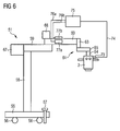
- FIG. 6 A fifth embodiment of a tripod device with a tripod according to the invention is in FIG. 6 shown.
- the tripod 51 is a mobile motor stand with increased stability. It comprises a stand base 55, on the underside of rollers 56 are provided, which allow a method of the stand 51. In order to prevent unintentional movement of the stand 51, the stand base 55 also has a foot brake 57.
- the stand further comprises a height-adjustable as a tripod members Tripod column 58, a support arm 59, a spring arm 60 and a microscope suspension or holder 61, which in turn comprises a connecting element 63, a pivot arm 65 and a support arm 64.
- the microscope holder 61 can also be considered as a stand-alone unit that is not part of the tripod.
- a surgical microscope 3 is attached on the microscope holder 61.
- a light source 66 for object illumination and a power supply unit and an operating element 67 for electrical components of the microscope 3 and the stand 51 are also arranged. Both the lamps and the supply unit can generate vibrations, for example when cooling of these units is necessary. In addition, vibrations can be picked up from the ground via the stand base 55 and the wheels 56, as in the case of a tripod driven by a motor.
- the stand 51 therefore comprises an active vibration damping device with a vibration sensor 73 designed as an acceleration sensor, a controller 57 and two actuators 77a, 77b.
- the regulator 75 is connected to the acceleration sensor 73 for receiving an acceleration signal via a signal line 74 and for outputting actuating signals via two signal lines 76a, 76b to the actuators 77a, 77b.
- Actuators in the present embodiment piezoelectric elements in stack construction in use. These generate upon application of a suitable voltage acting on the spring arm 60 bending moment. When an alternating voltage is applied, a vibration in the spring arm can thus be induced.
- the controller 75 determines the setting signals for the actuators 77a, 77b on the basis of the received acceleration signal such that a counter-vibration to a detected microscope oscillation is generated, which dampens the detected microscope oscillation by way of destructive interference.
- Piezoceramic actuators and an actuator with a magnetic mass oscillator and an electromagnetic excitation device have been used in the exemplary embodiments described.
- other actuators may also be used, for example, ferroelectric actuators.
- Ferroelectric materials form a subset of the piezoelectric materials that are very suitable for manufacturing Precise actuators can be used and is therefore particularly suitable for the manufacture of actuators for damping vibrations in tripods.
- the present invention provides a way to effectively actively dampen vibrations in tripods for medical optical instruments.
- a mechanical counter-tension is generated on the surface of a link, which compensates the resulting from the vibration to be damped mechanical stress, or there is provided a bending moment which compensates the resulting from the vibration to be damped bending moment of the link.
- the actuator of a vibration of the vibration to be damped away on the surface of a handlebar is arranged.
- the actuator is arranged at or in the vicinity of the point with the highest induced by the vibration to be damped bending moment or the largest induced by the vibration to be damped mechanical surface tension in the carrier.
Landscapes
- Health & Medical Sciences (AREA)
- Surgery (AREA)
- Physics & Mathematics (AREA)
- Life Sciences & Earth Sciences (AREA)
- Biomedical Technology (AREA)
- Molecular Biology (AREA)
- Pathology (AREA)
- Nuclear Medicine, Radiotherapy & Molecular Imaging (AREA)
- Optics & Photonics (AREA)
- Engineering & Computer Science (AREA)
- General Physics & Mathematics (AREA)
- Heart & Thoracic Surgery (AREA)
- Medical Informatics (AREA)
- Oral & Maxillofacial Surgery (AREA)
- Animal Behavior & Ethology (AREA)
- General Health & Medical Sciences (AREA)
- Public Health (AREA)
- Veterinary Medicine (AREA)
- Microscoopes, Condenser (AREA)
- Accommodation For Nursing Or Treatment Tables (AREA)
- Vibration Prevention Devices (AREA)
Applications Claiming Priority (1)
| Application Number | Priority Date | Filing Date | Title |
|---|---|---|---|
| DE102007034286A DE102007034286A1 (de) | 2007-07-20 | 2007-07-20 | Stativanordnung und Stativ für ein medizinisch-optisches Instrument |
Publications (2)
| Publication Number | Publication Date |
|---|---|
| EP2016921A2 true EP2016921A2 (fr) | 2009-01-21 |
| EP2016921A3 EP2016921A3 (fr) | 2011-12-21 |
Family
ID=40042582
Family Applications (1)
| Application Number | Title | Priority Date | Filing Date |
|---|---|---|---|
| EP08075643A Withdrawn EP2016921A3 (fr) | 2007-07-20 | 2008-07-17 | Dispositif de trépied et trépied pour un instrument médical optique |
Country Status (4)
| Country | Link |
|---|---|
| US (1) | US20090020666A1 (fr) |
| EP (1) | EP2016921A3 (fr) |
| JP (1) | JP2009028534A (fr) |
| DE (1) | DE102007034286A1 (fr) |
Cited By (2)
| Publication number | Priority date | Publication date | Assignee | Title |
|---|---|---|---|---|
| CN107184281A (zh) * | 2017-06-27 | 2017-09-22 | 苏州卡睿知光电科技有限公司 | 一种手术显微镜 |
| EP3690277A1 (fr) * | 2019-01-11 | 2020-08-05 | The Boeing Company | Couplages qui stabilisent activement les vibrations |
Families Citing this family (12)
| Publication number | Priority date | Publication date | Assignee | Title |
|---|---|---|---|---|
| BRPI1008478A2 (pt) | 2009-02-10 | 2019-09-24 | Nippon Soda Co | compostos contendo nitrogênio e agentes de controle de organismo nocivo |
| DE102010027248A1 (de) | 2010-07-15 | 2012-01-19 | Sensodrive Gmbh | Haltevorrichtung für ein Instrument |
| US8937822B2 (en) * | 2011-05-08 | 2015-01-20 | Paul Wilkinson Dent | Solar energy conversion and utilization system |
| DE102011054087B4 (de) | 2011-09-30 | 2018-08-30 | Carl Zeiss Microscopy Gmbh | Optische Bildstabilisierungsvorrichtung und optisches Beobachtungsgerät |
| DE102012204796A1 (de) * | 2012-03-26 | 2013-09-26 | Carl Zeiss Microscopy Gmbh | Kamerasystem sowie Verfahren zur Kühlung eines Kamerasystems |
| DE102012222345A1 (de) * | 2012-12-05 | 2014-06-05 | Smiths Heimann Gmbh | Röntgenprüfanlage, insbesondere mobile Röntgenprüfanlage für großvolumige Güter |
| CN104605937B (zh) * | 2015-01-21 | 2017-02-01 | 青岛市市立医院 | 神经外科手术显微镜 |
| JP6704255B2 (ja) * | 2016-01-19 | 2020-06-03 | ソニー・オリンパスメディカルソリューションズ株式会社 | 医療用観察装置、医療用観察システム及び画揺れ補正方法 |
| CN109152519A (zh) * | 2016-03-31 | 2019-01-04 | 索尼奥林巴斯医疗解决方案公司 | 医疗观察装置、图像移动校正方法、及医疗观察系统 |
| US10228530B2 (en) * | 2016-09-30 | 2019-03-12 | Mitaka Kohki Co., Ltd. | Stand apparatus for surgical microscope |
| CN113700942B (zh) * | 2021-10-26 | 2022-04-15 | 江苏嘉胜石油科技有限公司 | 一种基于石油管道安装及维修用的支撑底座 |
| CN116736944A (zh) * | 2022-03-01 | 2023-09-12 | 英业达科技有限公司 | 服务器机壳 |
Citations (7)
| Publication number | Priority date | Publication date | Assignee | Title |
|---|---|---|---|---|
| DE4342717A1 (de) | 1992-12-24 | 1994-06-30 | Anschuetz & Co Gmbh | Bildstabilisierungseinrichtung |
| DE4324538A1 (de) | 1993-06-21 | 1994-12-22 | Bittrich Hans Heiner Dr | Nickeltolerante FCC-Katalysatoren |
| US20010002432A1 (en) | 1999-11-29 | 2001-05-31 | Scan-Marl, Inc. | Suction tube for surgical purposes |
| EP1447700A2 (fr) | 2003-02-15 | 2004-08-18 | Leica Microsystems (Schweiz) AG | Microscope avec support et dispositif à compensation de vibrations |
| DE102004004602A1 (de) | 2004-01-29 | 2005-08-18 | Carl Zeiss | Stativvorrichtung für ein medizinisch-optisches Instrument |
| DE102004063606A1 (de) | 2004-02-20 | 2006-07-06 | Carl Zeiss Ag | Haltevorrichtung, insbesondere für ein medizinisch-optisches Instrument, mit einer Einrichtung zur aktiven Schwingungsdämpfung |
| US20070114486A1 (en) | 2005-10-27 | 2007-05-24 | Showa Denko K.K. | Electrically conductive magnetic fluid and use thereof |
Family Cites Families (7)
| Publication number | Priority date | Publication date | Assignee | Title |
|---|---|---|---|---|
| CH687425A5 (de) * | 1992-12-24 | 1996-11-29 | Anschuetz & Co Gmbh | Mikroskop. |
| US6392795B2 (en) * | 1998-08-28 | 2002-05-21 | Olympus Optical Co., Ltd. | Microscope with a dynamic damper |
| US6628457B2 (en) * | 2000-07-11 | 2003-09-30 | Asahi Kogaku Kogyo Kabushiki Kaisha | Antivibration microscope |
| DE10163354A1 (de) * | 2001-12-21 | 2003-07-03 | Leica Microsystems | Vorrichtung zum Halten einer optischen Betrachtungseinrichtung |
| DE10310459A1 (de) * | 2003-03-07 | 2004-09-16 | Carl Zeiss | Stativvorrichtung für ein medizinisch-optisches Instrument |
| US7170250B2 (en) * | 2003-06-30 | 2007-01-30 | Carl Zeiss Surgical Gmbh | Holding arrangement having a device for actively damping vibration |
| US7138747B1 (en) * | 2004-07-29 | 2006-11-21 | Anorad Corporation | Damping and stabilization for linear motor stage |
-
2007
- 2007-07-20 DE DE102007034286A patent/DE102007034286A1/de not_active Withdrawn
-
2008
- 2008-07-17 EP EP08075643A patent/EP2016921A3/fr not_active Withdrawn
- 2008-07-18 JP JP2008187261A patent/JP2009028534A/ja active Pending
- 2008-07-21 US US12/176,446 patent/US20090020666A1/en not_active Abandoned
Patent Citations (7)
| Publication number | Priority date | Publication date | Assignee | Title |
|---|---|---|---|---|
| DE4342717A1 (de) | 1992-12-24 | 1994-06-30 | Anschuetz & Co Gmbh | Bildstabilisierungseinrichtung |
| DE4324538A1 (de) | 1993-06-21 | 1994-12-22 | Bittrich Hans Heiner Dr | Nickeltolerante FCC-Katalysatoren |
| US20010002432A1 (en) | 1999-11-29 | 2001-05-31 | Scan-Marl, Inc. | Suction tube for surgical purposes |
| EP1447700A2 (fr) | 2003-02-15 | 2004-08-18 | Leica Microsystems (Schweiz) AG | Microscope avec support et dispositif à compensation de vibrations |
| DE102004004602A1 (de) | 2004-01-29 | 2005-08-18 | Carl Zeiss | Stativvorrichtung für ein medizinisch-optisches Instrument |
| DE102004063606A1 (de) | 2004-02-20 | 2006-07-06 | Carl Zeiss Ag | Haltevorrichtung, insbesondere für ein medizinisch-optisches Instrument, mit einer Einrichtung zur aktiven Schwingungsdämpfung |
| US20070114486A1 (en) | 2005-10-27 | 2007-05-24 | Showa Denko K.K. | Electrically conductive magnetic fluid and use thereof |
Non-Patent Citations (1)
| Title |
|---|
| E. J. BREITBACH ET AL.: "Adaptive Structure - Concepts and Prospects", pages: 3 - 8 |
Cited By (3)
| Publication number | Priority date | Publication date | Assignee | Title |
|---|---|---|---|---|
| CN107184281A (zh) * | 2017-06-27 | 2017-09-22 | 苏州卡睿知光电科技有限公司 | 一种手术显微镜 |
| EP3690277A1 (fr) * | 2019-01-11 | 2020-08-05 | The Boeing Company | Couplages qui stabilisent activement les vibrations |
| US11028898B2 (en) | 2019-01-11 | 2021-06-08 | The Boeing Company | Couplings that actively stabilize vibrations |
Also Published As
| Publication number | Publication date |
|---|---|
| JP2009028534A (ja) | 2009-02-12 |
| US20090020666A1 (en) | 2009-01-22 |
| EP2016921A3 (fr) | 2011-12-21 |
| DE102007034286A1 (de) | 2009-01-22 |
Similar Documents
| Publication | Publication Date | Title |
|---|---|---|
| EP2016921A2 (fr) | Dispositif de trépied et trépied pour un instrument médical optique | |
| DE102007039548B3 (de) | System und Verfahren zur Schwingungsbeeinflussung | |
| DE112006001416T5 (de) | Systeme und Verfahren zur aktiven Schwingungsdämpfung | |
| DE69408015T2 (de) | Einrichtung zur Regelung von aktiven Lagern | |
| DE102012004808A1 (de) | Vorrichtung zur Beeinflussung der Schwingungsübertragung zwischen zwei Einheiten | |
| EP3158629B1 (fr) | Actionneur linéaire, palier hydraulique et véhicule automobile équipé d'un tel palier hydraulique ou actionneur linéaire | |
| EP2673531B1 (fr) | Montage sans vibrations d'un objet sur une structure | |
| DE102012222988B4 (de) | Mikromechanische Resonatoranordnung | |
| DE112013002833T5 (de) | Aktives Schwingungsisolationssystem | |
| EP1784583A1 (fr) | Dispositif de fixation qui inhibe la transmission de chocs et de vibrations | |
| EP1882112B1 (fr) | Dispositif de decouplage d'oscillations | |
| DE102010027248A1 (de) | Haltevorrichtung für ein Instrument | |
| DE3821368A1 (de) | Schwingungsdaempfende und schwingungskompensierende lageranordnung | |
| DE102012000857B4 (de) | Fernoptische Vorrichtung mit Bildstabilisierung | |
| DE102005003013B3 (de) | Vorrichtung zur dynamischen Belastungsprüfung einer Probe | |
| EP1078176A1 (fr) | Element de transmission pour la transmission de forces et/ou de couples, amortisseur d'oscillations et procede d'amortissement d'oscillations | |
| DE102004003175B3 (de) | Lenksäule | |
| EP0376107B1 (fr) | Téléscope avec stabilisation d'image | |
| DE202010000199U1 (de) | Einstellbare Schwingungstilgervorrichtung für ein Robotersystem | |
| DE102004030935B3 (de) | Vorrichtung zur Schwingungsdämpfung in einem Kraftfahrzeug | |
| DE102010030700A1 (de) | Aktiver Schwingungstilger | |
| EP2706034A1 (fr) | Réducteur actif pour structures oscillantes de basse fréquence | |
| EP1447700B1 (fr) | Microscope chirurgical avec support et dispositif à compensation de vibrations | |
| DE102012000859B4 (de) | Binokulare fernoptische Vorrichtung mit Bildstabilisierung | |
| DE2744680C2 (de) | Korpuskularstrahloptisches Gerät mit einem in mindestens einem Lager sitzenden Objekthalter |
Legal Events
| Date | Code | Title | Description |
|---|---|---|---|
| PUAI | Public reference made under article 153(3) epc to a published international application that has entered the european phase |
Free format text: ORIGINAL CODE: 0009012 |
|
| AK | Designated contracting states |
Kind code of ref document: A2 Designated state(s): AT BE BG CH CY CZ DE DK EE ES FI FR GB GR HR HU IE IS IT LI LT LU LV MC MT NL NO PL PT RO SE SI SK TR |
|
| AX | Request for extension of the european patent |
Extension state: AL BA MK RS |
|
| RAP1 | Party data changed (applicant data changed or rights of an application transferred) |
Owner name: CARL ZEISS MEDITEC AG |
|
| PUAL | Search report despatched |
Free format text: ORIGINAL CODE: 0009013 |
|
| AK | Designated contracting states |
Kind code of ref document: A3 Designated state(s): AT BE BG CH CY CZ DE DK EE ES FI FR GB GR HR HU IE IS IT LI LT LU LV MC MT NL NO PL PT RO SE SI SK TR |
|
| AX | Request for extension of the european patent |
Extension state: AL BA MK RS |
|
| RIC1 | Information provided on ipc code assigned before grant |
Ipc: A61B 19/00 20060101AFI20111111BHEP |
|
| AKX | Designation fees paid |
Designated state(s): DE ES FR GB IT |
|
| STAA | Information on the status of an ep patent application or granted ep patent |
Free format text: STATUS: THE APPLICATION IS DEEMED TO BE WITHDRAWN |
|
| 18D | Application deemed to be withdrawn |
Effective date: 20120622 |