EP2016453B1 - Optische faserverteilungskabel und strukturen dafür - Google Patents
Optische faserverteilungskabel und strukturen dafür Download PDFInfo
- Publication number
- EP2016453B1 EP2016453B1 EP07835759.7A EP07835759A EP2016453B1 EP 2016453 B1 EP2016453 B1 EP 2016453B1 EP 07835759 A EP07835759 A EP 07835759A EP 2016453 B1 EP2016453 B1 EP 2016453B1
- Authority
- EP
- European Patent Office
- Prior art keywords
- distribution
- cable
- optical fiber
- tube
- optical fibers
- Prior art date
- Legal status (The legal status is an assumption and is not a legal conclusion. Google has not performed a legal analysis and makes no representation as to the accuracy of the status listed.)
- Active
Links
Images


Classifications
-
- G—PHYSICS
- G02—OPTICS
- G02B—OPTICAL ELEMENTS, SYSTEMS OR APPARATUS
- G02B6/00—Light guides; Structural details of arrangements comprising light guides and other optical elements, e.g. couplings
- G02B6/44—Mechanical structures for providing tensile strength and external protection for fibres, e.g. optical transmission cables
- G02B6/4439—Auxiliary devices
- G02B6/4471—Terminating devices ; Cable clamps
- G02B6/4472—Manifolds
- G02B6/4475—Manifolds with provision for lateral branching
-
- G—PHYSICS
- G02—OPTICS
- G02B—OPTICAL ELEMENTS, SYSTEMS OR APPARATUS
- G02B6/00—Light guides; Structural details of arrangements comprising light guides and other optical elements, e.g. couplings
- G02B6/44—Mechanical structures for providing tensile strength and external protection for fibres, e.g. optical transmission cables
- G02B6/4439—Auxiliary devices
- G02B6/444—Systems or boxes with surplus lengths
- G02B6/4441—Boxes
- G02B6/44515—Fibre drop terminals with surplus length
Definitions
- the present invention relates generally to fiber optic distribution cables, methods for manufacturing the same, tools, and kits therefor. More particularly, the present invention relates to fiber optic distribution cables, methods of manufacturing the same, tools, and kits for distributing optical fibers toward subscribers such as in optical fiber to the home or curb applications (FTTx).
- FTTx home or curb applications
- Communication networks are used to transport a variety of signals such as voice, video, data transmission, and the like.
- Traditional communication networks use copper wires in cables for transporting information and data.
- copper cables have drawbacks because they are large, heavy, and can only transmit a relatively limited amount of data with a reasonable cable diameter. Consequently, optical fiber cables replaced most of the copper cables in long-haul communication network links, thereby providing greater bandwidth capacity for long-haul links.
- most communication networks still use copper cables for distribution and/or drop links on the subscriber side of the central office. In other words, subscribers have a limited amount of available bandwidth due to the constraints of copper cables in the communication network. Stated another way, the copper cables are a bottleneck that inhibit the subscriber from fully utilizing the relatively high-bandwidth capacity of the optical fiber long-hauls links.
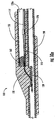
- FIG. 1 depicts a fiber optic cable 10 having a breach B in the cable jacket with a breach length BL. Breach length BL depends on the length of an optical fiber OF required by the craft for the access procedure.
- breach length BL has a slightly longer length such as 35 centimeters for presenting 30 centimeters of optical fiber OF outside the cable jacket. More specifically, the optical fiber desired for distribution is selected and cut near the downstream end of breach B and then arranged to exit the fiber optic cable near the upstream end of breach B, thereby giving the craftsman optical fiber OF with the required length.
- One drawback for this method is that the breach length BL is relatively long and disrupts the protection provided by the cable jacket. Stated another way, breach B must be closed and/or sealed in order to provide proper protection, which requires a relatively large covering that is bulky, cumbersome, and/or stiff. Consequently, the distribution fiber optic cable is too large and/or stiff at the distribution location, thereby making effective routing of the distribution fiber optic cable through sheeves, ducts, or the like during installation difficult, if not impossible.
- FIG. 2 depicts a fiber optic cable 10' with a first cable jacket breach B1 and a second (i.e., downstream) cable jacket breach B2 that are spaced apart by a significant distance D.
- a typical distance D between cable jacket breaches B1,B2 is about thirty centimeters.
- optical fiber OF for distribution must be located twice (once at each jacket breach B 1,B2) and the length of optical fiber OF protruding from the first cable jacket breach B1 is dependent on distance D between cable jacket breaches B1,B2.
- the cable jacket breaches B1,B2 are closed for providing environmental protection such as by overmolding or using a heat shrink tubing.
- the fiber optic distribution cable includes a plurality of optical fibers within a protective covering and a distribution optical fiber.
- the distribution optical fiber is one of the plurality of optical fibers of the fiber optic distribution cable that is presented outward of the protective covering at an access location for distribution toward the subscriber.
- the access location has a length AL and the distribution optical fiber removed from the fiber optic distribution cable has a distribution optical fiber length DOFL, wherein the distribution optical fiber length is about 5/4 AL or more.
- Another aspect of the present invention is directed to a fiber optic distribution cable including a plurality of optical fibers, a protective covering, a distribution optical fiber, and a demarcation point.
- the distribution optical fiber being one of the plurality of optical fibers of the fiber optic distribution cable that is presented outward of the protective covering at an access location.
- the demarcation point being disposed about a portion of the distribution optical fiber for inhibiting the movement of the distribution optical fiber. In other words, the demarcation point inhibits the distribution optical fiber from pistoning into or out of the fiber optic distribution cable.
- Yet another aspect of the present invention is directed to a fiber optic distribution cable including a plurality of optical fibers, a protective covering at least one distribution optical fiber, an indexing tube, and a tether tube.
- the at least one distribution optical fiber is selected from one of optical fibers of the fiber optic distribution cable and protrudes from an access location of the protective covering.
- the tether tube is disposed about a portion of the at least one distribution optical fiber for protecting the at least one distribution optical fiber.
- US 2005/259928 A1 discloses a protective tube that encloses and protects splice-ready fibers or connectors until the optical connection is desired, at which time the protective tube is removed.
- the splice-ready fibers or connectors can not be accessed until the protective tube is removed and is a disposable portion of the cable assembly. There is no excess fiber length within the protective tube since the fiber length is shorter than the protective tube.
- JP 2001 116968 A merely discloses a tube exiting an enclosure.
- US-A-5 210 812 merely discloses a stub cable exiting a branch module.
- a buffer tube of the stub cable passes through the halves of branch module.
- the tether tube is attached at a predetermined position relative to the indexing tube, thereby loading an excess fiber length in the distribution optical fiber.
- steps which may or may not require other components can be performed on the fiber optic distribution cables by the craft. For instance, a transition tube may be slid over the distribution optical fiber for protecting the same.
- the present invention discloses distribution fiber optic cables and methods of making the same where one or more optical fibers of a fiber optic cable are presented outside a protective covering such as a cable jacket for distribution. Additionally, the present invention also discloses tools for the methods of making along with kits of parts useful for making the distribution fiber optic cables.
- a relatively small opening is formed at the access location of the fiber optic cable, thereby leaving a relatively small access footprint (i.e., removing a small portion of the protective covering and/or other cable components) on the fiber optic cable.
- the method advantageously provides a length of distribution optical fiber protruding from the access location that is longer than the opening of the access location.
- the opening in the cable jacket is about 2 centimeters the distribution optical fiber is cut within the distribution cable and has a length of about 2.5 centimeters or more.
- the craft has a suitable length of distribution optical fiber to work with for distribution, while only having to manage one relatively small opening or breach in the protective covering per access location.
- this embodiment of the present invention does not require: (1) multiple cable breaches for a single access location; or (2) a relatively long cable jacket breach or opening that is about as long as the length of distribution optical fiber.
- the conventional access methods result in stiff, bulky, and relatively large distribution footprints after reclosing or sealing the access location for protection.
- the length and/or cross-sectional area of access locations for fiber optic distribution cables of the present invention are relatively small and flexible, thereby overcoming the problems of the conventional methods for accessing fiber optic cables to provide a suitable length of distribution optical fiber outward of the protective covering.
- certain aspects of the present invention may be practiced with more than one cable breach or other aspects of the conventional methods.
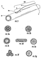
- Fig. 3 shows a perspective view of a generic distribution fiber optic cable 30 (hereinafter distribution cable 30) according to the present invention.
- Distribution cable 30 depicts a distribution optical fiber 32 protruding from a first access location 38a in a protective covering 38 such as a cable jacket.
- first access location 38a has an access length AL, which is the length of the opening or breach in protective covering 38.
- distribution optical fiber 32 has a distribution optical fiber length DOFL that is about 5/4 times the access length AL or longer and more preferably about 3/2 times the access length AL or longer. In other words, distribution optical fiber 32 was cut or severed at a cutting location CL within distribution cable 30.
- distribution optical fiber 32 has a distribution optical fiber length DOFL of about 6 centimeters or longer and more preferably about 7.5 centimeters or longer.
- the distribution optical fiber length DOFL is greater than the access length AL of the first access location 38a since the distribution optical fiber is cut from within the fiber optic cable.
- cable 30 may have any suitable number of distribution optical fibers 32 protruding from first access location 38a.
- fiber optic distribution cables can have any suitable number of access locations disposed along the cable as desired.
- Fiber optic distribution cables of the present invention may also use one or more different methods and/or components for constructing the fiber optic distribution cable based on the type of fiber optic cable selected and type of connectivity desired.
- Distribution cable 30 is generic since it represents fiber optic cables that allow cutting of the distribution optical fiber within the protective covering according to the present invention.
- Figs. 3a-3g depict a sampling of fiber optic cable constructions that are useful according to the present invention. Respectively Figs. 3a-3g depict: a stranded loose tube cable ( Fig. 3a ); a slotted core cable ( Fig. 3b ); a monotube cable ( Fig. 3c ); a flat ribbon cable ( Fig. 3d ); an indoor cable ( Fig. 3e ); a cable having a plurality of tubes lashed together ( Fig. 3f ); and a cable having bundles ( Fig. 3g ).
- distribution cable 30 can have any suitable construction.
- the present invention works with optical fibers of the different cables types such as a plurality of optical fiber ribbons, loose optical fibers, buffered optical fibers, bundles of optical fibers or the like.
- Fig. 4 depicts a flowchart 40 of a method for manufacturing a distribution cable using the concepts of the present invention.
- a step 41 of providing a distribution cable such as distribution cable 30 having a plurality of optical fibers (not visible) and a protective covering such as a cable jacket is required.
- a step 43.of making an opening (i.e., opening or breaching the protective covering) in the distribution cable at a first access location is performed for accessing one or more of the plurality of optical fibers within the distribution cable. More specifically, the protective covering is opened at the first access location with an access length AL that is sufficient for practicing the method disclosed herein.
- AL access length
- method 40 requires a step 45 of selecting at least one of the plurality of optical fibers of the distribution cable as a distribution optical fiber.
- a cutting location within the distribution cable means a location along the distribution cable where the protective covering is not breached.
- the step of cutting is performed by positioning and inserting a suitable cutting tool within the distribution cable, thereby allowing the tool to cut one or more distribution optical fibers at the cutting location within the distribution cable.
- a step 49 of routing the distribution optical fiber through the opening at the first access location so that a portion of the distribution optical fiber is disposed outside the protective covering is performed.
- the distribution cable can optionally include other steps and/or components such as providing a demarcation point, a transition tube, or components suitable for optical connectivity.
- the method of flowchart 40 is useful for either factory or field applications because it is simple, reliable, and craft-friendly.
- the method of flowchart 40 only requires one access location opening per distribution location and the distribution optical fiber length DOFL presented at the access location that is longer than the length of the cable breach or opening.
- Other methods may include one or more optional steps such as providing other components and/or other steps. More specifically, the method may further include one or more of the steps such as: providing a transition tube for routing the distribution optical fiber ( Fig. 6c ); providing a cap for closing the first access location ( Fig. 6c ); providing a demarcation point about the distribution optical fiber ( Fig. 6i ); providing a tether tube about the distribution optical fiber ( Fig.
- a kit of parts as disclosed herein is useful for practicing the methods and/or constructing the distribution cables of the present invention.
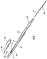
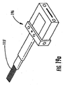
- Fig. 5 depicts an explanatory tool 50 for severing one or more distribution optical fibers within the distribution cable according to the invention.
- Tool 50 has an elongate body 52 having a first end 54 with an opening 56 and a cutting element 58.
- Cutting element 58 is flexible for fitting into opening 56 and is able to move through opening 56 when pulled, thereby severing or cutting one or more distribution optical fibers at the cutting location within the distribution cable. More specifically, pulling cutting element 58 causes the optical fibers captured by cutting element 58 to bend beyond their ultimate bending radii so that they are severed or cut. As best shown by Fig.
- cutting element 58 is looped about one or more distribution optical fibers and both ends 58a,58b of cutting element 58 are routed through opening 56 and positioned toward a second end 55 of tool 50 that is bent upward, thereby forming a handle for the operator. Thereafter, tool 50 can be slid into the distribution cable to the desired cutting location (i.e., the loop in the cutting element is adjacent to the cutting location) and then both ends 58a,58b of cutting element 58 are pulled until one or more distribution optical fibers within the distribution cable are severed. Consequently, the distribution optical fiber length DOFL has a length that is greater than the breach in the protective covering because the distribution optical fiber is cut within the distribution cable.
- Cutting element 58 requires certain characteristics for cutting or severing one or more distribution optical fibers.
- cutting element 58 must have the necessary strength for severing the distribution optical fiber without breaking when pulled and the flexibility for looping into the at least one opening of the elongate body while moving through the at least one opening when pulled.
- Cutting element 58 can use any suitable structure, size, shape, and/or material for meeting these requirements. Examples include structures such as one or more filaments, threads, rovings, or yarns and examples of shapes include round, rectangular, and the like.
- cutting element 58 is a aramid material such as Kevlar having a denier of about 2450.
- cutting element 58 may be formed from other suitable materials such as polymer material such as polyester or nylon, fishing line, a metallic material such as a steel wire, a cotton material, or the like. For instance, one embodiment may use fifty pound test fishing line such as sold under the tradename SpiderWire®.
- elongate body 52 may be formed from any suitable material such as metal or plastic that allow suitable dimensions for fitting within the selected distribution cable and yet remain somewhat flexible while having the necessary strength.
- elongate body 52 is formed from steel tape having a tool height TH of about 2 millimeters or less and a tool width TW of about 8 millimeters or less, thereby making it flexible in one direction.
- opening 56 has a generally rectangular shape with a length of about 5 millimeters and a width of about 2 millimeters, but opening 56 can have other suitable sizes and/or shapes.
- the size and shape of the elongate body can be tailored for the size and shape of the space of the distribution cable that the tool must fit within such as rectangular or round.
- a tool with an arcuate-shape or rod-shape may be better suited for sliding into a round buffer tube.
- other variations of tool 50 are contemplated by the present invention.
- Figs. 5b-5f depict variations on the explanatory tool according to the invention.
- Fig. 5b depicts a portion of a tool 50b that has a plurality of openings 56b near the first end. As depicted, tool 50b has three openings 56b so the location of cutting element 58 may be varied across the width of tool 50b.
- Fig. 5c depicts a portion of tool 50c having an opening 56c that is non-round and larger for easily passing the ends of the cutting element therethrough and guiding the cutting element when pulled. Likewise, the opening of the tool need not close on itself. For instance, Figs.
- FIG. 5d and 5e respectively depict portions of tools 50d and 50e where the openings 56d,56e are in communication with the outer edge of the tool, thereby making the insertion of cutting element 58 into the tools easier.
- Fig. 5f depicts tool 50f having a handle 57f having a movable portion 59f for pulling cutting element 58 in order to severe one or more distribution optical fibers.
- both ends 58a,58b of cutting element 58 are wrapped about a protrusion (not numbered) of moveable portion 59f of handle 57f so when it is actuated movable portion 59f pulls in the direction shown by the arrow, thereby pulling on both ends 58a, 58b of cutting element 58 to cut the distribution optical fiber.
- other tool variations are possible for pulling, wrapping, routing, mounting, or otherwise altering the tools disclosed for severing the distribution optical fiber.
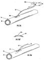
- Figs. 6a and 6b depict the use of tool 50 with distribution cable 30 of Fig. 3 . More specifically, Fig. 6a shows distribution cable 30 after the opening is made at the first access location and one or more optical fibers are selected as the distribution optical fibers. As further shown, cutting element 58 of tool 50 looped is about the plurality of distribution optical fibers 32 that were selected. Stated another way, tool 50 and its cutting element 58 are positioned to cut a plurality the optical fibers that are captured by the loop of the cutting element 58. Additionally, both ends 58a,58b of cutting element 58 are moved toward the second end 55 of tool 50 and cutting element 58 is snugged-up about distribution optical fibers 32.
- Fig. 6b illustrates tool 50 inserted within distribution cable 30 for severing a plurality of distribution optical fibers at cutting location CL.
- ends S8a,58b of cutting element 58 are pulled with a force sufficient to severe the distribution optical fibers 32 disposed between the loop of cutting element 58 and elongate body 52.
- the distribution optical fibers 32 that are severed within the distribution cable 30 are routed through the opening at the first access location 38a so that a portion of the distribution optical fiber is routed outside protective covering 38 as shown in Fig. 3 .
- distribution cables of the present invention may further include other manufacturing steps and/or other components for making other assemblies of the present invention such as splicing to the distribution optical fiber and/or attaching a ferrule to the distribution optical fiber.
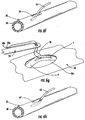
- kit of parts 60 for closing first access location 38a and routing the distribution optical fibers 32 outside protective covering 38.
- kit of parts 60 includes a transition tube 62 for routing and protecting distribution optical fibers 32 outside of protective covering 38 and a cap 64 for closing first access location 38a and shielding the other optical fibers within the distribution cable.
- the transition tube allows limited movement of the distribution optical fiber into and out of the distribution cable (i.e., allows pistoning) when it is bent.
- the transition tube allows the distribution optical fiber to have a pass-through construction permitting limited movement of the same using the transition tube as a pass-through conduit.
- a demacaration point is disposed about the distribution optical fiber at or near the access location, thereby generally inhibiting the pistoning of the same into and out of the distribution cable.
- the use of the pass-through construction or demarcation point construction may depend on the distribution cable construction and/or cable characteristics such as the degree of optical fiber coupling within the cable. In other words, some cable designs are better suited for free pass-through, while other cable configurations are better suited for the demarcation point.
- the transition tube may used with the demarcation point if distribution optical fiber is generally fixed by a material, thereby creating a demarcation point.
- cap 64 includes an opening 64a that is sized for receiving transition tube 62 therethrough such as round, rectangular, etc.
- transition tube 62 is slid over the distribution optical fibers 32 and may be pushed into a portion of distribution cable 30 as shown in Fig. 6e .
- transition tube 62 protects and routes distribution optical fibers as they transition from a position within the distribution cable to a position outside the distribution cable while allowing some movement.
- the exposed end of transition tube 62 is routed through opening 64a of cap 64 so transition tube 62 extends therefrom as represented by the dotted line in Fig. 6c .
- Transition tube 62 is formed from a suitable material that is flexible, but may also be formed from a relatively rigid material.
- transition tube 62 is a PTFE tube (i.e., a Teflon® tube) that is able to withstand the application of high temperatures.
- the PTFE transition tube is chemically etched.
- cap 64 is formed from a suitable material such as PTFE or other flexible material, but cap 64 may also be formed from a relatively rigid material.
- caps for closing the access location can have other configurations.
- Fig. 6h shows a cap 64' using a notch (not numbered) as the opening for routing the transition tube and/or optical fiber outward of the protective covering.
- the distribution optical fiber and/or transition tube pass through notch of cap 64' and a portion of the access location.
- kits of parts can include other components such as tools for cutting distribution optical fibers, tether tubes, indexing tubes, shrink tubing, sealing components, plugs and/or preconnectorized pigtails that may include ferrules, receptacles, connector bodies or the like.
- other distribution cable assemblies of the present invention may include other components or steps as discussed herein.
- cap 64 is larger than the opening of the access location AL (i.e., longer) and is disposed so that a portion of the same extends under protective covering 38. Additionally, cap 64 may be relatively thin and flexible so that it is easily tucked under protective covering 38 by the craft. By way of example, cap 64 is sized so that about 5 millimeters of cap 64 is disposed under protective covering 38 at the ends and has a thickness of about 0.3 millimeters. After cap 64 is in position, a step of securing the same using a material 66 may be performed as depicted in Fig. 6f .
- material 66 is a hot melt adhesive available from Loctite under the tradename Hysol 83245-232, but any suitable material or method may be used for securing the cap such as a glue, adhesive, silicone, sonic welding or the like as long as the material used is compatible with the optical fiber, ribbons, protective covering, and/or other components that it may contact. Additionally, cap 64 and/or material 66 may also function to inhibit any optional sealing material such as an overmolded sealing material from entering the distribution cable. Furthermore, it is possible to apply material 66 below cap 64.
- cap 64 can have other suitable configurations and can vary based on the distribution cable.
- cap 64 can be shaped or tailored to match the profile of the portion of the protective covering 38 that is removed from the distribution cable.
- the cap has a length and width to match the length and width of the opening of the first access location along with an inner and outer profile to match the protective covering profile of the section that was removed. Consequently, the cap closes the first access location with a generally flush surface.
- a generally round distribution cable jacket would use a cap having a similar inner and outer radius as the cable jacket with a suitable arc length, longitudinal length, and width to match the access location opening.
- cap 64 shows a cross-sectional view of cap 64 shaped for closing the access location of a generally round distribution cable, but other shapes, profiles, and/or lengths of the cap are possible to tailor the cap to fit other cables and/or openings. Additionally, cap 64 may be attached at the first access location 38a using a suitable material or method such as an adhesive, glue, sonic welding, or the like.
- the method of flowchart 40 requires selecting at least one optical fiber of the plurality of optical fibers of the distribution cable as a distribution optical fiber.
- Distribution cables can have any suitable arrangement and/or type of optical fibers therein and the concepts of the invention are useful with the different arrangements and/or types of optical fibers.
- the present invention is suitable with cables having bare optical fibers (e.g., the stranded loose tube cable of Fig. 3a ) and cables having one or more ribbons (e.g., the slotted core cable of Fig. 3b , the monotube cable of Fig. 3c , or the flat ribbon cable of Fig. 3d ).
- Still other distribution cables may have buffered optical fibers ( Fig.
- Distribution cables having buffered optical fibers may require more force on the cutting element to severe the buffer layer and the optical fiber but are within the scope of the present invention.
- a dividing tool such as a thin piece of metal or plastic may be used at the access location for separating the selected optical fibers from the remaining portion of the distribution cable.
- a ribbon R has a split S formed by the craft between the fourth and fifth optical fibers of ribbon R for a short distance near the access location.
- the desired optical fibers for distribution are segregated for splitting ribbon R along its longitudinal length before cutting the same. More specifically, Fig. 6g shows that cutting element 58 of tool 50 is then looped about the four segregated optical fibers of split ribbon R and tool 50 is positioned as before.
- the split S in the ribbon is propagated along its longitudinal length by the tool within the distribution cable.
- cutting element 58 splits the ribbon along its longitudinal length by shearing the matrix material of the ribbon between the desired optical fibers as tool 50 is slid into position to the cutting location.
- the selected distribution optical fiber(s) is severed as before using the tool.
- the distribution optical fiber can be generally fixed for inhibiting movment.
- Fig. 6i depicts a distribution cable 30' having a demarcation point 80 for generally inhibiting the movement of the distribution optical fiber 32' at or near the access location.
- demarcation point 80 fixes the distribution optical fiber near the access location for inhibiting movement of the same to reduce undue stresses on the distribution optical fiber such as during bending, thereby preserving optical performance.
- One method for providing demarcation point 80 is by applying or injecting a suitable material about the distribution optical fiber 32' at the access location. For instance, the demarcation material may be applied and/or injected into the distribution cable about the distribution optical fiber, thereby inhibiting the movement of the distribution optical fiber.
- demarcation point 80 may be used with or without a cap 64' and may be disposed inward or outward of the cap if used. If the cap is omitted, demarcation point 80 may also function to inhibit any optional sealing material such as an overmolded sealing material from entering the distribution cable.
- Fig. 6i depicts a generic distribution cable 30' having a first and second opening 38a',38b' in protective covering 38'.
- the demarcation point 80 is used with a conventional access method where the cable is opened in two locations 38a' and 38b' for obtaining the desired length of distribution optical fiber.
- one or more of openings 38a', 38b' can be closed with suitable a cap 64'as depicted.
- the method of providing excess fiber length for the distribution optical fiber by indexing as discussed below can be performed without cutting the distribution optical fiber from within the distribution cable.
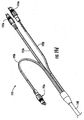
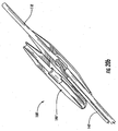
- Figs. 7 and 8 respectively are a perspective and an exploded view and of a specific explanatory fiber optic distribution cable assembly 100 (hereinafter cable assembly 100) according to the present invention.
- distribution cable assembly 100 includes a distribution cable 110, a distribution optical fiber pigtail 115', a cap 120 for access location AL, a transition tube 130, a tether tube 140, an indexing tube 150, an indexing tube plug 160, a splice protector 170, a heat shrink tube 180, and a sealing portion 190.
- Figs. 9-11 are cross-sectional views of assembly 100 respectively taken along line 9-9, line 10-10, and line 11-11. Additionally, Figs.
- Cable assembly 100 includes indexing tube 150 so that a predetermined amount of excess ribbon length (ERL) or excess fiber length (EFL) can be loaded into the distribution optical fiber as will be discussed. Loading ERL or EFL into the distribution optical fibers inhibits stresses on the same such as during bending of the cable assembly. Additionally, cable assembly 100 is one example of many different distribution cables according to the present invention that may include fewer or more components, components having different configurations, different arrangement of components, or the like.
- Fig. 9 depicts that both distribution fiber optic cable 110 and tether tube 140 have a generally non-round cross-section such as a generally flat shape, thereby allowing a relatively small overall cross-sectional dimension for assembly 100.
- flat portions of distribution cable 110 and tether tube 140 are generally aligned to allow a small footprint compared with using two round cables.
- distribution cable assembly 100 and other similar assemblies can have a cross-sectional maximum dimension MD as shown in Fig. 11 , which is along a diagonal.
- Cross-sectional maximum dimension MD can vary based on the size of the components used, but in embodiments advantageous for duct specific applications the cross-sectional maximum dimension is about 30 millimeters or less, more preferably about 28 millimeters or less, and most preferably about 25 millimeters or less, thereby allowing the pulling of the cable assembly into the duct. Of course, other embodiments can have other larger or smaller cross-sectional maximum dimensions for the given application.
- Distribution cable 110 is advantageous for several reasons, but the use of other distribution cables is possible.
- distribution cable 110 and other similar distribution cables are advantageous since they can have a relatively high optical waveguide count with a relatively small cross-sectional footprint.
- distribution cable 110 has four ribbons each having twenty-four optical fibers for a total fiber count of ninety-six fibers. With twenty-four fiber count ribbons, distribution cable 110 has a major cable dimension W of about 15 millimeters or less and a minor cable dimension H of about 8 millimeters or less.
- Second, distribution cable 110 is easily accessed from either of the generally planar surfaces (e.g., top or bottom) of the cable so that the craft is able to access to any optical fiber desired for distribution.
- distribution cable 110 allows quick and reliable access while inhibiting damage to the optical fibers or strength members during the access procedure. In other words, the craftsman can simply cut into the protective covering, thereby gaining access to the cable cavity having the optical fibers therein. Also, in this embodiment, distribution cable 110 has a dry construction (i.e., the cable excludes a grease or gel for water-blocking), thus the raft does not have to clean or remove grease or gels from the optical fibers, ribbons, tools, etc.
- distribution cables according to the present invention may have any suitable dimensions, constructions, and/or fiber counts for the given application.
- other distribution cables can include other components and/or structures for water-blocking such as grease, gel, extruded foams, silicones, or other suitable water-blocking components.
- suitable water blocking structures may also be intermittent disposed along the distribution cable.
- other distribution cables can have other suitable cable components such as armor, ripcords, or tubes.
- another embodiment of the distribution cable may have a toneable portion for locating the cable in buried applications.
- distribution cable 110 includes a plurality of optical fibers 112 and a protective covering 118.
- distribution cable 110 is a tubeless design having a cavity 111 for housing a plurality of optical fibers 112, which are configured as a plurality of ribbons 113 (represented by the horizontal lines) arranged in a non-stranded stack.
- Distribution cable 110 also includes strength members 114 and water-swellable components 116. As depicted, strength members 114 are disposed on opposite sides of cavity 111 and impart a preferential bend characteristic to distribution cable 110. Strength members 114 provide tensile and/or anti-buckling strength to the distribution cable and may be formed from any suitable materials such as dielectrics, conductors, composites or the like.
- strength member 14 are a round glass-reinforced plastic (grp) having a diameter of about 2.3 millimeters, which is smaller than the height of cavity 111.
- strength members 14 can have shapes other than round such as oval strength members.
- Water-swellable components 116 allows for a dry construction of distribution cable 110.
- Water-swellable components 116 can have any suitable form such as water-blocking yarn, thread, tape or the like.
- distribution cable 110 uses two water-swellable components 116 configured as elongate tapes that are paid-off reels.
- the major (e.g. planar) surfaces (not numbered) of water swellable components 116 are generally aligned with the major (e.g. horizontal) surfaces (not numbered) of cavity 111, thereby allowing a compact and efficient configuration while generally inhibiting corner optical fiber contact as occurs with a ribbon stack disposed in a round tube.
- the ribbons are generally aligned with a major surface (i.e.
- the rectangular (or square) ribbon stack is fitted to a corresponding generally rectangular (or square) cavity and avoids the issues associated with placing a rectangular (or square) ribbon stack within a round buffer tube (i.e. stresses on the corner fibers of the ribbon stack in a round buffer tube that can cause the cable to fail optical performance requirements such as bending).
- water-swellable components 116 are disposed on the top and bottom of the ribbon stack (not numbered) and include a compressible layer 116a and a water-swellable layer 116b.
- water-swellable components 116 sandwich the plurality of ribbons 113 of the non-stranded stack, thereby forming a cable core. Consequently, the ribbon(s) 113, major surfaces of water-swellable components 116, and major (horizontal) surfaces of cavity 111 are generally aligned (i.e., generally parallel) to create a compact structure. Additionally, water-swellable components 116 contact at least a portion of respective the top or bottom ribbons.
- one or more elongate tapes may be wrapped about the optical fibers or disposed on one or more sides thereof.
- compressible layer 116a is a foam layer such as open cell polyurethane material and water-swellable layer 116b is a water-swellable tape.
- other suitable materials are possible for the compressible layer and/or water-swellable layer or portion. As shown, compressible layer 116a and water-swellable layer 116b are attached together, but they may be applied as individual components.
- water-swellable component 116 is multi-functional since it provides a degree of coupling for the ribbons 113, inhibits the migration of water along cavity 111, cushions the ribbons/optical fibers, and allows movement and separation of the ribbons (or optical fibers) to accommodate bending of distribution cable 110.
- distribution cables may use other cable components disposed within the cavity 111 for coupling the optical fibers, cushioning the optical fibers, and/or water-blocking.
- distribution cables may use a foam tapes or extruded foam that does not include a water-blocking characteristic.
- cavity 111 has a generally rectangular shape with a fixed orientation to accommodate the non-stranded ribbon stack, but other shapes and arrangements of the cavity are possible such as generally square, round, or oval.
- cavity may be rotated or stranded in any suitable manner along its longitudinal length.
- the cavity can also have a partial oscillation through a given angle, for instance, the cavity can rotate between a clockwise angle that is less than a full rotation and then rotate counter-clockwise for less than a full rotation.
- cavity 111 may be offset towards one of the planar surfaces of distribution cable 110, thereby allowing easy opening and access from one side.
- Ribbons 113 used in distribution cable 110 can have any suitable design or ribbon count.
- ribbons 113 can have a splittable construction using one or more subunits or stress concentration as known in the art, thereby allowing separation of the ribbon into smaller groups of optical fibers.
- a ribbon may use subunits each having four optical fibers; however, ribbons without subunits are possible and subunits may have different fiber counts.
- Subunits allow predetermined splitting of the optical fiber ribbons into predictable smaller fiber count units before splitting along its length with tool 50.
- each of the depicted ribbons 113 includes six four-fiber subunits for a total of twenty-four optical fibers.
- optical fibers per ribbon are possible such as two twelve fiber units, three eight fiber units, or six four fiber units depending on the requirements of the network architecture.
- suitable optical fiber arrangements include ribbons with or without subunits, ruggedized ribbons having a tight-buffer layer, tight-buffered or colored optical fibers, loose optical fibers in a tube, optical fibers in a module, or optical fibers disposed in a bundle.
- ribbons 113 of this explanatory embodiment of distribution cable 110 have an excess ribbon length (ERL) of about 0.5% or more such as in range of about 0.6% to about 0.8% to accommodate bending and/or coiling of distribution cable 110, but the amount of ERL used may vary based on the specific cable design.
- the ERL of ribbons 113 is related to the ERL of the ribbons within the cable and is different than the loading of ERL in the distribution optical fiber using the indexing tube as briefly discussed above.
- the minimum bend radius of the distribution cable 110 is about 125 millimeters which allows the cable to be coiled in a relatively small diameter for slack storage.
- distribution cables with other suitable fiber/ribbon counts may have other ERL values and/or cable dimensions.
- cables similar to distribution cable 110 could have four ribbons with different fiber counts such as: (1) twelve fiber ribbons with a major cable dimension W of about 12 millimeters or less for a total of forty-eight optical fibers; (2) thirty-six fiber ribbons with a major cable dimension W of about 18 millimeters or less for a total of one-hundred and forty-four optical fibers; or (3) forty-eight fiber ribbons with a major cable dimension W of about 21 millimeters or less for a total of two-hundred and sixteen optical fibers.
- cavity 111 has a cavity height CH and a cavity width CW suitable for the desired arrangement of optical fibers, ribbon, or the like.
- each ribbon 113 has a height of about 0.3 millimeters for a total ribbon height of about 1.2 millimeters (4 times 0.3 millimeters) and the cavity height CH is about 5.5 millimeters for cavity 111.
- Cavity width CW is generally determined by the width of the ribbons (or number of optical fibers) intended for the cable and would be about 7.5 millimeters for the twenty-four fiber ribbons.
- water-swellable components 116 each have an uncompressed height of about 1.8 millimeters, but other suitable uncompressed heights are possible.
- the compression of water-swellable components 116 in the cable is the localized maximum compression of the same and generally occurs where the ribbon or ribbon stack has the maximum displacement from the neutral axis if the cable includes a positive EARL (i.e., the ribbons undulate within the cavity).
- the explanatory embodiment has a total height for the uncompressed water-swellable components 116 and ribbon 113 of about 4.8 millimeters, which is less than the cavity height CH of 5.5 millimeters. Consequently, a normalized ribbon pullout force is generally caused by the undulating ribbon stack causing localized maximum compression of the water-swellable components 116 due to the ERL and/or friction.
- proper coupling of the ribbon stack may be achieved when the combined uncompressed height of the dry inserts is about 40% or more of the cavity height CH such as by using two 1 millimeter water-swellable components 116 within a cavity having a cavity height CH of about 5 millimeters.
- the combined uncompressed height (2 times 1.8 millimeters equals 3.6 millimeters) of water-swellable components 116 is about 65% of the cavity height CH (5.5 millimeters), which is more than 50% of the cavity height CH.
- the cavity, ribbons, and/or water-swellable components 116 can have other suitable dimensions while still providing suitable performance. For instance, thinner ribbons and/or water-swellable components may be used.
- cavity 111 is depicted as rectangular it may be difficult to make a rectangular cavity as shown, i.e., the extrusion process may create the cavity with a somewhat irregular rectangular shape.
- the cavity can have other suitable shapes besides generally rectangular such as oval, round or the like, which may generally change the relationship (alignment) among the dry insert, ribbon, and/or cavity.
- positioning water-swellable components 116 on opposite ends of the ribbon stack aids in influencing and maintaining a generally uniform ERL distribution along distribution cable 110 during different conditions, thereby helping to preserve optical performance.
- ribbon to cable coupling is beneficial for influencing a relatively even ERL distribution along the cable such as during bending, which generally allows for small cable bend radii.
- Other factors such as the size of cavity and/or compression of the dry insert(s) may also influence ERL/EFL distribution along the cable.
- Another optical performance aspect of distribution cables having a generally flat profile with a non-stranded ribbon stack is the total amount of ERL required for suitable cable performance.
- the amount of ERL for adequate cable performance generally depends on the cable design such as the number of ribbons.
- the minimum ERL for cables having a single ribbon is determined by the desired allowable level of fiber strain at the rated cable load; whereas, the minimum ERL for a multiple ribbon cable is generally influenced by bending performance. More specifically, when selecting the minimum ERL limit for a cable design the strength member geometry and material (i.e. cross-sectional area and Young's modulus) should be considered for calculating the desired level of fiber strain at the rated tensile load of the cable design.
- ERL excess fiber length
- FIGs. 12-16 depict perspective views showing portions of distribution cable 110 in various stages of construction (i.e., subassemblies) for explaining the method of making cable assembly 100.
- Fig. 12 depicts distribution cable 110 after access location AL is made in protective covering 118 and distribution optical fibers 115 are cut within distribution cable 110 and routed through the opening at access location AL with cap 120 and transition tube 130 installed, thereby forming a subassembly 102 of cable assembly 100.
- a variety of distribution cables may be constructed such as cable assembly 100 shown in Figs. 7 and 8 or a cable assembly 200 as shown in Figs. 17 and 18 .
- subassembly 102 or other subassembly constructions are suitable for deployment in the field.
- the distribution optical fibers of subassembly 102 are presented outside of the distribution cable for use by the craft in the field. If used in this manner, a tape or other covering may be disposed about the distribution optical fibers and/or access location for protecting the same until access is needed in the field.
- Subassembly 102 is formed as described below.
- protective covering 118 of distribution cable 110 about access location AL is roughened by scalloping and/or flame brushing as shown. Roughening protective covering 118 improves the adhesion of sealing portion 190 with the same and is easier and safer to accomplish before opening protective covering 118.
- an opening 118a of access location AL is made in protective covering 118. Opening 118a may be any suitable length and in this case is about 25 millimeters long. Any suitable cable entry tool may be used for opening protective covering 118 such as a utility knife or the like.
- a portion of the top water-swellable component 116 of distribution cable 110 is exposed at access location AL.
- the exposed portion of water-swellable component 116 is removed such as by cutting with a scissors, thereby allowing for easier access to the optical fibers within distribution cable 110. Thereafter, the desired optical fibers for distribution are selected for cutting within the distribution cable and special tools such as the dividing tool may be used.
- special tools such as the dividing tool may be used.
- less than all of the optical fibers of the top ribbon are selected for distribution so the top ribbon includes split S between optical fibers like depicted in Fig. 6f .
- four optical fibers of the top ribbon are selected to become distribution optical fibers at access location AL.
- optical fibers from other ribbons in the stack may be selected for distribution.
- split S in the top ribbon is made by the craft using a suitable tool and/or their fingers. Thereafter, cutting element 58 of tool 50 is positioned about split S like depicted in Fig. 6f . Then, the slack of cutting element 58 is taken up and tool 50 is slid into cavity 111 of distribution cable 110, thereby splitting the ribbon between optical fibers along its longitudinal length as tool 50 moves into position. After tool 50 is positioned at the cutting location CL within distribution cable 110 cutting element 58 is pulled with sufficient force to cut distribution optical fibers 115 within distribution cable 110.
- tool 50 is inserted so as to cut distribution optical fibers 115 about 175 millimeters downstream from access location AL. Consequently, the distribution optical fiber length DOFL is about seven (7) times longer than the access length AL.
- distribution optical fibers 115 are pulled out of cavity 111 and presented outward of protective covering 118.
- cap 120 which is similar to cap 64
- transition tube 130 which is similar to transition tube 62
- transition tube 130 has a length of about 65 millimeters and a generally rectangular shape for sliding over optical fibers split from optical fiber ribbon 113 and cap 120 is generally flat and has a length that is slightly longer than access location AL so that a portion may fit within cavity 111 of distribution cable 110. Transition tube 130 is slid over distribution optical fibers 115 so that about 35 millimeters is disposed within cavity 111 of distribution cable 110. Then, the exposed end of and transition tube 130 is routed through an opening 120a of cap 120 and cap 120 is positioned so that a portion of the same is tucked into cavity 111 of distribution cable 110. As before, cap 120 closes access location AL and transition tube 130 protects distribution optical fibers 115 as they are routed out of distribution cable 110. Thereafter, a material (not shown) such as a hot melt adhesive is applied above cap 120 and about transition tube 130 for securing cap 120 and transition tube 130 at the opening of the access location like as shown in Fig. 6f .
- a material such as a hot melt adhesive is applied above
- Fig. 13 depicts a perspective view of another subassembly 104 of cable assembly 100 for explaining the method of making. More specifically, Fig. 13 shows subassembly 102 of Fig. 12 after splicing distribution optical fiber 115 with distribution optical fiber pigtail 115' and protecting the splice location with splice protector 170.
- the distribution optical fiber pigtail 115' is a four fiber ribbon that is mass fusion spliced with the distribution optical fibers 115 that were split out of the top ribbon.
- distribution optical fiber pigtail 115' is in optical communication with distribution optical fiber 115 and becomes part of the same.
- this step increases the length of the distribution optical fiber based upon the desired connectivity configuration such as the length of the tether tube or other configurations.
- Splice protector 170 is used for protecting and immobilizing the splice (not visible) and may be pushed onto distribution optical fiber pigtail 115' before splicing and then positioned over the splice after it is made. Likewise other components may be slid over distribution optical fiber pigtail 115' depending on the configuration of the embodiment.
- a variety of distribution cables may be constructed from subassembly 104 or other similar subassemblies.
- Cable assembly 100 includes tether tube 140 with a distribution optical fiber stub (the second end of distribution optical fiber pigtail 115') for optical connectivity, but other configurations are possible.
- the second end of the distribution optical fiber 115' can have one or more ferrules attached thereto and the ferrule may be a portion of a receptacle, plug, or the like for plug and play connectivity.
- Fig. 19 depicts a second end of tether tube 140' having the distribution optical fiber attached to a ferrule that is a portion of plug 195 as known in the art.
- the second end of tether tube 140' can have any suitable configuration for connectivity such as splice-ready optical fibers, a connector or a receptacle having a ferrule, a multi-port or the like, thereby allowing the craft flexibility for downstream connectivity.
- Fig. 19a depicts distribution optical fibers 115' attached to a ferrule 196.
- Ferrule 196 is a multifiber ferrule, but single fiber ferrules may be attached to one or more distribution optical fibers.
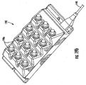
- Fig. 19b depicts a multi-port 198 having a plurality of receptacles 198a attached to the end of tether tube 140.
- Fig. 19a depicts distribution optical fibers 115' attached to a ferrule 196.
- Ferrule 196 is a multifiber ferrule, but single fiber ferrules may be attached to one or more distribution optical fibers.
- Fig. 19b depicts a multi-port 198 having a plurality of
- FIG. 19c depicts another multi-port 199 having a plurality of receptacles 199a attached to the end of tether tube 140.
- Figs. 19d and 19e depicts a branching of tether tube using furcation legs for providing plug and play connectivity. More specifically, Fig. 19d shows assembly 193 having a plurality of plugs 193a disposed on the ends of a plurality of furcation legs 193b and Fig. 19e shows assembly 194 having a plurality of receptacles 194a disposed on the ends of a plurality of furcation legs 194b.
- optical connectivity such as single receptacle or the like.
- cable assembly 100 has the splice disposed within the cavity of indexing tube 150 as will be explained below for protecting the splice and loading an ERL or EFL into the distribution optical fiber.
- splicing indexing tube 150 is slid over a portion of distribution optical fiber 115 and a portion of transition tube 130. Consequently, splice protector 170 is disposed within a cavity 150a of indexing tube 150 and fiber pigtail 115' extends from a second end of indexing tube 150. Furthermore, splice 170 can have an optional cushioning element (not shown) such as a foam tape disposed thereabout. For instance, the foam can be positioned about splice 170 such as folded over the same before indexing tube 150 is slid thereover. As further shown, indexing tube plug 160 is then pushed into the upstream end of indexing tube 150.
- an optional cushioning element such as a foam tape
- Indexing tube plug 160 is used for inhibiting sealing portion 190 from being injected into indexing tube 150 in a further manufacturing process.
- Indexing tube plug 160 may be formed from any suitable material such as a foam, soft polymer, or the like and is sized for fitting into the cavity of the indexing tube 150 along with transition tube 130 as a light friction fit. Then, if desired, indexing tube 150 may be taped or secured to distribution cable 110 for holding the same in place at a suitable position. In this embodiment, indexing tube 150 is a portion of distribution cable 110 having an empty cavity as best shown by Fig. 11 .
- indexing tube 150 is a portion of distribution cable 110 with the ribbons 113 and water-swellable components 116 removed from cavity 111 (i.e., just the protective covering 118 having strength members 114 embedded therein).
- suitable indexing tubes having other sizes and/or shapes such as round, square, etc is possible.
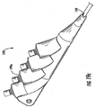
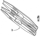
- Fig. 14 depicts a perspective view of a subassembly 106 of cable assembly 100 disposed within a mold 192 as shown by the phantom lines before injecting a curable material for forming the sealing portion 190.
- Subassembly 106 further includes a step of applying a material 106a such as a hot melt adhesive for sealing and/or securing components of the assembly together such as fixing the position of transition tube 130. Applying material 106a inhibits the injected material from entering the opening of the access location, indexing tube 150, and/or from moving components during the overmolding process, thereby preserving optical performance.
- a material 106a such as a hot melt adhesive for sealing and/or securing components of the assembly together such as fixing the position of transition tube 130. Applying material 106a inhibits the injected material from entering the opening of the access location, indexing tube 150, and/or from moving components during the overmolding process, thereby preserving optical performance.
- sealing portion 190 may be beneficial to heat up a portion of subassembly 106 shortly before forming sealing portion 190 therearound to promote bonding of sealing portion 190 with subassembly 106. Thereafter, subassembly 106 is placed into mold 192 as shown in Fig. 14 and sealing portion 190 is formed by injecting the sealing material into the mold under pressure. Sealing portion 190 provides environment protection for the access location AL and may provide structural integrity.
- sealing portion 190 is a 2-part material formed of isocyanate resin and polyol hardener available from Loctite. In this embodiment, sealing portion 190 has a generally uniform minimum wall thickness of about 3-5 millimeters, but other dimensions are possible.
- sealing portion 190 can be formed by techniques or manufacturing methods other than by injecting a curable material into a mold.
- Fig. 20 depicts a sealing portion 190' that is a preformed shell that fits over subassembly 106 and then has heat (or other reactions) for partially or totally melting and/or forming the same, thereby sealing the access location.
- sealing portion 190' has a hinge line 192' for allowing the same to be folded about subassembly 106.
- sealing portion 190' can be two or more separate portions. Sealing portions such as sealing portions 190' can be used with any suitable distribution cable.
- Figs 20a-c depict the use of an alternative sealing portion 190" with a distribution cable 110' and tether tube 140' that have round cross-sections, thereby forming cable assembly 100'.
- a ruggedized tubing (not shown) may be placed about the access location and then injected with a suitable material for sealing the ends or the entire ruggedized tubing. If the application allows, sealing portion 190 may also be formed using a heat shrink tubing disposed about the access location.
- Fig. 15 depicts a perspective view of a subassembly 108 of cable assembly 100 before tether tube 140 is indexed with respect to indexing tube 150. More specifically, indexing tether tube 140 into and relative to indexing tube 150 enables the loading a predetermined amount of ERL into distribution optical fiber 115 and/or distribution optical fiber pigtail 115'. Consequently, the ERL or EFL of the distribution optical fiber inhibits forces from being applied to the same that may cause reliability and/or optical attenuation issues. As best depicted in Fig. 10 , cavity 150a of indexing tube 150 is sized so that tether tube 140 fits into the same. Fig.
- tether tube 140 includes a plurality of strength members 142 disposed on opposite sides of a cavity 141 and houses a portion of distribution optical fiber 115' therein.
- Tether tube 140 has a generally flat shape, but other sizes and/or shapes of tether tube may be used with the concepts of the present invention.
- Fig. 15 shows tether tube 140 disposed within a portion of indexing tube 150 and pulled taut for removing excess ribbon length as represented by mark M1. Thereafter, tether tube 140 is pushed (i.e., indexed) into indexing tube 150 a predetermined distance D represented by mark M2.
- distance D is about 5 millimeters, thus an ERL of about 5 millimeters is introduced into the distribution optical fiber that generally speaking accumulates within the indexing tube 150.
- other suitable distances D may be used for loading the desired ERL or EFL.
- tether tube 140 needs to be fixed in position for maintaining the ERL or EFL.
- heat shrink tubing 180 is applied over a portion of tether tube 140 and a portion of indexing tube 150 for maintaining the relative positions, but other methods are possible for maintaining relative positions such as overmolding or the like.
- Fig. 16 depicts cable assembly 100 having an optional cable tie 196 for securing distribution cable 110 and sealing portion 190 near the downstream end, thereby inhibiting a separation force between the two.
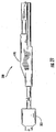
- Figs. 17 and 18 depicts cable assembly 200 which includes subassembly 102 having a distribution optical fiber pigtail 115' spliced thereto and protected by a splice protector 270.
- distribution optical fiber pigtail 115' includes a ferrule (not visible) attached thereto.
- the ferrule is a multifiber ferrule.
- the ferrule is a portion of a connector body 220, thereby providing plug and play optical connectivity at the access location, instead of at the end of the tether tube.
- cable assemblies 100 and 200 are examples of a multitude of distributioin cables made according the concepts of the disclosure. As discussed, other assemblies could use other cable cross-sections or have fewer, more, and/or different components.
- the sealing portion 190 of distribution cable 100 may include a segmented end 190a as shown by the phantom lines in Fig. 7 . Segmented end 190a allows some strain relief for the leading end of the distribution location.
- cable assemblies of the present invention can include other components such as for aiding the installation of the same into a duct.
- Fig. 21 depicts a distribution cable 300 having a pulling safety device 302 disposed ahead of the access location as depicted.
- pulling safety device 302 allows the craft to detect blockages and/or constrictions in a duct so that the craft does not damage the access location trying to pull the distribution cable past the blockage or constriction in the duct.
- safety pulling device is sized to be slightly larger than the sealing portion 190, thereby allowing the craft to sense an increased force and/or damage pulling safety device 302 before reaching the access location.
- the safety pulling device could have a size and/or shape that is similar or the same as the sealing portion. Consequently, the craft can pull the distribution cable out of the duct before damaging the same and repair or clear the duct before trying to reinstall the distribution cable.
- safety pulling device can be shaped to promote twisting or alignment of the distribution cable to fit past the blockage or constriction.
- fiber optic cables may include other suitable cable components such as ripcords or the like or other components for optical connectivity.
- the present invention cover the modifications and variations of this invention provided they come within the scope of the appended claims.
Landscapes
- Physics & Mathematics (AREA)
- General Physics & Mathematics (AREA)
- Optics & Photonics (AREA)
- Light Guides In General And Applications Therefor (AREA)
Claims (15)
- Lichtleitfaserverteilerkabel (110), das Folgendes umfasst:mehrere Lichtleitfasern (112);eine Schutzabdeckung (118);mindestens eine Verteilerlichtleitfaser (112), die als eine der mehreren Lichtleitfasern ausgewählt wird, wobei die mindestens eine Verteilerlichtleitfaser von einer Zugangsstelle (AL) der Schutzabdeckung (118) vorsteht;einen Versiegelungsabschnitt (190), der um die Zugangsstelle angebracht ist;einen Indizierungsschlauch (150), wobei der Indizierungsschlauch (150) einen Abschnitt, der durch den Versiegelungsabschnitt (190) befestigt ist, und einen weiteren Abschnitt des Indizierungsschlauchs (150), der sich über den Versiegelungsabschnitt (190) hinaus erstreckt, besitzt; undeinen Halteschlauch (140), der um einen Abschnitt der mindestens einen Verteilerlichtleitfaser (112) angeordnet ist, wobei der Halteschlauch (140) an einer vorbestimmten Position relativ zu dem Indizierungsschlauch (150) befestigt ist, wodurch in die Verteilerlichtleitfaser eine überschüssige Faserlänge geladen wird.
- Kabel nach Anspruch 1, das ferner einen Schrumpfschlauch (180) umfasst, der um einen Abschnitt des Indizierungsschlauchs (150) angebracht ist, um eine relative Position zwischen dem Indizierungsschlauch (150) und dem Halteschlauch (140) aufrecht zu halten.
- Kabel nach Anspruch 1, wobei die Zugangsstelle eine Länge AL hat und die Verteilerlichtleitfaser (112) eine Verteilerlichtleitfaserlänge DOFL von ungefähr 5/4 AL oder mehr vor dem Spleißen hat.
- Kabel nach Anspruch 1, wobei der Kabelquerschnitt und der Querschnitt des Halteschlauchs (140) beide nicht rund sind.
- Kabel nach Anspruch 1, wobei die maximale Abmessung des Querschnitts des Lichtleitfaserverteilungskabels (110) ungefähr 30 Millimeter oder weniger beträgt.
- Kabel nach Anspruch 1, das ferner einen Übergangsschlauch (130) für die Verteilerlichtleitfaser (112) umfasst.
- Kabel nach Anspruch 1, das ferner eine Kappe (120) zum Verschließen der Zugangsstelle und einen Übergangsschlauch (130), um einen Abschnitt der Verteilerlichtleitfaser zu schützen, umfasst.
- Kabel nach Anspruch 1, wobei die Verteilerlichtleitfaser (112) mindestens eine Lichtleitfaser aus einem Lichtleitfaserband ist.
- Kabel nach Anspruch 1, das ferner eine Pressklemme, die an der Verteilerlichtleitfaser (112) befestigt ist, umfasst.
- Kabel nach Anspruch 1, wobei das Verteilerlichtleitfaserkabel (110) eine Trockenkonstruktion hat.
- Verfahren für die Herstellung des Lichtleitfaserverteilerkabels nach Anspruch 1, das folgende Schritte umfasst:Bereitstellen mehrerer Lichtleitfasern und einer Schutzhülle;Ausbilden einer Öffnung in der Schutzhülle an einer ersten Zugangsstelle, um die mehreren Lichtleitfasern zu erreichen;Auswählen mindestens einer der mehreren Lichtleitfasern als eine Verteilerlichtleitfaser;Führen der Verteilerlichtleitfaser durch die Öffnung in der ersten Zugangsstelle, so dass sich die Verteilerlichtleitfaser außerhalb der Schutzhülle befindet; undIndizieren eines Halteschlauchs in einem Indizierungsschlauch, um die Verteilerlichtleitfaser mit einer überschüssigen Faserlänge zu versehen.
- Verfahren nach Anspruch 11, das ferner den Schritt umfasst, einen Schrumpfschlauch bereitzustellen, der über einem Abschnitt des Indizierungsschlauchs befestigt ist, um eine relative Position zwischen dem Indizierungsschlauch und einem Halteschlauch aufrecht zu halten.
- Verfahren nach Anspruch 11, das ferner den Schritt umfasst, die Verteilerlichtleitfaser an einer Schnittposition innerhalb des Lichtleitfaserverteilerkabels zu schneiden.
- Verfahren nach Anspruch 11, das ferner den Schritt umfasst, die erste Zugangsstelle zu versiegeln.
- Verfahren nach Anspruch 11, das ferner den Schritt umfasst, eine Muffe zu befestigen.
Priority Applications (2)
| Application Number | Priority Date | Filing Date | Title |
|---|---|---|---|
| PL16157145T PL3067726T3 (pl) | 2006-05-11 | 2007-05-11 | Kable światłowodowe rozdzielcze i ich konstrukcja |
| EP16157145.0A EP3067726B1 (de) | 2006-05-11 | 2007-05-11 | Faseroptische verteilungskabel und strukturen dafür |
Applications Claiming Priority (5)
| Application Number | Priority Date | Filing Date | Title |
|---|---|---|---|
| US43265406A | 2006-05-11 | 2006-05-11 | |
| US11/432,579 US8582938B2 (en) | 2006-05-11 | 2006-05-11 | Fiber optic distribution cables and structures therefore |
| US11/432,311 US7346243B2 (en) | 2006-05-11 | 2006-05-11 | Methods for manufacturing fiber optic distribution cables |
| US11/432,637 US7693374B2 (en) | 2006-05-11 | 2006-05-11 | Tools and methods for manufacturing fiber optic distribution cables |
| PCT/US2007/011471 WO2008008115A2 (en) | 2006-05-11 | 2007-05-11 | Fiber optic distribution cables and structures therefor |
Related Child Applications (2)
| Application Number | Title | Priority Date | Filing Date |
|---|---|---|---|
| EP16157145.0A Division EP3067726B1 (de) | 2006-05-11 | 2007-05-11 | Faseroptische verteilungskabel und strukturen dafür |
| EP16157145.0A Division-Into EP3067726B1 (de) | 2006-05-11 | 2007-05-11 | Faseroptische verteilungskabel und strukturen dafür |
Publications (2)
| Publication Number | Publication Date |
|---|---|
| EP2016453A2 EP2016453A2 (de) | 2009-01-21 |
| EP2016453B1 true EP2016453B1 (de) | 2016-04-20 |
Family
ID=38923726
Family Applications (2)
| Application Number | Title | Priority Date | Filing Date |
|---|---|---|---|
| EP16157145.0A Active EP3067726B1 (de) | 2006-05-11 | 2007-05-11 | Faseroptische verteilungskabel und strukturen dafür |
| EP07835759.7A Active EP2016453B1 (de) | 2006-05-11 | 2007-05-11 | Optische faserverteilungskabel und strukturen dafür |
Family Applications Before (1)
| Application Number | Title | Priority Date | Filing Date |
|---|---|---|---|
| EP16157145.0A Active EP3067726B1 (de) | 2006-05-11 | 2007-05-11 | Faseroptische verteilungskabel und strukturen dafür |
Country Status (6)
| Country | Link |
|---|---|
| EP (2) | EP3067726B1 (de) |
| CN (1) | CN101872044B (de) |
| AU (1) | AU2007273241B2 (de) |
| ES (1) | ES2761811T3 (de) |
| PL (2) | PL2016453T3 (de) |
| WO (1) | WO2008008115A2 (de) |
Families Citing this family (5)
| Publication number | Priority date | Publication date | Assignee | Title |
|---|---|---|---|---|
| ES2394717T3 (es) | 2008-03-14 | 2013-02-05 | Prysmian S.P.A. | Procedimiento de conexión de dispositivos de usuario a unidades de fibra óptica contenidas en un cable óptico |
| ES2391486T3 (es) * | 2008-11-25 | 2012-11-27 | Ccs Technology Inc. | Conector híbrido |
| FR2956219B1 (fr) * | 2010-02-05 | 2012-08-17 | Draka Comteq France | Outil de decoupe et procede de derivation d'au moins une fibre optique d'un cable de telecommunication |
| CN103874949B (zh) * | 2011-10-11 | 2017-08-25 | 康宁光电通信有限责任公司 | 抑制光纤相对于强度构件的移动的光纤电缆分界以及相关总成和方法 |
| CN108732700B (zh) * | 2018-05-30 | 2019-12-31 | 烽火海洋网络设备有限公司 | 一种海底光缆分支单元 |
Family Cites Families (13)
| Publication number | Priority date | Publication date | Assignee | Title |
|---|---|---|---|---|
| JPS6254204A (ja) * | 1985-08-10 | 1987-03-09 | Fujikura Ltd | 光ケ−ブルの分岐接続工法 |
| JP2830032B2 (ja) * | 1989-04-20 | 1998-12-02 | 住友電気工業株式会社 | 光ファイバケーブルの分岐方法と光ファイバケーブル |
| US5210812A (en) * | 1991-04-05 | 1993-05-11 | Alcatel Na Cable Systems, Inc. | Optical fiber cable having spliced fiber branch and method of making the same |
| US6173090B1 (en) * | 1998-10-29 | 2001-01-09 | The United States Of America As Represented By The Secretary Of The Navy | Apparatus for ingress and egress of fiber optic sensor leads from the surface of composite parts and a method for the manufacture thereof |
| US6181857B1 (en) * | 1999-05-12 | 2001-01-30 | Alcatel | Method for accessing optical fibers contained in a sheath |
| JP4053202B2 (ja) * | 1999-08-11 | 2008-02-27 | トヨクニ電線株式会社 | 光通信幹線ケーブル用分岐具および光通信幹線ケーブル |
| US6466725B2 (en) * | 2000-11-29 | 2002-10-15 | Corning Cable Systems Llc | Apparatus and method for splitting optical fibers |
| JP2004037970A (ja) * | 2002-07-05 | 2004-02-05 | Toshiba Corp | 光ファイバケーブル、光ファイバケーブルの分岐方法 |
| US7088893B2 (en) * | 2003-11-26 | 2006-08-08 | Corning Cable Systems Llc | Pre-connectorized fiber optic distribution cable having multifiber connector |
| US7155093B2 (en) * | 2004-05-24 | 2006-12-26 | Corning Cable Systems Llc | Distribution cable having overmolded mid-span access location with preferential bending |
| US7127143B2 (en) * | 2004-05-24 | 2006-10-24 | Corning Cable Systems Llc | Distribution cable assembly having overmolded mid-span access location |
| US7266274B2 (en) * | 2004-11-03 | 2007-09-04 | Corning Cable Systems Llc | Pre-connectorized fiber optic distribution cable having overmolded access location |
| US20090259484A1 (en) * | 2008-04-03 | 2009-10-15 | Lillie Terrance L | Systems and methods for employee compensation planning |
-
2007
- 2007-05-11 PL PL07835759.7T patent/PL2016453T3/pl unknown
- 2007-05-11 PL PL16157145T patent/PL3067726T3/pl unknown
- 2007-05-11 WO PCT/US2007/011471 patent/WO2008008115A2/en not_active Ceased
- 2007-05-11 EP EP16157145.0A patent/EP3067726B1/de active Active
- 2007-05-11 ES ES16157145T patent/ES2761811T3/es active Active
- 2007-05-11 AU AU2007273241A patent/AU2007273241B2/en active Active
- 2007-05-11 EP EP07835759.7A patent/EP2016453B1/de active Active
- 2007-05-11 CN CN2010101532318A patent/CN101872044B/zh not_active Expired - Fee Related
Also Published As
| Publication number | Publication date |
|---|---|
| ES2761811T3 (es) | 2020-05-21 |
| EP3067726A1 (de) | 2016-09-14 |
| PL2016453T3 (pl) | 2016-11-30 |
| AU2007273241A1 (en) | 2008-01-17 |
| AU2007273241B2 (en) | 2012-04-19 |
| CN101872044A (zh) | 2010-10-27 |
| EP2016453A2 (de) | 2009-01-21 |
| EP3067726B1 (de) | 2019-10-02 |
| WO2008008115A2 (en) | 2008-01-17 |
| CN101872044B (zh) | 2013-04-10 |
| WO2008008115A3 (en) | 2008-04-17 |
| PL3067726T3 (pl) | 2020-06-01 |
| HK1150076A1 (en) | 2011-10-28 |
Similar Documents
| Publication | Publication Date | Title |
|---|---|---|
| US9494764B2 (en) | Fiber optic distribution cables and structures therefor | |
| US8059929B2 (en) | Tools and methods for manufacturing fiber optic distribution cables | |
| US7346243B2 (en) | Methods for manufacturing fiber optic distribution cables | |
| US7272282B1 (en) | Fiber optic cables and assemblies suitable for distribution | |
| US7787727B2 (en) | Dry fiber optic cables and assemblies | |
| US7203404B2 (en) | Loose tube fiber optic cables having at least one access location | |
| US7242841B2 (en) | Cross-connect fiber optic cables and associated cross-connect sections | |
| US7190866B2 (en) | Distribution fiber optic cables having at least one access location and methods of making the same | |
| EP2016453B1 (de) | Optische faserverteilungskabel und strukturen dafür | |
| US20060193594A1 (en) | Distribution fiber optic cables having at least one access optical fiber | |
| JP2007304552A (ja) | 光ファイバ配線ケーブルを製造するための部品のキット | |
| HK1150076B (en) | Fiber optic distribution cables and structures therefor | |
| WO2006093836A1 (en) | Distribution fiber optic cables having at least one access location and methods of making the same |
Legal Events
| Date | Code | Title | Description |
|---|---|---|---|
| PUAI | Public reference made under article 153(3) epc to a published international application that has entered the european phase |
Free format text: ORIGINAL CODE: 0009012 |
|
| 17P | Request for examination filed |
Effective date: 20081103 |
|
| AK | Designated contracting states |
Kind code of ref document: A2 Designated state(s): AT BE BG CH CY CZ DE DK EE ES FI FR GB GR HU IE IS IT LI LT LU LV MC MT NL PL PT RO SE SI SK TR |
|
| AX | Request for extension of the european patent |
Extension state: AL BA HR MK RS |
|
| 17Q | First examination report despatched |
Effective date: 20090320 |
|
| DAX | Request for extension of the european patent (deleted) | ||
| GRAP | Despatch of communication of intention to grant a patent |
Free format text: ORIGINAL CODE: EPIDOSNIGR1 |
|
| INTG | Intention to grant announced |
Effective date: 20151105 |
|
| RAP1 | Party data changed (applicant data changed or rights of an application transferred) |
Owner name: CORNING CABLE SYSTEMS LLC |
|
| GRAS | Grant fee paid |
Free format text: ORIGINAL CODE: EPIDOSNIGR3 |
|
| GRAA | (expected) grant |
Free format text: ORIGINAL CODE: 0009210 |
|
| RAP1 | Party data changed (applicant data changed or rights of an application transferred) |
Owner name: CORNING OPTICAL COMMUNICATIONS LLC |
|
| AK | Designated contracting states |
Kind code of ref document: B1 Designated state(s): AT BE BG CH CY CZ DE DK EE ES FI FR GB GR HU IE IS IT LI LT LU LV MC MT NL PL PT RO SE SI SK TR |
|
| REG | Reference to a national code |
Ref country code: GB Ref legal event code: FG4D |
|
| REG | Reference to a national code |
Ref country code: CH Ref legal event code: EP |
|
| REG | Reference to a national code |
Ref country code: AT Ref legal event code: REF Ref document number: 793050 Country of ref document: AT Kind code of ref document: T Effective date: 20160515 |
|
| REG | Reference to a national code |
Ref country code: IE Ref legal event code: FG4D |
|
| REG | Reference to a national code |
Ref country code: FR Ref legal event code: PLFP Year of fee payment: 10 |
|
| REG | Reference to a national code |
Ref country code: DE Ref legal event code: R096 Ref document number: 602007045966 Country of ref document: DE |
|
| REG | Reference to a national code |
Ref country code: LT Ref legal event code: MG4D |
|
| PG25 | Lapsed in a contracting state [announced via postgrant information from national office to epo] |
Ref country code: BE Free format text: LAPSE BECAUSE OF NON-PAYMENT OF DUE FEES Effective date: 20160531 |
|
| REG | Reference to a national code |
Ref country code: AT Ref legal event code: MK05 Ref document number: 793050 Country of ref document: AT Kind code of ref document: T Effective date: 20160420 |
|
| REG | Reference to a national code |
Ref country code: NL Ref legal event code: MP Effective date: 20160420 |
|
| PG25 | Lapsed in a contracting state [announced via postgrant information from national office to epo] |
Ref country code: LT Free format text: LAPSE BECAUSE OF FAILURE TO SUBMIT A TRANSLATION OF THE DESCRIPTION OR TO PAY THE FEE WITHIN THE PRESCRIBED TIME-LIMIT Effective date: 20160420 Ref country code: NL Free format text: LAPSE BECAUSE OF FAILURE TO SUBMIT A TRANSLATION OF THE DESCRIPTION OR TO PAY THE FEE WITHIN THE PRESCRIBED TIME-LIMIT Effective date: 20160420 Ref country code: FI Free format text: LAPSE BECAUSE OF FAILURE TO SUBMIT A TRANSLATION OF THE DESCRIPTION OR TO PAY THE FEE WITHIN THE PRESCRIBED TIME-LIMIT Effective date: 20160420 |
|
| PG25 | Lapsed in a contracting state [announced via postgrant information from national office to epo] |
Ref country code: SE Free format text: LAPSE BECAUSE OF FAILURE TO SUBMIT A TRANSLATION OF THE DESCRIPTION OR TO PAY THE FEE WITHIN THE PRESCRIBED TIME-LIMIT Effective date: 20160420 Ref country code: AT Free format text: LAPSE BECAUSE OF FAILURE TO SUBMIT A TRANSLATION OF THE DESCRIPTION OR TO PAY THE FEE WITHIN THE PRESCRIBED TIME-LIMIT Effective date: 20160420 Ref country code: GR Free format text: LAPSE BECAUSE OF FAILURE TO SUBMIT A TRANSLATION OF THE DESCRIPTION OR TO PAY THE FEE WITHIN THE PRESCRIBED TIME-LIMIT Effective date: 20160721 Ref country code: PT Free format text: LAPSE BECAUSE OF FAILURE TO SUBMIT A TRANSLATION OF THE DESCRIPTION OR TO PAY THE FEE WITHIN THE PRESCRIBED TIME-LIMIT Effective date: 20160822 Ref country code: ES Free format text: LAPSE BECAUSE OF FAILURE TO SUBMIT A TRANSLATION OF THE DESCRIPTION OR TO PAY THE FEE WITHIN THE PRESCRIBED TIME-LIMIT Effective date: 20160420 Ref country code: LV Free format text: LAPSE BECAUSE OF FAILURE TO SUBMIT A TRANSLATION OF THE DESCRIPTION OR TO PAY THE FEE WITHIN THE PRESCRIBED TIME-LIMIT Effective date: 20160420 |
|
| PG25 | Lapsed in a contracting state [announced via postgrant information from national office to epo] |
Ref country code: BE Free format text: LAPSE BECAUSE OF FAILURE TO SUBMIT A TRANSLATION OF THE DESCRIPTION OR TO PAY THE FEE WITHIN THE PRESCRIBED TIME-LIMIT Effective date: 20160420 |
|
| REG | Reference to a national code |
Ref country code: CH Ref legal event code: PL |
|
| REG | Reference to a national code |
Ref country code: DE Ref legal event code: R097 Ref document number: 602007045966 Country of ref document: DE |
|
| PG25 | Lapsed in a contracting state [announced via postgrant information from national office to epo] |
Ref country code: CZ Free format text: LAPSE BECAUSE OF FAILURE TO SUBMIT A TRANSLATION OF THE DESCRIPTION OR TO PAY THE FEE WITHIN THE PRESCRIBED TIME-LIMIT Effective date: 20160420 Ref country code: LI Free format text: LAPSE BECAUSE OF NON-PAYMENT OF DUE FEES Effective date: 20160531 Ref country code: DK Free format text: LAPSE BECAUSE OF FAILURE TO SUBMIT A TRANSLATION OF THE DESCRIPTION OR TO PAY THE FEE WITHIN THE PRESCRIBED TIME-LIMIT Effective date: 20160420 Ref country code: CH Free format text: LAPSE BECAUSE OF NON-PAYMENT OF DUE FEES Effective date: 20160531 Ref country code: SK Free format text: LAPSE BECAUSE OF FAILURE TO SUBMIT A TRANSLATION OF THE DESCRIPTION OR TO PAY THE FEE WITHIN THE PRESCRIBED TIME-LIMIT Effective date: 20160420 Ref country code: MC Free format text: LAPSE BECAUSE OF FAILURE TO SUBMIT A TRANSLATION OF THE DESCRIPTION OR TO PAY THE FEE WITHIN THE PRESCRIBED TIME-LIMIT Effective date: 20160420 Ref country code: EE Free format text: LAPSE BECAUSE OF FAILURE TO SUBMIT A TRANSLATION OF THE DESCRIPTION OR TO PAY THE FEE WITHIN THE PRESCRIBED TIME-LIMIT Effective date: 20160420 Ref country code: RO Free format text: LAPSE BECAUSE OF FAILURE TO SUBMIT A TRANSLATION OF THE DESCRIPTION OR TO PAY THE FEE WITHIN THE PRESCRIBED TIME-LIMIT Effective date: 20160420 |
|
| REG | Reference to a national code |
Ref country code: IE Ref legal event code: MM4A |
|
| PLBE | No opposition filed within time limit |
Free format text: ORIGINAL CODE: 0009261 |
|
| STAA | Information on the status of an ep patent application or granted ep patent |
Free format text: STATUS: NO OPPOSITION FILED WITHIN TIME LIMIT |
|
| 26N | No opposition filed |
Effective date: 20170123 |
|
| REG | Reference to a national code |
Ref country code: FR Ref legal event code: PLFP Year of fee payment: 11 |
|
| PG25 | Lapsed in a contracting state [announced via postgrant information from national office to epo] |
Ref country code: SI Free format text: LAPSE BECAUSE OF FAILURE TO SUBMIT A TRANSLATION OF THE DESCRIPTION OR TO PAY THE FEE WITHIN THE PRESCRIBED TIME-LIMIT Effective date: 20160420 Ref country code: IE Free format text: LAPSE BECAUSE OF NON-PAYMENT OF DUE FEES Effective date: 20160511 |
|
| REG | Reference to a national code |
Ref country code: FR Ref legal event code: PLFP Year of fee payment: 12 |
|
| PG25 | Lapsed in a contracting state [announced via postgrant information from national office to epo] |
Ref country code: CY Free format text: LAPSE BECAUSE OF FAILURE TO SUBMIT A TRANSLATION OF THE DESCRIPTION OR TO PAY THE FEE WITHIN THE PRESCRIBED TIME-LIMIT Effective date: 20160420 Ref country code: HU Free format text: LAPSE BECAUSE OF FAILURE TO SUBMIT A TRANSLATION OF THE DESCRIPTION OR TO PAY THE FEE WITHIN THE PRESCRIBED TIME-LIMIT; INVALID AB INITIO Effective date: 20070511 |
|
| PG25 | Lapsed in a contracting state [announced via postgrant information from national office to epo] |
Ref country code: IS Free format text: LAPSE BECAUSE OF FAILURE TO SUBMIT A TRANSLATION OF THE DESCRIPTION OR TO PAY THE FEE WITHIN THE PRESCRIBED TIME-LIMIT Effective date: 20160420 Ref country code: LU Free format text: LAPSE BECAUSE OF NON-PAYMENT OF DUE FEES Effective date: 20160511 Ref country code: MT Free format text: LAPSE BECAUSE OF NON-PAYMENT OF DUE FEES Effective date: 20160531 |
|
| PG25 | Lapsed in a contracting state [announced via postgrant information from national office to epo] |
Ref country code: BG Free format text: LAPSE BECAUSE OF FAILURE TO SUBMIT A TRANSLATION OF THE DESCRIPTION OR TO PAY THE FEE WITHIN THE PRESCRIBED TIME-LIMIT Effective date: 20160420 |
|
| PG25 | Lapsed in a contracting state [announced via postgrant information from national office to epo] |
Ref country code: TR Free format text: LAPSE BECAUSE OF NON-PAYMENT OF DUE FEES Effective date: 20200511 |
|
| REG | Reference to a national code |
Ref country code: FR Ref legal event code: PLFP Year of fee payment: 17 |
|
| PGFP | Annual fee paid to national office [announced via postgrant information from national office to epo] |
Ref country code: DE Payment date: 20250409 Year of fee payment: 19 |
|
| PGFP | Annual fee paid to national office [announced via postgrant information from national office to epo] |
Ref country code: IT Payment date: 20250509 Year of fee payment: 19 |
|
| PGFP | Annual fee paid to national office [announced via postgrant information from national office to epo] |
Ref country code: FR Payment date: 20250409 Year of fee payment: 19 |
|
| PGFP | Annual fee paid to national office [announced via postgrant information from national office to epo] |
Ref country code: GB Payment date: 20260320 Year of fee payment: 20 |
|
| PGFP | Annual fee paid to national office [announced via postgrant information from national office to epo] |
Ref country code: PL Payment date: 20260323 Year of fee payment: 20 |