EP2016298B1 - Stanzmutter und verwendung dafür - Google Patents
Stanzmutter und verwendung dafür Download PDFInfo
- Publication number
- EP2016298B1 EP2016298B1 EP07724553.8A EP07724553A EP2016298B1 EP 2016298 B1 EP2016298 B1 EP 2016298B1 EP 07724553 A EP07724553 A EP 07724553A EP 2016298 B1 EP2016298 B1 EP 2016298B1
- Authority
- EP
- European Patent Office
- Prior art keywords
- pierce nut
- pilot
- pierce
- nut
- groove
- Prior art date
- Legal status (The legal status is an assumption and is not a legal conclusion. Google has not performed a legal analysis and makes no representation as to the accuracy of the status listed.)
- Active
Links
Images


Classifications
-
- F—MECHANICAL ENGINEERING; LIGHTING; HEATING; WEAPONS; BLASTING
- F16—ENGINEERING ELEMENTS AND UNITS; GENERAL MEASURES FOR PRODUCING AND MAINTAINING EFFECTIVE FUNCTIONING OF MACHINES OR INSTALLATIONS; THERMAL INSULATION IN GENERAL
- F16B—DEVICES FOR FASTENING OR SECURING CONSTRUCTIONAL ELEMENTS OR MACHINE PARTS TOGETHER, e.g. NAILS, BOLTS, CIRCLIPS, CLAMPS, CLIPS OR WEDGES; JOINTS OR JOINTING
- F16B37/00—Nuts or like thread-engaging members
- F16B37/04—Devices for fastening nuts to surfaces, e.g. sheets, plates
- F16B37/06—Devices for fastening nuts to surfaces, e.g. sheets, plates by means of welding or riveting
- F16B37/062—Devices for fastening nuts to surfaces, e.g. sheets, plates by means of welding or riveting by means of riveting
- F16B37/068—Devices for fastening nuts to surfaces, e.g. sheets, plates by means of welding or riveting by means of riveting by deforming the material of the support, e.g. the sheet or plate
Definitions
- the present invention relates to a pierce nut and to the use of such a pierce nut. More specifically, the document concerns a pierce nut that is particularly suited for high-strength sheet metal.
- Pierce nuts have been used in mass production applications for many years. In the automotive industry, they are used to allow the mounting of components in metal sheets and panels. In general, to attach these components threaded screws or bolts are used, and the joint can be tightened by means of a torque wrench.
- Pierce nuts should be attached to the metal sheet in such manner that they resist both pull-through forces and torque.
- US Pat. No. 5,340,251 proposes a pierce nut for attachment to a plastically deformable metal sheet, comprising an engagement side for engaging the metal sheet and a pilot extending from the engagement side in the direction away from the engagement side, which pilot has an end surface that faces away from the engagement side, and a first undercut portion facing away from the pilot and having a wall surface surrounding the end face.
- the pierce nut has a second undercut portion oriented towards the pilot, and a groove located between the two undercut portions.
- the sheet When using the pierce nut disclosed in US 5,340,251 , the sheet is plastically deformed and pressed into the groove and beneath the two undercut portions, thereby to achieve a form-fit interlock between the nut and metal sheet.
- the pierce nut disclosed in US 5,340,251 requires substantial deformation of the metal sheet to push it under the undercut portions, which in connection with high-strength sheet metal increases the stress on the pilot of the pierce nut, necessitates great punching force and, thus, increases wear also on the punching die.
- a thin section is obtained between the punching die and the engagement side of the nut, which section is susceptible to fatigue failure.
- a pierce nut for attachment to a plastically deformable metal sheet which comprises an engagement side for engaging the metal sheet and a pilot extending from the engagement side in the direction away from the engagement side, which pilot has an end surface that is facing away from the engagement side and a wall surface surrounding the end surface.
- the pierce nut further has an undercut portion oriented towards the pilot, and a groove located between the pilot and the undercut portion.
- German Patent No. DE 2004 017 866 A1 discloses a pierce nut.
- pierce nuts are shown in DE 103 48 851 A1 , US 2005/010186046 A1 , US 6,986,629 B2 , US 2005/0147481 A1 and JP 64-58807 , the disclosures of which are incorporated by reference herein.
- An object is therefore to provide a pierce nut that eliminates or reduces the problems associated with prior art pierce nuts.
- a pierce nut according to the appended independent claims achieves the object entirely or in part.
- a pierce nut for attachment to a plastically deformable metal sheet, the pierce nut comprising an abutment surface adapted to abut against the metal sheet, an undercut pilot protruding relatively to the abutment surface, and a countersunk groove which is formed in the abutment surface and at least partly surrounds the pilot, the groove being without active undercuts oriented towards the pilot.
- the groove comprises an inner groove and an outer groove and a ridge located there-between.
- the outer groove is at least partially defined by a surface portion, which faces a wall surface surrounding the pilot and away from the pierce nut.
- the abutment surface is a surface adapted to abut against the metal sheet, essentially without penetrating the sheet.
- the limiting surfaces of the groove are facing obliquely away from the pierce nut, i.e. at an angle to the metal sheet, in such manner that none of them form an undercut portion.
- the deformation of the sheet is reduced, which results in an increased strength of the joint formed by the pierce nut and the sheet, while at the same time the ridge helps pushing sheet material towards the undercut pilot, thereby achieving a form-fit interlock between the nut and metal sheet.
- a first angle between an end surface of the pilot and a wall surface surrounding said pilot may be 79 ⁇ 1 degrees.
- This angle has been found to be optimal for making the pierce nut work with high-strength sheet metal, but also with standard sheet metal.
- the inner groove may be defined by a first surface portion, which, when viewed in a sectional plane through the centre of the pierce nut and perpendicularly to an end surface of the pilot, has essentially the same angle to the end surface as a wall surface surrounding the pilot.
- the inner groove may be defined by a second surface portion, which is oriented towards the pilot and which, when viewed in a sectional plane through the centre of the pilot and perpendicularly to an end surface of the pilot, exhibits a second angle to the end surface, which second angle may be about 35-55 degrees, about 40-50 degrees, or about 45 degrees.
- the inner groove may be defined by a third surface portion, which extends between said first and said second surface portions.
- the outer groove may be defined by a fourth surface portion, which faces away from a wall surface surrounding the pilot and which, when viewed in a sectional plane through the centre of the pilot and perpendicularly to an end surface of the pilot, exhibits a third angle to the end surface, which third angle is about 15 degrees to about 45 degrees.
- the surface portion which faces the wall surface surrounding the pilot and thus defines the outer groove, may be a fifth surface portion, which, when viewed in a sectional plane through the centre of the pilot and perpendicularly to an end surface of the pilot, exhibits a fourth angle to the end surface, which fourth angle is about 10 degrees to about 70 degrees.
- the fourth angle may be about 30 to about 45 degrees.
- the outer groove may be defined by a sixth surface portion, which extends between said fourth and fifth surface portions.
- At least one of said first, second, fourth and fifth surface portions may be such as to exhibit a straight line that extends through said sectional plane.
- the surface portion may be plane.
- Said straight line may, in said sectional plane, extend through essentially the whole surface portion concerned.
- Said second and fourth surface portions may, when viewed in said sectional plane, form an angle with one another.
- the groove may surround the pilot and may be essentially annular.
- the pilot too may be essentially annular.
- the pilot and the groove may be essentially concentric.
- the ridge may have an edge.
- An edge of this kind allows optimal guidance of the metal sheet into the inner groove and the outer groove.
- the edge may be relatively pointed.
- the edge may have a diameter that is 1.45 ⁇ 0.1 mm larger than a maximum diameter of the pilot.
- a smallest distance between a plane containing an end surface of the pierce nut and the edge may be greater than or equal to a smallest distance between said plane containing the end surface and an abutment surface adapted to abut against the metal sheet to which the pierce nut is designed to be attached.
- Said smallest distance between the plane containing the end surface and the edge may be about 0.67 to about 1.14 times a thickness of the metal sheet to which the pierce nut is designed to be attached, and in some embodiments about 0.8 mm, for pierce nuts designed for use with metal sheets with a thickness of about 0.7 mm to about 1.2 mm.
- Said smallest distance between the plane containing the end surface and the edge may be about 0.75 to about 0.92 times a thickness of the metal sheet to which the pierce nut is designed to be attached, and in some embodiments about 1.2 mm, for pierce nuts designed for use with metal sheets with a thickness of about 1.3 mm to about 1.6 mm.
- the pierce nut may further comprise anti-rotation means.
- Such anti-rotation means allow further improvement of the torque resistance of the pierce nut.
- Anti-rotation means may comprise recesses and/or depressions in, for example, the groove, on/in the ridge located in the groove, on/in the wall surface surrounding the pilot, on/in the abutment surface or on/in the external wall.
- the pierce nut may comprise an internally threaded portion. Such a pierce nut can be used to receive an externally threaded part, such as a screw or bolt.
- the pierce nut may comprise an externally threaded portion.
- Such a pierce nut can be used to receive an internally threaded part, such as a nut.
- a system comprising a high-strength metal sheet and a pierce nut attached thereto by means of punching.
- High-strength metal sheet here refers to metal sheets made of high-strength steel, i.e. steel with a tensile yield limit exceeding about 220 MPa, for example exceeding 290 MPa.
- a pierce nut as described above is provided for attachment thereof to a high-strength metal sheet.
- a method for mounting an attachment means in a high-strength metal sheet wherein said attachment means is a pierce nut as described above.
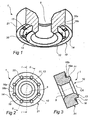
- the pierce nut 1 is designed so as to punch its own hole during the punching operation and to push sheet material into grooves, undercut etc. in the pierce nut during said operation.
- the pierce nut 1 has a centered, threaded through hole 5.
- a pilot 11 protrudes on the underside of the pierce nut, in the following referred to as the engagement side 10.
- the protrusion H of the pilot 11 relatively to the end surface 14 of the other portion on the engagement side 10 depends primarily on the sheet thickness.
- the protrusion H is about 1.2 mm for sheet thicknesses up to about 1.3-1.6 mm and about 0.65 mm for sheet thicknesses up to about 0.7-1.2 mm.
- the pilot 11 has a plane, annular end surface 13 with a punching edge 12 which engages a sheet 4 and a punching die 3 during the actual punching ( figs 6-8 ).
- an annular wall surface 15 is provided which is inclined inwards towards the radial centre CA of the nut and, thus, forms an undercut portion.
- the inclination (angle A) is adapted so that the wall engages the sheet across the entire surface during punching. It has been found that an angle A of about 79 ⁇ 1° ensures an optimal result, in particular with respect to high-strength sheet metal, but also with respect to standard sheet metal.
- Two annular grooves 16a, 16b are provided on the engagement side 10 of the pierce nut 1, between the external wall 21 of the pierce nut and the wall surface 15.
- the grooves 16a, 16b are shaped in such manner that there is a gap between them. Expressed differently, a ridge 17 is formed between the grooves 16a, 16b.
- the first groove, the inner groove 16a is located closest to the wall surface 15 and comprises an arc-shaped bottom portion 19c, an inclined first surface portion 19a with essentially the same inclination (A) as the wall surface 15 of the pilot 11 and a second surface portion 19b which is inclined at an angle B of about 45° to the end surface 13.
- the inclination of the second end portion 19b is adapted so as to reduce the stress to which the pierce nut and the sheet are subjected during punching as the sheet is pushed into the groove 16a, 16b.
- the second groove, the outer groove 16b is located radially outside the inner groove and consists of an inclined fourth surface portion 19d, an arc-shaped bottom portion 19f and an inclined fifth surface portion 19e, with an inclination E relatively to the end surface 13.
- the purpose of this outer groove 16b is to reduce the punching force to make it easier for the sheet 4 to flow into the inner groove 16a.
- the fifth surface portion 19e may have an inclination E of about 45° and be perpendicular to the inclination C of the fourth surface portion 19d.
- the fourth surface portion 19d may have an inclination of 15° and the fifth surface portion 19e an inclination E of 31°.
- an edge 18 is formed between the second surface portion 19b of the inner groove 16a and the fourth surface portion 19d of the outer groove.
- the edge may be pointed.
- the function of the edge 18 is to guide the sheet above all into the inner groove 16a towards the external wall 15 of the pilot 11, but also into the outer groove 16b as the sheet is being deformed during the punching operation, so as to fix the pierce nut.
- the inclined walls of the grooves can be adjusted to achieve this in an optimal manner.
- the advantage of the pointed edge 18 is that essentially the same amount of punching force can be used for high-strength sheet metal as for conventional sheet metal to achieve the same degree of deformation in the sheet during punching.
- the tip of the edge 18 should be positioned at a distance D from a plane including the pilot's end surface 13, which in the embodiment is about 1.2 mm for sheet thicknesses of about 1.3-1.6 mm and about 0.8 for sheet thicknesses of about 0.7-1.2 mm.
- the edge may also be located on a diameter F that is about 1.45 ⁇ 0.1 mm larger than a maximum diameter G of the pilot 11, thereby to obtain the best possible outcome, i.e. a joint with high torque and pull-through resistance.
- the diameter F may be, for example, about 10.9 mm for sheet thicknesses of about 0.7-1.2 mm and about 11 mm for sheet thicknesses of about 1.3-1.6 mm.
- a plurality of recesses 20 may be provided on the engagement side of the pierce nut 1.
- the recesses 20 may be arranged at essentially the same radial distance from the centre CA of the pierce nut and distributed around the pilot 11.
- the recesses 20 are located in the groove 16a, 16b and are evenly distributed along the edge 18.
- the recesses may also be located in the ridge 17, in such manner that the ridge has a plurality of segments arranged around the pilot.
- anti-rotation means can be arranged in the form of recesses or protrusions in any of the surfaces shown, for example the wall surface 15, the surfaces 19a, 19b, 19c, 19d, 19e, 19f in the grooves 16a, 16b, on the ridge 17, in the abutment surface 14 or in the external wall 21.
- Such anti-rotation means allow form-fit locking of the pierce nut to be achieved when the sheet is pushed into the grooves 16a, 16b.
- the sheet is pressed against the edge 18 between the two annular grooves 16a, 16b.
- the edge 18 guides the sheet into the grooves 16a, 16b and the sheet is pushed towards the wall surface 15 of the pilot 11 and forms the geometrical lock by engaging the undercut portion.
- the pierce nut is thus retained in its position both by the form-fit locking and by frictional forces.
- the size of the pilot's end surface 13 may be increased compared with conventional pilots. The result is a more stable process and better protection for the thread in the case of an alignment error between the pierce nut and the punching die.
- the form-fit locking design of the pierce nut allows the dimensions to be reduced and a compact pierce nut geometry is obtained compared with conventional pierce nuts.
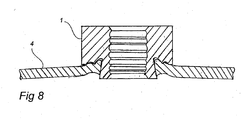
- Figs 6-8 illustrate the punching operation using the pierce nuts 1 described above.
- the punch 2, the pierce nut 1, the sheet 4 and the punching die 3 are positioned at a distance from one another.
- Fig. 7 illustrates the punching operation at the moment when a punching engagement between the pierce nut and the sheet is initiated.
- Fig. 8 shows how the pierce nut 1 has been attached to the sheet 4. It is worth noting how the sheet has been deformed and flowed into the grooves and is retained in its position by the undercut portion formed by pilot 11 and its wall surface 15.
- Figs 9a-9d display the results of measurements of pull-through resistance (push out force) and displacement of the nut-and-sheet joint.
- a conventional M6 pierce nut such as the one shown in EP 0 554 599 B1
- M6 pierce nuts designed according to the present document It appears from fig. 9a that a diameter F of 11 mm offers a considerable improvement over a diameter F of 11.5 mm. It also appears from the graph that both pierce nuts according to the present document offer improvements over the conventional pierce nut.
- the pierce nut with a diameter F of 11.5 mm withstands significantly greater displacement than the conventional pierce nut.
- a conventional M6 pierce nut such as the one shown in EP 0 554 599 B1
- M6 pierce nuts designed according to the present document For this sheet type too, a significant improvement in the ability of the pierce nut to withstand displacement is obtained. It is to be noted that, in this case too, a diameter F of 11 mm offers an improvement over a diameter of 11.5 mm.
- a comparison is made between two M6 pierce nuts designed according to the present document.
- a diameter F of 11 mm offers a major improvement over a diameter F of 11.5 mm.
- Figs 9a-9c thus show that the diameter F is very important for the pull-through resistance of the pierce nut and its ability to withstand displacement, and thereby for optimizing the joint between pierce nut and sheet.
- three different M6 pierce nuts according to the present document are compared with a conventional pierce nut as described in EP 0 554 599 B1 .
- the pierce nuts according to the present document withstand significantly greater displacement than the conventional pierce nut. Moreover, it is noted that an angle A of 79 degrees offers the best combination of pull-through resistance and displacement. A reduction of A to 70 degrees has a smaller negative effect than an increase of A to 82.5 degrees.
- the pierce nut 1 can be essentially circular, as shown in the appended drawings.
- the pilot's wall surface 15 and the grooves 16a, 16b too can be designed in non-circular manner according to the above, which designs can, but do not have to, coincide with the appearance of the external wall 21.
Landscapes
- Engineering & Computer Science (AREA)
- General Engineering & Computer Science (AREA)
- Mechanical Engineering (AREA)
- Connection Of Plates (AREA)
- Automatic Assembly (AREA)
- Forging (AREA)
Claims (19)
- Eine Stanzmutter (1) zum Anbringen an ein plastisch verformbares Metallblech (4), wobei die Stanzmutter aufweist:eine Anlagefläche (14), welche geeignet ist, an dem Metallblech (4) anzuliegen,einen Hinterschnittzapfen (11), der relativ zu der Anlagefläche (14) vorsteht, undeine Senknut (16a, 16b), welche in der Anlagefläche (14) ausgebildet ist und welche zumindest teilweise den Zapfen (11) umgibt, dadurch gekennzeichnet, dass die Nut (16a, 16b) ohne aktive Hinterschnitte ausgebildet ist, welche in Richtung des Zapfens (11) gerichtet sind, wobei die Nut eine innere Nut (16a) und eine äußere Nut (16b) und einen Grat (17) aufweist, welcher dazwischen angeordnet ist, und wobei die äußere Nut (16b) zumindest teilweise durch einen Flächenbereich (19) definiert ist, welcher zu einer Wandfläche (15), die den Zapfen umgibt, und weg von der Stanzmutter gerichtet ist.
- Die Stanzmutter (1) nach Anspruch 1, wobei ein erster Winkel (A) zwischen einer Endfläche (13) des Zapfens (11) und einer Wandfläche (15), welche sich um den Zapfen herum erstreckt, etwa 79±10°, etwa 79±5° oder etwa 79±1° ist.
- Die Stanzmutter (1) nach Anspruch 1 oder 2, wobei die innere Nut (16a) durch einen erste Flächenbereich (19a) definiert ist, welcher, wenn er in einer Schnittebene (I-I) durch das Zentrum (CA) der Stanzmutter und senkrecht zu einer Endfläche (13) des Zapfens (11) betrachtet, im wesentlichen den gleichen Winkel (A) zu der Endfläche (13) zeigt wie eine Wandfläche (15), die den Zapfen umgibt.
- Die Stanzmutter (1) nach einem der Ansprüche 1-3, wobei die innere Nut (16a) durch einen zweiten Flächenbereich (19b) definiert ist, welcher zu dem Zapfen (11) hin orientiert ist und welcher, wenn er in einer Schnittebene (I-I) durch das Zentrum (CA) der Stanzmutter und senkrecht zu einer Endfläche (13) der Stanzmutter gesehen wird, einen zweiten Winkel (B) relativ zu der Endfläche (13) zeigt, welcher zweiter Winkel (B) etwa 35-55° ist, im allgemeinen etwa 40-50° oder etwa 45° ist.
- Die Stanzmutter (1) nach Anspruch 4, wobei die innere Nut (16a) durch einen dritten Flächenbereich (19c) definiert ist, welcher sich zwischen dem ersten und dem zweiten Flächenbereich (19a, 19b) erstreckt.
- Die Stanzmutter (1) nach einem der Ansprüche 1-5, wobei die äußere Nut (16b) durch einen vierten Flächenbereich (19d) definiert ist, welcher von einer Wandfläche (15), die den Zapfen umgibt, weg gerichtet ist und welcher, wenn er in einer Schnittebene (I-I) durch das Zentrum (CA) der Stanzmutter und senkrecht zu einer Endfläche (13) der Stanzmutter gesehen wird, einen dritten Winkel (B) zu der Endfläche (13) zeigt, wobei der dritte Winkel (B) zwischen etwa 15° und etwa 45° ist.
- Die Stanzmutter (1) nach einem der Ansprüche 1-6, wobei der Flächenbereich (19e), welcher zu der Wandfläche (15), die den Zapfen umgibt, hin gerichtet ist und damit die äußere Nut (16b) definiert, ein fünfter Flächenbereich (19) ist, welcher, wenn er in einer Schnittebene (I-I) durch das Zentrum (CA) der Stanzmutter und senkrecht zu einer Endfläche (13) der Stanzmutter gesehen wird, einen vierten Winkel (E) zu der Endfläche (13) zeigt, welcher vierter Winkel (E) zwischen etwa 10° und etwa 70° ist.
- Die Stanzmutter (1) nach Anspruch 6 in Kombination mit Anspruch 7, wobei die äußere Nut (16b) durch einen sechsten Flächenbereich (19f) definiert ist, welcher sich zwischen dem vierten und dem fünften Flächenbereich (19d, 19e) erstreckt.
- Die Stanzmutter (1) nach einem der Ansprüche 3-8, wobei zumindest einer des ersten, zweiten, vierten und fünften Flächenbereichs (19a, 19b, 19d, 19e) derart ausgebildet ist, dass er eine gerade Linie zeigt, die sich durch die Schnittebene (I - I) erstreckt.
- Die Stanzmutter (1) nach Anspruch 9, wobei die gerade Linie in der Schnittebene (I-I) sich im wesentlichen durch den gesamten Flächenbereich (19a, 19b, 19d, 19e) erstreckt.
- die Stanzmutter (1) nach einem der Ansprüche 6-10, wobei der zweite und der vierte Flächenbereich (19b, 19d) miteinander einen Winkel bilden, wenn sie in der Schnittebene (I-I) gesehen werden.
- Die Stanzmutter (1) nach einem der vorangegangenen Ansprüche, wobei die Nut (16a, 16b) den Zapfen (11) umgibt, wobei der Zapfen (11) und die Nut (16a, 16b) im wesentlichen konzentrisch sind.
- Die Stanzmutter (1) nach einem der vorangegangenen Ansprüche, wobei der Grad (17) einen Rand (18) aufweist und wobei der Rand (18) einen Durchmesser (F) hat, der 1,45 mm ± 0,1 mm größer als ein maximaler Durchmesser (G) des Zapfens (11) ist.
- Die Stanzmutter (1) nach Anspruch 13, wobei ein geringster Abstand (D) zwischen einer Ebene, die eine Endfläche (13) der Stanzmutter umfasst, und dem Rand (18) größer oder gleich ist als ein geringster Abstand zwischen der Ebene, welche die Endfläche (13) umfasst, und einer Anlagefläche (14), welche geeignet ist gegen das Metallblech (4) anzuliegen, an welchem die Stanzmutter (1) geeignet ist angebracht zu werden.
- Die Stanzmutter (1) nach Anspruch 14, wobei der geringste Abstand (D) zwischen der Ebene, welche die Endfläche (13) umfasst, und dem Rand (18) zwischen etwa 0,67 und etwa 1,14 mal einer Dicke des Metallblechs (4) ist, an welchem die Stanzmutter (1) geeignet ist angebracht zu werden, zum Beispiel etwa 0,8 mm für Stanzmuttern, die zur Verwendung mit Metallblechen mit einer Dicke von etwa 0,7 mm bis etwa 1,2 mm vorgesehen sind.
- Die Stanzmutter (1) nach Anspruch 14, wobei der geringste Abstand (D) zwischen der Ebene, welche die Endfläche (13) umfasst, und dem Rand (18) zwischen etwa 0,75 und etwa 0,92 mal einer Dicke des Metallblechs (4) ist, an welchem die Stanzmutter (1) geeignet ist angebracht zu werden, zum Beispiel etwa 1,2 mm für Stanzmuttern, die zur Verwendung mit Metallblechen mit einer Dicke von etwa 1,3 mm bis etwa 1,6 mm vorgesehen sind.
- Die Stanzmutter (1) nach einem der vorangegangenen Ansprüche, ferner Anti-Rotationsmittel (20) aufweisend, wobei die Anti-Rotationsmittel (20) in der Nut (16a, 16b) vorgesehen sind.
- Die Stanzmutter (1) nach einem der vorangegangenen Ansprüche, ferner einen inneren Gewindebereich (5) oder einen externen Gewindebereich aufweisen.
- Ein Verfahren zum Montieren eines Befestigungsmittels in einem hochfesten Metallblech (4), wobei das Befestigungsmittel eine Stanzmutter (1) gemäß einem der Ansprüche 1-18 ist.
Applications Claiming Priority (2)
| Application Number | Priority Date | Filing Date | Title |
|---|---|---|---|
| SE0600917A SE530092C2 (sv) | 2006-04-25 | 2006-04-25 | Stansmutter samt användning därav och system innefattande en sådan stansmutter |
| PCT/EP2007/003623 WO2007121998A1 (en) | 2006-04-25 | 2007-04-25 | Pierce nut and use thereof |
Publications (2)
| Publication Number | Publication Date |
|---|---|
| EP2016298A1 EP2016298A1 (de) | 2009-01-21 |
| EP2016298B1 true EP2016298B1 (de) | 2013-08-28 |
Family
ID=38279214
Family Applications (1)
| Application Number | Title | Priority Date | Filing Date |
|---|---|---|---|
| EP07724553.8A Active EP2016298B1 (de) | 2006-04-25 | 2007-04-25 | Stanzmutter und verwendung dafür |
Country Status (5)
| Country | Link |
|---|---|
| EP (1) | EP2016298B1 (de) |
| JP (1) | JP5259575B2 (de) |
| CN (1) | CN101438066B (de) |
| SE (1) | SE530092C2 (de) |
| WO (1) | WO2007121998A1 (de) |
Cited By (1)
| Publication number | Priority date | Publication date | Assignee | Title |
|---|---|---|---|---|
| US9328762B2 (en) | 2012-08-27 | 2016-05-03 | Aoyama Seisakusho Co., Ltd. | Pierce nut for high-strength steel plate |
Families Citing this family (9)
| Publication number | Priority date | Publication date | Assignee | Title |
|---|---|---|---|---|
| US8931990B2 (en) | 2006-04-25 | 2015-01-13 | Stromsholmen Ab | Pierce nut and use thereof |
| DE102009039817A1 (de) * | 2009-09-02 | 2011-03-03 | Profil Verbindungstechnik Gmbh & Co. Kg | Selbststanzendes Mutterelement und Zusammenbauteil bestehend aus dem Mutterelement und einem Blechteil |
| JP3157701U (ja) * | 2009-12-14 | 2010-02-25 | ボーセイキャプティブ株式会社 | かしめナット |
| DE102010032866A1 (de) | 2010-07-30 | 2012-02-02 | Profil Verbindungstechnik Gmbh & Co. Kg | Selbststanzendes Mutterelement und Zusammenbauteil bestehend aus dem Mutterelement und einem Blechteil |
| EP2690293A1 (de) * | 2012-07-27 | 2014-01-29 | Vision Electric GmbH | Einpressmutter |
| JP5986889B2 (ja) * | 2012-10-31 | 2016-09-06 | 東プレ株式会社 | ピアスナット |
| KR101932643B1 (ko) * | 2017-03-17 | 2018-12-27 | 주식회사 성우하이텍 | 판재 접합 너트의 접합장치 |
| CN107081403A (zh) * | 2017-05-31 | 2017-08-22 | 安徽江淮汽车集团股份有限公司 | 压铆冲压模具 |
| CN112412949B (zh) * | 2020-12-01 | 2022-08-12 | 扬州三劦紧固件有限公司 | 一种穿透型紧固螺母 |
Family Cites Families (5)
| Publication number | Priority date | Publication date | Assignee | Title |
|---|---|---|---|---|
| ATE145710T1 (de) * | 1992-01-31 | 1996-12-15 | Multifastener Corp | Selbstsichernde befestigung sowie matrize zu ihrer montage |
| JPH05215115A (ja) * | 1992-01-31 | 1993-08-24 | Tokyo Multi Fastener Kk | ピアスナット |
| US7112142B2 (en) * | 2002-01-22 | 2006-09-26 | Whitesell International Corporation | Method of cold forming a self-attaching female fastener element |
| DE20205192U1 (de) * | 2002-04-03 | 2002-11-07 | Profil Verbindungstechnik GmbH & Co. KG, 61381 Friedrichsdorf | Profil zur Herstellung von Hohlkörperelementen, Hohlkörperelement sowie Zusammenbauteil |
| JP2004205001A (ja) * | 2002-12-26 | 2004-07-22 | Aoyama Seisakusho Co Ltd | ピアスナットの取付構造 |
-
2006
- 2006-04-25 SE SE0600917A patent/SE530092C2/sv unknown
-
2007
- 2007-04-25 EP EP07724553.8A patent/EP2016298B1/de active Active
- 2007-04-25 JP JP2009506974A patent/JP5259575B2/ja active Active
- 2007-04-25 WO PCT/EP2007/003623 patent/WO2007121998A1/en not_active Ceased
- 2007-04-25 CN CN2007800148825A patent/CN101438066B/zh active Active
Cited By (1)
| Publication number | Priority date | Publication date | Assignee | Title |
|---|---|---|---|---|
| US9328762B2 (en) | 2012-08-27 | 2016-05-03 | Aoyama Seisakusho Co., Ltd. | Pierce nut for high-strength steel plate |
Also Published As
| Publication number | Publication date |
|---|---|
| CN101438066A (zh) | 2009-05-20 |
| CN101438066B (zh) | 2012-11-28 |
| EP2016298A1 (de) | 2009-01-21 |
| SE530092C2 (sv) | 2008-02-26 |
| JP2009534612A (ja) | 2009-09-24 |
| JP5259575B2 (ja) | 2013-08-07 |
| SE0600917L (sv) | 2007-10-26 |
| WO2007121998A1 (en) | 2007-11-01 |
Similar Documents
| Publication | Publication Date | Title |
|---|---|---|
| US8931990B2 (en) | Pierce nut and use thereof | |
| EP2016298B1 (de) | Stanzmutter und verwendung dafür | |
| KR100384972B1 (ko) | 리벳팅가능한엘레멘트,앗셈블리,앗셈블리방법및리벳팅다이 | |
| EP3329133B1 (de) | Befestigungselement mit gewinde | |
| US4842466A (en) | Lightweight fastener | |
| EP2069647B1 (de) | Lastanzeigebefestigung und herstellungsverfahren dafür | |
| EP0864766B1 (de) | Zusammenbau von Bauteilen, Verfahren zum Befestigen eines Bauteils auf einem plattenförmigen Körper sowie Prägeform zur Durchführung dieses Verfahrens | |
| EP2787221B1 (de) | Stanzmutter für ein hochfestes stahlblech | |
| US11028868B2 (en) | Press-fit connection between a high-strength component and a press-fit element, method for making such a press-fit connection, and press-fit element for such a press-fit connection | |
| US11773894B2 (en) | Self-clinching fastener | |
| EP1601883B1 (de) | Schneidschraube für die verwendung in gering dehnbaren materialien | |
| US4915559A (en) | Lightweight fastener | |
| US20190316626A1 (en) | One-piece self-locking nut | |
| EP3999746B1 (de) | Selbstschliessendes befestigungselement | |
| CA2967052C (en) | One-piece self-locking nut | |
| EP3168485A1 (de) | Spannungsanzeigescheibe mit versetzten erhebungen und vertiefungen | |
| EP0191501B1 (de) | Gewindeart und Befestigungssystem, bei welchem die Gewindeart verwendet wird | |
| JP2000304010A (ja) | 被固定部材の固定部材への取り付け構造 | |
| JP2019218993A (ja) | ゆるみ防止金属製雄ねじ | |
| US12163548B2 (en) | Self-clinching fastener | |
| KR102916220B1 (ko) | 다목적 파일럿이 있는 셀프-클린칭 및 셀프-피어싱 건축 요소 | |
| EP4590976A1 (de) | Selbstschliessendes befestigungselement | |
| US20230102242A1 (en) | Pierce nut | |
| HK1250500A1 (en) | One-piece self-locking nut |
Legal Events
| Date | Code | Title | Description |
|---|---|---|---|
| PUAI | Public reference made under article 153(3) epc to a published international application that has entered the european phase |
Free format text: ORIGINAL CODE: 0009012 |
|
| 17P | Request for examination filed |
Effective date: 20081124 |
|
| AK | Designated contracting states |
Kind code of ref document: A1 Designated state(s): AT BE BG CH CY CZ DE DK EE ES FI FR GB GR HU IE IS IT LI LT LU LV MC MT NL PL PT RO SE SI SK TR |
|
| AX | Request for extension of the european patent |
Extension state: AL BA HR MK RS |
|
| RIN1 | Information on inventor provided before grant (corrected) |
Inventor name: GAERDSTAM, JOHANNES |
|
| 17Q | First examination report despatched |
Effective date: 20091109 |
|
| DAX | Request for extension of the european patent (deleted) | ||
| GRAP | Despatch of communication of intention to grant a patent |
Free format text: ORIGINAL CODE: EPIDOSNIGR1 |
|
| INTG | Intention to grant announced |
Effective date: 20130514 |
|
| GRAS | Grant fee paid |
Free format text: ORIGINAL CODE: EPIDOSNIGR3 |
|
| GRAA | (expected) grant |
Free format text: ORIGINAL CODE: 0009210 |
|
| AK | Designated contracting states |
Kind code of ref document: B1 Designated state(s): AT BE BG CH CY CZ DE DK EE ES FI FR GB GR HU IE IS IT LI LT LU LV MC MT NL PL PT RO SE SI SK TR |
|
| REG | Reference to a national code |
Ref country code: GB Ref legal event code: FG4D |
|
| REG | Reference to a national code |
Ref country code: CH Ref legal event code: EP |
|
| REG | Reference to a national code |
Ref country code: AT Ref legal event code: REF Ref document number: 629529 Country of ref document: AT Kind code of ref document: T Effective date: 20130915 |
|
| REG | Reference to a national code |
Ref country code: IE Ref legal event code: FG4D |
|
| REG | Reference to a national code |
Ref country code: DE Ref legal event code: R096 Ref document number: 602007032527 Country of ref document: DE Effective date: 20131024 |
|
| REG | Reference to a national code |
Ref country code: AT Ref legal event code: MK05 Ref document number: 629529 Country of ref document: AT Kind code of ref document: T Effective date: 20130828 |
|
| REG | Reference to a national code |
Ref country code: LT Ref legal event code: MG4D |
|
| REG | Reference to a national code |
Ref country code: NL Ref legal event code: VDEP Effective date: 20130828 |
|
| PG25 | Lapsed in a contracting state [announced via postgrant information from national office to epo] |
Ref country code: IS Free format text: LAPSE BECAUSE OF FAILURE TO SUBMIT A TRANSLATION OF THE DESCRIPTION OR TO PAY THE FEE WITHIN THE PRESCRIBED TIME-LIMIT Effective date: 20131228 Ref country code: AT Free format text: LAPSE BECAUSE OF FAILURE TO SUBMIT A TRANSLATION OF THE DESCRIPTION OR TO PAY THE FEE WITHIN THE PRESCRIBED TIME-LIMIT Effective date: 20130828 Ref country code: CY Free format text: LAPSE BECAUSE OF FAILURE TO SUBMIT A TRANSLATION OF THE DESCRIPTION OR TO PAY THE FEE WITHIN THE PRESCRIBED TIME-LIMIT Effective date: 20130724 Ref country code: LT Free format text: LAPSE BECAUSE OF FAILURE TO SUBMIT A TRANSLATION OF THE DESCRIPTION OR TO PAY THE FEE WITHIN THE PRESCRIBED TIME-LIMIT Effective date: 20130828 Ref country code: PT Free format text: LAPSE BECAUSE OF FAILURE TO SUBMIT A TRANSLATION OF THE DESCRIPTION OR TO PAY THE FEE WITHIN THE PRESCRIBED TIME-LIMIT Effective date: 20131230 Ref country code: SE Free format text: LAPSE BECAUSE OF FAILURE TO SUBMIT A TRANSLATION OF THE DESCRIPTION OR TO PAY THE FEE WITHIN THE PRESCRIBED TIME-LIMIT Effective date: 20130828 |
|
| REG | Reference to a national code |
Ref country code: NL Ref legal event code: VDEP Effective date: 20130828 |
|
| PG25 | Lapsed in a contracting state [announced via postgrant information from national office to epo] |
Ref country code: SI Free format text: LAPSE BECAUSE OF FAILURE TO SUBMIT A TRANSLATION OF THE DESCRIPTION OR TO PAY THE FEE WITHIN THE PRESCRIBED TIME-LIMIT Effective date: 20130828 Ref country code: FI Free format text: LAPSE BECAUSE OF FAILURE TO SUBMIT A TRANSLATION OF THE DESCRIPTION OR TO PAY THE FEE WITHIN THE PRESCRIBED TIME-LIMIT Effective date: 20130828 Ref country code: GR Free format text: LAPSE BECAUSE OF FAILURE TO SUBMIT A TRANSLATION OF THE DESCRIPTION OR TO PAY THE FEE WITHIN THE PRESCRIBED TIME-LIMIT Effective date: 20131129 Ref country code: BE Free format text: LAPSE BECAUSE OF FAILURE TO SUBMIT A TRANSLATION OF THE DESCRIPTION OR TO PAY THE FEE WITHIN THE PRESCRIBED TIME-LIMIT Effective date: 20130828 Ref country code: LV Free format text: LAPSE BECAUSE OF FAILURE TO SUBMIT A TRANSLATION OF THE DESCRIPTION OR TO PAY THE FEE WITHIN THE PRESCRIBED TIME-LIMIT Effective date: 20130828 Ref country code: PL Free format text: LAPSE BECAUSE OF FAILURE TO SUBMIT A TRANSLATION OF THE DESCRIPTION OR TO PAY THE FEE WITHIN THE PRESCRIBED TIME-LIMIT Effective date: 20130828 |
|
| PG25 | Lapsed in a contracting state [announced via postgrant information from national office to epo] |
Ref country code: CY Free format text: LAPSE BECAUSE OF FAILURE TO SUBMIT A TRANSLATION OF THE DESCRIPTION OR TO PAY THE FEE WITHIN THE PRESCRIBED TIME-LIMIT Effective date: 20130828 |
|
| PG25 | Lapsed in a contracting state [announced via postgrant information from national office to epo] |
Ref country code: RO Free format text: LAPSE BECAUSE OF FAILURE TO SUBMIT A TRANSLATION OF THE DESCRIPTION OR TO PAY THE FEE WITHIN THE PRESCRIBED TIME-LIMIT Effective date: 20130828 Ref country code: EE Free format text: LAPSE BECAUSE OF FAILURE TO SUBMIT A TRANSLATION OF THE DESCRIPTION OR TO PAY THE FEE WITHIN THE PRESCRIBED TIME-LIMIT Effective date: 20130828 Ref country code: NL Free format text: LAPSE BECAUSE OF FAILURE TO SUBMIT A TRANSLATION OF THE DESCRIPTION OR TO PAY THE FEE WITHIN THE PRESCRIBED TIME-LIMIT Effective date: 20130828 Ref country code: SK Free format text: LAPSE BECAUSE OF FAILURE TO SUBMIT A TRANSLATION OF THE DESCRIPTION OR TO PAY THE FEE WITHIN THE PRESCRIBED TIME-LIMIT Effective date: 20130828 Ref country code: CZ Free format text: LAPSE BECAUSE OF FAILURE TO SUBMIT A TRANSLATION OF THE DESCRIPTION OR TO PAY THE FEE WITHIN THE PRESCRIBED TIME-LIMIT Effective date: 20130828 Ref country code: DK Free format text: LAPSE BECAUSE OF FAILURE TO SUBMIT A TRANSLATION OF THE DESCRIPTION OR TO PAY THE FEE WITHIN THE PRESCRIBED TIME-LIMIT Effective date: 20130828 |
|
| PG25 | Lapsed in a contracting state [announced via postgrant information from national office to epo] |
Ref country code: ES Free format text: LAPSE BECAUSE OF FAILURE TO SUBMIT A TRANSLATION OF THE DESCRIPTION OR TO PAY THE FEE WITHIN THE PRESCRIBED TIME-LIMIT Effective date: 20130828 |
|
| REG | Reference to a national code |
Ref country code: DE Ref legal event code: R097 Ref document number: 602007032527 Country of ref document: DE |
|
| PLBE | No opposition filed within time limit |
Free format text: ORIGINAL CODE: 0009261 |
|
| STAA | Information on the status of an ep patent application or granted ep patent |
Free format text: STATUS: NO OPPOSITION FILED WITHIN TIME LIMIT |
|
| 26N | No opposition filed |
Effective date: 20140530 |
|
| REG | Reference to a national code |
Ref country code: DE Ref legal event code: R097 Ref document number: 602007032527 Country of ref document: DE Effective date: 20140530 |
|
| PG25 | Lapsed in a contracting state [announced via postgrant information from national office to epo] |
Ref country code: LU Free format text: LAPSE BECAUSE OF FAILURE TO SUBMIT A TRANSLATION OF THE DESCRIPTION OR TO PAY THE FEE WITHIN THE PRESCRIBED TIME-LIMIT Effective date: 20140425 Ref country code: MC Free format text: LAPSE BECAUSE OF FAILURE TO SUBMIT A TRANSLATION OF THE DESCRIPTION OR TO PAY THE FEE WITHIN THE PRESCRIBED TIME-LIMIT Effective date: 20130828 |
|
| REG | Reference to a national code |
Ref country code: CH Ref legal event code: PL |
|
| GBPC | Gb: european patent ceased through non-payment of renewal fee |
Effective date: 20140425 |
|
| REG | Reference to a national code |
Ref country code: IE Ref legal event code: MM4A |
|
| PG25 | Lapsed in a contracting state [announced via postgrant information from national office to epo] |
Ref country code: LI Free format text: LAPSE BECAUSE OF NON-PAYMENT OF DUE FEES Effective date: 20140430 Ref country code: GB Free format text: LAPSE BECAUSE OF NON-PAYMENT OF DUE FEES Effective date: 20140425 Ref country code: CH Free format text: LAPSE BECAUSE OF NON-PAYMENT OF DUE FEES Effective date: 20140430 |
|
| REG | Reference to a national code |
Ref country code: FR Ref legal event code: PLFP Year of fee payment: 9 |
|
| PG25 | Lapsed in a contracting state [announced via postgrant information from national office to epo] |
Ref country code: IE Free format text: LAPSE BECAUSE OF NON-PAYMENT OF DUE FEES Effective date: 20140425 |
|
| PG25 | Lapsed in a contracting state [announced via postgrant information from national office to epo] |
Ref country code: MT Free format text: LAPSE BECAUSE OF FAILURE TO SUBMIT A TRANSLATION OF THE DESCRIPTION OR TO PAY THE FEE WITHIN THE PRESCRIBED TIME-LIMIT Effective date: 20130828 |
|
| REG | Reference to a national code |
Ref country code: FR Ref legal event code: PLFP Year of fee payment: 10 |
|
| PG25 | Lapsed in a contracting state [announced via postgrant information from national office to epo] |
Ref country code: BG Free format text: LAPSE BECAUSE OF FAILURE TO SUBMIT A TRANSLATION OF THE DESCRIPTION OR TO PAY THE FEE WITHIN THE PRESCRIBED TIME-LIMIT Effective date: 20130828 |
|
| PG25 | Lapsed in a contracting state [announced via postgrant information from national office to epo] |
Ref country code: TR Free format text: LAPSE BECAUSE OF FAILURE TO SUBMIT A TRANSLATION OF THE DESCRIPTION OR TO PAY THE FEE WITHIN THE PRESCRIBED TIME-LIMIT Effective date: 20130828 Ref country code: HU Free format text: LAPSE BECAUSE OF FAILURE TO SUBMIT A TRANSLATION OF THE DESCRIPTION OR TO PAY THE FEE WITHIN THE PRESCRIBED TIME-LIMIT; INVALID AB INITIO Effective date: 20070425 |
|
| REG | Reference to a national code |
Ref country code: FR Ref legal event code: PLFP Year of fee payment: 11 |
|
| REG | Reference to a national code |
Ref country code: FR Ref legal event code: PLFP Year of fee payment: 12 |
|
| P01 | Opt-out of the competence of the unified patent court (upc) registered |
Effective date: 20230517 |
|
| PGFP | Annual fee paid to national office [announced via postgrant information from national office to epo] |
Ref country code: FR Payment date: 20250318 Year of fee payment: 19 |
|
| PGFP | Annual fee paid to national office [announced via postgrant information from national office to epo] |
Ref country code: IT Payment date: 20250317 Year of fee payment: 19 |
|
| PGFP | Annual fee paid to national office [announced via postgrant information from national office to epo] |
Ref country code: DE Payment date: 20250318 Year of fee payment: 19 |