EP2015993B1 - Wrapping device and method for operating a wrapping device - Google Patents
Wrapping device and method for operating a wrapping device Download PDFInfo
- Publication number
- EP2015993B1 EP2015993B1 EP07730754A EP07730754A EP2015993B1 EP 2015993 B1 EP2015993 B1 EP 2015993B1 EP 07730754 A EP07730754 A EP 07730754A EP 07730754 A EP07730754 A EP 07730754A EP 2015993 B1 EP2015993 B1 EP 2015993B1
- Authority
- EP
- European Patent Office
- Prior art keywords
- wrapping
- ring
- piece
- wrapped
- frame
- Prior art date
- Legal status (The legal status is an assumption and is not a legal conclusion. Google has not performed a legal analysis and makes no representation as to the accuracy of the status listed.)
- Active
Links
- 238000000034 method Methods 0.000 title claims description 6
- 239000000463 material Substances 0.000 claims description 23
- 208000032820 Ring chromosome 13 syndrome Diseases 0.000 description 74
- 238000010276 construction Methods 0.000 description 14
- 229910000831 Steel Inorganic materials 0.000 description 3
- 238000012423 maintenance Methods 0.000 description 3
- 239000010959 steel Substances 0.000 description 3
- 238000004806 packaging method and process Methods 0.000 description 2
- 230000001154 acute effect Effects 0.000 description 1
- 238000005516 engineering process Methods 0.000 description 1
- 230000010354 integration Effects 0.000 description 1
- 239000002184 metal Substances 0.000 description 1
- 238000004804 winding Methods 0.000 description 1
Images


Classifications
-
- B—PERFORMING OPERATIONS; TRANSPORTING
- B65—CONVEYING; PACKING; STORING; HANDLING THIN OR FILAMENTARY MATERIAL
- B65B—MACHINES, APPARATUS OR DEVICES FOR, OR METHODS OF, PACKAGING ARTICLES OR MATERIALS; UNPACKING
- B65B11/00—Wrapping, e.g. partially or wholly enclosing, articles or quantities of material, in strips, sheets or blanks, of flexible material
- B65B11/04—Wrapping, e.g. partially or wholly enclosing, articles or quantities of material, in strips, sheets or blanks, of flexible material the articles being rotated
-
- B—PERFORMING OPERATIONS; TRANSPORTING
- B65—CONVEYING; PACKING; STORING; HANDLING THIN OR FILAMENTARY MATERIAL
- B65B—MACHINES, APPARATUS OR DEVICES FOR, OR METHODS OF, PACKAGING ARTICLES OR MATERIALS; UNPACKING
- B65B25/00—Packaging other articles presenting special problems
- B65B25/24—Packaging annular articles, e.g. tyres
-
- B—PERFORMING OPERATIONS; TRANSPORTING
- B65—CONVEYING; PACKING; STORING; HANDLING THIN OR FILAMENTARY MATERIAL
- B65B—MACHINES, APPARATUS OR DEVICES FOR, OR METHODS OF, PACKAGING ARTICLES OR MATERIALS; UNPACKING
- B65B27/00—Bundling particular articles presenting special problems using string, wire, or narrow tape or band; Baling fibrous material, e.g. peat, not otherwise provided for
- B65B27/06—Bundling coils of wire or like annular objects
Definitions
- the present invention relates to a wrapping device, which includes
- the invention also relates to a method for operating a wrapping device.
- Patent document DE - 1192094 discloses a wrapping device, in which the wrapping ring, which is in a vertical position, moves in the axial direction of the piece being wrapped, in order to feed and remove the pieces being wrapped to and from the wrapping, by utilizing, for example, a portal crane.
- the problem with this construction is that a construction of the type described cannot be utilized in wrapping lines, in which a conveyor apparatus, for example is used to feed and remove the pieces being wrapped.
- US patent 4,829,753 discloses a wrapping-device solution, in which the wrapping ring is on the horizontal plane and opens in a scissors manner.
- This construction permits the pieces being wrapped to be fed directly to the wrapping, for example, utilizing a portal crane.
- the ring structure, which opens in a scissors-like manner does not permit even the slightest movement of the piece being wrapped in the direction of its axis during wrapping. If the piece being wrapped moves during wrapping, the wrapping ring can no longer be opened, due to the limited size of the centre hole of the piece being wrapped.
- the construction described does not permit the pieces being wrapped to be fed to the wrapping on a conveyor apparatus in the direction of its axis.
- the parts of the wrapping ring that opens in a scissors-like manner limit the free space available for the feed of the pieces being wrapped. Thus there is a great risk that during feeding or removal the piece being wrapped will collide with the wrapping ring and damage it.
- Figure 16 of patent application EP - 1 464 579 A2 shows a wrapping device, in which there is a wrapping ring that is in two parts, turning vertically around a pivot point and movably attached to a vertical pillar.
- one of the parts of the ring turns in such a way that an acute angle is formed between the planes formed by the parts.
- the other part of the ring remains inside the centre hole of the piece being wrapped, or at least in its wrapping position, so that the piece can be removed from the rotation space by moving it in the axial direction.
- the partial turning of the wrapping ring does not sufficiently eliminate the risk of damaging the wrapping ring when bringing the pieces being wrapped to the wrapping device and removing them from it.
- a construction with a portal-type frame becomes unavoidably high, so that its structure has considerable stiffness requirements. It is difficult to achieve sufficient stiffness in an open portal structure, without angled supports. An additional difficulty of such a structure is that most of mass of the device and the frame must be placed in the upper part of the frame. Both the feeding of the pieces being wrapped into the wrapping device and their removal from it, as well as the replacement of the wrapping material, demand, on the other hand a structure that is open from one or both sides, with no angled supports. A wrapping ring that is supported from only one side requires sufficient stiffness of the wrapping ring for being able to operate. A wrapping ring with a known construction must be extremely stiff, due the frame structure being located at the end of the device and the great span arising from this. This leads in turn to a large mass that must be moved. In the solutions referred to, the operation of the device requires the operating devices and elements that make operation possible to be generally in the upper part of the device, to which there is easy access is required for maintenance operations.
- the present invention is intended to create a wrapping device with a simple construction, and in connection with which the pieces being wrapped can be handled easily and without difficulty.
- the characteristic features of the wrapping device according to the invention are stated in the accompanying Claim 1.
- the invention also relates to an apparatus for changing the wrapping material and methods for operating the wrapping device and for changing the wrapping-material cartridge, the characteristic features of which are stated in Claims 12, 13, 16, and 17.
- the wrapping ring can be moved out of the centre hole of the piece being wrapping, in order to turn the totality away from the wrapping position.
- the construction of the wrapping device according to the invention is low and open from both above and from the sides.
- the pieces being wrapped can be fed and removed, or stated more generally, changed, without the risk of damaging the wrapping ring, because the space reserved for wrapping is free of the wrapping ring and the surroundings of the space are free of obstacles when examined from every potential direction for feeding the piece.
- the frame structure of the device is sturdy, low, and simple.
- the structure of the wrapping ring is light.
- the service points on the device are easily accessed, without separate or attached service platforms and stairs.
- Pieces being wrapped can be feed to and removed from the device in several different ways.
- the construction which is open from above, permits pieces being wrapped to be fed and removed from directly above. Pieces can also be brought and removed from the front, or also from the sides of the wrapping device.
- the same basic construction can be used in different application solutions.
- the changing of the wrapping-material reel can even be implemented in such a way that the wrapping ring need not be opened and moved away from the wrapping position in connection with changing.
- FIGS 1 and 2 show top views of a first embodiment of the wrapping device 10.
- the wrapping device 10 includes three main components.
- the frame 12 of the wrapping device 10 a wrapping ring 13 arranged to be moved relative to the frame 12, and at least one wrapping head 14 arranged to rotate around the wrapping ring 13.
- the piece being wrapped using the wrapping device 10 can be, for example, a cylindrical reel 15 of sheet metal.
- the piece 15 being wrapped has a centre hole 21, through which the closed wrapping ring 13 runs when wrapping the piece 15 according to Figure 1 .
- the wrapping material 22 can be, for example, a band of plastic or paper, which is intended, for example, to protect the piece 15 during transportation and storage.
- means 11 can also be arranged in connection with the device 10 to rotate the piece 15 around its longitudinal axis 21 during wrapping.
- the means consist of a set of rotation rollers 11.
- the set of rollers 11 consists of two elongated rollers mounted to rotate on shafts, on top of which the cylindrical piece 15 being wrapped can be rotated around its longitudinal axis while wrapping is performed.
- a wrapping ring 13, arranged movably relative to the frame 12, is fitted to the frame 12 of the wrapping device 10.
- the movement of the wrapping ring 13 relative to the frame 12 can be of many kinds.
- the wrapping ring 13 is pivoted rotatably to the frame 12 at pivot points 16.1, 16.2.
- other ways of implementing the turning are also possible.
- the wrapping ring 13 in the horizontal position is attached to the frame 12 at two or more pivot points 16.1, 16.2, in such a way that it can be turned around its horizontal axis of rotation 37 entirely away from above the rotation rollers 11, in other words from the wrapping position of the wrapping ring 13.
- the wrapping ring 13 will then be entirely removed from the potential feed and removal routes of the pieces 15 being wrapped. This will prevent possible collisions that will damage the device 10 when feeding the pieces 15 to wrapping, or removing them from wrapping.
- a lifting mechanism 24 ( Figure 4 ) in the frame 12 around the pivot points 16.1, 16.2.
- the wrapping-ring structure 13 pivoted in the manner described also permits the pieces 15 being wrapped to be fed to wrapping and removed from it in the direction of the longitudinal axis of the piece 15.
- pivoting the wrapping ring 13 horizontally on top of the frame 12 is the wrapping position, the frame 12 remains surprisingly low, so that the structure can also be implemented to be sufficiently stiff.
- the support of the wrapping ring 13 from several pivot point 16.1, 16.2 at a distance to each other significantly reduces the free span of the ring 13 and thus makes the ring structure 13 sturdy.
- the ring 13 can be directly pivoted to the frame 12 from the long side 25.2 next to the frame 12, or it can be attached to a rotation beam 29, which is pivoted to the frame 12.
- the long side 25.2 of the ring 13 is able to slide in the rotation beam 29 (for example, in a slide-rail arrangement).
- the wrapping ring 13 which is pivoted from one, mainly straight, elongated side 25.2 to the frame 12, acts as a guide for the wrapping head 14, which can be arranged to rotate around it.
- the wrapping ring 13 is in the wrapping position, when it is on the horizontal plane.
- the wrapping ring 13 is arranged to move through the axial centre opening 21 of the piece being wrapped, so that the wrapping material 22 can be wrapped by the wrapping head 14 around the piece, along a path 35 ( Figure 5 ) running through the centre hole 21.
- the wrapping head 14 can be equipped with an operating device, with the aid of which the wrapping head 14 moves the wrapping ring 13 along an continuous closed track 39 formed for it, winding the wrapping material 22 around the piece 15 being wrapped.
- the track 39 can be oval in shape, but it can also be, for example, a rectangle with suitably rounded corners.
- the shape of the track 39 ensures the tension of the wrapping material 22 over the entire length of the wrapping ring 13.
- the wrapping ring 13 can be moved away from inside the centre hole 21 of the piece 15 being wrapped. In that case too, the wrapping ring 13 moves relative to the frame 12. This makes it possible to move the wrapping ring 13 by turning it entirely away from the rotation space 20 reserved for the piece 15 being wrapped, where it is in the wrapping position. Moving takes place by turning the wrapping ring 13 vertically away from the rotation space 20. Raising the wrapping ring 13 by turning it permits the pieces 15 being wrapped to be fed and removed without risk of damage to the wrapping device 10. Thus, the actual wrapping device 10 itself can be moved relative to the pieces being wrapped, in order to take a new piece for wrapping.
- the moving of the entire wrapping ring 13 away from the wrapping position can be implemented using several different constructions.
- the wrapping ring 13 in an openable structure.
- the device 10 includes a transfer mechanism 23 that creates a movement in the wrapping ring 13 in the axial direction of the piece 15 being wrapped.
- the wrapping ring's 13 part 13' which is in the centre hole 21 of the piece 15 being wrapped, can be moved out of the centre hole 21.
- the wrapping ring's 13 part 13', which is in the centre hole 21 of the piece 15 being wrapped can be the long side 25.1 of the wrapping ring 13, which is in the axial direction of the piece 15, which is inside the centre hole 21 during wrapping.
- the side 25.1 of the wrapping ring 13 is the outermost side of the device 10 and is opposite to the side 25.2 of the wrapping ring 13 pivoted to the frame 12. At least the side 25.1 of the ring 13 can be moved linearly, by a transfer mechanism 23, away from inside the centre hole 21, in the axial direction of the piece 15.
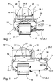
- Figures 1 - 3 show a first embodiment for implementing the wrapping ring 13, following the basic principle of the invention.
- Figure 1 shows a top view when the wrapping ring 13 is closed
- Figure 2 shows a top view when the wrapping ring 13 is open
- Figure 3 shows a front view when the wrapping ring 13 is open.
- the wrapping ring 13 is divided into two parts, 13.1, 13.2 on both of its long sides 25.1, 25.2.
- At least one of the half rings 13.1, 13.2, and in this case both half rings 13.1, 13.2 can be moved in opposite directions in the horizontal plane, i.e. out from inside the centre hole 21 in the axial direction of the piece 15 being wrapped, when the ring 13 is in the wrapping position.
- At least one 26.1 of the meeting points 26.1 26.2 of the parts 13.1, 13.2 is inside the centre hole 21, when the ring 13 is closed.
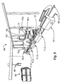
- FIG 4 shows a side view of the wrapping device 10, illustrating the turning movement of the wrapping ring 13 around its pivot points 16.1, 16.2.
- the wrapping ring 13 is shown by broken lines when it is away from the wrapping position, i.e. from the rotation position 20.
- the device 10 surprisingly forms a device totality that is open from above.
- two shaft flanges 38 from which the ring 13 is pivoted to the frame 12, are mounted in bearings on the upper surface 31 of the frame 12.
- a lifting mechanism 32 33 in order to create a vertical lifting movement in the wrapping ring 13 and thus also in the frame 12, on top of which is the ring 13.
- the lifting mechanism 32, 33 can affect the height position of each corner of the frame 12 independently of each other. Thus it can be used to seek for a suitable position for the wrapping ring 13 relative to the centre hole 21 of the piece 15.
- Figure 5 shows the wrapping device 10 shown in Figures 1 - 4 , in which the open wrapping ring 13 is being either lowered to the horizontal wrapping position, or raised vertically away from the wrapping position to the position for changing the piece 15 being wrapped. Lowering and raising take place by turning the wrapping ring 13 around its side pivoted to the frame 12.
- Figure 5 shows very clearly the pivoting of the ring 13 to the frame 12 of the device 10. The ring 13 is well supported on the frame 12, because it is pivoted to the frame 12 from its long side 25.2.
- a rotation and wrapping space 20 is reserved above it for the piece 15 being wrapped.
- the space must be free enough for the wrapping to be able to be performed without obstacles, relative to both the rotation of the piece 15 and to the movement of the wrapping head 14.
- the set of rotation rollers 11 can be, for example, installed permanently in connection with the device 10, or also of a moving type, such as that shown in Figures 3 and 4 . In that case, the set of rotation rollers 11 can move, for example, in the direction of the longitudinal axis of the piece 15, or also at right angles to the longitudinal axis of the piece 15.
- a moving set of rotation rollers 11 can be used, for example, to move the piece 15 to the wrapping device 10 and to remove it from the wrapping device 10. No separate conveyor track, along which the piece 15 to be wrapped would be brought and removed, need be arranged in connection with the device 10. This simplifies the implementation and reduces the investment costs of the wrapping arrangement.
- Figures 3 and 4 also show the base 11', equipped with wheels, of the set of rotation rollers 11, which is not shown at all in Figures 1 and 2 for reasons of clarity.
- the device 10 is also equipped with wheels 28, but it can also be installed in a fixed manner.
- FIG 6 shows a perspective view of one example of a system 34 applying a wrapping device according to Figures 1 - 4 .
- the system can be, for example, in connection with a steel mill, in which steel made into a sheet form is manufactured and reeled into compact cylinders with a centre hole, and which is then packed using the device 10 according to the invention.
- Such a system 34 for wrapping pieces 15 with a centre hole includes a wrapping device 10, a possible changing apparatus 17 for changing the wrapping-material cartridges 30, and means 11 for rotating the pieces 15.1 - 15.3 around their central axes 21.
- the means for rotating the pieces 15.1 - 15.3 around their central axes 21 now consist of a group of rotating devices 11.1 - 11.5.
- the wrapping device 10 and the group of rotating devices 11.1 - 11.5 are, in addition, arranged to be movable relative to each other using the rotation devices 11.1 - 11.5 in order to use a single wrapping device 10 to wrap the pieces 15.1 - 15.3 being rotated.
- the wrapping device 10 can be equipped with a transfer device 28 ( Figure 4 ), in order to move it from one rotation device to another.
- the rotation device 11.1 - 11.5 too, or at least some of them can be equipped with transfer means 35 ( Figures 3 and 4 ), for bringing the piece 15 being wrapped into connection with the wrapping device 10 and for moving away from connection with the wrapping device 10.
- Figure 6 shows precisely such an embodiment.
- the transfer means 35 are arranged to move the rotation device 11 freely in the desired direction.
- the rotation device 11 can operate, for example, as an automatically guided trolley.
- FIG. 7 shows a rough schematic drawing of a second embodiment for removing the ring structure 13 from inside the centre hole 21.
- the bayonet 13' connects the open ends 27.1, 27.2 of the wrapping ring through the centre hole 21 of the piece 15 being wrapped.
- the bayonet component 13' which is inside the centre hole 21 of the piece 15 being wrapped, forms one of the long sides 25.1 of the wrapping ring 13, which can again be moved using a transfer mechanism 21 linearly, in the axial direction of the piece 15 being wrapped, out from inside the centre hole 21 and into the centre hole 21.
- the bayonet component 13' can be a telescopic, or elongated structure as shown in Figure 7 , extending outside the ring 13 when it opens.
- Figure 8 shows a third embodiment of the ring structure 13 when the ring 13 is open.
- the wrapping ring 13 is divided into two parts 13.1, 13.2 on both of its long sides 25.1, 25.2. At least one of the parts 13.1, 13.2 and now only the second part 13.2 can be moved by the transfer mechanism 23 out from inside the centre hole 21, in the axial direction of the piece 15.
- the wrapping head 13 is divided into two parts 13.1, 13.2 on its long sides 25.1, 25.2, in such a way that, when the wrapping ring 13 is closed, both meeting points 26.1, 26.2 of the ring halves 13.1, 13.2 are outside the centre hole 21. Thus the meeting points 26.1, 26.2 are on the side of the half 13.2 that does not move.
- the ring half 13.2 of the side 25.1 inside the centre hole 21 is moved axially to the right, when the side 25.1 in question will move entirely out of the centre 21.
- both ring halves 13.1, 13.2 are turned vertically relative to the pivot point 16.1, 16.2, so that they rise to point upwards at a slant and thus leave the wrapping position.
- the invention also relates to a method for operating a wrapping device 10.
- the device 10 can be implemented with several different ways of operation.
- the basic operation of the device 10 can be, for example, as follows.
- the wrapping ring 13 can be initially opened, as shown in Figures 2 and 3 and turned away from the wrapping space 20, for the feeding of the pieces being wrapped (the wrapping ring 13 in broken lines in Figure 4 ).
- the piece 15 being wrapped can then be brought onto the rotation rollers 11 freely from the chosen direction.
- the open wrapping ring 13 is lowered to the wrapping position (the wrapping ring 13 in solid lines in Figure 4 and the arrangement according to Figure 2 ).
- the lifting-movement mechanism 32, 33 in the frame part 12 of the device 10 is used to align the wrapping ring 13 with the level of the centre hole 21 of the piece 15 being wrapped.
- the wrapping ring 13 can be closed, when the ring halves 13.1, 13.2 move towards each other. As a result of closing, the wrapping ring 13 forms a closed track 39 for the wrapping head 14 (the arrangement according to Figure 1 ).
- the end of the wrapping material 22 is pressed against the piece 15 being wrapped, or else the operator of the device 10 attaches the end manually to the piece 15 being wrapped.
- the wrapping device 10 starts automatically, or else is started by the operator.
- the wrapping head 14 starts to rotate, at the same time wrapping the wrapping material 22 from at least one reel 30 along the track 39 formed by the wrapping ring 13 in the horizontal wrapping position and running through the centre hole 21 of the piece 15. Simultaneously the set of rotation rollers 11 rotates the piece 15 being wrapped around its central axis in synchronization with the speed of the wrapping head 14.
- the wrapping is stopped by cutting the wrapping material 22 and attaching the end of the wrapping material 22 to the piece 15 being wrapped.
- the attaching and cutting can take place automatically, or by the action of the operator.
- the wrapping ring 13 is removed from the wrapping space 20 reserved for the piece 15 being wrapped in the opposite order to that of the operations performed before starting wrapping.
- the wrapping ring 13 that is closed in Figure 1 is opened by moving the halves 13.1, 13.2 of the wrapping ring 13 in opposite directions out from inside the centre hole 21 of the piece 15 being wrapped, as a result of which the wrapping ring 13 reaches the open position shown in Figure 2 .
- the wrapping ring 13, which has been opened, i.e. removed from inside the centre hole 21 of the piece 15, is moved entirely away from the wrapping position by raising it vertically to remove the wrapped piece 15 and feed a new piece.
- the wrapping device 10 can also be used together with a conveyor device, or a set of movable rotation rollers 11 and/or the wrapping device 10 itself can be movable, so that several different alternative ways of moving can be implemented in connection with the changing of the piece in the wrapping device 10.
- the wrapped piece 15 can be removed in the chosen direction and a new piece brought to the wrapping space 20.
- the wrapping ring 13 can be closed again by bringing into the centre hole 21 and beginning wrapping as described above.
- Figures 4 - 7 show an embodiment, in which there is also a wrapping-film reel changing device 17, which can also be integrated in the wrapping device 10 according to the invention.
- the operation of the wrapping-reel 30 changing apparatus 17 in connection with the device 10 is particularly smooth.
- a wrapping-material cartridge 30, for example, a wrapping-material reel 30 can be changed at the wrapping head 14 of the wrapping device 10.
- the horizontal wrapping-ring structure 13 in the wrapping position permits, for example, the integration of an automatic wrapping-monitor device 17 on top of the frame structure 12 arranged to move vertically.
- the low frame structure 12 also permits the maintenance points of the wrapping device 10 to be placed in such a way that they are easily accessible without special service platforms and stairs.
- the frame structure 12 permits the changing apparatus 17 to follow the movement of the wrapping ring 13 in the height direction, in such a way that they are always at the same level. There is therefore no need for a separate lifting apparatus to arrange the position of the changing apparatus 17 in the height direction to suit the wrapping ring 13.
- the reel-changing mechanism of the changing apparatus 17 can be implemented, for example, by applying some robot technology that is, as such, known.
Description
- The present invention relates to a wrapping device, which includes
- a frame,
- a wrapping ring arranged to move relative to the frame, and which, in the wrapping position, is arranged to travel through the centre hole of the piece being wrapped, and which, in the vertical direction, can be at least partly moved away from the wrapping position, in order to change the piece being wrapped, and
- a wrapping head arranged to rotate around the wrapping ring, in order to wrap the wrapping material around the piece.
- In addition, the invention also relates to a method for operating a wrapping device.
- There are several known solutions for wrapping cylindrical pieces with a centre hole. Such are disclosed in, among others, the patent documents
DE - 1192094 ,US - 4,829,753 ,WO - 01/42085 A1 WO - 95/21796 EP - 1 253 083 A1 ,AU - 9224506 WO - 03/09311 A1 EP - 0 936 142 A2 ,EP - 0 544 312 ,US - 6,688,076 B1 , andEP - 1 464 579 A2 . - Patent document
DE - 1192094 discloses a wrapping device, in which the wrapping ring, which is in a vertical position, moves in the axial direction of the piece being wrapped, in order to feed and remove the pieces being wrapped to and from the wrapping, by utilizing, for example, a portal crane. The problem with this construction is that a construction of the type described cannot be utilized in wrapping lines, in which a conveyor apparatus, for example is used to feed and remove the pieces being wrapped. -
US patent 4,829,753 discloses a wrapping-device solution, in which the wrapping ring is on the horizontal plane and opens in a scissors manner. This construction permits the pieces being wrapped to be fed directly to the wrapping, for example, utilizing a portal crane. However, the ring structure, which opens in a scissors-like manner, does not permit even the slightest movement of the piece being wrapped in the direction of its axis during wrapping. If the piece being wrapped moves during wrapping, the wrapping ring can no longer be opened, due to the limited size of the centre hole of the piece being wrapped. In addition, the construction described does not permit the pieces being wrapped to be fed to the wrapping on a conveyor apparatus in the direction of its axis. The parts of the wrapping ring that opens in a scissors-like manner limit the free space available for the feed of the pieces being wrapped. Thus there is a great risk that during feeding or removal the piece being wrapped will collide with the wrapping ring and damage it. - Figure 16 of patent application
EP - 1 464 579 A2 shows a wrapping device, in which there is a wrapping ring that is in two parts, turning vertically around a pivot point and movably attached to a vertical pillar. In the construction described, one of the parts of the ring turns in such a way that an acute angle is formed between the planes formed by the parts. The other part of the ring remains inside the centre hole of the piece being wrapped, or at least in its wrapping position, so that the piece can be removed from the rotation space by moving it in the axial direction. Implemented as described, it is difficult to achieve sufficient stiffness in the wrapping ring and its attachment, due to the large span of the wrapping ring when it is opened. The partial turning of the wrapping ring does not sufficiently eliminate the risk of damaging the wrapping ring when bringing the pieces being wrapped to the wrapping device and removing them from it. - In patent documents
WO - 01/42085 EP - 0 936 142 A2 , a vertically positioned wrapping ring is fitted in a portal-type frame. In the solution according toEP - 0 544 312 , the ring is supported from one side on a frame located at the end of the device. A wrapping ring set in a vertical position in the ways described makes the wrapping device high. This leads to several drawbacks in the frame and ring-structure solutions and, in addition, in the operation and maintenance of the device. - A construction with a portal-type frame becomes unavoidably high, so that its structure has considerable stiffness requirements. It is difficult to achieve sufficient stiffness in an open portal structure, without angled supports. An additional difficulty of such a structure is that most of mass of the device and the frame must be placed in the upper part of the frame. Both the feeding of the pieces being wrapped into the wrapping device and their removal from it, as well as the replacement of the wrapping material, demand, on the other hand a structure that is open from one or both sides, with no angled supports. A wrapping ring that is supported from only one side requires sufficient stiffness of the wrapping ring for being able to operate. A wrapping ring with a known construction must be extremely stiff, due the frame structure being located at the end of the device and the great span arising from this. This leads in turn to a large mass that must be moved. In the solutions referred to, the operation of the device requires the operating devices and elements that make operation possible to be generally in the upper part of the device, to which there is easy access is required for maintenance operations.
- One drawback of the aforementioned wrapping-device solutions is that their construction, which is closed from above, does not permit the pieces being wrapped to be brought directly for wrapping, for example, utilizing a roof crane in the packaging area of the factory. Wrapping devices like those described always require a transfer apparatus, by means of which either the piece being wrapped is transferred to the wrapping device, or the wrapping device is moved over the piece being wrapped. In addition, the automatic changing of the wrapping-material reel requires the wrapping ring to be opened and moved, either upwards or to the side. After this, the wrapping ring must be closed and the wrapping head run to the changing position. In addition, the continuation of wrapping requires the operations described to be repeated, in such a way that the wrapping ring becomes once again closed through the centre hole of the piece being wrapped. The performance of these operations demands a great deal of time, so that the wrapping device does not operate efficiently.
- The present invention is intended to create a wrapping device with a simple construction, and in connection with which the pieces being wrapped can be handled easily and without difficulty. The characteristic features of the wrapping device according to the invention are stated in the accompanying Claim 1. In addition, the invention also relates to an apparatus for changing the wrapping material and methods for operating the wrapping device and for changing the wrapping-material cartridge, the characteristic features of which are stated in
Claims - In the wrapping device according to the invention, the wrapping ring can be moved out of the centre hole of the piece being wrapping, in order to turn the totality away from the wrapping position.
- The construction of the wrapping device according to the invention is low and open from both above and from the sides. The pieces being wrapped can be fed and removed, or stated more generally, changed, without the risk of damaging the wrapping ring, because the space reserved for wrapping is free of the wrapping ring and the surroundings of the space are free of obstacles when examined from every potential direction for feeding the piece. The frame structure of the device is sturdy, low, and simple. The structure of the wrapping ring is light. The service points on the device are easily accessed, without separate or attached service platforms and stairs.
- Pieces being wrapped can be feed to and removed from the device in several different ways. The construction, which is open from above, permits pieces being wrapped to be fed and removed from directly above. Pieces can also be brought and removed from the front, or also from the sides of the wrapping device. The same basic construction can be used in different application solutions.
- In the wrapping device according to the invention, the changing of the wrapping-material reel can even be implemented in such a way that the wrapping ring need not be opened and moved away from the wrapping position in connection with changing.
- The invention, which is not restricted to the embodiments described in the following, is examined in greater detail with reference to the accompanying drawings, in which
- Figure 1
- shows a top view of the wrapping device, with the wrapping ring closed,
- Figure 2
- shows a top view of the wrapping device, with the wrapping ring open,
- Figure 3
- shows a front view of the wrapping device, with the wrapping ring open,
- Figure 4
- shows a side view of the wrapping device, illustrating the movement of the wrapping ring around its pivot point,
- Figure 5
- shows a perspective view of the wrapping device of
Figures 1 - 4 , - Figure 6
- shows a perspective view of the arrangement according to the invention, when applying the wrapping device according to
Figures 1-4 , - Figure 7
- shows a top view of a second example of an application for opening the wrapping ring, and
- Figure 8
- shows a top view of a third example of an application for opening the wrapping ring.
-
Figures 1 and 2 show top views of a first embodiment of thewrapping device 10. Thewrapping device 10 includes three main components. Theframe 12 of thewrapping device 10, awrapping ring 13 arranged to be moved relative to theframe 12, and at least onewrapping head 14 arranged to rotate around thewrapping ring 13. The piece being wrapped using thewrapping device 10 can be, for example, acylindrical reel 15 of sheet metal. Thepiece 15 being wrapped has acentre hole 21, through which theclosed wrapping ring 13 runs when wrapping thepiece 15 according toFigure 1 . The wrappingmaterial 22 can be, for example, a band of plastic or paper, which is intended, for example, to protect thepiece 15 during transportation and storage. - Operationally, means 11 can also be arranged in connection with the
device 10 to rotate thepiece 15 around itslongitudinal axis 21 during wrapping. In the case according to the embodiment described, the means consist of a set ofrotation rollers 11. In this case, the set ofrollers 11 consists of two elongated rollers mounted to rotate on shafts, on top of which thecylindrical piece 15 being wrapped can be rotated around its longitudinal axis while wrapping is performed. - A wrapping
ring 13, arranged movably relative to theframe 12, is fitted to theframe 12 of thewrapping device 10. The movement of thewrapping ring 13 relative to theframe 12 can be of many kinds. The wrappingring 13 is pivoted rotatably to theframe 12 at pivot points 16.1, 16.2. Besides pivoting, other ways of implementing the turning are also possible. In the wrapping position according toFigure 1 , the wrappingring 13 in the horizontal position is attached to theframe 12 at two or more pivot points 16.1, 16.2, in such a way that it can be turned around its horizontal axis ofrotation 37 entirely away from above therotation rollers 11, in other words from the wrapping position of thewrapping ring 13. The wrappingring 13 will then be entirely removed from the potential feed and removal routes of thepieces 15 being wrapped. This will prevent possible collisions that will damage thedevice 10 when feeding thepieces 15 to wrapping, or removing them from wrapping. In order to turn thewrapping ring 13 vertically, there is a lifting mechanism 24 (Figure 4 ) in theframe 12 around the pivot points 16.1, 16.2. - The wrapping-
ring structure 13 pivoted in the manner described also permits thepieces 15 being wrapped to be fed to wrapping and removed from it in the direction of the longitudinal axis of thepiece 15. By pivoting thewrapping ring 13 horizontally on top of theframe 12 is the wrapping position, theframe 12 remains surprisingly low, so that the structure can also be implemented to be sufficiently stiff. The support of thewrapping ring 13 from several pivot point 16.1, 16.2 at a distance to each other (thus, in this case from at least two points) significantly reduces the free span of thering 13 and thus makes thering structure 13 sturdy. Thering 13 can be directly pivoted to theframe 12 from the long side 25.2 next to theframe 12, or it can be attached to arotation beam 29, which is pivoted to theframe 12. The long side 25.2 of thering 13 is able to slide in the rotation beam 29 (for example, in a slide-rail arrangement). - The wrapping
ring 13, which is pivoted from one, mainly straight, elongated side 25.2 to theframe 12, acts as a guide for the wrappinghead 14, which can be arranged to rotate around it. When wrapping is performed, the wrappingring 13 is in the wrapping position, when it is on the horizontal plane. In that case, the wrappingring 13 is arranged to move through the axial centre opening 21 of the piece being wrapped, so that the wrappingmaterial 22 can be wrapped by the wrappinghead 14 around the piece, along a path 35 (Figure 5 ) running through thecentre hole 21. The wrappinghead 14 can be equipped with an operating device, with the aid of which the wrappinghead 14 moves thewrapping ring 13 along an continuousclosed track 39 formed for it, winding the wrappingmaterial 22 around thepiece 15 being wrapped. Thetrack 39 can be oval in shape, but it can also be, for example, a rectangle with suitably rounded corners. The shape of thetrack 39 ensures the tension of the wrappingmaterial 22 over the entire length of thewrapping ring 13. - The wrapping
ring 13 can be moved away from inside thecentre hole 21 of thepiece 15 being wrapped. In that case too, the wrappingring 13 moves relative to theframe 12. This makes it possible to move thewrapping ring 13 by turning it entirely away from therotation space 20 reserved for thepiece 15 being wrapped, where it is in the wrapping position. Moving takes place by turning thewrapping ring 13 vertically away from therotation space 20. Raising thewrapping ring 13 by turning it permits thepieces 15 being wrapped to be fed and removed without risk of damage to thewrapping device 10. Thus, theactual wrapping device 10 itself can be moved relative to the pieces being wrapped, in order to take a new piece for wrapping. - The moving of the
entire wrapping ring 13 away from the wrapping position can be implemented using several different constructions. The wrappingring 13 in an openable structure. For moving, thedevice 10 includes atransfer mechanism 23 that creates a movement in thewrapping ring 13 in the axial direction of thepiece 15 being wrapped. By means of it, at least the wrapping ring's 13part 13', which is in thecentre hole 21 of thepiece 15 being wrapped, can be moved out of thecentre hole 21. The wrapping ring's 13part 13', which is in thecentre hole 21 of thepiece 15 being wrapped, can be the long side 25.1 of thewrapping ring 13, which is in the axial direction of thepiece 15, which is inside thecentre hole 21 during wrapping. The side 25.1 of thewrapping ring 13 is the outermost side of thedevice 10 and is opposite to the side 25.2 of thewrapping ring 13 pivoted to theframe 12. At least the side 25.1 of thering 13 can be moved linearly, by atransfer mechanism 23, away from inside thecentre hole 21, in the axial direction of thepiece 15. -
Figures 1 - 3 show a first embodiment for implementing thewrapping ring 13, following the basic principle of the invention.Figure 1 shows a top view when thewrapping ring 13 is closed, whileFigure 2 shows a top view when thewrapping ring 13 is open, andFigure 3 shows a front view when thewrapping ring 13 is open. Now thewrapping ring 13 is divided into two parts, 13.1, 13.2 on both of its long sides 25.1, 25.2. At least one of the half rings 13.1, 13.2, and in this case both half rings 13.1, 13.2, can be moved in opposite directions in the horizontal plane, i.e. out from inside thecentre hole 21 in the axial direction of thepiece 15 being wrapped, when thering 13 is in the wrapping position. At least one 26.1 of the meeting points 26.1 26.2 of the parts 13.1, 13.2 is inside thecentre hole 21, when thering 13 is closed. -
Figure 4 shows a side view of thewrapping device 10, illustrating the turning movement of thewrapping ring 13 around its pivot points 16.1, 16.2. InFigure 4 , the wrappingring 13 is shown by broken lines when it is away from the wrapping position, i.e. from therotation position 20. In this case, thedevice 10 surprisingly forms a device totality that is open from above. For the pivot points 16.1, 16.2, twoshaft flanges 38, from which thering 13 is pivoted to theframe 12, are mounted in bearings on theupper surface 31 of theframe 12. In theframe 12 of thedevice 10, there is, in addition, alifting mechanism 32 33, in order to create a vertical lifting movement in thewrapping ring 13 and thus also in theframe 12, on top of which is thering 13. Thelifting mechanism frame 12 independently of each other. Thus it can be used to seek for a suitable position for thewrapping ring 13 relative to thecentre hole 21 of thepiece 15. -
Figure 5 shows thewrapping device 10 shown inFigures 1 - 4 , in which theopen wrapping ring 13 is being either lowered to the horizontal wrapping position, or raised vertically away from the wrapping position to the position for changing thepiece 15 being wrapped. Lowering and raising take place by turning thewrapping ring 13 around its side pivoted to theframe 12.Figure 5 shows very clearly the pivoting of thering 13 to theframe 12 of thedevice 10. Thering 13 is well supported on theframe 12, because it is pivoted to theframe 12 from its long side 25.2. - When the set of
rotation rollers 11 is in connection with thedevice 10 in the wrapping position, a rotation and wrappingspace 20 is reserved above it for thepiece 15 being wrapped. The space must be free enough for the wrapping to be able to be performed without obstacles, relative to both the rotation of thepiece 15 and to the movement of the wrappinghead 14. - The set of
rotation rollers 11 can be, for example, installed permanently in connection with thedevice 10, or also of a moving type, such as that shown inFigures 3 and 4 . In that case, the set ofrotation rollers 11 can move, for example, in the direction of the longitudinal axis of thepiece 15, or also at right angles to the longitudinal axis of thepiece 15. A moving set ofrotation rollers 11 can be used, for example, to move thepiece 15 to thewrapping device 10 and to remove it from thewrapping device 10. No separate conveyor track, along which thepiece 15 to be wrapped would be brought and removed, need be arranged in connection with thedevice 10. This simplifies the implementation and reduces the investment costs of the wrapping arrangement.Figures 3 and 4 also show the base 11', equipped with wheels, of the set ofrotation rollers 11, which is not shown at all inFigures 1 and 2 for reasons of clarity. In this case, thedevice 10 is also equipped withwheels 28, but it can also be installed in a fixed manner. -
Figure 6 shows a perspective view of one example of asystem 34 applying a wrapping device according toFigures 1 - 4 . The system can be, for example, in connection with a steel mill, in which steel made into a sheet form is manufactured and reeled into compact cylinders with a centre hole, and which is then packed using thedevice 10 according to the invention. Such asystem 34 for wrappingpieces 15 with a centre hole includes awrapping device 10, a possible changingapparatus 17 for changing the wrapping-material cartridges 30, and means 11 for rotating the pieces 15.1 - 15.3 around theircentral axes 21. The means for rotating the pieces 15.1 - 15.3 around theircentral axes 21 now consist of a group of rotating devices 11.1 - 11.5. Thewrapping device 10 and the group of rotating devices 11.1 - 11.5 are, in addition, arranged to be movable relative to each other using the rotation devices 11.1 - 11.5 in order to use asingle wrapping device 10 to wrap the pieces 15.1 - 15.3 being rotated. - The relative movement of the
wrapping device 10 and the rotation devices 11.1 - 11.5 can be arranged in very many different ways. According to one embodiment, thewrapping device 10 can be equipped with a transfer device 28 (Figure 4 ), in order to move it from one rotation device to another. Besides, or instead of thewrapping device 10, the rotation device 11.1 - 11.5 too, or at least some of them can be equipped with transfer means 35 (Figures 3 and 4 ), for bringing thepiece 15 being wrapped into connection with thewrapping device 10 and for moving away from connection with thewrapping device 10.Figure 6 shows precisely such an embodiment. According to one embodiment, the transfer means 35 are arranged to move therotation device 11 freely in the desired direction. Thus therotation device 11 can operate, for example, as an automatically guided trolley. In the embodiment according toFigure 6 , there arerails 40 on the floor of the wrapping hall, along which the rotation devices 11.1 - 11.5 move linearly in a single line. The steel coils 15' awaiting packaging are moved using onto and away from the rotation devices 11.1 - 11.5 using, for example, aportal crane 36. -
Figure 7 shows a rough schematic drawing of a second embodiment for removing thering structure 13 from inside thecentre hole 21. This now takes place using a kind ofbayonet structure 13'. Thebayonet 13' connects the open ends 27.1, 27.2 of the wrapping ring through thecentre hole 21 of thepiece 15 being wrapped. It should be noted, that in the embodiment in this case too thebayonet component 13', which is inside thecentre hole 21 of thepiece 15 being wrapped, forms one of the long sides 25.1 of thewrapping ring 13, which can again be moved using atransfer mechanism 21 linearly, in the axial direction of thepiece 15 being wrapped, out from inside thecentre hole 21 and into thecentre hole 21. Thebayonet component 13' can be a telescopic, or elongated structure as shown inFigure 7 , extending outside thering 13 when it opens. -
Figure 8 shows a third embodiment of thering structure 13 when thering 13 is open. In this case too, the wrappingring 13 is divided into two parts 13.1, 13.2 on both of its long sides 25.1, 25.2. At least one of the parts 13.1, 13.2 and now only the second part 13.2 can be moved by thetransfer mechanism 23 out from inside thecentre hole 21, in the axial direction of thepiece 15. - In
Figure 8 , the wrappinghead 13 is divided into two parts 13.1, 13.2 on its long sides 25.1, 25.2, in such a way that, when thewrapping ring 13 is closed, both meeting points 26.1, 26.2 of the ring halves 13.1, 13.2 are outside thecentre hole 21. Thus the meeting points 26.1, 26.2 are on the side of the half 13.2 that does not move. When it is wished to raise thering 13 to the position for changing thepiece 15 being wrapped, the ring half 13.2 of the side 25.1 inside thecentre hole 21 is moved axially to the right, when the side 25.1 in question will move entirely out of thecentre 21. Finally both ring halves 13.1, 13.2 are turned vertically relative to the pivot point 16.1, 16.2, so that they rise to point upwards at a slant and thus leave the wrapping position. - Besides the
device 10, the invention also relates to a method for operating awrapping device 10. Thedevice 10 can be implemented with several different ways of operation. The basic operation of thedevice 10 can be, for example, as follows. The wrappingring 13 can be initially opened, as shown inFigures 2 and3 and turned away from the wrappingspace 20, for the feeding of the pieces being wrapped (thewrapping ring 13 in broken lines inFigure 4 ). Thepiece 15 being wrapped can then be brought onto therotation rollers 11 freely from the chosen direction. - Once the
piece 15 has been brought to therotation space 20 and is on top of therotation rollers 11 next to thedevice 10, theopen wrapping ring 13 is lowered to the wrapping position (thewrapping ring 13 in solid lines inFigure 4 and the arrangement according toFigure 2 ). The lifting-movement mechanism frame part 12 of thedevice 10 is used to align thewrapping ring 13 with the level of thecentre hole 21 of thepiece 15 being wrapped. After alignment, the wrappingring 13 can be closed, when the ring halves 13.1, 13.2 move towards each other. As a result of closing, the wrappingring 13 forms aclosed track 39 for the wrapping head 14 (the arrangement according toFigure 1 ). - The end of the wrapping
material 22 is pressed against thepiece 15 being wrapped, or else the operator of thedevice 10 attaches the end manually to thepiece 15 being wrapped. Thewrapping device 10 starts automatically, or else is started by the operator. The wrappinghead 14 starts to rotate, at the same time wrapping the wrappingmaterial 22 from at least onereel 30 along thetrack 39 formed by the wrappingring 13 in the horizontal wrapping position and running through thecentre hole 21 of thepiece 15. Simultaneously the set ofrotation rollers 11 rotates thepiece 15 being wrapped around its central axis in synchronization with the speed of the wrappinghead 14. - Once the
entire piece 15 has been wrapped, the wrapping is stopped by cutting the wrappingmaterial 22 and attaching the end of the wrappingmaterial 22 to thepiece 15 being wrapped. The attaching and cutting can take place automatically, or by the action of the operator. - The wrapping
ring 13 is removed from the wrappingspace 20 reserved for thepiece 15 being wrapped in the opposite order to that of the operations performed before starting wrapping. The wrappingring 13 that is closed inFigure 1 is opened by moving the halves 13.1, 13.2 of thewrapping ring 13 in opposite directions out from inside thecentre hole 21 of thepiece 15 being wrapped, as a result of which thewrapping ring 13 reaches the open position shown inFigure 2 . The wrappingring 13, which has been opened, i.e. removed from inside thecentre hole 21 of thepiece 15, is moved entirely away from the wrapping position by raising it vertically to remove the wrappedpiece 15 and feed a new piece. Alternatively, thewrapping device 10 can also be used together with a conveyor device, or a set ofmovable rotation rollers 11 and/or thewrapping device 10 itself can be movable, so that several different alternative ways of moving can be implemented in connection with the changing of the piece in thewrapping device 10. - The wrapped
piece 15 can be removed in the chosen direction and a new piece brought to the wrappingspace 20. The wrappingring 13 can be closed again by bringing into thecentre hole 21 and beginning wrapping as described above. -
Figures 4 - 7 show an embodiment, in which there is also a wrapping-filmreel changing device 17, which can also be integrated in thewrapping device 10 according to the invention. The operation of the wrapping-reel 30 changingapparatus 17 in connection with thedevice 10 is particularly smooth. Using the changingapparatus 17, a wrapping-material cartridge 30, for example, a wrapping-material reel 30 can be changed at the wrappinghead 14 of thewrapping device 10. The horizontal wrapping-ring structure 13 in the wrapping position permits, for example, the integration of an automatic wrapping-monitor device 17 on top of theframe structure 12 arranged to move vertically. - The
upper part 31 of theframe 12, which remains low, forms a table-like structure, which acts in a surprising manner as a base for the magazine of the changingapparatus 17. Thelow frame structure 12 also permits the maintenance points of thewrapping device 10 to be placed in such a way that they are easily accessible without special service platforms and stairs. Theframe structure 12 permits the changingapparatus 17 to follow the movement of thewrapping ring 13 in the height direction, in such a way that they are always at the same level. There is therefore no need for a separate lifting apparatus to arrange the position of the changingapparatus 17 in the height direction to suit thewrapping ring 13. - Due to the manner of arranging the changing
apparatus 17, there is no need to move thewrapping ring 13 specially to the level of the changingapparatus 17, nor to open it in order to perform the wrapping-material reel 30 change. Advantages are then gain in the effective capacity and construction costs of thewrapping device 10. The reel-changing mechanism of the changingapparatus 17 can be implemented, for example, by applying some robot technology that is, as such, known.
Claims (14)
- Wrapping device (10), which includes- a frame (12),- a wrapping ring (13) fitted at one side (25.2) to the frame (12), for which at least one pivot point (16.1, 16.2) is arranged to the frame (12) in order to move the wrapping ring (13) relative to the frame (12), and which in the horizontal wrapping position is arranged to travel through the centre hole (21) of the piece (15) being wrapped, and which can be moved away from inside the centre hole (21) of the piece (15) being wrapped in order to change the piece (15) being wrapped, and- a wrapping head (14) arranged to rotate around the wrapping ring (13), in order to wrap the wrapping material (22) around the piece (15),characterized in that said at least one pivot point (16.1, 16.2) is arranged horizontally on the upper surface (31) of the frame (12) being a table-like structure, in order to perform the turning movement of the wrapping ring (13) in the vertical direction for moving the wrapping ring (13) in its entirety away from the said horizontal wrapping position.
- Wrapping device according to Claim 1, characterized in that the device (10) includes- a transfer mechanism (23) creating a movement in the axial direction of the piece (15) being wrapped, by means of which at least the part (13') of the wrapping ring (13) inside the centre hole (21) of the piece (15) being wrapped is arranged to be moved away from inside the centre hole (21) and- a turning mechanism (24), by means of which the wrapping ring (13) fitted to the frame (12) is arranged to be turned in the vertical direction away from the horizontal wrapping position.
- Wrapping device according to Claim 2, characterized in that the said part (13') is the elongated side (25.1) of the wrapping ring (13), which is, during wrapping, inside the centre hole (21) and the said side (25.1) is arranged to be moved by the transfer mechanism (23) linearly away from inside the centre hole (21) in the axial direction of the piece (15) being wrapped.
- Wrapping device according to Claim 2, characterized in that the wrapping ring (13) is divided on both of its long sides (25.1, 25.2) into two parts (13.1, 13.2), of which parts (13.1, 13.2) at least one is arranged to be moved by the transfer mechanism (23) out from inside the centre hole (21) in the axial direction of the piece (15) being wrapped.
- Wrapping device according to Claim 4, characterized in that at least one of the meeting points (26.1, 26.2) of the parts (13.1, 13.2) is, in the horizontal wrapping position, inside the centre hole (21) and both of the parts (13.1, 13.2) are arranged to be moved by the transfer mechanism (23) out from inside the centre hole (21) in the axial direction of the piece (15) being wrapped.
- Wrapping device according to Claim 1, characterized in that the side (25.2) from which the wrapping ring (13) is fitted to the frame (12) is the elongated side (25.2) of the wrapping ring (13), which in the horizontal wrapping position is the opposite side to the side (25.1) inside the centre hole (21) of the piece (15) being wrapped.
- Wrapping device according to any of Claims 1 - 6, characterized in that operating elements (24, 32. 33) are fitted to the frame (12), in order to align the wrapping ring (13) relative to the centre hole (21) of the piece (15) being wrapped, and to alter the vertical position of the wrapping ring (13).
- Wrapping device according to any of Claims 1 - 7, characterized in that the wrapping device (10) includes a changing apparatus (17) of a wrapping-material cartridge (30), integrated on top of the frame (12), which is arranged to follow the movement of the wrapping ring (13) in the height direction.
- Wrapping device according to any of Claims 1 - 8, characterized in that the device (10) includes, in addition, means (11) for rotating the piece (15) being wrapped during wrapping, which means includes a set of rotation rollers (11), by means of which the pieces (15) being wrapped are arranged to be moved.
- Wrapping device comprising a changing apparatus (17) for changing the wrapping-material cartridge (30) on the wrapping head (14) of the wrapping device (10) according to any of Claims 1 - 9, characterized in that the changing apparatus (17) is integrated on top of the table-like frame (12) of the wrapping device (10) and thus arranged to follow, in the height direction, the movement of the wrapping ring (13) fitted in connection with the frame (12) of the wrapping device (10).
- System (34) for wrapping pieces (15.1 - 15.3) with centre holes, which system includes a wrapping device (10), a changing apparatus (17) for changing the wrapping-material cartridge (30), and means (11.1 - 11.5) for rotating the pieces (15.1 - 15.3) around their central axes (21), characterized in that the said wrapping device is a wrapping device (10) according to any of Claims 1 - 9, and in which the means for rotating the pieces (15.1 - 15.3) around their central axes (21) consist of a group of rotation devices (11.1 - 11.5), and in which system the wrapping device (10) and the group of rotation devices (11.1 - 11.5) are arranged to be movable relative to each other, in order to wrap the pieces (15.1 - 15.3) to be rotated by the rotation devices (15.1 - 15.3) using the said single wrapping device (10).
- System according to Claim 11, characterized in that the wrapping device (10) is equipped with transfer means (28), in order to move it from one rotation device (11.1 - 11.5) to another.
- System according to Claim 11 or 12, characterized in that the rotation device (11.1 - 11.5) is equipped with transfer means (35), in order to bring the piece (15.1 - 15.3) being wrapped into connection with the wrapping device (10) and to move it away from connection with the wrapping device (10), and in which the said transfer means (35) are arranged to move the rotation device (11.1 - 11.5) freely in the desired direction.
- Method for operating a wrapping device (10), in which method- the piece (15) being wrapped is rotated around its central axis at the same time wrapping wrapping material (22) using a wrapping ring (13) in the wrapping position travelling horizontally through the centre hole (21) of the piece (15) and- when wrapping is completed, the wrapping ring (13) is entirely moved away from inside the centre hole (21) of the piece (15) being wrapped, in order to change the piece (15) being wrapped,characterized in that, the wrapping ring (13) is moved in its entirety away from the said horizontal wrapping position by turning that in the vertical direction.
Priority Applications (1)
| Application Number | Priority Date | Filing Date | Title |
|---|---|---|---|
| PL07730754T PL2015993T3 (en) | 2006-05-10 | 2007-05-10 | Wrapping device and method for operating a wrapping device |
Applications Claiming Priority (2)
| Application Number | Priority Date | Filing Date | Title |
|---|---|---|---|
| FI20060457A FI20060457A0 (en) | 2006-05-10 | 2006-05-10 | The wrapping device |
| PCT/FI2007/050267 WO2007128885A1 (en) | 2006-05-10 | 2007-05-10 | Wrapping device and method for operating a wrapping device |
Publications (3)
| Publication Number | Publication Date |
|---|---|
| EP2015993A1 EP2015993A1 (en) | 2009-01-21 |
| EP2015993A4 EP2015993A4 (en) | 2011-08-31 |
| EP2015993B1 true EP2015993B1 (en) | 2013-02-13 |
Family
ID=36539902
Family Applications (1)
| Application Number | Title | Priority Date | Filing Date |
|---|---|---|---|
| EP07730754A Active EP2015993B1 (en) | 2006-05-10 | 2007-05-10 | Wrapping device and method for operating a wrapping device |
Country Status (6)
| Country | Link |
|---|---|
| US (1) | US7963087B2 (en) |
| EP (1) | EP2015993B1 (en) |
| ES (1) | ES2402943T3 (en) |
| FI (1) | FI20060457A0 (en) |
| PL (1) | PL2015993T3 (en) |
| WO (1) | WO2007128885A1 (en) |
Families Citing this family (7)
| Publication number | Priority date | Publication date | Assignee | Title |
|---|---|---|---|---|
| US8650836B2 (en) | 2009-04-14 | 2014-02-18 | Illinois Tool Works Inc. | Film-tail sealing system and method for wrapping apparatus |
| US20130055678A1 (en) * | 2010-03-15 | 2013-03-07 | Kna Corporation Oy | Coil Packaging System |
| EP2876068B1 (en) * | 2013-11-26 | 2017-10-18 | KNA Corporation OY | Apparatus, method and system for wrapping a wrapping material, a wrapping device and a control unit |
| NL2012215C2 (en) * | 2014-02-06 | 2015-08-10 | Bandall Benelux B V | DEVICE FOR APPLYING A PRODUCT OF A BAND OF FLEXIBLE MATERIAL AROUND. |
| NO2809872T3 (en) * | 2015-03-17 | 2018-01-27 | ||
| EP3481729B1 (en) * | 2016-07-05 | 2021-04-14 | Taylor-Winfield Technologies, Inc. | Robotic strapping machine and method |
| IT201900001349A1 (en) * | 2019-01-30 | 2020-07-30 | Fb Balzanelli S P A | METHOD FOR THE PACKAGING OF A REEL-WRAPPED TUBE WRAPPED WITH A STRETCH FILM |
Family Cites Families (13)
| Publication number | Priority date | Publication date | Assignee | Title |
|---|---|---|---|---|
| GB1141832A (en) * | 1965-04-02 | 1969-02-05 | Summers & Sons Ltd John | Improvements relating to wrapping annular coiled products |
| US4829753A (en) * | 1988-01-15 | 1989-05-16 | Bricmont Francis H | Apparatus for wrapping overlapping laps of strip material over a cylindrical object having an axial opening therein |
| US5282347A (en) * | 1991-11-12 | 1994-02-01 | John Lysaght (Australia) Limited | Wrapping apparatus |
| US5540142A (en) * | 1993-12-17 | 1996-07-30 | Signode Corporation | Machine for strapping sheet metal coil |
| AUPM388194A0 (en) * | 1994-02-14 | 1994-03-10 | John Lysaght (Australia) Limited | Wrapping apparatus with shuttle change |
| BR9501848A (en) * | 1995-04-28 | 1997-08-12 | Siderurgica Nacional Sa | Improvement in a machine for packing sheet metal coils |
| FI105666B (en) * | 1998-02-11 | 2000-09-29 | Haloila M Oy Ab | The wrapping device |
| FI104709B (en) * | 1998-12-11 | 2000-03-31 | Haloila M Oy Ab | The wrapping device |
| US6520445B2 (en) * | 1999-12-06 | 2003-02-18 | Luiz Henrique Araujo | Coil wrapping machine |
| US6324820B1 (en) * | 2000-03-23 | 2001-12-04 | Intergrated Industrial Systems, Inc. | Spool transfer coil wrapping machine |
| DE20012889U1 (en) * | 2000-07-26 | 2001-01-11 | Scheich Dieter | Automatic roll changing devices for film winding machines |
| US6688076B1 (en) * | 2002-05-30 | 2004-02-10 | Victor M. Rivera, Jr. | Apparatus for wrapping articles in film material |
| FI113361B (en) * | 2003-02-25 | 2004-04-15 | Octomeca Oy | wrapping machine |
-
2006
- 2006-05-10 FI FI20060457A patent/FI20060457A0/en not_active Application Discontinuation
-
2007
- 2007-05-10 ES ES07730754T patent/ES2402943T3/en active Active
- 2007-05-10 EP EP07730754A patent/EP2015993B1/en active Active
- 2007-05-10 PL PL07730754T patent/PL2015993T3/en unknown
- 2007-05-10 US US12/226,333 patent/US7963087B2/en active Active
- 2007-05-10 WO PCT/FI2007/050267 patent/WO2007128885A1/en active Application Filing
Also Published As
| Publication number | Publication date |
|---|---|
| EP2015993A1 (en) | 2009-01-21 |
| US20090158692A1 (en) | 2009-06-25 |
| ES2402943T3 (en) | 2013-05-10 |
| WO2007128885A1 (en) | 2007-11-15 |
| US7963087B2 (en) | 2011-06-21 |
| FI20060457A0 (en) | 2006-05-10 |
| PL2015993T3 (en) | 2013-07-31 |
| EP2015993A4 (en) | 2011-08-31 |
Similar Documents
| Publication | Publication Date | Title |
|---|---|---|
| EP2015993B1 (en) | Wrapping device and method for operating a wrapping device | |
| FI86530C (en) | Device for inserting a roller sleeve into a roller machine | |
| US6047916A (en) | Reel-up and multi-functional handling device therefor | |
| KR19980018481A (en) | Heat exchanger tube assembly device and assembly method | |
| EP0943569B1 (en) | Reel-up | |
| CN212173979U (en) | Double-station winding system | |
| US6042047A (en) | Unwinder device for reels | |
| ES2200354T3 (en) | HIGH SPEED BAND TRANSFER IN A CONTINUOUS BAND TREATMENT APPLICATION. | |
| ES2218071T3 (en) | COIL HANDLING DEVICE. | |
| AU603660B2 (en) | Device for unwinding a material web from a roll | |
| US8813941B2 (en) | Workpiece support systems and related machines | |
| JP6624744B2 (en) | Coil transport pallets, coil transport vehicles, systems for discharging and / or transporting wound coils, and methods for discharging coils wound on winding equipment | |
| EP0132390B1 (en) | Beam mounted core enveloper | |
| KR102521374B1 (en) | Apparatus for injecting scrap into the scrap box | |
| US6260788B1 (en) | Reel-up and associated method | |
| US4973008A (en) | Packaging machine for the production of cigarette packs | |
| EP2251290A1 (en) | Cover fragment retention device on a roll changer | |
| ES2341458T3 (en) | AUTOMATIC COIL WINDING DEVICE FOR PACKING MACHINES. | |
| KR100419649B1 (en) | Apparatus for loading sleeve into tension reel | |
| US4641512A (en) | Plant to form and cool coils | |
| JPS62135109A (en) | Machine for packaging metallic strip coil by paper | |
| US6089495A (en) | Winding device and method for a reel cutter | |
| SE512948C2 (en) | Wheelchair for making a paper web | |
| CN111071860B (en) | Cable branching system | |
| DE102012213967B3 (en) | Device for aligning roller transport unit in transportation path of material roller of rotary printing machine, has harnesses or flexible cable channels rolling at inner side of guide sheet by twisting upper parts against lower parts |
Legal Events
| Date | Code | Title | Description |
|---|---|---|---|
| PUAI | Public reference made under article 153(3) epc to a published international application that has entered the european phase |
Free format text: ORIGINAL CODE: 0009012 |
|
| 17P | Request for examination filed |
Effective date: 20081118 |
|
| AK | Designated contracting states |
Kind code of ref document: A1 Designated state(s): AT BE BG CH CY CZ DE DK EE ES FI FR GB GR HU IE IS IT LI LT LU LV MC MT NL PL PT RO SE SI SK TR |
|
| AX | Request for extension of the european patent |
Extension state: AL BA HR MK RS |
|
| A4 | Supplementary search report drawn up and despatched |
Effective date: 20110801 |
|
| RIC1 | Information provided on ipc code assigned before grant |
Ipc: B65B 11/04 20060101AFI20110726BHEP |
|
| 17Q | First examination report despatched |
Effective date: 20120320 |
|
| DAX | Request for extension of the european patent (deleted) | ||
| GRAP | Despatch of communication of intention to grant a patent |
Free format text: ORIGINAL CODE: EPIDOSNIGR1 |
|
| GRAS | Grant fee paid |
Free format text: ORIGINAL CODE: EPIDOSNIGR3 |
|
| GRAA | (expected) grant |
Free format text: ORIGINAL CODE: 0009210 |
|
| AK | Designated contracting states |
Kind code of ref document: B1 Designated state(s): AT BE BG CH CY CZ DE DK EE ES FI FR GB GR HU IE IS IT LI LT LU LV MC MT NL PL PT RO SE SI SK TR |
|
| REG | Reference to a national code |
Ref country code: GB Ref legal event code: FG4D |
|
| REG | Reference to a national code |
Ref country code: AT Ref legal event code: REF Ref document number: 596332 Country of ref document: AT Kind code of ref document: T Effective date: 20130215 |
|
| REG | Reference to a national code |
Ref country code: IE Ref legal event code: FG4D |
|
| REG | Reference to a national code |
Ref country code: DE Ref legal event code: R096 Ref document number: 602007028407 Country of ref document: DE Effective date: 20130411 |
|
| REG | Reference to a national code |
Ref country code: ES Ref legal event code: FG2A Ref document number: 2402943 Country of ref document: ES Kind code of ref document: T3 Effective date: 20130510 |
|
| REG | Reference to a national code |
Ref country code: SE Ref legal event code: TRGR |
|
| REG | Reference to a national code |
Ref country code: EE Ref legal event code: FG4A Ref document number: E007809 Country of ref document: EE Effective date: 20130507 |
|
| REG | Reference to a national code |
Ref country code: NL Ref legal event code: T3 |
|
| REG | Reference to a national code |
Ref country code: AT Ref legal event code: MK05 Ref document number: 596332 Country of ref document: AT Kind code of ref document: T Effective date: 20130213 |
|
| REG | Reference to a national code |
Ref country code: LT Ref legal event code: MG4D |
|
| PG25 | Lapsed in a contracting state [announced via postgrant information from national office to epo] |
Ref country code: LT Free format text: LAPSE BECAUSE OF FAILURE TO SUBMIT A TRANSLATION OF THE DESCRIPTION OR TO PAY THE FEE WITHIN THE PRESCRIBED TIME-LIMIT Effective date: 20130213 Ref country code: AT Free format text: LAPSE BECAUSE OF FAILURE TO SUBMIT A TRANSLATION OF THE DESCRIPTION OR TO PAY THE FEE WITHIN THE PRESCRIBED TIME-LIMIT Effective date: 20130213 Ref country code: BG Free format text: LAPSE BECAUSE OF FAILURE TO SUBMIT A TRANSLATION OF THE DESCRIPTION OR TO PAY THE FEE WITHIN THE PRESCRIBED TIME-LIMIT Effective date: 20130513 Ref country code: IS Free format text: LAPSE BECAUSE OF FAILURE TO SUBMIT A TRANSLATION OF THE DESCRIPTION OR TO PAY THE FEE WITHIN THE PRESCRIBED TIME-LIMIT Effective date: 20130613 |
|
| REG | Reference to a national code |
Ref country code: PL Ref legal event code: T3 |
|
| REG | Reference to a national code |
Ref country code: SK Ref legal event code: T3 Ref document number: E 14044 Country of ref document: SK |
|
| PG25 | Lapsed in a contracting state [announced via postgrant information from national office to epo] |
Ref country code: SI Free format text: LAPSE BECAUSE OF FAILURE TO SUBMIT A TRANSLATION OF THE DESCRIPTION OR TO PAY THE FEE WITHIN THE PRESCRIBED TIME-LIMIT Effective date: 20130213 Ref country code: GR Free format text: LAPSE BECAUSE OF FAILURE TO SUBMIT A TRANSLATION OF THE DESCRIPTION OR TO PAY THE FEE WITHIN THE PRESCRIBED TIME-LIMIT Effective date: 20130514 Ref country code: LV Free format text: LAPSE BECAUSE OF FAILURE TO SUBMIT A TRANSLATION OF THE DESCRIPTION OR TO PAY THE FEE WITHIN THE PRESCRIBED TIME-LIMIT Effective date: 20130213 Ref country code: PT Free format text: LAPSE BECAUSE OF FAILURE TO SUBMIT A TRANSLATION OF THE DESCRIPTION OR TO PAY THE FEE WITHIN THE PRESCRIBED TIME-LIMIT Effective date: 20130613 |
|
| PG25 | Lapsed in a contracting state [announced via postgrant information from national office to epo] |
Ref country code: DK Free format text: LAPSE BECAUSE OF FAILURE TO SUBMIT A TRANSLATION OF THE DESCRIPTION OR TO PAY THE FEE WITHIN THE PRESCRIBED TIME-LIMIT Effective date: 20130213 Ref country code: RO Free format text: LAPSE BECAUSE OF FAILURE TO SUBMIT A TRANSLATION OF THE DESCRIPTION OR TO PAY THE FEE WITHIN THE PRESCRIBED TIME-LIMIT Effective date: 20130213 |
|
| PLBE | No opposition filed within time limit |
Free format text: ORIGINAL CODE: 0009261 |
|
| STAA | Information on the status of an ep patent application or granted ep patent |
Free format text: STATUS: NO OPPOSITION FILED WITHIN TIME LIMIT |
|
| PG25 | Lapsed in a contracting state [announced via postgrant information from national office to epo] |
Ref country code: MC Free format text: LAPSE BECAUSE OF FAILURE TO SUBMIT A TRANSLATION OF THE DESCRIPTION OR TO PAY THE FEE WITHIN THE PRESCRIBED TIME-LIMIT Effective date: 20130213 |
|
| REG | Reference to a national code |
Ref country code: CH Ref legal event code: PL |
|
| 26N | No opposition filed |
Effective date: 20131114 |
|
| PG25 | Lapsed in a contracting state [announced via postgrant information from national office to epo] |
Ref country code: CH Free format text: LAPSE BECAUSE OF NON-PAYMENT OF DUE FEES Effective date: 20130531 Ref country code: LI Free format text: LAPSE BECAUSE OF NON-PAYMENT OF DUE FEES Effective date: 20130531 |
|
| REG | Reference to a national code |
Ref country code: DE Ref legal event code: R097 Ref document number: 602007028407 Country of ref document: DE Effective date: 20131114 |
|
| REG | Reference to a national code |
Ref country code: IE Ref legal event code: MM4A |
|
| PG25 | Lapsed in a contracting state [announced via postgrant information from national office to epo] |
Ref country code: IE Free format text: LAPSE BECAUSE OF NON-PAYMENT OF DUE FEES Effective date: 20130510 |
|
| PG25 | Lapsed in a contracting state [announced via postgrant information from national office to epo] |
Ref country code: MT Free format text: LAPSE BECAUSE OF FAILURE TO SUBMIT A TRANSLATION OF THE DESCRIPTION OR TO PAY THE FEE WITHIN THE PRESCRIBED TIME-LIMIT Effective date: 20130213 |
|
| REG | Reference to a national code |
Ref country code: FR Ref legal event code: PLFP Year of fee payment: 9 |
|
| PG25 | Lapsed in a contracting state [announced via postgrant information from national office to epo] |
Ref country code: CY Free format text: LAPSE BECAUSE OF FAILURE TO SUBMIT A TRANSLATION OF THE DESCRIPTION OR TO PAY THE FEE WITHIN THE PRESCRIBED TIME-LIMIT Effective date: 20130213 |
|
| PG25 | Lapsed in a contracting state [announced via postgrant information from national office to epo] |
Ref country code: HU Free format text: LAPSE BECAUSE OF FAILURE TO SUBMIT A TRANSLATION OF THE DESCRIPTION OR TO PAY THE FEE WITHIN THE PRESCRIBED TIME-LIMIT; INVALID AB INITIO Effective date: 20070510 Ref country code: LU Free format text: LAPSE BECAUSE OF NON-PAYMENT OF DUE FEES Effective date: 20130510 |
|
| PGFP | Annual fee paid to national office [announced via postgrant information from national office to epo] |
Ref country code: SK Payment date: 20150511 Year of fee payment: 9 Ref country code: TR Payment date: 20150429 Year of fee payment: 9 |
|
| PGFP | Annual fee paid to national office [announced via postgrant information from national office to epo] |
Ref country code: BE Payment date: 20150520 Year of fee payment: 9 Ref country code: PL Payment date: 20150423 Year of fee payment: 9 Ref country code: NL Payment date: 20150520 Year of fee payment: 9 |
|
| REG | Reference to a national code |
Ref country code: FR Ref legal event code: PLFP Year of fee payment: 10 |
|
| PG25 | Lapsed in a contracting state [announced via postgrant information from national office to epo] |
Ref country code: BE Free format text: LAPSE BECAUSE OF NON-PAYMENT OF DUE FEES Effective date: 20160531 |
|
| REG | Reference to a national code |
Ref country code: NL Ref legal event code: MM Effective date: 20160601 |
|
| PG25 | Lapsed in a contracting state [announced via postgrant information from national office to epo] |
Ref country code: SK Free format text: LAPSE BECAUSE OF NON-PAYMENT OF DUE FEES Effective date: 20160510 |
|
| REG | Reference to a national code |
Ref country code: SK Ref legal event code: MM4A Ref document number: E 14044 Country of ref document: SK Effective date: 20160510 |
|
| PG25 | Lapsed in a contracting state [announced via postgrant information from national office to epo] |
Ref country code: NL Free format text: LAPSE BECAUSE OF NON-PAYMENT OF DUE FEES Effective date: 20160601 |
|
| REG | Reference to a national code |
Ref country code: FR Ref legal event code: PLFP Year of fee payment: 11 |
|
| PG25 | Lapsed in a contracting state [announced via postgrant information from national office to epo] |
Ref country code: PL Free format text: LAPSE BECAUSE OF NON-PAYMENT OF DUE FEES Effective date: 20160510 |
|
| REG | Reference to a national code |
Ref country code: FR Ref legal event code: PLFP Year of fee payment: 12 |
|
| PG25 | Lapsed in a contracting state [announced via postgrant information from national office to epo] |
Ref country code: TR Free format text: LAPSE BECAUSE OF NON-PAYMENT OF DUE FEES Effective date: 20160510 |
|
| REG | Reference to a national code |
Ref country code: EE Ref legal event code: HC1A Ref document number: E007809 Country of ref document: EE |
|
| P01 | Opt-out of the competence of the unified patent court (upc) registered |
Effective date: 20230614 |
|
| PGFP | Annual fee paid to national office [announced via postgrant information from national office to epo] |
Ref country code: GB Payment date: 20230925 Year of fee payment: 17 Ref country code: FI Payment date: 20230927 Year of fee payment: 17 Ref country code: ES Payment date: 20230925 Year of fee payment: 17 Ref country code: CZ Payment date: 20230921 Year of fee payment: 17 |
|
| PGFP | Annual fee paid to national office [announced via postgrant information from national office to epo] |
Ref country code: SE Payment date: 20230927 Year of fee payment: 17 Ref country code: FR Payment date: 20230929 Year of fee payment: 17 Ref country code: DE Payment date: 20230929 Year of fee payment: 17 |
|
| PGFP | Annual fee paid to national office [announced via postgrant information from national office to epo] |
Ref country code: IT Payment date: 20230929 Year of fee payment: 17 Ref country code: EE Payment date: 20231018 Year of fee payment: 17 |