EP0943569B1 - Reel-up - Google Patents
Reel-up Download PDFInfo
- Publication number
- EP0943569B1 EP0943569B1 EP99104106A EP99104106A EP0943569B1 EP 0943569 B1 EP0943569 B1 EP 0943569B1 EP 99104106 A EP99104106 A EP 99104106A EP 99104106 A EP99104106 A EP 99104106A EP 0943569 B1 EP0943569 B1 EP 0943569B1
- Authority
- EP
- European Patent Office
- Prior art keywords
- reeling
- reel
- lifting
- drum
- rails
- Prior art date
- Legal status (The legal status is an assumption and is not a legal conclusion. Google has not performed a legal analysis and makes no representation as to the accuracy of the status listed.)
- Expired - Lifetime
Links
- 238000011144 upstream manufacturing Methods 0.000 claims abstract description 15
- 239000006096 absorbing agent Substances 0.000 claims description 14
- 230000035939 shock Effects 0.000 claims description 12
- 238000004519 manufacturing process Methods 0.000 claims description 6
- 230000004913 activation Effects 0.000 claims description 5
- 230000001154 acute effect Effects 0.000 claims description 2
- 238000013016 damping Methods 0.000 claims description 2
- 230000007704 transition Effects 0.000 claims description 2
- 238000004804 winding Methods 0.000 description 17
- 230000000903 blocking effect Effects 0.000 description 6
- 238000005096 rolling process Methods 0.000 description 6
- 230000002093 peripheral effect Effects 0.000 description 5
- 230000008878 coupling Effects 0.000 description 3
- 238000010168 coupling process Methods 0.000 description 3
- 238000005859 coupling reaction Methods 0.000 description 3
- 238000005520 cutting process Methods 0.000 description 2
- 238000000034 method Methods 0.000 description 2
- 230000008569 process Effects 0.000 description 2
- 230000001360 synchronised effect Effects 0.000 description 2
- 230000003213 activating effect Effects 0.000 description 1
- 238000013459 approach Methods 0.000 description 1
- 238000006243 chemical reaction Methods 0.000 description 1
- 238000010924 continuous production Methods 0.000 description 1
- 238000006073 displacement reaction Methods 0.000 description 1
- 239000003292 glue Substances 0.000 description 1
- 238000003780 insertion Methods 0.000 description 1
- 230000037431 insertion Effects 0.000 description 1
- 238000012432 intermediate storage Methods 0.000 description 1
- 230000007246 mechanism Effects 0.000 description 1
- 238000003825 pressing Methods 0.000 description 1
- 230000000717 retained effect Effects 0.000 description 1
- 238000007789 sealing Methods 0.000 description 1
Images


Classifications
-
- B—PERFORMING OPERATIONS; TRANSPORTING
- B65—CONVEYING; PACKING; STORING; HANDLING THIN OR FILAMENTARY MATERIAL
- B65H—HANDLING THIN OR FILAMENTARY MATERIAL, e.g. SHEETS, WEBS, CABLES
- B65H19/00—Changing the web roll
- B65H19/22—Changing the web roll in winding mechanisms or in connection with winding operations
- B65H19/2238—The web roll being driven by a winding mechanism of the nip or tangential drive type
- B65H19/2253—The web roll being driven by a winding mechanism of the nip or tangential drive type and the roll being displaced during the winding operation
- B65H19/2261—Pope-roller
-
- B—PERFORMING OPERATIONS; TRANSPORTING
- B65—CONVEYING; PACKING; STORING; HANDLING THIN OR FILAMENTARY MATERIAL
- B65H—HANDLING THIN OR FILAMENTARY MATERIAL, e.g. SHEETS, WEBS, CABLES
- B65H19/00—Changing the web roll
- B65H19/10—Changing the web roll in unwinding mechanisms or in connection with unwinding operations
- B65H19/12—Lifting, transporting, or inserting the web roll; Removing empty core
- B65H19/126—Lifting, transporting, or inserting the web roll; Removing empty core with both-ends supporting arrangements
-
- B—PERFORMING OPERATIONS; TRANSPORTING
- B65—CONVEYING; PACKING; STORING; HANDLING THIN OR FILAMENTARY MATERIAL
- B65H—HANDLING THIN OR FILAMENTARY MATERIAL, e.g. SHEETS, WEBS, CABLES
- B65H19/00—Changing the web roll
- B65H19/22—Changing the web roll in winding mechanisms or in connection with winding operations
- B65H19/2292—Removing cores or mandrels from web roll after winding
-
- B—PERFORMING OPERATIONS; TRANSPORTING
- B65—CONVEYING; PACKING; STORING; HANDLING THIN OR FILAMENTARY MATERIAL
- B65H—HANDLING THIN OR FILAMENTARY MATERIAL, e.g. SHEETS, WEBS, CABLES
- B65H19/00—Changing the web roll
- B65H19/22—Changing the web roll in winding mechanisms or in connection with winding operations
- B65H19/30—Lifting, transporting, or removing the web roll; Inserting core
-
- B—PERFORMING OPERATIONS; TRANSPORTING
- B65—CONVEYING; PACKING; STORING; HANDLING THIN OR FILAMENTARY MATERIAL
- B65H—HANDLING THIN OR FILAMENTARY MATERIAL, e.g. SHEETS, WEBS, CABLES
- B65H2301/00—Handling processes for sheets or webs
- B65H2301/40—Type of handling process
- B65H2301/41—Winding, unwinding
- B65H2301/414—Winding
- B65H2301/4148—Winding slitting
- B65H2301/4149—Winding slitting features concerning supply of cores
- B65H2301/41496—Winding slitting features concerning supply of cores loading pre-arranged set of cores
-
- B—PERFORMING OPERATIONS; TRANSPORTING
- B65—CONVEYING; PACKING; STORING; HANDLING THIN OR FILAMENTARY MATERIAL
- B65H—HANDLING THIN OR FILAMENTARY MATERIAL, e.g. SHEETS, WEBS, CABLES
- B65H2301/00—Handling processes for sheets or webs
- B65H2301/40—Type of handling process
- B65H2301/41—Winding, unwinding
- B65H2301/417—Handling or changing web rolls
- B65H2301/4171—Handling web roll
- B65H2301/4172—Handling web roll by circumferential portion, e.g. rolling on circumference
-
- B—PERFORMING OPERATIONS; TRANSPORTING
- B65—CONVEYING; PACKING; STORING; HANDLING THIN OR FILAMENTARY MATERIAL
- B65H—HANDLING THIN OR FILAMENTARY MATERIAL, e.g. SHEETS, WEBS, CABLES
- B65H2301/00—Handling processes for sheets or webs
- B65H2301/40—Type of handling process
- B65H2301/41—Winding, unwinding
- B65H2301/417—Handling or changing web rolls
- B65H2301/4171—Handling web roll
- B65H2301/4173—Handling web roll by central portion, e.g. gripping central portion
- B65H2301/41734—Handling web roll by central portion, e.g. gripping central portion involving rail
-
- B—PERFORMING OPERATIONS; TRANSPORTING
- B65—CONVEYING; PACKING; STORING; HANDLING THIN OR FILAMENTARY MATERIAL
- B65H—HANDLING THIN OR FILAMENTARY MATERIAL, e.g. SHEETS, WEBS, CABLES
- B65H2301/00—Handling processes for sheets or webs
- B65H2301/40—Type of handling process
- B65H2301/41—Winding, unwinding
- B65H2301/417—Handling or changing web rolls
- B65H2301/418—Changing web roll
- B65H2301/4181—Core or mandrel supply
- B65H2301/41816—Core or mandrel supply by core magazine within winding machine, i.e. horizontal or inclined ramp holding cores
-
- B—PERFORMING OPERATIONS; TRANSPORTING
- B65—CONVEYING; PACKING; STORING; HANDLING THIN OR FILAMENTARY MATERIAL
- B65H—HANDLING THIN OR FILAMENTARY MATERIAL, e.g. SHEETS, WEBS, CABLES
- B65H2301/00—Handling processes for sheets or webs
- B65H2301/40—Type of handling process
- B65H2301/41—Winding, unwinding
- B65H2301/417—Handling or changing web rolls
- B65H2301/418—Changing web roll
- B65H2301/4181—Core or mandrel supply
- B65H2301/41818—Core or mandrel supply mandrels circulating (cycling) in machine or system
-
- B—PERFORMING OPERATIONS; TRANSPORTING
- B65—CONVEYING; PACKING; STORING; HANDLING THIN OR FILAMENTARY MATERIAL
- B65H—HANDLING THIN OR FILAMENTARY MATERIAL, e.g. SHEETS, WEBS, CABLES
- B65H2301/00—Handling processes for sheets or webs
- B65H2301/40—Type of handling process
- B65H2301/41—Winding, unwinding
- B65H2301/417—Handling or changing web rolls
- B65H2301/418—Changing web roll
- B65H2301/4182—Core or mandrel insertion, e.g. means for loading core or mandrel in winding position
- B65H2301/41828—Core or mandrel insertion, e.g. means for loading core or mandrel in winding position in axial direction
Definitions
- US-A-4 390 138 describes a reel-up substantially in accordance with the reel-up defined by the preamble of claim 1.
- the lifting device of the known reel-up has lifting elements and actuators. However, the lifting elements are suspended from roller chains and are guided for vertical movement by guideways provided on the inner sides of vertical stands. The lifting elements are thus arranged inside the reel-up for vertical movement between a lower position and upper position by means of cylinders and said roller chains.
- One object of the present invention is therefore to provide an improved reel-up which enables manual handling of the reeling drums to be greatly reduced.
- the reel-up according to the invention is characterized in that
- a surface winding drum 9 is rotatably journalled at the stand parts 6, 7 in the upstream end of the reel-up 1.
- a drive means (not shown) gives the surface winding drum 9 a peripheral speed corresponding to the speed of the paper web 2.
- the stand rails 8 are arranged at a distance from each other which is somewhat greater than the breadth of the paper web 2.
- the reeling drum 4 is provided at each end with a braking drum 10 comprising a coupling member 11 and a bearing housing 12 situated inside the coupling member 11, provided with a peripheral groove 13.
- the reeling drum 4 rolls along the stand parts 6, 7, its peripheral grooves 13 cooperating with the stand rails 8.
- each reeling drum 4 is provided with two form-stable cylindrical cores 14. Alternatively only one core may be used, as shown in Figure 1.
- the reeling drum 4 has expandable plates which in active state, i.e. expanded, lock the cores 14 to the reeling drum and which in inactive state, i.e. unexpanded, release the core from the reel
- the reel-up is provided with a feeding device 22 for feeding a reeling drum 4 along the rails 21 when the reeling drum has been lifted and placed on the rails 21.
- the feeding device 22 comprises a feeder 23 arranged close to each rail 21 to be brought into abutment with a reeling drum when it is to be fed forward.
- the feeding device also comprises a pneumatic actuator 24 arranged on the outer side of each support element 19 to move the feeder 23 to and fro along the rail 21. It will be understood that the two actuators 24 are synchronised with each other.
- the reel-up is provided with a pair of lowering arms 32 (see Figures 14 and 15), which are pivotably mounted on the pillars 17 located there. With the aid of these lowering arms 32 a reeling drum 4 is transferred from the exit 29 of the drum stock 15 down to a primary system for receipt of a reeling drum 4 which is arranged in connection with the surface winding drum 9.
- a pair of actuators 34 is arranged at the lowering arms 32, extending between each one lowering arm 32 and the stand part 6, 7, respectively.
- the receiving primary system (see Figures 2-5) comprises two primary arms 38 arranged to receive the new reeling drum 4 either directly from the lowering arms 32 or from a pair of lowering surfaces 39 arranged at each end of the surface winding drum 9 and on a level with its upper side, when the paper reel 3 growing around the reeling drum 4 situated downstream approaches a certain predetermined size (see Figure 6).
- the reel-up 1 further comprises a secondary system having a pair of linearly movable secondary carriages 42 (see Figures 6 and 7) which are displaceable by means of actuators 44 along a track or tracks 45 at each stand part 6, 7.
- the primary arms 38 are arranged to bring the reeling drum 4 into contact with the surface winding drum 9 over which the paper web 2 runs, in order to commence reeling of the paper web 2. While a number of turns of the paper web 2 are wound onto the reeling drum 4, the latter is conveyed by the primary arms 38, along the periphery of the surface winding drum 9 down to the stand parts 6, 7, see Figures 4 and 5, where the secondary system is arranged to take over control of the reeling drum 4 during continued reeling.
- the actuator 44 for the secondary carriage 42 (see Figure 6) consists of a hydraulic or pneumatic cylinder which is secured by one end to the secondary carriage 42 and by its other end to the stand 6, 7.
- the movements of the two secondary carriages 42 along the tracks 45 are thus synchronised with each other and with the increasing diameter of the paper reel 3 so that the secondary carriages 42 follow the paper reel 3 along its horizontal movement during the continued reeling to a finished jumbo roll 3.
- Each primary and secondary system comprises gripping members formed by a locking device 47 and a press device 48.
- the gripping members support the reeling drum 4 while at the same time allowing it to rotate freely inside the gripping members.
- the gripping members of the secondary system is arranged to receive the reeling drum 4 from the gripping members of the primary system so that the end parts of the reeling drum 4 rest with their bearing housings 12 directly on the rails 8. They may alternatively rest on separate rails.
- the press device 48 is arranged to act against the bearing housing 12 during reeling, so that a desired and adjustable linear pressure is maintained in the nip between the surface winding drum 9 and the growing paper reel 3.
- the braking device 50 comprises braking arms 51 with associated actuators and brake linings.
- the cut end of the web is also taped to the surface of the jumbo roll 3 in the braking station 49.
- the braking station 49 also comprises an ejection device 55 which causes the paper real 3 to roll towards the downstream end.
- a stop 56 and a shock absorber 57 are provided at the downstream end of each stand part 6, 7 to restrain the horizontal movement of the paper reel 3 (see Figures 16 and 17).
- a cutting device Upstream of the surface winding drum 9 is a cutting device, not shown, which slits the paper web 2 into two web sections 52, 53, see Figure 5, having substantially the same breadth as the length of the cores 14 threaded onto the reeling drum 4, thus allowing each web section 52, 53 to be reeled onto its own core 14.
- the reel-up also comprises a multi-functional handling station 54 situated at its downstream end for handling finished reels of paper 3, reeling drums 4 and cores 14 therefor.
- the handling station 54 comprises a lifting table 58 (see Figure 7) extending between the stand parts 6, 7.
- the lifting table 58 is vertically movable and tiltable with the aid of a plurality of vertical actuators 59 distributed along its long sides.
- the lifting table 58 is provided on its upper side, in the vicinity of the driving side, with suitable sleeve stops 110.
- the lifting table 58 has concave or arched form (see Figure 13) so that the two jumbo rolls 61 formed after withdrawal of the reeling drum 4 are safely retained.
- the lifting table 58 is also arranged, with the help of actuators 59, to tip the jumbo rolls 61 in downstream direction either directly to a suitable transport device (not shown), such as a travelling carriage or a conveyor belt, or to a bench 71 (see Figures 7 and 15) from which the jumbo rolls 61 are then transported further, either to a subsequent work station usually including some type of conversion or rewinding station, or to intermediate storage with the aid of an overhead crane or truck, for instance. The cores are then returned from this station to the reel-up.
- a suitable transport device not shown
- a travelling carriage or a conveyor belt or to a bench 71 (see Figures 7 and 15) from which the jumbo rolls 61 are then transported further, either to a subsequent work station usually including some type of conversion or rewinding station, or to intermediate storage with the
- the handling station 54 further comprises a core-feeding device 72 (see Figure 9) provided with a horizontal, longitudinally extending channel 78 arranged at right angles to the machine direction and situated below the drum moving device 60.
- the channel 78 is open at its inner end, situated in an opening 111 in the stand part 6.
- a feeder 82 is slidably journalled in the channel 78.
- a motor 83 is mounted at the inner end portion of the channel 78 to drive a cogged belt (not shown) which is rigidly connected to the feeder 82 in order to move the feeder 82 to and fro in the channel 78.
- the starting position of the feeder 82 is behind the core 14 and, when actuated, it will press against the rear end of the core 14 to feed it through the opening 111 in the stand part 6 and out onto the lifting table 58.
- One side wall of the channel 78 is provided with an inlet opening 79 which is slightly longer than a core 14.
- the core-feeding device 72 is also provided with a magazine for cores 14 to be used.
- the magazine includes a ramp 73 arranged opposite the inlet opening 79 of the channel 78 and inclined towards this opening.
- the ramp 73 is provided with side plates 75 towards which the ends of the cores face and which serve as guides for the cores 14.
- a stop mechanism 76 (see Figure 8) is arranged at the outlet end of the ramp 73 which in closed position retains the cores 14 on the ramp 73 and in open position allows the lowermost core 14 to roll down into the channel 78, after which it returns to closed position.
- the core-feeding device 72 comprises control equipment (not shown) with associated detectors at the inlet and outlet openings for the stored cores.
- the handling station 54 further comprises a lifting device 84 to lift a reeling drum 4 provided with core(s) from the lifting table 58 to the drum stock 15 at the top of the reel-up (see Figures 8, 9, 16, 17).
- the lifting device 84 comprises two lifting elements 85, in the embodiment shown constituting Z-shaped lifting arms pivotably journalled each in its own support element 19.
- Each lifting arm is made in one piece and has an outer lifting arm part 86, an inner lifting arm part 87 and an inner journalling part 88.
- the two lifting arm parts 86, 87 and the journalling part 88 together form said Z-shape.
- the outer and inner arm parts 86, 87 form an acute angle with each other and define a V-shaped pocket 89 between them for receipt of an end portion of a reeling drum 4.
- the inner lifting arm part 87 and the journalling part 88 form substantially a right angle with each other.
- An actuator 90 in the form of a power cylinder is joined by one end to the inner journalling part 88 spaced from its journalling shaft 112 and with its other end at an attachment element 113 rigidly mounted on the support element 19 (see Figures 8 and 9).
- the force lines of the power cylinders 90 are in their extensions situated at a distance from the journalling shafts 112 of the lifting arms 85 so that the requisite leverage is obtained when activating the lifting arms 85.
- the free end of the outer lifting arm part 86 is provided with an upwardly directed stop 91, seen in the lower starting position of the lifting arm, to retain a reeling drum 4 on the outer lifting arm part 86 when lifting is to commence.
- the lifting arms 85 are joined together by means of a parallel shaft 96, thus ensuring that the lifting arms 85 are turned synchronously.
- the lifting arms 85 are situated in the machine direction and are parallel with each other.
- Their outer and inner lifting arm parts 86, 87 form free edges along which the reeling drum 4 rolls during commencement and completion of the lift.
- a shock absorber 92 (see Figure 17) is arranged at the transition between the outer and inner lifting arm parts 86, 87 in order to prevent the lifting arms 85 from being damaged as a result of the impact energy of the reeling drums 4 against the lifting arms 85, which shock absorber 92 comprises a curved impact absorber 93 and a damping member 94 for this in the form of a hydraulic cylinder.
- a plurality of detectors 40, 41 are arranged on or close to each lifting arm 85 to detect some of the positions of the reeling drum 4 in the lifting arm 85 during its rolling movement therein.
- the detectors 40 are arranged to detect the position of the reeling drum in said V-shaped pocket to obtain a signal for continued lifting of the reeling drum 4 to the level of the rails 21 of the drum stock 15, i.e. the presence of both ends of the reeling drum 4 is registered by the detectors 40.
- the detectors 41 are arranged at the end of the inner journalling part 87 to detect the completion of the lift and subsequent delivery of the reeling drum 4 to the rails 21 of the drum stock 15 so that the lifting arms 85 can return to their lower fetching positions.
- a shock absorber 95 is also arranged at the end of the inner journalling part 87 in order to dampen the rolling-off movement of the reeling drum 4 from the lifting arms 85 onto the rails 21 of the drum stock 15.
- Blocking members 98 are arranged at suitable points along the rails 21, which blocking members 98 are arranged to be folded away under the influence of a reeling drum 4 rolling on the rails and then to return to their blocking position in which the reeling drum 4 is prevented from rolling backwards.
- the blocking members may be provided with springs or counterweights.
- the primary arms 38 are in their upper, receiving position with their gripping members above the surface winding drum 9, said gripping member being open and ready to receive a first reeling drum 4.
- the secondary carriages 42 are in their upstream positions close to the surface winding drum 9.
- a first reeling drum 4 is located on the upper rails 21 above the surface winding drum 9, ready to be gripped by the lowering arms 32, the latter being still in their lowermost position.
- the braking station 49 Downstream in the reel-up 1 the braking station 49 is ready with its braking arm 51, to receive and retard a finished jumbo roll 3.
- the cutting device has been started but is not in production position.
- the first core 14 waits in its feed-in position in the core-feeding device 72 (see Figure 3).
- the lifting table 58 is in its lowermost position and the furthermost core stop 110, in the direction of insertion of the core 14, is set to receive the first core 14 in a position on the lifting table 58 suited for the actual dividing of the paper web 2.
- a reeling drum 4, as yet without a core, is in the feed-in position in the drum moving device 60 at the side of the reel-up.
- the lifting arms 85 are in their lowermost position.
- the feeder 23 of the feeding device 22 is in a ready position at the entry end 99 of the drum stock 15 (see Figure 16).
- the lowering arms 32 move up to the drum stock 15 and the outermost of the reeling drums 4 in the drum stock 15 is lifted over the end stop 30 of the drum stock 15 by the lowering arms 32 (see Figures 1, 14, 15), after which the reeling drum 4 will roll along the roll surfaces 35 of the lowering arms 32 to the shock absorbers 37.
- the detectors 33 indicate when the reeling drum has reached the correct position, whereupon the lowering arms 32 are turned down towards the lowering surfaces 39 (see Figure 14) of the primary system, a distance above the surface winding drum 9, where the gripping devices of the primary arms 38 take over the reeling drum 4.
- the press device 48 and locking device 47 of the primary arms 38 together encompass the reeling drum 4 and position it in its starting position.
- the reeling drum 4 is then accelerated up to the same peripheral speed as that of the surface winding drum 9 in order to minimise the friction when these are brought into contact with each other.
- a wrapping occurs and the paper web 2 is transferred in suitable manner to the reeling drum 4, e.g. the paper reel 3 growing downstream (see Figure 6) can be retarded so that a surplus appears in the web 2 which is drawn into the nip and then cut off.
- the wrapping can be effected by glue or tape having been applied on the cores 14 of the reeling drum 4.
- the secondary carriages 42 While the paper reel 3 is growing the primary arms 38 first and then, after delivery of the reeling drum 4 to the secondary system, the secondary carriages 42, are gradually positioned outwardly from the surface winding drum 9. For the secondary system this means that the secondary carriages 42 move synchronously horizontally along the stand rails 8 (see Figure 6).
- the lifting table 58 and paper reel 3 are raised a short way from the rails 8 of the stand parts 6, 7 so that the reeling drum 4 is free from the stand 5 and the reeling drum 4 can be removed (see Figures 10 to 13) by its braking drum 10 on the operator side 6 being gripped by the gripping members 66 of the drum moving device 60.
- the plates of the reeling drum 4 are loosened, thus disengaging the cores 14, after which the gripping member 66 pulls out the reeling drum 4 to a rest position on the support element 62 (see Figures 11 and 13).
- the jumbo rolls 61 now released on the lifting table 58 are tipped out onto the bench 71 (see Figure 15) by the inner and outer rows of actuators 59 of the lifting table 58 (see Figure 7) being activated in opposite directions.
- a core 14 is caused to roll from the ramp 73 to the channel 78 situated downstream in rolling-out direction.
- the core 14 is then fed along the channel 78 with the aid of the feeder 82 in axial direction to the lifting table 58 (see Figure 5).
- the core stop 110 of the lifting table 58 and its concave shape guarantee that the cores 14 arrive in the correct position on the lifting table 58.
- the actuators 90 of the lifting device 84 are activated during a short interval so that a first initial upward turning movement is achieved.
- the reeling drum 4 is gripped by each stop 91 on the lifting arms 85 and lifted a short distance so that the reeling drum 4 will be caused to roll slowly towards the pockets 89 formed between the outer and inner lifting arm parts 86, 87 (see Figures 8 and 9).
- the lifting table 58 is lowered to its lowermost position by the lifting device 84.
- the impact energy of the drum 4 caused by the rolling is taken up by the shock absorbers 92 (see Figure 17) and when both ends of the reeling drum 4 have thus arrived in said pockets 89, the detectors 40 in the pockets indicate that the drum 4 is in the correct position for lifting.
- the reeling drum 4 passes the blocking members 98 arranged on each rail 21 which, after having been folded aside during passage of the drum, are turned back to their upright blocking positions thereby preventing the reeling drum 4 from rolling back. Finally, the feeders 23 move the reeling drum 4 forward to the outlet 29 of the drum stock 15, either as far as the reeling drums 4 already there or to the end stop 30 (see Figure 17).
- the detectors 31 indicate in the first case that both ends of the reeling drum 4 have reached the correct position.
- the above-mentioned actuators may be hydraulic, pneumatic, electric or mechanical actuators.
- Some or all of the parts of the handling station situated on the operator side may be placed on the drive side of the reel-up if so desired.
- Additional detectors to those described may be arranged at suitable points in the reel-up to detect the beginning or end of various phases or movements during reeling of the paper web and handling the reeling drums, cores and paper reels.
Abstract
Description
- The present invention relates to a reel-up in a paper machine for manufacturing a paper web which is reeled onto reeling drums provided with cores to form reels of paper, said reel-up having an upstream end and a downstream end and comprising:
- a lower pair of parallel rails extending from said upstream end to said downstream end to support a reeling drum, the opposing end portions of which are arranged to roll along the rails,
- an upper pair of parallel rails extending from the downstream end to the vicinity of the upstream end above and spaced from the lower pair of rails to support a stock of reeling drums provided with cores, the opposite end portions of the reeling drums being arranged to roll along the rails,
- a reeling station arranged immediately downstream of the upstream end in connection with the lower pair of rails for reeling the paper web onto the reeling drum,
- lowering devices for lowering a reeling drum provided with core(s) from the upper pair of rails to said reeling station,
- a multi-functional handling station situated at said downstream end for handling finished reels of paper, reeling drums and cores, said handling station comprising
- a vertically movable lifting table for receipt of each of a finished reel of paper,
- a device for moving a reeling drum from a reel of paper located on the lifting table and for inserting the reeling drum into one or more cores arranged on the lifting table and aligned with the drum moving device after the reel of paper has been removed from the lifting table, and
- a device for feeding cores out onto the lifting table,
- said multi-functional handling station being provided with a lifting device having two lifting elements arranged to be brought into engagement with the end portions of a reeling drum provided with core(s) and situated on the lifting table, and to lift this and deliver it to the upper pair of rails, and actuators connected to the lifting elements to move them from the lifting table to the delivery point for the reeling drum at the upper pair of rails.
- The continuous reeling occurs in the reel-up in the paper machine and the reel of paper leaving the reel-up is usually called a jumbo roll. This may either consist of a single reel with a breadth corresponding to the full machine breadth, or of several reels, the paper web being divided into one or more web sections which are reeled individually onto cores on a reeling drum provided with several cores. To achieve a continuous production of paper reels, empty reeling drums are all the time supplied from a stock of drums. This stock of drums is arranged in close connection to the surface winding drum at the upstream end of the reel-up and at a level just above the production line of the reel-up in order to save space. The reeling drums are lowered from the stock of drums with the aid of lowering arms, to the surface winding drum of the reel-up where the process of reeling the paper web to finished reel of paper again commences.
- The stock of drums must be replenished as the reeling drums are used in the reel-up. In conventional reels-up a manual system is still used to a great extent to return the reeling drum removed from the finished paper reel to the stock of reeling drums. This is achieved by pulling or pressing the reeling drum out of the paper reel with the aid of a drum moving device arranged at the downstream end of the reel-up. The reeling drum thus removed is then provided with one or more new cores and returned to the stock of drums. The cores have comparatively very large diameter as well as a length usually reaching several meters and cannot therefore be moved manually to any great extent. They must therefore be transported to the reel-up with the aid of an overhead crane or some other suitable transport device, such as a truck. The reeling drum provided with a core is lifted by an overhead crane to the drum stock situated above the reel-up, a machine operator first manually applying the gripping means of the crane on the reeling drum selected and accompanying the reeling drum along its transport distance until it can be placed in the correct position in the drum stock. Alternatively a second machine operator may be positioned up by the drum stock to receive and disengage the raised reeling drum. It will be readily understood that the manual manipulation of the reeling drums described above is both time-consuming and laborious, and thus expensive. Furthermore, all manual. work in or close to the paper machine during operation, including transport of heavy objects such as reeling drums suspended in overhead cranes, always entails risks for the operator. Since handling of the reeling drums takes place inside the machinery hall, the machine operators whose job it is to look after the manual manipulation of the reeling drums are subjected to various drawbacks in the way of accident risk, noise and other stress situations, as well as manual handling of the reeling drums being deemed to slow. It is therefore highly desirable to reduce manual handling of the reeling drums.
- US-A-4 390 138 describes a reel-up substantially in accordance with the reel-up defined by the preamble of
claim 1. The lifting device of the known reel-up has lifting elements and actuators. However, the lifting elements are suspended from roller chains and are guided for vertical movement by guideways provided on the inner sides of vertical stands. The lifting elements are thus arranged inside the reel-up for vertical movement between a lower position and upper position by means of cylinders and said roller chains. - One object of the present invention is therefore to provide an improved reel-up which enables manual handling of the reeling drums to be greatly reduced.
- The reel-up according to the invention is characterized in that
- the lifting elements consist of lifting arms pivotably journalled in the reel-up on stationary journalling shafts allowing rotation from a lower, fetching position to an upper delivery position, and
- each of the pivotably mounted lifting arms comprises an outer lifting arm part, an inner lifting arm part and an inner journalling part, along which lifting arm parts the reeling drum is intended to roll, the journalling part forming an operating arm joined to one end of an actuator, the other end of which is mounted on the rails or on an attachment element in the vicinity of the rails.
- The invention provides a reel-up in which it is possible to move the reeling drums in an automatic cycle, i.e. without manual help during the actual transfer and without the use of external handing equipment and vehicles for transfer of the reeling drums in the cycle. The only manual assistance entails activation and de-activation of the engagement between the cores and the reeling drums. However, this has nothing to do with the actual movement of the reeling drums in the cycle.
- The invention will be described in more detail in the following with reference to the drawings.
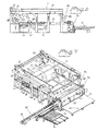
- Figure 1 shows schematically a view in perspective of parts of a reel-up in a paper machine, seen downstream from the operator side, said reel-up having a handling station of which only the lifting device according to the invention is shown.
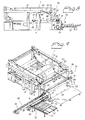
- Figures 2 and 3 show schematically a view from the side and in perspective of the reel-up according to Figure 1 with the handling station drawn in, the reel-up being in its initial operating position.
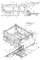
- Figures 4-15 show schematically views of the reel-up according to Figure 1 in different operating positions.
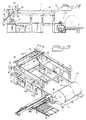
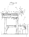
- Figures 16 and 17 show schematically parts of the reel-up and its handling station at the downstream end.
-
- Figure 1 shows schematically in perspective parts of a reel-
up 1 in a paper machine in which paper is manufactured in acontinuous web 2 which is reeled onto arotatable reeling drum 4 in the reel-up 1 to form a reel ofpaper 3. The reel-up 1 comprises astand 5 with first and second longitudinally extending,parallel stand parts horizontal rails 8 rigidly mounted above eachstand part surface winding drum 9 is rotatably journalled at thestand parts up 1. A drive means (not shown) gives the surface winding drum 9 a peripheral speed corresponding to the speed of thepaper web 2. Thestand rails 8 are arranged at a distance from each other which is somewhat greater than the breadth of thepaper web 2. The reelingdrum 4 is provided at each end with abraking drum 10 comprising acoupling member 11 and a bearinghousing 12 situated inside thecoupling member 11, provided with aperipheral groove 13. The reelingdrum 4 rolls along thestand parts peripheral grooves 13 cooperating with thestand rails 8. In the embodiment shown each reelingdrum 4 is provided with two form-stablecylindrical cores 14. Alternatively only one core may be used, as shown in Figure 1. Thereeling drum 4 has expandable plates which in active state, i.e. expanded, lock thecores 14 to the reeling drum and which in inactive state, i.e. unexpanded, release the core from the reeling drum. - The reel-up stand is provided with a horizontal, frame-like
top stand part 16 supported by a plurality ofpillars 17 and comprising twoparallel beams 18 extending in machine direction. Asupport element 19 is arranged on the inside of eachbeam 18 and rigidly joined to this bycrossbars 20. Thesupport elements 19 are spaced from thebeam 18 and provided withrails 21 situated at a higher level than thebeams 18. Therails 21 are arranged to carry reelingdrums 4 provided with cores, these drums forming astock 15 for the continuous operation of the reel-up. Like thelower rails 8, theupper rails 21 are dimensioned to fit with clearance into theperipheral grooves 13 of thereeling drums 4. Theupper rails 21 andlower rails 8 are situated in pairs in a common vertical plane. The reel-up is provided with afeeding device 22 for feeding a reelingdrum 4 along therails 21 when the reeling drum has been lifted and placed on therails 21. Thefeeding device 22 comprises afeeder 23 arranged close to eachrail 21 to be brought into abutment with a reeling drum when it is to be fed forward. The feeding device also comprises apneumatic actuator 24 arranged on the outer side of eachsupport element 19 to move thefeeder 23 to and fro along therail 21. It will be understood that the twoactuators 24 are synchronised with each other. In the embodiment shown theactuator 24 consists of acylinder 28 and a piston (not shown) movable therein, with which thefeeder 23 is connected via a connection piece 25 (see Figure 16), extending through a longitudinally extending, self-sealing groove (not shown) in thecylinder 28. Thefeeder 23 is pivotably arranged to be swung down to an inactive position under the influence of a reelingdrum 4, when thefeeder 23 is returned to fetch this reeling drum. Thefeeder 23 is arranged to be automatically swung up to its active position by means of springs. Counterweights may be used instead of springs. Anend stop 30 is arranged at eachrail 21 to stop the forward feeding when the reelingdrum 4 encounters theend stop 30. Detectors 31 (see Figure 17) are also provided close to these end stops 30, arranged on the inner side of thesupport elements 19, to detect the presence and position of the foremost reelingdrum 4. - At its upstream end the reel-up is provided with a pair of lowering arms 32 (see Figures 14 and 15), which are pivotably mounted on the
pillars 17 located there. With the aid of these lowering arms 32 a reelingdrum 4 is transferred from theexit 29 of thedrum stock 15 down to a primary system for receipt of a reelingdrum 4 which is arranged in connection with thesurface winding drum 9. A pair ofactuators 34 is arranged at the loweringarms 32, extending between each one loweringarm 32 and thestand part arm 32 comprises aroll surface 35 extending along the upper edge of thearm 32 from its free, outer end and being defined by anouter grab hook 36 and an inner drum shock absorber 37 (see Figure 1) Adetector 33 is also arranged at eachdrum shock absorber 37 to detect when the reelingdrum 4 gripped by thegrab hook 36 and lifted by the loweringarm 32 has rolled along theroll surface 35 to the desired position before the loweringarm 32 returns to the primary system for receiving the reelingdrum 4. The receiving primary system (see Figures 2-5) comprises twoprimary arms 38 arranged to receive the new reelingdrum 4 either directly from the loweringarms 32 or from a pair of loweringsurfaces 39 arranged at each end of thesurface winding drum 9 and on a level with its upper side, when thepaper reel 3 growing around the reelingdrum 4 situated downstream approaches a certain predetermined size (see Figure 6). - The reel-
up 1 further comprises a secondary system having a pair of linearly movable secondary carriages 42 (see Figures 6 and 7) which are displaceable by means ofactuators 44 along a track or tracks 45 at each standpart primary arms 38 are arranged to bring the reelingdrum 4 into contact with thesurface winding drum 9 over which thepaper web 2 runs, in order to commence reeling of thepaper web 2. While a number of turns of thepaper web 2 are wound onto the reelingdrum 4, the latter is conveyed by theprimary arms 38, along the periphery of thesurface winding drum 9 down to thestand parts drum 4 during continued reeling. Theactuator 44 for the secondary carriage 42 (see Figure 6) consists of a hydraulic or pneumatic cylinder which is secured by one end to thesecondary carriage 42 and by its other end to thestand secondary carriages 42 along thetracks 45 are thus synchronised with each other and with the increasing diameter of thepaper reel 3 so that thesecondary carriages 42 follow thepaper reel 3 along its horizontal movement during the continued reeling to a finishedjumbo roll 3. - Each primary and secondary system comprises gripping members formed by a
locking device 47 and apress device 48. The gripping members support the reelingdrum 4 while at the same time allowing it to rotate freely inside the gripping members. The gripping members of the secondary system is arranged to receive the reelingdrum 4 from the gripping members of the primary system so that the end parts of the reelingdrum 4 rest with theirbearing housings 12 directly on therails 8. They may alternatively rest on separate rails. Thepress device 48 is arranged to act against the bearinghousing 12 during reeling, so that a desired and adjustable linear pressure is maintained in the nip between thesurface winding drum 9 and the growingpaper reel 3. Acentral drive 100 for the reelingdrum 4 is also arranged at the secondary system (see Figure 1) which means that the reelingdrum 4 can be connected to a separate drive member via theopposite coupling device 11 of the reelingdrum 4. Since this drive member is mounted on one of thesecondary carriages 42, it is linearly displaceable together with these in a direction parallel to therails 8. Abraking station 49 is also arranged at the downstream end of the reel-up 1 (see Figures 8 and 9), at whichbraking station 49 thepaper reel 3 arrives when reeling has been completed and after thepaper web 2 has been cut. In thebraking station 49 thepaper reel 3 is retarded to stand-still by abraking device 50 mounted at each standpart braking device 50 comprises brakingarms 51 with associated actuators and brake linings. The cut end of the web is also taped to the surface of thejumbo roll 3 in thebraking station 49. Thebraking station 49 also comprises anejection device 55 which causes thepaper real 3 to roll towards the downstream end. Astop 56 and ashock absorber 57 are provided at the downstream end of each standpart - Upstream of the
surface winding drum 9 is a cutting device, not shown, which slits thepaper web 2 into twoweb sections cores 14 threaded onto the reelingdrum 4, thus allowing eachweb section own core 14. - The reel-up also comprises a
multi-functional handling station 54 situated at its downstream end for handling finished reels ofpaper 3, reelingdrums 4 andcores 14 therefor. The handlingstation 54 comprises a lifting table 58 (see Figure 7) extending between thestand parts vertical actuators 59 distributed along its long sides. The lifting table 58 is provided on its upper side, in the vicinity of the driving side, with suitable sleeve stops 110. - The handling
station 54 also comprises adevice 60 for axial displacement of a reeling drum 4 (see Figure 11). Thisdrum moving device 60 is situated on the operator side of the reel-up, aligned with said lifting table 58, and comprises a longitudinally extending,horizontal support element 62 arranged at right angles to the machine direction and formed by two parallelU-shaped rails 63, thetop surfaces 64 of which form sliding surfaces for the reeling drums 4. Between them therails 63 define a space for receiving acarriage 67 slidingly journalled on therails 63. Thecarriage 67 supports a grippingmember 66 for detachable connection to the opposing end portion of a reelingdrum 4. Amotor 69 is mounted at the outer end part of thesupport element 62 to drive acogged belt 70 rigidly connected to thecarriage 67 to move the carriage to and fro in thesupport element 62. - The lifting table 58 has concave or arched form (see Figure 13) so that the two
jumbo rolls 61 formed after withdrawal of the reelingdrum 4 are safely retained. The lifting table 58 is also arranged, with the help ofactuators 59, to tip the jumbo rolls 61 in downstream direction either directly to a suitable transport device (not shown), such as a travelling carriage or a conveyor belt, or to a bench 71 (see Figures 7 and 15) from which the jumbo rolls 61 are then transported further, either to a subsequent work station usually including some type of conversion or rewinding station, or to intermediate storage with the aid of an overhead crane or truck, for instance. The cores are then returned from this station to the reel-up. - The handling
station 54 further comprises a core-feeding device 72 (see Figure 9) provided with a horizontal, longitudinally extendingchannel 78 arranged at right angles to the machine direction and situated below thedrum moving device 60. Thechannel 78 is open at its inner end, situated in anopening 111 in thestand part 6. Afeeder 82 is slidably journalled in thechannel 78. Amotor 83 is mounted at the inner end portion of thechannel 78 to drive a cogged belt (not shown) which is rigidly connected to thefeeder 82 in order to move thefeeder 82 to and fro in thechannel 78. The starting position of thefeeder 82 is behind thecore 14 and, when actuated, it will press against the rear end of the core 14 to feed it through theopening 111 in thestand part 6 and out onto the lifting table 58. One side wall of thechannel 78 is provided with aninlet opening 79 which is slightly longer than acore 14. The core-feedingdevice 72 is also provided with a magazine forcores 14 to be used. The magazine includes aramp 73 arranged opposite the inlet opening 79 of thechannel 78 and inclined towards this opening. Theramp 73 is provided withside plates 75 towards which the ends of the cores face and which serve as guides for thecores 14. A stop mechanism 76 (see Figure 8) is arranged at the outlet end of theramp 73 which in closed position retains thecores 14 on theramp 73 and in open position allows thelowermost core 14 to roll down into thechannel 78, after which it returns to closed position. The core-feedingdevice 72 comprises control equipment (not shown) with associated detectors at the inlet and outlet openings for the stored cores. - The handling
station 54 further comprises alifting device 84 to lift a reelingdrum 4 provided with core(s) from the lifting table 58 to thedrum stock 15 at the top of the reel-up (see Figures 8, 9, 16, 17). The liftingdevice 84 comprises two liftingelements 85, in the embodiment shown constituting Z-shaped lifting arms pivotably journalled each in itsown support element 19. Each lifting arm is made in one piece and has an outerlifting arm part 86, an innerlifting arm part 87 and aninner journalling part 88. The two liftingarm parts journalling part 88 together form said Z-shape. The outer andinner arm parts pocket 89 between them for receipt of an end portion of a reelingdrum 4. The innerlifting arm part 87 and thejournalling part 88 form substantially a right angle with each other. An actuator 90 in the form of a power cylinder is joined by one end to theinner journalling part 88 spaced from itsjournalling shaft 112 and with its other end at anattachment element 113 rigidly mounted on the support element 19 (see Figures 8 and 9). The force lines of thepower cylinders 90 are in their extensions situated at a distance from thejournalling shafts 112 of the liftingarms 85 so that the requisite leverage is obtained when activating the liftingarms 85. The free end of the outerlifting arm part 86 is provided with an upwardly directedstop 91, seen in the lower starting position of the lifting arm, to retain a reelingdrum 4 on the outerlifting arm part 86 when lifting is to commence. The liftingarms 85 are joined together by means of aparallel shaft 96, thus ensuring that the liftingarms 85 are turned synchronously. The liftingarms 85 are situated in the machine direction and are parallel with each other. Their outer and innerlifting arm parts drum 4 rolls during commencement and completion of the lift. A shock absorber 92 (see Figure 17) is arranged at the transition between the outer and innerlifting arm parts arms 85 from being damaged as a result of the impact energy of the reelingdrums 4 against the liftingarms 85, whichshock absorber 92 comprises acurved impact absorber 93 and a dampingmember 94 for this in the form of a hydraulic cylinder. A plurality ofdetectors 40, 41 (see Figure 16) are arranged on or close to each liftingarm 85 to detect some of the positions of the reelingdrum 4 in the liftingarm 85 during its rolling movement therein. In the embodiment shown thedetectors 40 are arranged to detect the position of the reeling drum in said V-shaped pocket to obtain a signal for continued lifting of the reelingdrum 4 to the level of therails 21 of thedrum stock 15, i.e. the presence of both ends of the reelingdrum 4 is registered by thedetectors 40. Thedetectors 41 are arranged at the end of theinner journalling part 87 to detect the completion of the lift and subsequent delivery of the reelingdrum 4 to therails 21 of thedrum stock 15 so that the liftingarms 85 can return to their lower fetching positions. Ashock absorber 95 is also arranged at the end of theinner journalling part 87 in order to dampen the rolling-off movement of the reelingdrum 4 from the liftingarms 85 onto therails 21 of thedrum stock 15. Blockingmembers 98 are arranged at suitable points along therails 21, which blockingmembers 98 are arranged to be folded away under the influence of a reelingdrum 4 rolling on the rails and then to return to their blocking position in which the reelingdrum 4 is prevented from rolling backwards. The blocking members may be provided with springs or counterweights. - The handling
station 54 also comprises a control and adjustment unit of any type whatsoever (not shown), to which thedetectors actuators 90 are connected for activation and de-activation of theactuators 90 that operate the lifting arms. Theother detectors - When the reeling process is initiated in the reel-up 1 (see Figure 2), the
primary arms 38 are in their upper, receiving position with their gripping members above thesurface winding drum 9, said gripping member being open and ready to receive a first reelingdrum 4. Thesecondary carriages 42 are in their upstream positions close to thesurface winding drum 9. A first reelingdrum 4 is located on theupper rails 21 above thesurface winding drum 9, ready to be gripped by the loweringarms 32, the latter being still in their lowermost position. Downstream in the reel-up 1 thebraking station 49 is ready with itsbraking arm 51, to receive and retard a finishedjumbo roll 3. The cutting device has been started but is not in production position. Downstream and near the operator side of the reel-up 1 thefirst core 14 waits in its feed-in position in the core-feeding device 72 (see Figure 3). The lifting table 58 is in its lowermost position and thefurthermost core stop 110, in the direction of insertion of the core 14, is set to receive thefirst core 14 in a position on the lifting table 58 suited for the actual dividing of thepaper web 2. A reelingdrum 4, as yet without a core, is in the feed-in position in thedrum moving device 60 at the side of the reel-up. The liftingarms 85 are in their lowermost position. Thefeeder 23 of thefeeding device 22 is in a ready position at theentry end 99 of the drum stock 15 (see Figure 16). - When start has been initiated the lowering
arms 32 move up to thedrum stock 15 and the outermost of the reelingdrums 4 in thedrum stock 15 is lifted over the end stop 30 of thedrum stock 15 by the lowering arms 32 (see Figures 1, 14, 15), after which the reelingdrum 4 will roll along the roll surfaces 35 of the loweringarms 32 to theshock absorbers 37. The detectors 33 (see Figure 1) indicate when the reeling drum has reached the correct position, whereupon the loweringarms 32 are turned down towards the lowering surfaces 39 (see Figure 14) of the primary system, a distance above thesurface winding drum 9, where the gripping devices of theprimary arms 38 take over the reelingdrum 4. During the downward movement the reelingdrum 4 again rolls towards the grab hooks 36 of the loweringarms 32, but the latter have in the meanwhile been lowered sufficiently far to allow the reelingdrum 4 free passage past the end stop 30 of thedrum stock 15 and the next reelingdrum 4 is now fed thus far by the feeding device 22 (see Figure 12). - The
press device 48 and lockingdevice 47 of theprimary arms 38 together encompass the reelingdrum 4 and position it in its starting position. The reelingdrum 4 is then accelerated up to the same peripheral speed as that of thesurface winding drum 9 in order to minimise the friction when these are brought into contact with each other. When contact is made with the paper web 2 a wrapping occurs and thepaper web 2 is transferred in suitable manner to the reelingdrum 4, e.g. thepaper reel 3 growing downstream (see Figure 6) can be retarded so that a surplus appears in theweb 2 which is drawn into the nip and then cut off. Alternatively the wrapping can be effected by glue or tape having been applied on thecores 14 of the reelingdrum 4. If thepaper web 2 is to be divided intoseveral web sections 52, 53 (see Figure 5), the cutter is started. While a number of turns of thepaper web 2 are wound onto the reelingdrum 4, this is moved by theprimary arms 38 along the periphery of thesurface winding drum 9 down to thestand parts 6, 7 (see Figures 4, 5) where the gripping members of the secondary system take over control of the reeling drum 4 (see Figure 6). The loweringarms 32 are thus free to pass the primary lowered reelingdrum 4 to be turned up to thedrum stock 15 ready to fetch the next reelingdrum 4 when a signal therefor is given. - While the
paper reel 3 is growing theprimary arms 38 first and then, after delivery of the reelingdrum 4 to the secondary system, thesecondary carriages 42, are gradually positioned outwardly from thesurface winding drum 9. For the secondary system this means that thesecondary carriages 42 move synchronously horizontally along the stand rails 8 (see Figure 6). - When the
paper reel 3 has reached its full size it rolls forward to thebraking station 49 where it is gripped by the braking arms 51 (see Figure 8). Thereel 3 is now retarded to about 20% of production speed and the central drive is disconnected. The drive is stopped completely and thepaper reel 3 is passed over to thehandling station 54 by the ejection device 55 (see Figure 10) and its arrival is detected by the detectors 43 (see Figure 16). - The lifting table 58 and
paper reel 3 are raised a short way from therails 8 of thestand parts drum 4 is free from thestand 5 and the reelingdrum 4 can be removed (see Figures 10 to 13) by itsbraking drum 10 on theoperator side 6 being gripped by the grippingmembers 66 of thedrum moving device 60. The plates of the reelingdrum 4 are loosened, thus disengaging thecores 14, after which the grippingmember 66 pulls out the reelingdrum 4 to a rest position on the support element 62 (see Figures 11 and 13). The jumbo rolls 61 now released on the lifting table 58 are tipped out onto the bench 71 (see Figure 15) by the inner and outer rows ofactuators 59 of the lifting table 58 (see Figure 7) being activated in opposite directions. A truck or overhead crane, for instance, then collects thepaper reels 61. - A
core 14 is caused to roll from theramp 73 to thechannel 78 situated downstream in rolling-out direction. Thecore 14 is then fed along thechannel 78 with the aid of thefeeder 82 in axial direction to the lifting table 58 (see Figure 5). Thecore stop 110 of the lifting table 58 and its concave shape guarantee that thecores 14 arrive in the correct position on the lifting table 58. When the same number ofcores 14 as there are cutweb sections paper web 2 have thus been inserted axially one after the other on the lifting table 58 (see Figure 5) and the lifting table 58 has been lifted by itsactuators 59 to the level of thedrum moving device 60, the latter's grippingmembers 66 again inserts the reelingdrum 4 through all thecores 14 on the lifting table 58 to a rest position with each end of the reelingdrum 4 on the stand rails 8 (see Figure 7). - The machine operator causes the reeling
drum 4 to expand, thereby firmly locking thecores 14 in the correct position for thecut web sections drum 4 with its cores is then ready to be automatically transported up to therails 21 of thedrum stock 15 by the liftingdevice 84 at the downstream end of the reel-up 1. The liftingarms 85 are thus in their lowermost position, to which they are lowered each time a reelingdrum 4 with its cores has been lifted up. - The
actuators 90 of thelifting device 84 are activated during a short interval so that a first initial upward turning movement is achieved. The reelingdrum 4 is gripped by eachstop 91 on the liftingarms 85 and lifted a short distance so that the reelingdrum 4 will be caused to roll slowly towards thepockets 89 formed between the outer and innerlifting arm parts 86, 87 (see Figures 8 and 9). When the reelingdrum 4 has been gripped, the lifting table 58 is lowered to its lowermost position by the liftingdevice 84. The impact energy of thedrum 4 caused by the rolling is taken up by the shock absorbers 92 (see Figure 17) and when both ends of the reelingdrum 4 have thus arrived in saidpockets 89, thedetectors 40 in the pockets indicate that thedrum 4 is in the correct position for lifting. - The
actuators 90 are once more activated and the reelingdrum 4 lifted up to theentry 99 of thedrum stock 15 where it rolls off the innerlifting arm parts 87 of the liftingarms 85, down onto the rails 21 (see Figures 11 and 17). The rolling movement is somewhat retarded by theshock absorbers 95. Thedetectors 41 indicate that the reelingdrum 4 has been transferred to thestock 15 and the liftingarms 85 are then swung back to their lowermost positions. - The reeling
drum 4 passes the blockingmembers 98 arranged on eachrail 21 which, after having been folded aside during passage of the drum, are turned back to their upright blocking positions thereby preventing the reelingdrum 4 from rolling back. Finally, thefeeders 23 move the reelingdrum 4 forward to theoutlet 29 of thedrum stock 15, either as far as the reelingdrums 4 already there or to the end stop 30 (see Figure 17). Thedetectors 31 indicate in the first case that both ends of the reelingdrum 4 have reached the correct position. - The above-mentioned actuators may be hydraulic, pneumatic, electric or mechanical actuators.
- Some or all of the parts of the handling station situated on the operator side may be placed on the drive side of the reel-up if so desired.
- The reeling station of the reel-up may of course be designed in various known ways. In an alternative embodiment (not shown) the reel-up has no primary system and has instead double secondary units movable linearly along the machine stand, said secondary units alternately with each other receiving the reeling drums directly from said lowering arms. Each second unit then supports the reeling drum throughout the production phase from empty reeling drum to finished paper reel. Alternatively the secondary system may consist of only one pair of pivotable secondary arms.
- Additional detectors to those described may be arranged at suitable points in the reel-up to detect the beginning or end of various phases or movements during reeling of the paper web and handling the reeling drums, cores and paper reels.
Claims (9)
- A reel-up in a paper machine for manufacturing a paper web (2) which is reeled onto reeling drums (4) provided with cores (14) to form reels (3) of paper, said reel-up having an upstream end and a downstream end and comprising:a lower pair of parallel rails (8) extending from said upstream end to said downstream end to support a reeling drum (4), the opposing end portions of which are arranged to roll along the rails (8),an upper pair of parallel rails (21) extending from the downstream end to the vicinity of the upstream end above and spaced from the lower pair of rails (8) to support a stock (15) of reeling drums provided with cores, the opposite end portions of the reeling drums being arranged to roll along the upper rails (21) ,a reeling station arranged immediately downstream of the upstream end in connection with the lower pair of rails (8) for reeling the paper web onto the reeling drum,lowering devices for lowering a reeling drum provided with core(s) from the upper pair of rails (21) to said reeling station,a mufti-functional handling station (54) situated at said downstream end for handling finished reels of paper (3), reeling drums (4) and cores (14), said handling station comprisinga vertically movable lifting table (58) for receipt of each of a finished reel of paper,a device (60) for moving a reeling drum (4) from a reel of paper located on the lifting table (58) and for inserting the reeling drum into one or more cores (14) arranged on the lifting table and aligned with the drum moving device (60) after the reel of paper has been removed from the lifting table, anda device for feeding cores (14) out onto the lifting table (58),said multi-functional handling station (54) being provided with a lifting device (84) having two lifting elements (85) arranged to be brought into engagement with the end portions of a reeling drum (4) provided with core(s) and situated on the lifting table (58), and to lift this and deliver it to the upper pair of rails (21), and actuators (90) connected to the lifting elements (85) to move them from the lifting table (58) to the delivery point for the reeling drum at the upper pair of rails (21), characterized in thatthe lifting elements (85) consist of lifting arms pivotably journalled in the reel-up on stationary journalling shafts allowing rotation from a lower, fetching position to an upper delivery position, andeach of the pivotably mounted lifting arms (85) comprises an outer lifting arm part (86), an inner lifting arm part (87) and an inner journalling part (88), along which lifting arm parts (86, 87) the reeling drum (4) is intended to roll, the journalling part (88) forming an operating arm joined to one end of an actuator (90), the other end of which is mounted on the upper rails (21) or on an attachment element (113) in the vicinity of the upper rails.
- A reel-up as claimed in claim 1, characterized in that the lifting arm (85) is Z-shaped, the outer and inner lifting arm parts (86, 87) forming an acute angle with each other to define a V-shaped pocket (89), and in that the journalling part (88) is arranged substantially at right angle to the inner lifting arm part (87).
- A reel-up as claimed in claim 1 or claim 2, characterized in that the outer lifting arm part (86) of the lifting arm (85) is designed with a stop (91) at its free, outer end in order to ensure that the reeling drum (4) does not roll off the outer lifting arm part (86) at the start of the lift.
- A reel-up as claimed in any one of claims 1-3, characterized in that a first shock absorber (92) is arranged at a transition between the outer and inner lifting arm parts (86, 87), which shock absorber (92) comprises an impact absorber (93) and a damping device (94) arranged at this.
- A reel-up as claimed in claim 4, characterized in that a second shock absorber (95) is arranged at the end portion of the inner lifting arm part (87) situated closest to the journalling part (88) in order to dampen the rolling-off movement of the reeling drum (4) from the lifting arm part (87) out onto the rails (21).
- A reel-up as claimed in any one of claims 1-5, characterized in that a parallel shaft (96) extends between the lifting arms (85), which parallel shaft (96) is arranged to ensure that the lifting arms (85) are operated synchronously with each other.
- A reel-up as claimed in any one of claims 1-6, Characterized in that said handling station (54) comprises a plurality of detecting devices to indicate various positions of the reeling drum (4) for control and adjustment of the movement and stop positions of the lifting elements (85).
- A reel-up as claimed in claim 7, characterized in that said detecting devices comprisefirst detectors (46) arranged to detect the presence of an empty reeling drum (4) provided with core(s), in order to initiate activation of said actuators (90) to bring the lifting elements (85) into engagement with the end portions of the reeling drum,second detectors (40) arranged to detect a predetermined position of the reeling drum on the lifting elements (85) to initiate activation of said actuators (90) to lift and deliver the reeling drum to the upper pair of rails (21), andthird detectors (41) to detect delivery of the raised reeling drum (4) to initiate activation of said actuators (90) to return the lifting elements (85) to inactive position beside the lifting table (58).
- A reel-up as claimed in claim 7 or claim 8, characterized in that the handling station (54) comprises a control and adjustment unit to which the detecting devices (40, 41, 46) and actuators (90) are connected, to activate and de-activate said actuators (90).
Applications Claiming Priority (2)
| Application Number | Priority Date | Filing Date | Title |
|---|---|---|---|
| SE9800838A SE511670C2 (en) | 1998-03-16 | 1998-03-16 | Wheelchair in a paper machine |
| SE9800838 | 1998-03-16 |
Publications (3)
| Publication Number | Publication Date |
|---|---|
| EP0943569A2 EP0943569A2 (en) | 1999-09-22 |
| EP0943569A3 EP0943569A3 (en) | 1999-11-17 |
| EP0943569B1 true EP0943569B1 (en) | 2003-02-19 |
Family
ID=20410542
Family Applications (1)
| Application Number | Title | Priority Date | Filing Date |
|---|---|---|---|
| EP99104106A Expired - Lifetime EP0943569B1 (en) | 1998-03-16 | 1999-03-01 | Reel-up |
Country Status (4)
| Country | Link |
|---|---|
| EP (1) | EP0943569B1 (en) |
| AT (1) | ATE232832T1 (en) |
| DE (1) | DE69905410T2 (en) |
| SE (1) | SE511670C2 (en) |
Cited By (2)
| Publication number | Priority date | Publication date | Assignee | Title |
|---|---|---|---|---|
| CN109051936A (en) * | 2018-08-14 | 2018-12-21 | 珠海市中亚包装设备有限公司 | Tube-conveyer |
| CN116654691A (en) * | 2023-08-02 | 2023-08-29 | 珠海拾比佰新型材料有限公司 | Automatic paper tube loading equipment |
Families Citing this family (20)
| Publication number | Priority date | Publication date | Assignee | Title |
|---|---|---|---|---|
| IT1308270B1 (en) * | 1999-04-12 | 2001-12-10 | Celli Spa | PLANT AND METHOD FOR THE PREPARATION OF SPINDLES AND WRAPPING CORES FOR REWINDING MACHINES OR SIMILAR |
| WO2003010078A1 (en) * | 2001-07-26 | 2003-02-06 | Enviroxi, Sl | Method and device for the automatic removal of coils from a coil-forming machine |
| WO2003010079A1 (en) * | 2001-07-26 | 2003-02-06 | Enviroxi, Sl | Method and device for the automatic removal/insertion of coils in a coil-forming/-transforming machine |
| DE10148913A1 (en) * | 2001-10-04 | 2003-04-10 | Voith Paper Patent Gmbh | Cylinder magazine, for the supply of winding cylinders at a roll winder, has an angled movement path for them to roll down the slope with a controlled applied resistance to reduce their speed of travel |
| ITMI20012274A1 (en) * | 2001-10-29 | 2003-04-29 | Bielloni Castello S P A | AUTOMATIC REWINDING MACHINE PARTICULARLY FOR FLEXIBLE PLASTIC FILM AND RELATED METHOD OF ROLLS PRODUCTION |
| EP1344735B1 (en) * | 2002-03-12 | 2007-08-29 | DOLCI EXTRUSION S.r.l | Winder for film of plastic material |
| US7255301B2 (en) | 2004-03-01 | 2007-08-14 | Andritz Tissue Inc. | Reel spool storage and loading device and method |
| ITFI20070216A1 (en) * | 2007-09-28 | 2009-03-29 | Celli Paper S P A A | "WRAPPING DEVICE WITH LIFTING ARMS FOR WINDING AUCTIONS" |
| FI125392B (en) * | 2008-09-29 | 2015-09-30 | Valmet Technologies Inc | Method and apparatus for lowering and / or raising a rolling shaft |
| IT1398724B1 (en) | 2010-03-16 | 2013-03-18 | Celli Paper S P A A | "MACHINE AND METHOD FOR WINDING COILS OF RIBBED MATERIAL" |
| DE102013216494A1 (en) | 2013-08-20 | 2015-02-26 | Voith Patent Gmbh | Device for transporting hubs |
| ITMI20131576A1 (en) * | 2013-09-25 | 2015-03-26 | Colines Spa | LOADER FOR ANIME AND EXHAUST AUTOMATIC COILS IN A PLASTIC FILM WINDING MACHINE |
| CN103662918B (en) * | 2013-11-16 | 2016-10-12 | 曹新义 | Rewinding machine is with pumping lever apparatus |
| WO2016150946A1 (en) | 2015-03-23 | 2016-09-29 | Roll-O-Matic A/S | A wind-up apparatus for a web material |
| CN107235382A (en) * | 2017-07-26 | 2017-10-10 | 威海科莱默自动化设备有限公司 | A kind of air-expanding shaft connects changing rig and its connects roll-changing method |
| CN107814239B (en) * | 2017-12-01 | 2023-12-01 | 山东电航电力设备科技有限公司 | Winding core replacing device for single-winding amorphous thin belt full-automatic winding machine |
| CN108341291B (en) * | 2018-03-30 | 2024-02-02 | 厦门攸信信息技术有限公司 | Linear type roll paper packaging machine and control method thereof |
| CN110316592B (en) * | 2019-08-01 | 2024-03-29 | 上海自立塑料制品有限公司 | Full-automatic winding device for polyester packing belt |
| CN114476750A (en) * | 2020-10-23 | 2022-05-13 | 中山润晖机械科技有限公司 | Double-component non-woven fabric complete equipment |
| CN114132778B (en) * | 2021-11-30 | 2024-03-26 | 江苏宏瑞达新能源装备有限公司 | Film spreading machine |
Family Cites Families (7)
| Publication number | Priority date | Publication date | Assignee | Title |
|---|---|---|---|---|
| US3131880A (en) * | 1962-06-11 | 1964-05-05 | Murray D J Mfg Co | Web roll winder shaft stripper |
| DE3015547C2 (en) * | 1980-04-23 | 1986-12-11 | J.M. Voith Gmbh, 7920 Heidenheim | Wrapping machine for web-shaped goods |
| DE3040398C2 (en) * | 1980-10-25 | 1984-09-06 | J.M. Voith Gmbh, 7920 Heidenheim | Process for exchanging a finished lap for an empty lap core in a double-roll winder and device for carrying out the process |
| US4682929A (en) * | 1986-02-03 | 1987-07-28 | Hiroshi Kataoka | Device for taking out sheet rolls and mounting sheet roll cores |
| FI75542C (en) * | 1986-02-27 | 1989-09-11 | Ahlstroem Valmet | Apparatus for moving tambour rolls to a roll or paper machine |
| FI73945C (en) * | 1986-04-03 | 1987-12-10 | Tampella Oy Ab | ANORDNING FOER FOERFLYTTNING AV EN UPPRULLNINGSVALS FOER BANFORMIGT MATERIAL FRAON ETT FOERRAOD TILL EN PRIMAERGAFFEL I EN UPPRULLNINGSANORDNING VID EN PAPPERSMASKIN ELLER LIKNANDE. |
| EP0912436A1 (en) * | 1996-06-13 | 1999-05-06 | Beloit Technologies, Inc. | Core-insertion device for a winding machine |
-
1998
- 1998-03-16 SE SE9800838A patent/SE511670C2/en not_active IP Right Cessation
-
1999
- 1999-03-01 DE DE69905410T patent/DE69905410T2/en not_active Expired - Fee Related
- 1999-03-01 AT AT99104106T patent/ATE232832T1/en active
- 1999-03-01 EP EP99104106A patent/EP0943569B1/en not_active Expired - Lifetime
Cited By (3)
| Publication number | Priority date | Publication date | Assignee | Title |
|---|---|---|---|---|
| CN109051936A (en) * | 2018-08-14 | 2018-12-21 | 珠海市中亚包装设备有限公司 | Tube-conveyer |
| CN116654691A (en) * | 2023-08-02 | 2023-08-29 | 珠海拾比佰新型材料有限公司 | Automatic paper tube loading equipment |
| CN116654691B (en) * | 2023-08-02 | 2023-10-13 | 珠海拾比佰新型材料有限公司 | Automatic paper tube loading equipment |
Also Published As
| Publication number | Publication date |
|---|---|
| EP0943569A2 (en) | 1999-09-22 |
| SE9800838D0 (en) | 1998-03-16 |
| ATE232832T1 (en) | 2003-03-15 |
| DE69905410T2 (en) | 2003-08-14 |
| DE69905410D1 (en) | 2003-03-27 |
| SE511670C2 (en) | 1999-11-08 |
| SE9800838L (en) | 1999-09-17 |
| EP0943569A3 (en) | 1999-11-17 |
Similar Documents
| Publication | Publication Date | Title |
|---|---|---|
| US6047916A (en) | Reel-up and multi-functional handling device therefor | |
| EP0943569B1 (en) | Reel-up | |
| US3695539A (en) | Multiple reel unwind stands | |
| US4778122A (en) | Apparatus for transferring reel drums to the winder of a paper or board machine | |
| US4390138A (en) | Reeling apparatus for a web | |
| FI92042B (en) | Hylsmataranordning | |
| CA1297663C (en) | Apparatus for installing a winding sleeve | |
| EP1571109A1 (en) | Reel spool storage and loading device and method | |
| CA1316893C (en) | Constant tension reel with automatic reel bar loader | |
| UA77965C2 (en) | Device for winding and unwinding hot rolled strip billets of hot metal | |
| US5360180A (en) | Roll-support system for paper-winding machine | |
| FI121461B (en) | A method for treating empty winding shafts to be applied to a fiber web winder | |
| AU603660B2 (en) | Device for unwinding a material web from a roll | |
| EP1348658A1 (en) | Web unwinding device for web rolls | |
| US6260788B1 (en) | Reel-up and associated method | |
| US6016987A (en) | Winding device for a material web, especially for a reel slitting device | |
| CA2066342C (en) | Storage system for storing in roll form | |
| JP2001522767A (en) | Rolling device for continuous product sheet to form roll | |
| EP1126936B1 (en) | Device to remove coils of rolled stock from a corresponding coiling machine | |
| EP0254458A2 (en) | Apparatus and method for wrapping rolls of pressure sensitive sheet material | |
| EP1109733B1 (en) | Apparatus for collecting, distributing and storing flexible laminar elements, in particular industrial hides | |
| US5480279A (en) | Gripper for handling and storing products in roll form | |
| US3695538A (en) | Means for unwinding reels of sheet material | |
| EP2511209B1 (en) | Arrangement for handling machine rolls and reeling shafts in connection with production of fiber webs | |
| DE19852978C2 (en) | Druckmaschinen arrangement |
Legal Events
| Date | Code | Title | Description |
|---|---|---|---|
| PUAI | Public reference made under article 153(3) epc to a published international application that has entered the european phase |
Free format text: ORIGINAL CODE: 0009012 |
|
| AK | Designated contracting states |
Kind code of ref document: A2 Designated state(s): AT DE FR IT |
|
| AX | Request for extension of the european patent |
Free format text: AL;LT;LV;MK;RO;SI |
|
| PUAL | Search report despatched |
Free format text: ORIGINAL CODE: 0009013 |
|
| AK | Designated contracting states |
Kind code of ref document: A3 Designated state(s): AT BE CH CY DE DK ES FI FR GB GR IE IT LI LU MC NL PT SE |
|
| AX | Request for extension of the european patent |
Free format text: AL;LT;LV;MK;RO;SI |
|
| 17P | Request for examination filed |
Effective date: 20000125 |
|
| AKX | Designation fees paid |
Free format text: AT DE FR IT |
|
| RAP1 | Party data changed (applicant data changed or rights of an application transferred) |
Owner name: METSO PAPER KARLSTAD AKTIEBOLAG |
|
| 17Q | First examination report despatched |
Effective date: 20011205 |
|
| GRAH | Despatch of communication of intention to grant a patent |
Free format text: ORIGINAL CODE: EPIDOS IGRA |
|
| GRAH | Despatch of communication of intention to grant a patent |
Free format text: ORIGINAL CODE: EPIDOS IGRA |
|
| GRAA | (expected) grant |
Free format text: ORIGINAL CODE: 0009210 |
|
| AK | Designated contracting states |
Designated state(s): AT DE FR IT |
|
| REF | Corresponds to: |
Ref document number: 69905410 Country of ref document: DE Date of ref document: 20030327 Kind code of ref document: P |
|
| ET | Fr: translation filed | ||
| PLBE | No opposition filed within time limit |
Free format text: ORIGINAL CODE: 0009261 |
|
| STAA | Information on the status of an ep patent application or granted ep patent |
Free format text: STATUS: NO OPPOSITION FILED WITHIN TIME LIMIT |
|
| 26N | No opposition filed |
Effective date: 20031120 |
|
| PGFP | Annual fee paid to national office [announced via postgrant information from national office to epo] |
Ref country code: DE Payment date: 20090320 Year of fee payment: 11 |
|
| PGFP | Annual fee paid to national office [announced via postgrant information from national office to epo] |
Ref country code: FR Payment date: 20090312 Year of fee payment: 11 |
|
| REG | Reference to a national code |
Ref country code: FR Ref legal event code: ST Effective date: 20101130 |
|
| PG25 | Lapsed in a contracting state [announced via postgrant information from national office to epo] |
Ref country code: FR Free format text: LAPSE BECAUSE OF NON-PAYMENT OF DUE FEES Effective date: 20100331 |
|
| PG25 | Lapsed in a contracting state [announced via postgrant information from national office to epo] |
Ref country code: DE Free format text: LAPSE BECAUSE OF NON-PAYMENT OF DUE FEES Effective date: 20101001 |
|
| PGFP | Annual fee paid to national office [announced via postgrant information from national office to epo] |
Ref country code: IT Payment date: 20120330 Year of fee payment: 14 |
|
| PGFP | Annual fee paid to national office [announced via postgrant information from national office to epo] |
Ref country code: AT Payment date: 20120313 Year of fee payment: 14 |
|
| REG | Reference to a national code |
Ref country code: AT Ref legal event code: MM01 Ref document number: 232832 Country of ref document: AT Kind code of ref document: T Effective date: 20130301 |
|
| PG25 | Lapsed in a contracting state [announced via postgrant information from national office to epo] |
Ref country code: AT Free format text: LAPSE BECAUSE OF NON-PAYMENT OF DUE FEES Effective date: 20130301 |
|
| PG25 | Lapsed in a contracting state [announced via postgrant information from national office to epo] |
Ref country code: IT Free format text: LAPSE BECAUSE OF NON-PAYMENT OF DUE FEES Effective date: 20130301 |