EP2015609B1 - Heizkörper für Heizgerät, Herstellungsverfahren des Heizkörpers und Heizgerät für Räume, das mit einem solchen Heizkörper ausgestattet ist - Google Patents
Heizkörper für Heizgerät, Herstellungsverfahren des Heizkörpers und Heizgerät für Räume, das mit einem solchen Heizkörper ausgestattet ist Download PDFInfo
- Publication number
- EP2015609B1 EP2015609B1 EP08290687.6A EP08290687A EP2015609B1 EP 2015609 B1 EP2015609 B1 EP 2015609B1 EP 08290687 A EP08290687 A EP 08290687A EP 2015609 B1 EP2015609 B1 EP 2015609B1
- Authority
- EP
- European Patent Office
- Prior art keywords
- diffuser
- heating
- resistance
- heating element
- electric
- Prior art date
- Legal status (The legal status is an assumption and is not a legal conclusion. Google has not performed a legal analysis and makes no representation as to the accuracy of the status listed.)
- Not-in-force
Links
Images


Classifications
-
- F—MECHANICAL ENGINEERING; LIGHTING; HEATING; WEAPONS; BLASTING
- F24—HEATING; RANGES; VENTILATING
- F24D—DOMESTIC- OR SPACE-HEATING SYSTEMS, e.g. CENTRAL HEATING SYSTEMS; DOMESTIC HOT-WATER SUPPLY SYSTEMS; ELEMENTS OR COMPONENTS THEREFOR
- F24D13/00—Electric heating systems
- F24D13/02—Electric heating systems solely using resistance heating, e.g. underfloor heating
- F24D13/022—Electric heating systems solely using resistance heating, e.g. underfloor heating resistances incorporated in construction elements
-
- B—PERFORMING OPERATIONS; TRANSPORTING
- B23—MACHINE TOOLS; METAL-WORKING NOT OTHERWISE PROVIDED FOR
- B23K—SOLDERING OR UNSOLDERING; WELDING; CLADDING OR PLATING BY SOLDERING OR WELDING; CUTTING BY APPLYING HEAT LOCALLY, e.g. FLAME CUTTING; WORKING BY LASER BEAM
- B23K11/00—Resistance welding; Severing by resistance heating
- B23K11/14—Projection welding
-
- B—PERFORMING OPERATIONS; TRANSPORTING
- B23—MACHINE TOOLS; METAL-WORKING NOT OTHERWISE PROVIDED FOR
- B23K—SOLDERING OR UNSOLDERING; WELDING; CLADDING OR PLATING BY SOLDERING OR WELDING; CUTTING BY APPLYING HEAT LOCALLY, e.g. FLAME CUTTING; WORKING BY LASER BEAM
- B23K11/00—Resistance welding; Severing by resistance heating
- B23K11/16—Resistance welding; Severing by resistance heating taking account of the properties of the material to be welded
- B23K11/20—Resistance welding; Severing by resistance heating taking account of the properties of the material to be welded of different metals
-
- H—ELECTRICITY
- H05—ELECTRIC TECHNIQUES NOT OTHERWISE PROVIDED FOR
- H05B—ELECTRIC HEATING; ELECTRIC LIGHT SOURCES NOT OTHERWISE PROVIDED FOR; CIRCUIT ARRANGEMENTS FOR ELECTRIC LIGHT SOURCES, IN GENERAL
- H05B3/00—Ohmic-resistance heating
- H05B3/40—Heating elements having the shape of rods or tubes
- H05B3/42—Heating elements having the shape of rods or tubes non-flexible
- H05B3/48—Heating elements having the shape of rods or tubes non-flexible heating conductor embedded in insulating material
- H05B3/50—Heating elements having the shape of rods or tubes non-flexible heating conductor embedded in insulating material heating conductor arranged in metal tubes, the radiating surface having heat-conducting fins
-
- B—PERFORMING OPERATIONS; TRANSPORTING
- B23—MACHINE TOOLS; METAL-WORKING NOT OTHERWISE PROVIDED FOR
- B23K—SOLDERING OR UNSOLDERING; WELDING; CLADDING OR PLATING BY SOLDERING OR WELDING; CUTTING BY APPLYING HEAT LOCALLY, e.g. FLAME CUTTING; WORKING BY LASER BEAM
- B23K2103/00—Materials to be soldered, welded or cut
- B23K2103/18—Dissimilar materials
- B23K2103/20—Ferrous alloys and aluminium or alloys thereof
-
- Y—GENERAL TAGGING OF NEW TECHNOLOGICAL DEVELOPMENTS; GENERAL TAGGING OF CROSS-SECTIONAL TECHNOLOGIES SPANNING OVER SEVERAL SECTIONS OF THE IPC; TECHNICAL SUBJECTS COVERED BY FORMER USPC CROSS-REFERENCE ART COLLECTIONS [XRACs] AND DIGESTS
- Y02—TECHNOLOGIES OR APPLICATIONS FOR MITIGATION OR ADAPTATION AGAINST CLIMATE CHANGE
- Y02B—CLIMATE CHANGE MITIGATION TECHNOLOGIES RELATED TO BUILDINGS, e.g. HOUSING, HOUSE APPLIANCES OR RELATED END-USER APPLICATIONS
- Y02B30/00—Energy efficient heating, ventilation or air conditioning [HVAC]
Definitions
- the present invention relates to the field of electric space heating appliances, and more particularly the apparatus with heating bodies including an electrical resistance.
- heating is provided by a heating body formed of one or more electrical resistance (s) associated with one or more incorporated diffuser (s) (s) in a generally metallic envelope, and disposed near the inner end wall of said envelope.
- electrical resistance s
- diffuser s
- thermal diffusers Most of the current heating elements are made using extruded aluminum profiles as thermal diffusers. These profiles incorporate, in longitudinal housing of tubular form, electric heating resistors arranged along the longitudinal axis of these housings and consisting of a wound wire, embedded in compacted grains of magnesia. Magnesia, thermal conductor and good dielectric insulator, thus safely ensures the transfer of heat from the wire to the diffuser.
- Other heaters use as a diffuser mica plates, a silicate-based material. Two plates of mica are glued to each other and sandwich a heating electric resistance consisting of a metal sheet connected to the power supply.
- FR 2,931,427 heating bodies for electric radiators, formed of an assembly of tubular electrical resistances housed in grooves of a diffuser plate, and welded to the latter by adding material, for example a copper wire or a copper tab; .
- the present invention therefore aims to provide a new type of heater for simplified structure heaters and low cost manufacturing, without reducing thermal performance.
- the present invention proposes a heater for an electric space heater, of the type comprising at least one electric heating element constituted by a metallic sheath, incorporating a wound wire, embedded in a dielectric insulator, the resistance electrical connection being fixed by welding of the metal sheath to the surface of at least one of the faces of a metal diffuser substantially in the form of a plate, characterized in that the diffuser and the sheath of the heating resistor are in steel and are welded to one another by mutual fusion of the metals constituting them at the weld zone, without adding additional metal, the surface of the diffuser having, before welding, bosses, the sheath of the electrical resistance being welded to the diffuser exclusively at said bosses.
- the diffuser can therefore be very simple form, since it can be in the form of a single plate.
- the electrical resistance does not have to adapt to a particular configuration of a housing or vice versa, it is not necessary to provide a housing for the resistance within the diffuser.
- This resistance can therefore be of any shape.
- the electrical resistance is therefore attached to the outside of the diffuser and not incorporated inside the latter.
- the heating system is considerably simplified since it consists essentially of fixing by welding without adding additional metal, the electrical resistance to an outer face of the diffuser.
- the electrical resistance consists of a steel sheath, generally tubular in which is incorporated a coiled wire embedded for example in compacted grains of magnesia.
- the welding is carried out at high temperature, by mutual fusion of the metals constituting the diffuser and the sheath of the resistance. electric, at the level of the weld zone.
- the bosses are present on the surface of the diffuser and not, as mentioned in the patent US 3,193,659 on the tubular element to be welded, which, moreover, does not correspond, in this document, to a sheath of electrical resistance.
- the heating body comprises a single electric heating resistor in order to limit the number of connections to the power supply.
- said electric heating resistance it can then be formed of a single straight section, or of several straight sections connected by at least one curved section. The resistance thus winds in direct contact with the surface of at least one side face of the diffuser, so as to transmit and distribute, by conduction, its calories to the entire diffuser.
- the diffuser may be a metal plate of generally flat shape. It may also be a corrugated metal plate having corrugations substantially perpendicular to the (s) straight section (s) of the electrical resistance.
- the corrugations are located between the welding zones. These corrugations serve as "bellows" of expansion of the plate between the weld zones of the sheath of the electrical resistance.
- the protruding regions (bulges) vis-à-vis the electrical resistance may constitute solder areas (corresponding to the aforementioned bosses), the recessed regions away from the electrical resistance serving as zones of possible dilatations.
- possible corrugations parallel to the rectilinear sections of the resistor may constitute partial housings for these said sections in order to increase the peripheral contact of the resistor with the surface of the diffuser, and possibly to increase the possible welding area.
- the diffuser is provided with at least one outer housing that at least partially matches the shape of the electric heating element, so as to promote heat transfer.
- the metal plate constituting the diffuser may be of reduced thickness, preferably between 0.5 mm and 1 mm, allowing the realization of a relatively economical heating body.
- the sheath of the electrical resistance comes into linear contact with the surface of the corresponding face of the diffuser.
- the bosses are limited deformations of the diffuser made for example by means of a stamping tool. These bosses are preferably of oblong shape oriented perpendicularly to the axis of the corresponding section of the electrical resistance (allowing a positioning tolerance of the latter) and preferably have a rounded upper surface. This rounded surface minimizes the contact area between the sheath of the electrical resistance and the boss itself, so as to "focus" the passage of the welding current in this area.
- Such a method makes it possible in particular, with electrodes of greater length, to simultaneously produce several welds at a plurality of bosses, and thus to reduce the manufacturing cycles of the heating body.
- the present invention also relates to an electric space heating appliance, characterized in that it comprises a casing (or casing) incorporating a heating body according to the invention, the diffuser being disposed close to the internal front wall of said casing. and the face of the diffuser opposite to that receiving the electrical resistance by welding being oriented towards said front wall of the envelope.
- This heater may be a convector, a radiant panel, a radiator or a towel warmer.
- the face of the diffuser facing the front wall of the casing is covered with a coating, paint type, increasing the emissivity of the radiation surface of said diffuser.
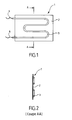
- the heating body 1 according to the invention shown in the figure 1 consists of a heating resistor 3 welded to the diffuser 2 in the form of a flat plate.
- the heating resistor 3 comprises rectilinear sections connected by curved sections. Such a shape makes it possible to implement a single heating resistor 3, with only two connections to the power supply, at each of its ends.
- heating body consisting of extruded aluminum profiles
- a heating body provided with several heating electric resistances, arranged advantageously parallel to each other. In this case, it is necessary to provide connections 6 to the power supply for each heating resistor.
- the figure 2 shows that the electric heating resistance 3 is pressed against the surface of the diffuser 2, as visible on the Figures 3 and 4 ; the fixing of the heating resistor 3 can take place on a diffuser 2 plane ( figure 3 ), or on a diffuser 2 provided with a housing which matches a portion of the outer shape of the cylindrical heating electric heater 3 (cf. figure 4 ).
- the electric heating resistor 3 is here composed of an electric filament 4 mounted in a cylindrical tubular sheath 5 and surrounded by a dielectric insulating material (magnesia) disposed between the electric filament 4 and the sheath 5.
- a dielectric insulating material magnesia
- the heating resistor 3 is here fixed to the surface of the diffuser 2 by means of welds, made by mutual melting of the metals (and not by addition of additional metal) constituting the diffuser 2 and the sheath 5 of the heating resistor, the welding zones. 7 being arranged according to one of the generatrices of the resistance, and spaced apart from each other.
- the diffuser 2 may be in the form of a corrugated plate having corrugations approximately perpendicular to the median axis of the rectilinear sections of the heating resistor 3, as shown in the sectional view of the FIG. figure 5 .
- the welding zones 7 are then formed at the level of bulges of the undulations closest to the resistance. Between these welding zones 7 can thus take place an expansion of the metal of the diffuser, without damaging the quality of the welds.
- These corrugations can be very thin, with a spacing of the order of a millimeter, for example.
- the figure 6 shows the disposition of a heating body 1 within the casing 8 forming the whole of the heating apparatus.
- the diffuser 2 is disposed near the internal front wall 10 of the casing 8, in its lower part.
- the heating resistor 3 is welded to the rear face of the diffuser 2, oriented towards the rear wall 11 of the casing 8.
- the height of the diffuser plate is 245 mm for a length of 460 mm.
- the electrical resistor has three elbows, defining four single parallel straight segments spaced about 70 mm apart.
- the arrangement of the electrical resistance 3 thus bent, further facilitates the connection to the power supply, the connections 6 being on the same side of the heating body 1 (see left side on the figure 1 ).
- thermo conductivity 237 W / mK thermo conductivity 237 W / mK
- the diffuser of substantially flat shape comprises series of bosses 20 made by point stampings of the plate forming the diffuser. These bosses are spaced every 20 to 60 mm approximately.
- the sheath of the electrical resistance 3 is in contact with the diffuser 2 only at the bosses 20.
- the electrodes 21 and 22 located on either side of the diffuser / electrical resistance assembly allow the passage of the current only at the contact areas between the sheath and the diffuser 2, that is to say exclusively at the bosses 20 thus creating precise and localized welding areas.
- bosses 20 are crushed during the approach of the two electrodes 21 and 22 of each other according to the arrows F1 and F2. These flattening of the bosses allow the sheath 5 of the resistor 3 to be, after soldering, in linear contact with the flat surface of the diffuser 2 (see FIGS. Figures 10A and 10B ).
Landscapes
- Engineering & Computer Science (AREA)
- Mechanical Engineering (AREA)
- Physics & Mathematics (AREA)
- Thermal Sciences (AREA)
- Chemical & Material Sciences (AREA)
- Combustion & Propulsion (AREA)
- General Engineering & Computer Science (AREA)
- Resistance Heating (AREA)
- Surface Heating Bodies (AREA)
- Central Heating Systems (AREA)
Claims (12)
- Heizkörper (1) für ein elektrisches Heizgerät für Räume der Bauart, die mindestens einen elektrischen Heizwiderstand (3) aufweist, der von einer metallischen Hülle (5) gebildet wird, die einen gewickelten Metalldraht (4) einschließt, der in einen dielektrischen Isolator (9) eingelassen ist, wobei der elektrische Widerstand durch Schweißen auf der metallischen Hülle (5) auf der Oberfläche mindestens einer der Flächen eines metallischen Diffusors (2) befestigt ist, die sich etwa in Form einer Platte darstellt, dadurch gekennzeichnet, dass der Diffusor und die Hülle des Heizwiderstands aus Stahl sind und durch gegenseitiges Verschmelzen der Metalle, die sie bilden, in der Schmelzzone (7) ohne Hinzufügen von zusätzlichem Metall aufeinander verschweißt sind, wobei die Oberfläche des Diffusors vor dem Schweißen Wülste (20) aufweist, wobei die Hülle des elektrischen Widerstands (3) auf dem Diffusor (2) ausschließlich im Bereich der Wülste (20) verschweißt ist.
- Heizkörper (1) nach Anspruch 1, dadurch gekennzeichnet, dass er einen einzigen elektrischen Heizwiderstand (3) aufweist.
- Heizkörper nach Anspruch 1 oder 2, dadurch gekennzeichnet, dass der elektrische Heizwiderstand (3) von einem einzigen geraden Abschnitt oder von mehreren geraden Abschnitten gebildet wird, die durch mindestens einen gekrümmten Abschnitt verbunden sind.
- Heizkörper nach einem der vorangehenden Ansprüche, dadurch gekennzeichnet, dass der Diffusor (2) eine allgemein ebene Metallplatte ist.
- Heizkörper nach Anspruch 3, dadurch gekennzeichnet, dass der Diffusor (2) eine gewellte Metallplatte ist, die zu dem/den geraden Abschnitt/en des elektrischen Widerstands etwa lotrechte Wellen (12) aufweist.
- Heizkörper nach Anspruch 5, dadurch gekennzeichnet, dass sich die Wellen (12) zwischen den Schweißzonen (7) befinden.
- Heizkörper nach einem der vorangehenden Ansprüche, dadurch gekennzeichnet, dass der Diffusor (2) mit mindestens einer externen Aufnahme ausgestattet ist, die mindestens teilweise die Form des elektrischen Heizwiderstands (3) annimmt.
- Herstellungsverfahren eines Heizkörpers (1) für ein elektrisches Heizgerät für Räume nach einem der vorangehenden Ansprüche durch Verschweißen eines elektrischen Heizwiderstands (3) auf einem Diffusor (2), dadurch gekennzeichnet, dass es die folgenden aufeinanderfolgenden Schritte umfasst:- Herstellen von Wülsten (20) auf der Oberfläche mindestens einer Fläche des Diffusors (2),- Platzieren des elektrischen Heizwiderstands(3) im Kontakt mit dem Diffusor ausschließlich im Bereich der Wülste (20),- Positionieren von mindestens einem Paar Schweißelektroden (21, 22) auf der einen und der anderen Seite der Gruppe, die von dem Diffusor und dem elektrischen Heizwiderstand gebildet wird,- Anlegen einer elektrischen Spannung zwischen den zwei Elektroden (21, 22) und Ausüben eines Drucks in Richtung einer Annäherung der Elektroden, wobei es bei der gegenseitigen Verschmelzung der Metalle, die den Diffusor (2) und die Hülle (5) des elektrischen Widerstands (3) bilden, zu einem Zusammendrücken der Wülste (20) kommt.
- Elektrisches Heizgerät für Räume, dadurch gekennzeichnet, dass es einen Mantel (8) umfasst, der einen Heizkörper (1) nach einem der Ansprüche 1 bis 8 einschließt.
- Elektrisches Heizgerät für Räume nach Anspruch 9, dadurch gekennzeichnet, dass der Diffusor (2) des Heizkörpers (1) in der Nähe der inneren vorderen Wand (10) des Mantels angeordnet ist und die Fläche des Diffusors (2), die dieser gegenüberliegt, auf dem der elektrische Widerstand (3) verschweißt ist, in Richtung der vorderen Wand (10) des Mantels (8) zeigt.
- Heizgerät nach Anspruch 10, dadurch gekennzeichnet, dass er eine strahlende Platte bildet, wobei die Fläche des Diffusors (2), die zur vorderen Wand (10) des Mantels zeigt, mit einem Überzug vom Typ Anstrich bedeckt ist, der der Emissionsvermögen der strahlenden Oberfläche des Diffusors (2) erhöht.
- Heizgerät nach den Ansprüchen 9 oder 10, dadurch gekennzeichnet, dass das Gerät ein Konvektor, eine strahlende Platte, ein Radiator oder ein Handtuchtrockner ist.
Priority Applications (1)
| Application Number | Priority Date | Filing Date | Title |
|---|---|---|---|
| PL08290687T PL2015609T3 (pl) | 2007-07-12 | 2008-07-11 | Korpus grzejny do urządzenia grzewczego, sposób wytwarzania korpusu grzejnego oraz urządzenie grzewcze do pomieszczeń, zawierające taki korpus grzejny |
Applications Claiming Priority (1)
| Application Number | Priority Date | Filing Date | Title |
|---|---|---|---|
| FR0705072A FR2918836B1 (fr) | 2007-07-12 | 2007-07-12 | Corps de chauffe pour appareil de chauffage,et appareil de chauffage de locaux incorporant un tel corps de chauffe |
Publications (3)
| Publication Number | Publication Date |
|---|---|
| EP2015609A2 EP2015609A2 (de) | 2009-01-14 |
| EP2015609A3 EP2015609A3 (de) | 2009-11-04 |
| EP2015609B1 true EP2015609B1 (de) | 2014-11-19 |
Family
ID=38880991
Family Applications (1)
| Application Number | Title | Priority Date | Filing Date |
|---|---|---|---|
| EP08290687.6A Not-in-force EP2015609B1 (de) | 2007-07-12 | 2008-07-11 | Heizkörper für Heizgerät, Herstellungsverfahren des Heizkörpers und Heizgerät für Räume, das mit einem solchen Heizkörper ausgestattet ist |
Country Status (4)
| Country | Link |
|---|---|
| EP (1) | EP2015609B1 (de) |
| ES (1) | ES2530668T3 (de) |
| FR (1) | FR2918836B1 (de) |
| PL (1) | PL2015609T3 (de) |
Families Citing this family (1)
| Publication number | Priority date | Publication date | Assignee | Title |
|---|---|---|---|---|
| CN101749859B (zh) * | 2010-02-11 | 2012-02-29 | 季连祥 | 卧式幅板竖置式热风炉 |
Family Cites Families (11)
| Publication number | Priority date | Publication date | Assignee | Title |
|---|---|---|---|---|
| US3117249A (en) * | 1960-02-16 | 1964-01-07 | Sperry Rand Corp | Embedded heater cathode |
| US3193659A (en) | 1962-03-26 | 1965-07-06 | Whirlpool Co | D-section tubing with welding projections thereon and method of forming the same |
| FR1465590A (fr) * | 1965-11-30 | 1967-01-13 | Vulcain | Plaques chauffantes |
| FR2301780A1 (fr) * | 1975-02-21 | 1976-09-17 | Sepro | Convecteur electrique |
| EP0102927B1 (de) * | 1982-09-03 | 1986-07-30 | Elpatronic Ag | Buckelanordnung zum Mehrfachbuckelschweissen und ein Verfahren zum Mehrfachbuckelschweissen |
| FI81473C (fi) * | 1988-05-16 | 1990-10-10 | Loval Oy | Uppvaermningselement foer elektriska rumsuppvaermare, speciellt av genomstroemningstyp. |
| FR2632660B1 (fr) * | 1988-06-08 | 1990-09-21 | Seb Sa | Procede pour fixer un tube metallique sur une surface metallique et dispositif ainsi obtenu |
| DE3938895A1 (de) * | 1989-04-13 | 1991-05-29 | Karl Jacobi | Graugusselektroheizplatte als heizkoerper (stationaer und portabel) zur allgemeinen beheizung |
| FR2730120B1 (fr) * | 1995-02-01 | 1997-03-28 | Seb Sa | Element chauffant avec plaque diffusante |
| FR2733383B1 (fr) * | 1995-04-19 | 1997-06-06 | Seb Sa | Element chauffant brase sur support |
| FR2931427A1 (fr) | 2008-05-26 | 2009-11-27 | Peugeot Citroen Automobiles Sa | Procede de decouplage d'une machine electrique de traction sur un vehicule hybride et vehicule hybride pour la mise en oeuvre du procede |
-
2007
- 2007-07-12 FR FR0705072A patent/FR2918836B1/fr not_active Expired - Fee Related
-
2008
- 2008-07-11 ES ES08290687T patent/ES2530668T3/es active Active
- 2008-07-11 EP EP08290687.6A patent/EP2015609B1/de not_active Not-in-force
- 2008-07-11 PL PL08290687T patent/PL2015609T3/pl unknown
Also Published As
| Publication number | Publication date |
|---|---|
| EP2015609A2 (de) | 2009-01-14 |
| PL2015609T3 (pl) | 2015-05-29 |
| FR2918836B1 (fr) | 2011-01-14 |
| EP2015609A3 (de) | 2009-11-04 |
| FR2918836A1 (fr) | 2009-01-16 |
| ES2530668T3 (es) | 2015-03-04 |
Similar Documents
| Publication | Publication Date | Title |
|---|---|---|
| EP1145842B1 (de) | Verbundglasscheibe | |
| EP2185046B1 (de) | Heisswasserbereiter für eine getränkezubereitungsmaschine | |
| EP2804516B1 (de) | Handtuchtrocknungsstrahler mit mindestens einer handtuchstange mit eingebautem kühlkörper mit einem elektrischen heizkabel | |
| EP0680585B1 (de) | Elektrischer kessel für wärmeträgerflüssigkeit in einem offenen oder geschlossenen kreislauf | |
| FR2654978A1 (fr) | Piece de raccordement du type a resistance electrique perfectionnee pour la reunion par thermosoudage d'elements en matiere plastique. | |
| EP0017084A1 (de) | Thermoelektrische Vorrichtung zum Wärmeaustausch mit Flüssigkeitsleitung | |
| EP2015609B1 (de) | Heizkörper für Heizgerät, Herstellungsverfahren des Heizkörpers und Heizgerät für Räume, das mit einem solchen Heizkörper ausgestattet ist | |
| EP2251611A1 (de) | Modulelement für Heizgerät mit Wärmeübertragungsflüssigkeit, und elektrisches Heizgerät, das aus mindestens einem solchen Element besteht | |
| WO2018202961A1 (fr) | Module chauffant pour appareil de chauffage électrique | |
| EP2251612A1 (de) | Elektrisches Heizgerät mit Wärmeübertragungsflüssigkeit, das aus gegossenen Modulelementen besteht | |
| FR2925374A1 (fr) | Procede de soudure d'elements tubulaires pour radiateur a fluide caloporteur et radiateur ainsi realise | |
| EP2400236A1 (de) | Modul eines elektrischen Heizgeräts mit Abdeckung und Wärmeübertragungsflüssigkeit | |
| WO2012001294A1 (fr) | Canne chauffante comprenant une enveloppe dans laquelle au moins une résistance électrique chauffante est montée | |
| EP2109344A2 (de) | Heizkörper eines Elektroradiators, der einen Metallheizfaden in spiralförmiger Aufwicklung mit differenzierten Spiralzonen umfasst | |
| FR2631427A1 (fr) | Element chauffant pour un radiateur electrique utilise pour le chauffage de locaux, notamment de type continu | |
| FR3027736A1 (fr) | Module thermoelectrique a realisation simplifiee et procede de realisation d'un tel module thermoelectrique | |
| EP4600561A1 (de) | Flüssigkeitsheizkörper mit externem heizkörper | |
| FR3156629A3 (fr) | Resistance electrique chauffante emettant dans un demi espace . | |
| EP0563955B1 (de) | Verfahren zur Herstellung eines Durchlauferhitzers für Ausgabevorrichtung für warme Getränke | |
| FR2463372A1 (fr) | Dispositif thermoelectrique a transfert de chaleur entre un premier fluide liquide et un deuxieme fluide | |
| FR2866102A1 (fr) | Radiateur muni de plaques rayonnantes et procede de fabrication de ce radiateur | |
| FR2725105A1 (fr) | Element chauffant | |
| FR2690807A1 (fr) | Dispositif de chauffage, notamment sèche-serviette, à cordon électrique chauffant. | |
| FR2958827A1 (fr) | Corps de chauffe electrique | |
| FR3097953A1 (fr) | Dispositif chauffant pour véhicule automobile. |
Legal Events
| Date | Code | Title | Description |
|---|---|---|---|
| PUAI | Public reference made under article 153(3) epc to a published international application that has entered the european phase |
Free format text: ORIGINAL CODE: 0009012 |
|
| AK | Designated contracting states |
Kind code of ref document: A2 Designated state(s): AT BE BG CH CY CZ DE DK EE ES FI FR GB GR HR HU IE IS IT LI LT LU LV MC MT NL NO PL PT RO SE SI SK TR |
|
| AX | Request for extension of the european patent |
Extension state: AL BA MK RS |
|
| PUAL | Search report despatched |
Free format text: ORIGINAL CODE: 0009013 |
|
| AK | Designated contracting states |
Kind code of ref document: A3 Designated state(s): AT BE BG CH CY CZ DE DK EE ES FI FR GB GR HR HU IE IS IT LI LT LU LV MC MT NL NO PL PT RO SE SI SK TR |
|
| AX | Request for extension of the european patent |
Extension state: AL BA MK RS |
|
| 17P | Request for examination filed |
Effective date: 20100330 |
|
| 17Q | First examination report despatched |
Effective date: 20100429 |
|
| AKX | Designation fees paid |
Designated state(s): AT BE BG CH CY CZ DE DK EE ES FI FR GB GR HR HU IE IS IT LI LT LU LV MC MT NL NO PL PT RO SE SI SK TR |
|
| RIC1 | Information provided on ipc code assigned before grant |
Ipc: B23K 11/14 20060101ALI20101116BHEP Ipc: H05B 3/50 20060101AFI20101116BHEP Ipc: F24H 3/00 20060101ALI20101116BHEP |
|
| GRAP | Despatch of communication of intention to grant a patent |
Free format text: ORIGINAL CODE: EPIDOSNIGR1 |
|
| INTG | Intention to grant announced |
Effective date: 20140818 |
|
| RIN1 | Information on inventor provided before grant (corrected) |
Inventor name: AMINOT, VINCENT |
|
| GRAS | Grant fee paid |
Free format text: ORIGINAL CODE: EPIDOSNIGR3 |
|
| GRAA | (expected) grant |
Free format text: ORIGINAL CODE: 0009210 |
|
| AK | Designated contracting states |
Kind code of ref document: B1 Designated state(s): AT BE BG CH CY CZ DE DK EE ES FI FR GB GR HR HU IE IS IT LI LT LU LV MC MT NL NO PL PT RO SE SI SK TR |
|
| REG | Reference to a national code |
Ref country code: GB Ref legal event code: FG4D Free format text: NOT ENGLISH |
|
| REG | Reference to a national code |
Ref country code: CH Ref legal event code: EP |
|
| REG | Reference to a national code |
Ref country code: AT Ref legal event code: REF Ref document number: 697625 Country of ref document: AT Kind code of ref document: T Effective date: 20141215 |
|
| REG | Reference to a national code |
Ref country code: IE Ref legal event code: FG4D Free format text: LANGUAGE OF EP DOCUMENT: FRENCH |
|
| REG | Reference to a national code |
Ref country code: DE Ref legal event code: R096 Ref document number: 602008035437 Country of ref document: DE Effective date: 20141231 |
|
| REG | Reference to a national code |
Ref country code: RO Ref legal event code: EPE |
|
| REG | Reference to a national code |
Ref country code: ES Ref legal event code: FG2A Ref document number: 2530668 Country of ref document: ES Kind code of ref document: T3 Effective date: 20150304 |
|
| REG | Reference to a national code |
Ref country code: SE Ref legal event code: TRGR |
|
| REG | Reference to a national code |
Ref country code: NL Ref legal event code: VDEP Effective date: 20141119 |
|
| REG | Reference to a national code |
Ref country code: AT Ref legal event code: MK05 Ref document number: 697625 Country of ref document: AT Kind code of ref document: T Effective date: 20141119 |
|
| REG | Reference to a national code |
Ref country code: LT Ref legal event code: MG4D |
|
| PG25 | Lapsed in a contracting state [announced via postgrant information from national office to epo] |
Ref country code: FI Free format text: LAPSE BECAUSE OF FAILURE TO SUBMIT A TRANSLATION OF THE DESCRIPTION OR TO PAY THE FEE WITHIN THE PRESCRIBED TIME-LIMIT Effective date: 20141119 Ref country code: PT Free format text: LAPSE BECAUSE OF FAILURE TO SUBMIT A TRANSLATION OF THE DESCRIPTION OR TO PAY THE FEE WITHIN THE PRESCRIBED TIME-LIMIT Effective date: 20150319 Ref country code: LT Free format text: LAPSE BECAUSE OF FAILURE TO SUBMIT A TRANSLATION OF THE DESCRIPTION OR TO PAY THE FEE WITHIN THE PRESCRIBED TIME-LIMIT Effective date: 20141119 Ref country code: NL Free format text: LAPSE BECAUSE OF FAILURE TO SUBMIT A TRANSLATION OF THE DESCRIPTION OR TO PAY THE FEE WITHIN THE PRESCRIBED TIME-LIMIT Effective date: 20141119 Ref country code: NO Free format text: LAPSE BECAUSE OF FAILURE TO SUBMIT A TRANSLATION OF THE DESCRIPTION OR TO PAY THE FEE WITHIN THE PRESCRIBED TIME-LIMIT Effective date: 20150219 Ref country code: IS Free format text: LAPSE BECAUSE OF FAILURE TO SUBMIT A TRANSLATION OF THE DESCRIPTION OR TO PAY THE FEE WITHIN THE PRESCRIBED TIME-LIMIT Effective date: 20150319 |
|
| PG25 | Lapsed in a contracting state [announced via postgrant information from national office to epo] |
Ref country code: CY Free format text: LAPSE BECAUSE OF FAILURE TO SUBMIT A TRANSLATION OF THE DESCRIPTION OR TO PAY THE FEE WITHIN THE PRESCRIBED TIME-LIMIT Effective date: 20141119 Ref country code: GR Free format text: LAPSE BECAUSE OF FAILURE TO SUBMIT A TRANSLATION OF THE DESCRIPTION OR TO PAY THE FEE WITHIN THE PRESCRIBED TIME-LIMIT Effective date: 20150220 Ref country code: HR Free format text: LAPSE BECAUSE OF FAILURE TO SUBMIT A TRANSLATION OF THE DESCRIPTION OR TO PAY THE FEE WITHIN THE PRESCRIBED TIME-LIMIT Effective date: 20141119 Ref country code: LV Free format text: LAPSE BECAUSE OF FAILURE TO SUBMIT A TRANSLATION OF THE DESCRIPTION OR TO PAY THE FEE WITHIN THE PRESCRIBED TIME-LIMIT Effective date: 20141119 Ref country code: AT Free format text: LAPSE BECAUSE OF FAILURE TO SUBMIT A TRANSLATION OF THE DESCRIPTION OR TO PAY THE FEE WITHIN THE PRESCRIBED TIME-LIMIT Effective date: 20141119 |
|
| REG | Reference to a national code |
Ref country code: PL Ref legal event code: T3 |
|
| REG | Reference to a national code |
Ref country code: FR Ref legal event code: PLFP Year of fee payment: 8 |
|
| PG25 | Lapsed in a contracting state [announced via postgrant information from national office to epo] |
Ref country code: EE Free format text: LAPSE BECAUSE OF FAILURE TO SUBMIT A TRANSLATION OF THE DESCRIPTION OR TO PAY THE FEE WITHIN THE PRESCRIBED TIME-LIMIT Effective date: 20141119 Ref country code: DK Free format text: LAPSE BECAUSE OF FAILURE TO SUBMIT A TRANSLATION OF THE DESCRIPTION OR TO PAY THE FEE WITHIN THE PRESCRIBED TIME-LIMIT Effective date: 20141119 Ref country code: CZ Free format text: LAPSE BECAUSE OF FAILURE TO SUBMIT A TRANSLATION OF THE DESCRIPTION OR TO PAY THE FEE WITHIN THE PRESCRIBED TIME-LIMIT Effective date: 20141119 Ref country code: SK Free format text: LAPSE BECAUSE OF FAILURE TO SUBMIT A TRANSLATION OF THE DESCRIPTION OR TO PAY THE FEE WITHIN THE PRESCRIBED TIME-LIMIT Effective date: 20141119 |
|
| REG | Reference to a national code |
Ref country code: DE Ref legal event code: R097 Ref document number: 602008035437 Country of ref document: DE |
|
| PLBE | No opposition filed within time limit |
Free format text: ORIGINAL CODE: 0009261 |
|
| STAA | Information on the status of an ep patent application or granted ep patent |
Free format text: STATUS: NO OPPOSITION FILED WITHIN TIME LIMIT |
|
| 26N | No opposition filed |
Effective date: 20150820 |
|
| PG25 | Lapsed in a contracting state [announced via postgrant information from national office to epo] |
Ref country code: IT Free format text: LAPSE BECAUSE OF FAILURE TO SUBMIT A TRANSLATION OF THE DESCRIPTION OR TO PAY THE FEE WITHIN THE PRESCRIBED TIME-LIMIT Effective date: 20141119 |
|
| REG | Reference to a national code |
Ref country code: DE Ref legal event code: R119 Ref document number: 602008035437 Country of ref document: DE |
|
| PG25 | Lapsed in a contracting state [announced via postgrant information from national office to epo] |
Ref country code: MC Free format text: LAPSE BECAUSE OF FAILURE TO SUBMIT A TRANSLATION OF THE DESCRIPTION OR TO PAY THE FEE WITHIN THE PRESCRIBED TIME-LIMIT Effective date: 20141119 Ref country code: SI Free format text: LAPSE BECAUSE OF FAILURE TO SUBMIT A TRANSLATION OF THE DESCRIPTION OR TO PAY THE FEE WITHIN THE PRESCRIBED TIME-LIMIT Effective date: 20141119 |
|
| REG | Reference to a national code |
Ref country code: CH Ref legal event code: PL |
|
| GBPC | Gb: european patent ceased through non-payment of renewal fee |
Effective date: 20150711 |
|
| PG25 | Lapsed in a contracting state [announced via postgrant information from national office to epo] |
Ref country code: LU Free format text: LAPSE BECAUSE OF FAILURE TO SUBMIT A TRANSLATION OF THE DESCRIPTION OR TO PAY THE FEE WITHIN THE PRESCRIBED TIME-LIMIT Effective date: 20150711 |
|
| REG | Reference to a national code |
Ref country code: IE Ref legal event code: MM4A |
|
| PG25 | Lapsed in a contracting state [announced via postgrant information from national office to epo] |
Ref country code: CH Free format text: LAPSE BECAUSE OF NON-PAYMENT OF DUE FEES Effective date: 20150731 Ref country code: DE Free format text: LAPSE BECAUSE OF NON-PAYMENT OF DUE FEES Effective date: 20160202 Ref country code: LI Free format text: LAPSE BECAUSE OF NON-PAYMENT OF DUE FEES Effective date: 20150731 Ref country code: GB Free format text: LAPSE BECAUSE OF NON-PAYMENT OF DUE FEES Effective date: 20150711 |
|
| REG | Reference to a national code |
Ref country code: FR Ref legal event code: PLFP Year of fee payment: 9 |
|
| PG25 | Lapsed in a contracting state [announced via postgrant information from national office to epo] |
Ref country code: IE Free format text: LAPSE BECAUSE OF NON-PAYMENT OF DUE FEES Effective date: 20150711 |
|
| PGFP | Annual fee paid to national office [announced via postgrant information from national office to epo] |
Ref country code: ES Payment date: 20160715 Year of fee payment: 9 |
|
| PG25 | Lapsed in a contracting state [announced via postgrant information from national office to epo] |
Ref country code: MT Free format text: LAPSE BECAUSE OF FAILURE TO SUBMIT A TRANSLATION OF THE DESCRIPTION OR TO PAY THE FEE WITHIN THE PRESCRIBED TIME-LIMIT Effective date: 20141119 |
|
| PG25 | Lapsed in a contracting state [announced via postgrant information from national office to epo] |
Ref country code: BG Free format text: LAPSE BECAUSE OF FAILURE TO SUBMIT A TRANSLATION OF THE DESCRIPTION OR TO PAY THE FEE WITHIN THE PRESCRIBED TIME-LIMIT Effective date: 20141119 Ref country code: HU Free format text: LAPSE BECAUSE OF FAILURE TO SUBMIT A TRANSLATION OF THE DESCRIPTION OR TO PAY THE FEE WITHIN THE PRESCRIBED TIME-LIMIT; INVALID AB INITIO Effective date: 20080711 |
|
| REG | Reference to a national code |
Ref country code: FR Ref legal event code: PLFP Year of fee payment: 10 |
|
| PG25 | Lapsed in a contracting state [announced via postgrant information from national office to epo] |
Ref country code: BE Free format text: LAPSE BECAUSE OF NON-PAYMENT OF DUE FEES Effective date: 20150731 |
|
| PGFP | Annual fee paid to national office [announced via postgrant information from national office to epo] |
Ref country code: BE Payment date: 20170609 Year of fee payment: 16 |
|
| REG | Reference to a national code |
Ref country code: ES Ref legal event code: FD2A Effective date: 20181106 |
|
| PG25 | Lapsed in a contracting state [announced via postgrant information from national office to epo] |
Ref country code: ES Free format text: LAPSE BECAUSE OF NON-PAYMENT OF DUE FEES Effective date: 20170712 |
|
| PG25 | Lapsed in a contracting state [announced via postgrant information from national office to epo] |
Ref country code: FR Free format text: LAPSE BECAUSE OF NON-PAYMENT OF DUE FEES Effective date: 20180731 |
|
| PGFP | Annual fee paid to national office [announced via postgrant information from national office to epo] |
Ref country code: TR Payment date: 20200709 Year of fee payment: 13 |
|
| PGFP | Annual fee paid to national office [announced via postgrant information from national office to epo] |
Ref country code: PL Payment date: 20200702 Year of fee payment: 13 |
|
| PG25 | Lapsed in a contracting state [announced via postgrant information from national office to epo] |
Ref country code: PL Free format text: LAPSE BECAUSE OF NON-PAYMENT OF DUE FEES Effective date: 20210711 |
|
| PGFP | Annual fee paid to national office [announced via postgrant information from national office to epo] |
Ref country code: RO Payment date: 20230706 Year of fee payment: 16 |
|
| PGFP | Annual fee paid to national office [announced via postgrant information from national office to epo] |
Ref country code: SE Payment date: 20230719 Year of fee payment: 16 |
|
| PG25 | Lapsed in a contracting state [announced via postgrant information from national office to epo] |
Ref country code: TR Free format text: LAPSE BECAUSE OF NON-PAYMENT OF DUE FEES Effective date: 20210711 |
|
| REG | Reference to a national code |
Ref country code: SE Ref legal event code: EUG |
|
| PG25 | Lapsed in a contracting state [announced via postgrant information from national office to epo] |
Ref country code: RO Free format text: LAPSE BECAUSE OF NON-PAYMENT OF DUE FEES Effective date: 20240711 |
|
| PG25 | Lapsed in a contracting state [announced via postgrant information from national office to epo] |
Ref country code: SE Free format text: LAPSE BECAUSE OF NON-PAYMENT OF DUE FEES Effective date: 20240712 |