EP2015609B1 - Heating element for a heating appliance, method of manufacturing the heating element and radiation heating appliance comprising such a heating element - Google Patents
Heating element for a heating appliance, method of manufacturing the heating element and radiation heating appliance comprising such a heating element Download PDFInfo
- Publication number
- EP2015609B1 EP2015609B1 EP08290687.6A EP08290687A EP2015609B1 EP 2015609 B1 EP2015609 B1 EP 2015609B1 EP 08290687 A EP08290687 A EP 08290687A EP 2015609 B1 EP2015609 B1 EP 2015609B1
- Authority
- EP
- European Patent Office
- Prior art keywords
- diffuser
- heating
- resistance
- heating element
- electric
- Prior art date
- Legal status (The legal status is an assumption and is not a legal conclusion. Google has not performed a legal analysis and makes no representation as to the accuracy of the status listed.)
- Active
Links
- 238000010438 heat treatment Methods 0.000 title claims description 60
- 238000004519 manufacturing process Methods 0.000 title claims description 8
- 230000005855 radiation Effects 0.000 title claims description 3
- 229910052751 metal Inorganic materials 0.000 claims description 25
- 239000002184 metal Substances 0.000 claims description 25
- 238000005485 electric heating Methods 0.000 claims description 23
- 238000003466 welding Methods 0.000 claims description 23
- 229910000831 Steel Inorganic materials 0.000 claims description 8
- 239000010959 steel Substances 0.000 claims description 8
- 230000004927 fusion Effects 0.000 claims description 7
- 150000002739 metals Chemical class 0.000 claims description 7
- 239000012212 insulator Substances 0.000 claims description 3
- 239000000463 material Substances 0.000 claims description 3
- 238000000034 method Methods 0.000 claims description 3
- 239000011248 coating agent Substances 0.000 claims description 2
- 238000000576 coating method Methods 0.000 claims description 2
- 239000003973 paint Substances 0.000 claims description 2
- 239000004020 conductor Substances 0.000 claims 1
- CPLXHLVBOLITMK-UHFFFAOYSA-N Magnesium oxide Chemical compound [Mg]=O CPLXHLVBOLITMK-UHFFFAOYSA-N 0.000 description 8
- 229910052782 aluminium Inorganic materials 0.000 description 5
- XAGFODPZIPBFFR-UHFFFAOYSA-N aluminium Chemical compound [Al] XAGFODPZIPBFFR-UHFFFAOYSA-N 0.000 description 5
- 208000031968 Cadaver Diseases 0.000 description 4
- 239000000395 magnesium oxide Substances 0.000 description 4
- 238000012360 testing method Methods 0.000 description 3
- RYGMFSIKBFXOCR-UHFFFAOYSA-N Copper Chemical compound [Cu] RYGMFSIKBFXOCR-UHFFFAOYSA-N 0.000 description 2
- 239000010445 mica Substances 0.000 description 2
- 229910052618 mica group Inorganic materials 0.000 description 2
- 238000012546 transfer Methods 0.000 description 2
- 208000018672 Dilatation Diseases 0.000 description 1
- BPQQTUXANYXVAA-UHFFFAOYSA-N Orthosilicate Chemical compound [O-][Si]([O-])([O-])[O-] BPQQTUXANYXVAA-UHFFFAOYSA-N 0.000 description 1
- 238000013459 approach Methods 0.000 description 1
- 239000000470 constituent Substances 0.000 description 1
- 229910052802 copper Inorganic materials 0.000 description 1
- 239000010949 copper Substances 0.000 description 1
- 239000011888 foil Substances 0.000 description 1
- 238000010348 incorporation Methods 0.000 description 1
- 230000001939 inductive effect Effects 0.000 description 1
- 239000011810 insulating material Substances 0.000 description 1
- 238000002844 melting Methods 0.000 description 1
- 230000008018 melting Effects 0.000 description 1
- 239000000203 mixture Substances 0.000 description 1
- 230000002093 peripheral effect Effects 0.000 description 1
- 229910000679 solder Inorganic materials 0.000 description 1
- 238000005476 soldering Methods 0.000 description 1
- 239000002470 thermal conductor Substances 0.000 description 1
Images


Classifications
-
- F—MECHANICAL ENGINEERING; LIGHTING; HEATING; WEAPONS; BLASTING
- F24—HEATING; RANGES; VENTILATING
- F24D—DOMESTIC- OR SPACE-HEATING SYSTEMS, e.g. CENTRAL HEATING SYSTEMS; DOMESTIC HOT-WATER SUPPLY SYSTEMS; ELEMENTS OR COMPONENTS THEREFOR
- F24D13/00—Electric heating systems
- F24D13/02—Electric heating systems solely using resistance heating, e.g. underfloor heating
- F24D13/022—Electric heating systems solely using resistance heating, e.g. underfloor heating resistances incorporated in construction elements
-
- B—PERFORMING OPERATIONS; TRANSPORTING
- B23—MACHINE TOOLS; METAL-WORKING NOT OTHERWISE PROVIDED FOR
- B23K—SOLDERING OR UNSOLDERING; WELDING; CLADDING OR PLATING BY SOLDERING OR WELDING; CUTTING BY APPLYING HEAT LOCALLY, e.g. FLAME CUTTING; WORKING BY LASER BEAM
- B23K11/00—Resistance welding; Severing by resistance heating
- B23K11/14—Projection welding
-
- B—PERFORMING OPERATIONS; TRANSPORTING
- B23—MACHINE TOOLS; METAL-WORKING NOT OTHERWISE PROVIDED FOR
- B23K—SOLDERING OR UNSOLDERING; WELDING; CLADDING OR PLATING BY SOLDERING OR WELDING; CUTTING BY APPLYING HEAT LOCALLY, e.g. FLAME CUTTING; WORKING BY LASER BEAM
- B23K11/00—Resistance welding; Severing by resistance heating
- B23K11/16—Resistance welding; Severing by resistance heating taking account of the properties of the material to be welded
- B23K11/20—Resistance welding; Severing by resistance heating taking account of the properties of the material to be welded of different metals
-
- H—ELECTRICITY
- H05—ELECTRIC TECHNIQUES NOT OTHERWISE PROVIDED FOR
- H05B—ELECTRIC HEATING; ELECTRIC LIGHT SOURCES NOT OTHERWISE PROVIDED FOR; CIRCUIT ARRANGEMENTS FOR ELECTRIC LIGHT SOURCES, IN GENERAL
- H05B3/00—Ohmic-resistance heating
- H05B3/40—Heating elements having the shape of rods or tubes
- H05B3/42—Heating elements having the shape of rods or tubes non-flexible
- H05B3/48—Heating elements having the shape of rods or tubes non-flexible heating conductor embedded in insulating material
- H05B3/50—Heating elements having the shape of rods or tubes non-flexible heating conductor embedded in insulating material heating conductor arranged in metal tubes, the radiating surface having heat-conducting fins
-
- B—PERFORMING OPERATIONS; TRANSPORTING
- B23—MACHINE TOOLS; METAL-WORKING NOT OTHERWISE PROVIDED FOR
- B23K—SOLDERING OR UNSOLDERING; WELDING; CLADDING OR PLATING BY SOLDERING OR WELDING; CUTTING BY APPLYING HEAT LOCALLY, e.g. FLAME CUTTING; WORKING BY LASER BEAM
- B23K2103/00—Materials to be soldered, welded or cut
- B23K2103/18—Dissimilar materials
- B23K2103/20—Ferrous alloys and aluminium or alloys thereof
-
- Y—GENERAL TAGGING OF NEW TECHNOLOGICAL DEVELOPMENTS; GENERAL TAGGING OF CROSS-SECTIONAL TECHNOLOGIES SPANNING OVER SEVERAL SECTIONS OF THE IPC; TECHNICAL SUBJECTS COVERED BY FORMER USPC CROSS-REFERENCE ART COLLECTIONS [XRACs] AND DIGESTS
- Y02—TECHNOLOGIES OR APPLICATIONS FOR MITIGATION OR ADAPTATION AGAINST CLIMATE CHANGE
- Y02B—CLIMATE CHANGE MITIGATION TECHNOLOGIES RELATED TO BUILDINGS, e.g. HOUSING, HOUSE APPLIANCES OR RELATED END-USER APPLICATIONS
- Y02B30/00—Energy efficient heating, ventilation or air conditioning [HVAC]
Definitions
- the present invention relates to the field of electric space heating appliances, and more particularly the apparatus with heating bodies including an electrical resistance.
- heating is provided by a heating body formed of one or more electrical resistance (s) associated with one or more incorporated diffuser (s) (s) in a generally metallic envelope, and disposed near the inner end wall of said envelope.
- electrical resistance s
- diffuser s
- thermal diffusers Most of the current heating elements are made using extruded aluminum profiles as thermal diffusers. These profiles incorporate, in longitudinal housing of tubular form, electric heating resistors arranged along the longitudinal axis of these housings and consisting of a wound wire, embedded in compacted grains of magnesia. Magnesia, thermal conductor and good dielectric insulator, thus safely ensures the transfer of heat from the wire to the diffuser.
- Other heaters use as a diffuser mica plates, a silicate-based material. Two plates of mica are glued to each other and sandwich a heating electric resistance consisting of a metal sheet connected to the power supply.
- FR 2,931,427 heating bodies for electric radiators, formed of an assembly of tubular electrical resistances housed in grooves of a diffuser plate, and welded to the latter by adding material, for example a copper wire or a copper tab; .
- the present invention therefore aims to provide a new type of heater for simplified structure heaters and low cost manufacturing, without reducing thermal performance.
- the present invention proposes a heater for an electric space heater, of the type comprising at least one electric heating element constituted by a metallic sheath, incorporating a wound wire, embedded in a dielectric insulator, the resistance electrical connection being fixed by welding of the metal sheath to the surface of at least one of the faces of a metal diffuser substantially in the form of a plate, characterized in that the diffuser and the sheath of the heating resistor are in steel and are welded to one another by mutual fusion of the metals constituting them at the weld zone, without adding additional metal, the surface of the diffuser having, before welding, bosses, the sheath of the electrical resistance being welded to the diffuser exclusively at said bosses.
- the diffuser can therefore be very simple form, since it can be in the form of a single plate.
- the electrical resistance does not have to adapt to a particular configuration of a housing or vice versa, it is not necessary to provide a housing for the resistance within the diffuser.
- This resistance can therefore be of any shape.
- the electrical resistance is therefore attached to the outside of the diffuser and not incorporated inside the latter.
- the heating system is considerably simplified since it consists essentially of fixing by welding without adding additional metal, the electrical resistance to an outer face of the diffuser.
- the electrical resistance consists of a steel sheath, generally tubular in which is incorporated a coiled wire embedded for example in compacted grains of magnesia.
- the welding is carried out at high temperature, by mutual fusion of the metals constituting the diffuser and the sheath of the resistance. electric, at the level of the weld zone.
- the bosses are present on the surface of the diffuser and not, as mentioned in the patent US 3,193,659 on the tubular element to be welded, which, moreover, does not correspond, in this document, to a sheath of electrical resistance.
- the heating body comprises a single electric heating resistor in order to limit the number of connections to the power supply.
- said electric heating resistance it can then be formed of a single straight section, or of several straight sections connected by at least one curved section. The resistance thus winds in direct contact with the surface of at least one side face of the diffuser, so as to transmit and distribute, by conduction, its calories to the entire diffuser.
- the diffuser may be a metal plate of generally flat shape. It may also be a corrugated metal plate having corrugations substantially perpendicular to the (s) straight section (s) of the electrical resistance.
- the corrugations are located between the welding zones. These corrugations serve as "bellows" of expansion of the plate between the weld zones of the sheath of the electrical resistance.
- the protruding regions (bulges) vis-à-vis the electrical resistance may constitute solder areas (corresponding to the aforementioned bosses), the recessed regions away from the electrical resistance serving as zones of possible dilatations.
- possible corrugations parallel to the rectilinear sections of the resistor may constitute partial housings for these said sections in order to increase the peripheral contact of the resistor with the surface of the diffuser, and possibly to increase the possible welding area.
- the diffuser is provided with at least one outer housing that at least partially matches the shape of the electric heating element, so as to promote heat transfer.
- the metal plate constituting the diffuser may be of reduced thickness, preferably between 0.5 mm and 1 mm, allowing the realization of a relatively economical heating body.
- the sheath of the electrical resistance comes into linear contact with the surface of the corresponding face of the diffuser.
- the bosses are limited deformations of the diffuser made for example by means of a stamping tool. These bosses are preferably of oblong shape oriented perpendicularly to the axis of the corresponding section of the electrical resistance (allowing a positioning tolerance of the latter) and preferably have a rounded upper surface. This rounded surface minimizes the contact area between the sheath of the electrical resistance and the boss itself, so as to "focus" the passage of the welding current in this area.
- Such a method makes it possible in particular, with electrodes of greater length, to simultaneously produce several welds at a plurality of bosses, and thus to reduce the manufacturing cycles of the heating body.
- the present invention also relates to an electric space heating appliance, characterized in that it comprises a casing (or casing) incorporating a heating body according to the invention, the diffuser being disposed close to the internal front wall of said casing. and the face of the diffuser opposite to that receiving the electrical resistance by welding being oriented towards said front wall of the envelope.
- This heater may be a convector, a radiant panel, a radiator or a towel warmer.
- the face of the diffuser facing the front wall of the casing is covered with a coating, paint type, increasing the emissivity of the radiation surface of said diffuser.
- the heating body 1 according to the invention shown in the figure 1 consists of a heating resistor 3 welded to the diffuser 2 in the form of a flat plate.
- the heating resistor 3 comprises rectilinear sections connected by curved sections. Such a shape makes it possible to implement a single heating resistor 3, with only two connections to the power supply, at each of its ends.
- heating body consisting of extruded aluminum profiles
- a heating body provided with several heating electric resistances, arranged advantageously parallel to each other. In this case, it is necessary to provide connections 6 to the power supply for each heating resistor.
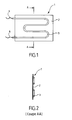
- the figure 2 shows that the electric heating resistance 3 is pressed against the surface of the diffuser 2, as visible on the Figures 3 and 4 ; the fixing of the heating resistor 3 can take place on a diffuser 2 plane ( figure 3 ), or on a diffuser 2 provided with a housing which matches a portion of the outer shape of the cylindrical heating electric heater 3 (cf. figure 4 ).
- the electric heating resistor 3 is here composed of an electric filament 4 mounted in a cylindrical tubular sheath 5 and surrounded by a dielectric insulating material (magnesia) disposed between the electric filament 4 and the sheath 5.
- a dielectric insulating material magnesia
- the heating resistor 3 is here fixed to the surface of the diffuser 2 by means of welds, made by mutual melting of the metals (and not by addition of additional metal) constituting the diffuser 2 and the sheath 5 of the heating resistor, the welding zones. 7 being arranged according to one of the generatrices of the resistance, and spaced apart from each other.
- the diffuser 2 may be in the form of a corrugated plate having corrugations approximately perpendicular to the median axis of the rectilinear sections of the heating resistor 3, as shown in the sectional view of the FIG. figure 5 .
- the welding zones 7 are then formed at the level of bulges of the undulations closest to the resistance. Between these welding zones 7 can thus take place an expansion of the metal of the diffuser, without damaging the quality of the welds.
- These corrugations can be very thin, with a spacing of the order of a millimeter, for example.
- the figure 6 shows the disposition of a heating body 1 within the casing 8 forming the whole of the heating apparatus.
- the diffuser 2 is disposed near the internal front wall 10 of the casing 8, in its lower part.
- the heating resistor 3 is welded to the rear face of the diffuser 2, oriented towards the rear wall 11 of the casing 8.
- the height of the diffuser plate is 245 mm for a length of 460 mm.
- the electrical resistor has three elbows, defining four single parallel straight segments spaced about 70 mm apart.
- the arrangement of the electrical resistance 3 thus bent, further facilitates the connection to the power supply, the connections 6 being on the same side of the heating body 1 (see left side on the figure 1 ).
- thermo conductivity 237 W / mK thermo conductivity 237 W / mK
- the diffuser of substantially flat shape comprises series of bosses 20 made by point stampings of the plate forming the diffuser. These bosses are spaced every 20 to 60 mm approximately.
- the sheath of the electrical resistance 3 is in contact with the diffuser 2 only at the bosses 20.
- the electrodes 21 and 22 located on either side of the diffuser / electrical resistance assembly allow the passage of the current only at the contact areas between the sheath and the diffuser 2, that is to say exclusively at the bosses 20 thus creating precise and localized welding areas.
- bosses 20 are crushed during the approach of the two electrodes 21 and 22 of each other according to the arrows F1 and F2. These flattening of the bosses allow the sheath 5 of the resistor 3 to be, after soldering, in linear contact with the flat surface of the diffuser 2 (see FIGS. Figures 10A and 10B ).
Landscapes
- Engineering & Computer Science (AREA)
- Mechanical Engineering (AREA)
- Physics & Mathematics (AREA)
- Thermal Sciences (AREA)
- Chemical & Material Sciences (AREA)
- Combustion & Propulsion (AREA)
- General Engineering & Computer Science (AREA)
- Resistance Heating (AREA)
- Surface Heating Bodies (AREA)
- Central Heating Systems (AREA)
Description
La présente invention concerne le domaine des appareils de chauffage électrique de locaux, et plus particulièrement les appareils à corps de chauffe incluant une résistance électrique.The present invention relates to the field of electric space heating appliances, and more particularly the apparatus with heating bodies including an electrical resistance.
Dans les appareils de chauffage électrique classiques, notamment dans les panneaux rayonnants, le chauffage est assuré par un corps de chauffe formé d'une ou plusieurs résistance(s) électrique(s) associée(s) à un ou plusieurs diffuseur(s) incorporé(s) dans une enveloppe généralement métallique, et disposé à proximité de la paroi frontale interne de ladite enveloppe.In conventional electric heating appliances, especially in radiant panels, heating is provided by a heating body formed of one or more electrical resistance (s) associated with one or more incorporated diffuser (s) (s) in a generally metallic envelope, and disposed near the inner end wall of said envelope.
La plupart des corps de chauffe actuels sont réalisés en utilisant en tant que diffuseur thermique des profilés en aluminium extrudé. Ces profilés intègrent, dans des logements longitudinaux de forme tubulaire, des résistances chauffantes électriques disposées selon l'axe longitudinal de ces logements et constituées d'un fil métallique bobiné, noyé dans des grains de magnésie compactés. La magnésie, conducteur thermique et bon isolant diélectrique, assure ainsi sans danger le transfert de chaleur du fil métallique vers le diffuseur.Most of the current heating elements are made using extruded aluminum profiles as thermal diffusers. These profiles incorporate, in longitudinal housing of tubular form, electric heating resistors arranged along the longitudinal axis of these housings and consisting of a wound wire, embedded in compacted grains of magnesia. Magnesia, thermal conductor and good dielectric insulator, thus safely ensures the transfer of heat from the wire to the diffuser.
D'autres corps de chauffe utilisent en tant que diffuseur des plaques de mica, un matériau à base de silicate. Deux plaques de mica sont collées l'une à l'autre et prennent en sandwich une résistance électrique chauffante constituée d'une feuille métallique reliée à l'alimentation électrique.Other heaters use as a diffuser mica plates, a silicate-based material. Two plates of mica are glued to each other and sandwich a heating electric resistance consisting of a metal sheet connected to the power supply.
Ces corps de chauffe fonctionnent de manière satisfaisante mais sont d'un coût relativement élevé de par leur structure nécessitant l'incorporation, lors de la fabrication, des fils ou feuilles métalliques chauffants à l'intérieur des logements ménagés dans les diffuseurs. De plus, lesdits logements doivent être de forme simple pour une fabrication et un montage aisé, imposant généralement une forme rectiligne.These heaters operate satisfactorily but are relatively expensive in their structure requiring the incorporation, during manufacture, son or heated metal foils inside the housings in the diffusers. In addition, said housings must be simple in shape for easy manufacture and assembly, generally imposing a rectilinear shape.
Lorsque l'on souhaite augmenter la puissance de chauffe, il est alors nécessaire d'introduire une multiplicité de résistances rectilignes, reliées en parallèles à l'alimentation électrique, et en conséquence d'aménager une multiplicité de logements dans un même diffuseur, ou la multiplication des diffuseurs dans un même appareil.When it is desired to increase the heating power, it is then necessary to introduce a multiplicity of rectilinear resistors, connected in parallel to the power supply, and consequently to accommodate a multiplicity of housings in the same diffuser, or the multiplication of the diffusers in the same apparatus.
On connaît de
La présente invention a donc pour but de proposer un nouveau type de corps de chauffe pour appareils de chauffage à structure simplifiée et à fabrication à coûts réduits, sans réduction des performances thermiques.The present invention therefore aims to provide a new type of heater for simplified structure heaters and low cost manufacturing, without reducing thermal performance.
A cet effet, la présente invention propose un corps de chauffe pour appareil de chauffage électrique de locaux, du type comportant au moins une résistance électrique chauffante constituée d'une gaine métallique, incorporant un fil métallique bobiné, noyé dans un isolant diélectrique, la résistance électrique étant fixée par soudure de la gaine métallique sur la surface d'au moins une des faces d'un diffuseur métallique se présentant sensiblement sous la forme d'une plaque, caractérisé en ce que le diffuseur et la gaine de la résistance chauffante sont en acier et sont soudés l'un à l'autre par fusion mutuelle des métaux les constituant au niveau de la zone de soudure, sans ajout de métal supplémentaire, la surface du diffuseur présentant, avant soudure, des bossages, la gaine de la résistance électrique étant soudée au diffuseur exclusivement au niveau desdits bossages.For this purpose, the present invention proposes a heater for an electric space heater, of the type comprising at least one electric heating element constituted by a metallic sheath, incorporating a wound wire, embedded in a dielectric insulator, the resistance electrical connection being fixed by welding of the metal sheath to the surface of at least one of the faces of a metal diffuser substantially in the form of a plate, characterized in that the diffuser and the sheath of the heating resistor are in steel and are welded to one another by mutual fusion of the metals constituting them at the weld zone, without adding additional metal, the surface of the diffuser having, before welding, bosses, the sheath of the electrical resistance being welded to the diffuser exclusively at said bosses.
Le diffuseur peut donc être de forme très simple, puisqu'il peut se présenter sous la forme d'une plaque unique. Ainsi, la résistance électrique n'a pas à s'adapter à une configuration particulière d'un logement ni inversement, il n'est pas nécessaire de ménager un logement pour la résistance au sein du diffuseur. Cette résistance peut donc être de forme quelconque.The diffuser can therefore be very simple form, since it can be in the form of a single plate. Thus, the electrical resistance does not have to adapt to a particular configuration of a housing or vice versa, it is not necessary to provide a housing for the resistance within the diffuser. This resistance can therefore be of any shape.
La résistance électrique est donc fixée à l'extérieur du diffuseur et non incorporée à l'intérieur de ce dernier. En conséquence, la réalisation du corps de chauffe est considérablement simplifiée puisqu'elle consiste essentiellement à fixer par soudure sans ajout de métal supplémentaire, la résistance électrique à une face extérieure du diffuseur.The electrical resistance is therefore attached to the outside of the diffuser and not incorporated inside the latter. As a result, the realization of the body The heating system is considerably simplified since it consists essentially of fixing by welding without adding additional metal, the electrical resistance to an outer face of the diffuser.
La résistance électrique est constituée d'une gaine métallique en acier, généralement tubulaire dans laquelle est incorporé un fil métallique bobiné noyé par exemple dans des grains de magnésie compactés.The electrical resistance consists of a steel sheath, generally tubular in which is incorporated a coiled wire embedded for example in compacted grains of magnesia.
Afin de permettre un contact intime de la résistance électrique avec le diffuseur, et notamment une continuité métallique de l'assemblage entre ces deux éléments, la soudure est réalisée à température élevée, par fusion mutuelle des métaux constituant le diffuseur et la gaine de la résistance électrique, au niveau de la zone de soudure.In order to allow an intimate contact of the electrical resistance with the diffuser, and in particular a metallic continuity of the assembly between these two elements, the welding is carried out at high temperature, by mutual fusion of the metals constituting the diffuser and the sheath of the resistance. electric, at the level of the weld zone.
Cette fusion mutuelle des métaux constituant le diffuseur et la gaine de la résistance électrique est favorisée par le fait que ces derniers sont de même nature à savoir en acier, avantageusement de composition sensiblement identique. L'acier est en outre un métal meilleur marché que l'aluminium.This mutual fusion of the metals constituting the diffuser and the sheath of the electrical resistance is favored by the fact that the latter are of the same kind, namely steel, advantageously of substantially identical composition. Steel is also a cheaper metal than aluminum.
Selon l'invention, les bossages sont présents à la surface du diffuseur et non, comme mentionné dans le brevet
Il est en outre préféré que le corps de chauffe comporte une résistance électrique chauffante unique, afin de limiter le nombre de connexions à l'alimentation électrique. En ce qui concerne la configuration générale de ladite résistance électrique chauffante, elle peut alors être formée d'un seul tronçon rectiligne, ou de plusieurs tronçons rectilignes reliés par au moins un tronçon courbe. La résistance serpente ainsi au contact direct de la surface d'au moins une face latérale du diffuseur, de manière à transmettre et à répartir, par conduction, ses calories à l'ensemble du diffuseur.It is furthermore preferred that the heating body comprises a single electric heating resistor in order to limit the number of connections to the power supply. As regards the general configuration of said electric heating resistance, it can then be formed of a single straight section, or of several straight sections connected by at least one curved section. The resistance thus winds in direct contact with the surface of at least one side face of the diffuser, so as to transmit and distribute, by conduction, its calories to the entire diffuser.
Le diffuseur peut être une plaque métallique de forme générale plane. Il peut également être une plaque métallique ondulée présentant des ondulations sensiblement perpendiculaires au(x) tronçon(s) rectiligne(s) de la résistance électrique.The diffuser may be a metal plate of generally flat shape. It may also be a corrugated metal plate having corrugations substantially perpendicular to the (s) straight section (s) of the electrical resistance.
De préférence, les ondulations sont situées entre les zones de soudure. Ces ondulations servent de "soufflets" de dilatation de la plaque entre les zones de soudures de la gaine de la résistance électrique.Preferably, the corrugations are located between the welding zones. These corrugations serve as "bellows" of expansion of the plate between the weld zones of the sheath of the electrical resistance.
Dans le cas où les ondulations sont uniformément réparties, les régions en saillie (renflements) vis-à-vis de la résistance électrique peuvent constituer des zones de soudure (correspondant aux bossages précités), les régions en creux s'éloignant de la résistance électrique servant de zones de dilatations éventuelles.In the case where the corrugations are uniformly distributed, the protruding regions (bulges) vis-à-vis the electrical resistance may constitute solder areas (corresponding to the aforementioned bosses), the recessed regions away from the electrical resistance serving as zones of possible dilatations.
En variante, des ondulations éventuelles parallèles aux tronçons rectilignes de la résistance peuvent constituer des logements partiels pour cesdits tronçons en vue d'augmenter le contact périphérique de la résistance avec la surface du diffuseur, et éventuellement accroître la zone de soudure possible.As a variant, possible corrugations parallel to the rectilinear sections of the resistor may constitute partial housings for these said sections in order to increase the peripheral contact of the resistor with the surface of the diffuser, and possibly to increase the possible welding area.
Selon un mode préféré de réalisation, le diffuseur est muni d'au moins un logement externe qui épouse au moins partiellement la forme de la résistance électrique chauffante, de manière à favoriser le transfert thermique.According to a preferred embodiment, the diffuser is provided with at least one outer housing that at least partially matches the shape of the electric heating element, so as to promote heat transfer.
La plaque métallique constituant le diffuseur peut être d'épaisseur réduite, comprise avantageusement entre 0,5 mm et 1 mm environ, permettant la réalisation d'un corps de chauffe relativement économique.The metal plate constituting the diffuser may be of reduced thickness, preferably between 0.5 mm and 1 mm, allowing the realization of a relatively economical heating body.
La présente invention concerne également un procédé de réalisation d'un corps de chauffe pour appareil de chauffage électrique, tel que décrit ci-dessus par soudure d'une résistance électrique chauffante sur un diffuseur, caractérisé en ce qu'il comprend les étapes successives suivantes :
- réalisation de bossages à la surface d'au moins une face du diffuseur,
- mise en place de la résistance électrique chauffante au contact du diffuseur uniquement au niveau des bossages,
- positionnement d'au moins une paire d'électrodes de soudure de part et d'autre de l'ensemble constitué par le diffuseur et la résistance électrique chauffante,
- application d'une tension électrique entre les deux électrodes, et d'une pression dans le sens d'un rapprochement des électrodes induisant un écrasement des bossages lors de la fusion mutuelle des métaux constitutifs du diffuseur et de la gaine de la résistance électrique.
- producing bosses on the surface of at least one face of the diffuser,
- setting up the electric heating resistance in contact with the diffuser only at the bosses,
- positioning at least one pair of welding electrodes on either side of the assembly constituted by the diffuser and the electric heating resistance,
- application of an electrical voltage between the two electrodes, and a pressure in the direction of an approximation of the electrodes inducing crushing of the bosses during the mutual fusion of the constituent metals of the diffuser and the sheath of the electrical resistance.
Ainsi, si le diffuseur est de forme sensiblement plane, la gaine de la résistance électrique arrive en contact linéique avec la surface de la face correspondante du diffuseur.Thus, if the diffuser is of substantially flat shape, the sheath of the electrical resistance comes into linear contact with the surface of the corresponding face of the diffuser.
Les bossages sont des déformations limitées du diffuseur réalisées par exemple au moyen d'un outil d'emboutissage. Ces bossages sont de préférence de forme oblongue orientée perpendiculairement à l'axe du tronçon correspondant de la résistance électrique (permettant une tolérance de positionnement de cette dernière) et présentent de préférence une surface supérieure arrondie. Cette surface arrondie permet de réduire au minimum la zone de contact entre la gaine de la résistance électrique et le bossage proprement dit, de manière à "concentrer" le passage du courant de soudure dans cette zone.The bosses are limited deformations of the diffuser made for example by means of a stamping tool. These bosses are preferably of oblong shape oriented perpendicularly to the axis of the corresponding section of the electrical resistance (allowing a positioning tolerance of the latter) and preferably have a rounded upper surface. This rounded surface minimizes the contact area between the sheath of the electrical resistance and the boss itself, so as to "focus" the passage of the welding current in this area.
Un tel procédé permet en particulier, avec des électrodes de plus grande longueur de réaliser simultanément plusieurs soudures au niveau de plusieurs bossages, et de réduire ainsi les cycles de fabrication du corps de chauffe.Such a method makes it possible in particular, with electrodes of greater length, to simultaneously produce several welds at a plurality of bosses, and thus to reduce the manufacturing cycles of the heating body.
La présente invention concerne également un appareil de chauffage électrique de locaux, caractérisé en ce qu'il comprend une enveloppe (ou caisson) incorporant un corps de chauffe selon l'invention, le diffuseur étant disposé à proximité de la paroi frontale interne de ladite enveloppe et la face du diffuseur opposée à celle recevant la résistance électrique par soudure étant orientée en direction de ladite paroi frontale de l'enveloppe.The present invention also relates to an electric space heating appliance, characterized in that it comprises a casing (or casing) incorporating a heating body according to the invention, the diffuser being disposed close to the internal front wall of said casing. and the face of the diffuser opposite to that receiving the electrical resistance by welding being oriented towards said front wall of the envelope.
Cet appareil de chauffage peut être un convecteur, un panneau rayonnant, un radiateur ou un sèche-serviettes. Dans le cas où l'appareil de chauffage constitue un panneau rayonnant, la face du diffuseur orientée vers la paroi frontale de l'enveloppe est recouverte d'un revêtement, de type peinture, augmentant l'émissivité de la surface de rayonnement dudit diffuseur.This heater may be a convector, a radiant panel, a radiator or a towel warmer. In the case where the heater is a radiating panel, the face of the diffuser facing the front wall of the casing is covered with a coating, paint type, increasing the emissivity of the radiation surface of said diffuser.
D'autres aspects et avantages de l'invention ressortiront de la description ci-après d'exemples de réalisation, non limitatifs, en référence aux planches de dessins annexées, dans lesquelles :
- la
figure 1 est une vue arrière d'un corps de chauffe, suivant l'invention, pour panneau rayonnant ; - la
figure 2 est une coupe transversale selon AA de lafigure 1 ; - les
figures 3 et 4 sont des coupes partielles présentant deux variantes de fixation de la résistance chauffante sur le diffuseur du corps de chauffe, selon l'invention ; - la
figure 5 est une coupe horizontale d'un diffuseur sous forme d'une plaque ondulée ; - la
figure 6 est une représentation schématique en coupe verticale d'un corps de chauffe incorporé dans un panneau rayonnant ; - les
figures 7 et 8 présentent les résultats de tests thermiques respectivement pour un corps de chauffe selon l'art antérieur (figure 7 ) et la présente invention (figure 8 ), sous forme d'isothermes de la face frontale du diffuseur. - Les
figures 9A, 9B, 10A et 10B sont des représentations schématiques illustrant le procédé de mise en oeuvre de l'invention : lesfigures 9A et 9B avant soudure, lesfigures 10A et 10B après soudure, lesfigures 9A et 10A étant des vues de côté et lesfigures 9B et 10B des vues en coupe transversale.
- the
figure 1 is a rear view of a heating body, according to the invention, for radiating panel; - the
figure 2 is a cross section along AA of thefigure 1 ; - the
Figures 3 and 4 are partial sections having two variants of fixing the heating resistance on the diffuser of the heating body, according to the invention; - the
figure 5 is a horizontal section of a diffuser in the form of a corrugated plate; - the
figure 6 is a schematic representation in vertical section of a heater incorporated in a radiating panel; - the
Figures 7 and 8 present the results of thermal tests respectively for a heating element according to the prior art (figure 7 ) and the present invention (figure 8 ), in the form of isotherms of the front face of the diffuser. - The
FIGS. 9A, 9B, 10A and 10B are schematic representations illustrating the method of implementation of the invention:Figures 9A and 9B before welding,Figures 10A and 10B after welding,Figures 9A and 10A being side views and theFigures 9B and 10B cross-sectional views.
Le corps de chauffe 1 conforme à l'invention représenté sur la
Il est possible également, comme dans l'art antérieur (corps de chauffe constitué de profilés en aluminium extrudés), de prévoir un corps de chauffe pourvu de plusieurs résistances électriques chauffantes, disposées avantageusement parallèlement les unes aux autres. Dans ce cas, il est nécessaire de prévoir des connexions 6 à l'alimentation électrique pour chaque résistance chauffante.It is also possible, as in the prior art (heating body consisting of extruded aluminum profiles), to provide a heating body. provided with several heating electric resistances, arranged advantageously parallel to each other. In this case, it is necessary to provide
La
La résistance électrique 3 chauffante est ici composée d'un filament électrique 4 monté dans une gaine 5 tubulaire cylindrique et entouré d'un matériau isolant diélectrique (magnésie) disposé entre le filament électrique 4 et la gaine 5.The
La résistance chauffante 3 est ici fixée à la surface du diffuseur 2 au moyen de soudures, réalisées par fusion mutuelle des métaux (et non par ajout de métal supplémentaire) constituant le diffuseur 2 et la gaine 5 de la résistance chauffante, les zones de soudure 7 étant disposées selon l'une des génératrices de la résistance, et espacées les unes des autres.The
Selon une variante, le diffuseur 2 peut être sous la forme d'une plaque ondulée comportant des ondulations approximativement perpendiculaires à l'axe médian des tronçons rectilignes de la résistance chauffante 3, comme représenté sur la vue en coupe de la
La
A titre d'exemple, pour un corps de chauffe 1 de 500 mm par 300 mm :
- la résistance électrique chauffante 3 est une gaine tubulaire en acier d'un diamètre de 8 mm ;
- les zones de soudure 7 sont espacées de 20 mm à 60 mm ;
- le diffuseur 2 est constitué d'une plaque d'acier, d'une épaisseur de 0,5 à 1 mm.
- the
electric heating resistor 3 is a tubular steel sheath with a diameter of 8 mm; - the
weld zones 7 are spaced from 20 mm to 60 mm; - the
diffuser 2 consists of a steel plate with a thickness of 0.5 to 1 mm.
A titre d'exemple, pour un panneau rayonnant d'une puissance de 1000 W, la hauteur de la plaque du diffuseur est de 245 mm pour une longueur de 460 mm. La résistance électrique présente trois coudes, définissant quatre segments rectilignes uniques parallèles espacés d'environ 70 mm.By way of example, for a radiating panel with a power of 1000 W, the height of the diffuser plate is 245 mm for a length of 460 mm. The electrical resistor has three elbows, defining four single parallel straight segments spaced about 70 mm apart.
Comme le montrent les résultats des tests thermiques présentés sous forme d'isothermes 13 sur les
La disposition de la résistance électrique 3 ainsi coudée, facilite en outre le raccordement à l'alimentation électrique, les connexions 6 se situant du même côté du corps de chauffe 1 (cf. côté gauche sur la
Il est donc possible, avec un corps de chauffe mettant en oeuvre un métal à plus faible conductivité thermique (ici acier ∼ 46 W/m.K) et non extrudable d'obtenir des performances thermiques comparables à celles d'un corps de chauffe en aluminium extrudé (conductivité thermique 237 W/m.K) à un coût nettement réduit et avec une grande facilité de mise en oeuvre.It is therefore possible, with a heating body using a metal with lower thermal conductivity (here steel ~ 46 W / mK) and not extrudable to obtain thermal performance comparable to those of an extruded aluminum heating body (thermal conductivity 237 W / mK) at a significantly reduced cost and with great ease of implementation.
Selon une autre variante de l'invention, le diffuseur de forme sensiblement plane comporte des séries de bossages 20 réalisés par emboutissages ponctuels de la plaque formant le diffuseur. Ces bossages sont écartés tous les 20 à 60 mm environ.According to another variant of the invention, the diffuser of substantially flat shape comprises series of
La dimension de ces bossages est la suivante :
longueur environ 1 à 10 mmlargeur entre 1 et 2 mm environ- profondeur de l'emboutis comprise
entre 0,2 et 2 mm environ.
- length about 1 to 10 mm
- width between 1 and 2 mm
- depth of the stamping between 0.2 and 2 mm approximately.
Comme présenté sur les
Il est ainsi possible d'utiliser une paire d'électrodes de grande longueur disposées en vis-à-vis permettant de réaliser plusieurs soudures simultanément. Cette flexibilité à la fois dans le positionnement des électrodes et dans la multiplicité des zones de soudure réalisées permet un gain de temps appréciable lors de la fabrication.It is thus possible to use a pair of electrodes of great length arranged vis-à-vis for making several welds simultaneously. This flexibility both in the positioning of the electrodes and in the multiplicity of the weld zones produced saves considerable time during manufacture.
Pendant la soudure, les bossages 20 sont écrasés lors du rapprochement des deux électrodes 21 et 22 l'une de l'autre selon les flèches F1 et F2. Ces aplatissements des bossages permettent à la gaine 5 de la résistance 3 d'être, après soudure, en contact linéique avec la surface plane du diffuseur 2 (voir les
Claims (12)
- A heating element (1) for an electric heating appliance for premises, of the type including at least one electric heating resistance (3) made up of a metal sheath (5), incorporating a wound metal wire (4), embedded in a dielectric insulator (9), the electric resistance being fastened by welding of the metal sheath (5) on the surface of at least one of the faces of a metallic diffuser substantially in the shape of a plate,
characterized in that the diffuser and the sheath of the heating resistance are made from steel and are welded to one another by mutual fusion of the metals from which they are made up at the weld zone (7), without adding additional material,
the surface of the diffuser having bosses (20) before welding, the sheath of the electrical resistance (3) being welded to the diffuser (2) exclusively at said bosses (20). - The heating element (1) according to claim 1, characterized in that it includes a single electric heating resistance (3).
- The heating element according to claim 1 or 2, characterized in that the electric heating resistance (3) is formed from a single rectilinear segment or several rectilinear segments connected by at least one curved segment.
- The heating element according to any one of the preceding claims, characterized in that the diffuser (2) is a metal plate with a generally planar shape.
- The heating element according to claim 3, characterized in that the diffuser (2) is in the form of a corrugated metal plate having corrugations (12) substantially perpendicular to the rectilinear segment(s) of the electric resistance.
- The heating element according to claim 5, characterized in that the corrugations (12) are situated between the weld zones (7).
- The heating element according to any one of the preceding claims, characterized in that the diffuser (2) is provided with at least one outer housing that at least partially hugs the shape of the electric heating resistance (3).
- A method for manufacturing a heating element (1) for an electric heating apparatus for premises according to any one of the preceding claims by welding an electric heating resistance (3) on a diffuser (2), characterized in that it comprises the following successive steps:- producing bosses (20) on the surface of at least one face of the diffuser (2),- placing the electric heating resistance (3) in contact with the diffuser only at the bosses (20),- positioning at least one pair of welding electrodes (21, 22) on either side of the assembly made up of the diffuser and the electric heating resistance,- applying an electric voltage between the two electrodes (21, 22), and pressure in the direction bringing the electrodes closer together causing crushing of the bosses (20) during the mutual fusion of the metals making up the diffuser (2) and the sheath (5) of the electric resistance (3).
- An electric heating apparatus for premises, characterized in that it comprises an enclosure (8) incorporating a heating element (1) according to any one of claims 1 to 8.
- The electric heating apparatus for premises according to claim 9, characterized in that the diffuser (2) of the heating element (1) is positioned near the inner front wall (10) of said enclosure, and the face of the diffuser (2) opposite that receiving the electric resistance (3) by welding being oriented toward said front wall (10) of the enclosure (8).
- The heating apparatus according to claim 10, characterized in that it constitutes a radiating panel, the face of the diffuser (2) oriented toward the front wall (10) of the enclosure being covered with a coating, of the paint type, increasing the emissivity of the radiation surface of said diffuser (2).
- The heating apparatus according to claim 9 or 10, characterized in that said apparatus is a conductor, a panel heater, a radiator or a towel warmer.
Priority Applications (1)
| Application Number | Priority Date | Filing Date | Title |
|---|---|---|---|
| PL08290687T PL2015609T3 (en) | 2007-07-12 | 2008-07-11 | Heating element for a heating appliance, method of manufacturing the heating element and radiation heating appliance comprising such a heating element |
Applications Claiming Priority (1)
| Application Number | Priority Date | Filing Date | Title |
|---|---|---|---|
| FR0705072A FR2918836B1 (en) | 2007-07-12 | 2007-07-12 | HEATING BODY FOR HEATING APPARATUS, AND APPARATUS FOR HEATING PREMISES INCORPORATING SUCH HEATING BODY |
Publications (3)
| Publication Number | Publication Date |
|---|---|
| EP2015609A2 EP2015609A2 (en) | 2009-01-14 |
| EP2015609A3 EP2015609A3 (en) | 2009-11-04 |
| EP2015609B1 true EP2015609B1 (en) | 2014-11-19 |
Family
ID=38880991
Family Applications (1)
| Application Number | Title | Priority Date | Filing Date |
|---|---|---|---|
| EP08290687.6A Active EP2015609B1 (en) | 2007-07-12 | 2008-07-11 | Heating element for a heating appliance, method of manufacturing the heating element and radiation heating appliance comprising such a heating element |
Country Status (4)
| Country | Link |
|---|---|
| EP (1) | EP2015609B1 (en) |
| ES (1) | ES2530668T3 (en) |
| FR (1) | FR2918836B1 (en) |
| PL (1) | PL2015609T3 (en) |
Families Citing this family (1)
| Publication number | Priority date | Publication date | Assignee | Title |
|---|---|---|---|---|
| CN101749859B (en) * | 2010-02-11 | 2012-02-29 | 季连祥 | Horizontal side plate vertical type hot-blast furnace |
Family Cites Families (11)
| Publication number | Priority date | Publication date | Assignee | Title |
|---|---|---|---|---|
| US3117249A (en) * | 1960-02-16 | 1964-01-07 | Sperry Rand Corp | Embedded heater cathode |
| US3193659A (en) | 1962-03-26 | 1965-07-06 | Whirlpool Co | D-section tubing with welding projections thereon and method of forming the same |
| FR1465590A (en) * | 1965-11-30 | 1967-01-13 | Vulcain | Hot plates |
| FR2301780A1 (en) * | 1975-02-21 | 1976-09-17 | Sepro | ELECTRIC CONVECTOR |
| EP0102927B1 (en) * | 1982-09-03 | 1986-07-30 | Elpatronic Ag | Arrangement of projections and a method for multiple-projection welding |
| FI81473C (en) * | 1988-05-16 | 1990-10-10 | Loval Oy | UPPVAERMNINGSELEMENT FOER ELECTRIC RUMSUPPVAERMARE, SPECIELLT AV GENOMSTROEMNINGSTYP. |
| FR2632660B1 (en) * | 1988-06-08 | 1990-09-21 | Seb Sa | METHOD FOR FIXING A METAL TUBE ON A METAL SURFACE AND DEVICE THUS OBTAINED |
| DE3938895A1 (en) * | 1989-04-13 | 1991-05-29 | Karl Jacobi | Pig iron electro heating plate - is suitable for stationary or portable use with new heat surface on rear provided by corrugated metal plate |
| FR2730120B1 (en) * | 1995-02-01 | 1997-03-28 | Seb Sa | HEATING ELEMENT WITH DIFFUSING PLATE |
| FR2733383B1 (en) * | 1995-04-19 | 1997-06-06 | Seb Sa | HEATING ELEMENT ARM ON SUPPORT |
| FR2931427A1 (en) | 2008-05-26 | 2009-11-27 | Peugeot Citroen Automobiles Sa | Hybrid vehicle controlling method, involves controlling coupling device by control device decoupling electric machine from shaft when speed value is greater than reference speed threshold established from characteristic parameters of body |
-
2007
- 2007-07-12 FR FR0705072A patent/FR2918836B1/en active Active
-
2008
- 2008-07-11 PL PL08290687T patent/PL2015609T3/en unknown
- 2008-07-11 EP EP08290687.6A patent/EP2015609B1/en active Active
- 2008-07-11 ES ES08290687T patent/ES2530668T3/en active Active
Also Published As
| Publication number | Publication date |
|---|---|
| EP2015609A2 (en) | 2009-01-14 |
| ES2530668T3 (en) | 2015-03-04 |
| PL2015609T3 (en) | 2015-05-29 |
| FR2918836B1 (en) | 2011-01-14 |
| EP2015609A3 (en) | 2009-11-04 |
| FR2918836A1 (en) | 2009-01-16 |
Similar Documents
| Publication | Publication Date | Title |
|---|---|---|
| EP1145842B1 (en) | Laminated glazing | |
| EP2185046B1 (en) | Boiler for machine for the preparation of hot drinks | |
| EP2804516B1 (en) | Towel-drying radiator, at least one towel-holding bar of which has a built-in heat sink in which an electrical heating cable is accommodated | |
| EP0680585B1 (en) | Electric boiler for heat transfer liquid circulating in an open or closed system | |
| EP0017084A1 (en) | Thermoelectric device for heat transfer with liquid-flow circuit | |
| CH714027B1 (en) | Modular radiating element and method of manufacturing such an element. | |
| EP2015609B1 (en) | Heating element for a heating appliance, method of manufacturing the heating element and radiation heating appliance comprising such a heating element | |
| EP2251611A1 (en) | Modular element for radiator with heat-transfer fluid and electric radiator made up of at least one such element | |
| FR3066010B1 (en) | HEATING MODULE FOR ELECTRIC HEATING APPARATUS | |
| FR2908262A1 (en) | Ladder type towel drier radiator for use in e.g. bathroom, has heating panel with glass plate and heating element e.g. heating film, that is connected to power supply, where plate is made of electrical insulation material | |
| EP0225835B1 (en) | Electrical heating cable | |
| EP2400236A1 (en) | Electric heat-transfer fluid radiator module with cover | |
| WO2012001294A1 (en) | Heater rod comprising a casing in which at least one electrical resistance heating element is mounted | |
| EP2434246B1 (en) | Heat-exchange device, in particular for a car | |
| EP2109344A2 (en) | Heating body of an electric radiator comprising a metal filament with helical coiling with differentiated spire zones | |
| FR2631427A1 (en) | HEATING ELEMENT FOR AN ELECTRICAL RADIATOR FOR THE HEATING OF PREMISES, ESPECIALLY OF CONTINUOUS TYPE | |
| FR2611106A3 (en) | Plate-shaped electrical heating element | |
| EP0563955B1 (en) | Method of manufacturing a continuous heater for dispenser for hot beverages | |
| EP2072168A1 (en) | Method for welding tubular elements for a radiator with a heat-transfer fluid and radiator thus manufactured | |
| FR2463372A1 (en) | Thermocouple generator with heat exchanger - consists of air heater and water cooling coils fitted with thermocouple pads | |
| FR2691869A1 (en) | Flat and flexible heating element with integrated connection. | |
| FR2725105A1 (en) | Cylindrical heating element used in cartridge heaters e.g. for mould heating | |
| FR2716527A1 (en) | Heating procedure for building | |
| FR2958827A1 (en) | Electric heater for electric heating appliance, has U-shaped electric heat source whose leading edges increases coefficient of heat exchange and reduces temperature of heater while removing phenomenon of boundary layer | |
| FR3097953A1 (en) | Heating device for motor vehicle. |
Legal Events
| Date | Code | Title | Description |
|---|---|---|---|
| PUAI | Public reference made under article 153(3) epc to a published international application that has entered the european phase |
Free format text: ORIGINAL CODE: 0009012 |
|
| AK | Designated contracting states |
Kind code of ref document: A2 Designated state(s): AT BE BG CH CY CZ DE DK EE ES FI FR GB GR HR HU IE IS IT LI LT LU LV MC MT NL NO PL PT RO SE SI SK TR |
|
| AX | Request for extension of the european patent |
Extension state: AL BA MK RS |
|
| PUAL | Search report despatched |
Free format text: ORIGINAL CODE: 0009013 |
|
| AK | Designated contracting states |
Kind code of ref document: A3 Designated state(s): AT BE BG CH CY CZ DE DK EE ES FI FR GB GR HR HU IE IS IT LI LT LU LV MC MT NL NO PL PT RO SE SI SK TR |
|
| AX | Request for extension of the european patent |
Extension state: AL BA MK RS |
|
| 17P | Request for examination filed |
Effective date: 20100330 |
|
| 17Q | First examination report despatched |
Effective date: 20100429 |
|
| AKX | Designation fees paid |
Designated state(s): AT BE BG CH CY CZ DE DK EE ES FI FR GB GR HR HU IE IS IT LI LT LU LV MC MT NL NO PL PT RO SE SI SK TR |
|
| RIC1 | Information provided on ipc code assigned before grant |
Ipc: B23K 11/14 20060101ALI20101116BHEP Ipc: H05B 3/50 20060101AFI20101116BHEP Ipc: F24H 3/00 20060101ALI20101116BHEP |
|
| GRAP | Despatch of communication of intention to grant a patent |
Free format text: ORIGINAL CODE: EPIDOSNIGR1 |
|
| INTG | Intention to grant announced |
Effective date: 20140818 |
|
| RIN1 | Information on inventor provided before grant (corrected) |
Inventor name: AMINOT, VINCENT |
|
| GRAS | Grant fee paid |
Free format text: ORIGINAL CODE: EPIDOSNIGR3 |
|
| GRAA | (expected) grant |
Free format text: ORIGINAL CODE: 0009210 |
|
| AK | Designated contracting states |
Kind code of ref document: B1 Designated state(s): AT BE BG CH CY CZ DE DK EE ES FI FR GB GR HR HU IE IS IT LI LT LU LV MC MT NL NO PL PT RO SE SI SK TR |
|
| REG | Reference to a national code |
Ref country code: GB Ref legal event code: FG4D Free format text: NOT ENGLISH |
|
| REG | Reference to a national code |
Ref country code: CH Ref legal event code: EP |
|
| REG | Reference to a national code |
Ref country code: AT Ref legal event code: REF Ref document number: 697625 Country of ref document: AT Kind code of ref document: T Effective date: 20141215 |
|
| REG | Reference to a national code |
Ref country code: IE Ref legal event code: FG4D Free format text: LANGUAGE OF EP DOCUMENT: FRENCH |
|
| REG | Reference to a national code |
Ref country code: DE Ref legal event code: R096 Ref document number: 602008035437 Country of ref document: DE Effective date: 20141231 |
|
| REG | Reference to a national code |
Ref country code: RO Ref legal event code: EPE |
|
| REG | Reference to a national code |
Ref country code: ES Ref legal event code: FG2A Ref document number: 2530668 Country of ref document: ES Kind code of ref document: T3 Effective date: 20150304 |
|
| REG | Reference to a national code |
Ref country code: SE Ref legal event code: TRGR |
|
| REG | Reference to a national code |
Ref country code: NL Ref legal event code: VDEP Effective date: 20141119 |
|
| REG | Reference to a national code |
Ref country code: AT Ref legal event code: MK05 Ref document number: 697625 Country of ref document: AT Kind code of ref document: T Effective date: 20141119 |
|
| REG | Reference to a national code |
Ref country code: LT Ref legal event code: MG4D |
|
| PG25 | Lapsed in a contracting state [announced via postgrant information from national office to epo] |
Ref country code: FI Free format text: LAPSE BECAUSE OF FAILURE TO SUBMIT A TRANSLATION OF THE DESCRIPTION OR TO PAY THE FEE WITHIN THE PRESCRIBED TIME-LIMIT Effective date: 20141119 Ref country code: PT Free format text: LAPSE BECAUSE OF FAILURE TO SUBMIT A TRANSLATION OF THE DESCRIPTION OR TO PAY THE FEE WITHIN THE PRESCRIBED TIME-LIMIT Effective date: 20150319 Ref country code: LT Free format text: LAPSE BECAUSE OF FAILURE TO SUBMIT A TRANSLATION OF THE DESCRIPTION OR TO PAY THE FEE WITHIN THE PRESCRIBED TIME-LIMIT Effective date: 20141119 Ref country code: NL Free format text: LAPSE BECAUSE OF FAILURE TO SUBMIT A TRANSLATION OF THE DESCRIPTION OR TO PAY THE FEE WITHIN THE PRESCRIBED TIME-LIMIT Effective date: 20141119 Ref country code: NO Free format text: LAPSE BECAUSE OF FAILURE TO SUBMIT A TRANSLATION OF THE DESCRIPTION OR TO PAY THE FEE WITHIN THE PRESCRIBED TIME-LIMIT Effective date: 20150219 Ref country code: IS Free format text: LAPSE BECAUSE OF FAILURE TO SUBMIT A TRANSLATION OF THE DESCRIPTION OR TO PAY THE FEE WITHIN THE PRESCRIBED TIME-LIMIT Effective date: 20150319 |
|
| PG25 | Lapsed in a contracting state [announced via postgrant information from national office to epo] |
Ref country code: CY Free format text: LAPSE BECAUSE OF FAILURE TO SUBMIT A TRANSLATION OF THE DESCRIPTION OR TO PAY THE FEE WITHIN THE PRESCRIBED TIME-LIMIT Effective date: 20141119 Ref country code: GR Free format text: LAPSE BECAUSE OF FAILURE TO SUBMIT A TRANSLATION OF THE DESCRIPTION OR TO PAY THE FEE WITHIN THE PRESCRIBED TIME-LIMIT Effective date: 20150220 Ref country code: HR Free format text: LAPSE BECAUSE OF FAILURE TO SUBMIT A TRANSLATION OF THE DESCRIPTION OR TO PAY THE FEE WITHIN THE PRESCRIBED TIME-LIMIT Effective date: 20141119 Ref country code: LV Free format text: LAPSE BECAUSE OF FAILURE TO SUBMIT A TRANSLATION OF THE DESCRIPTION OR TO PAY THE FEE WITHIN THE PRESCRIBED TIME-LIMIT Effective date: 20141119 Ref country code: AT Free format text: LAPSE BECAUSE OF FAILURE TO SUBMIT A TRANSLATION OF THE DESCRIPTION OR TO PAY THE FEE WITHIN THE PRESCRIBED TIME-LIMIT Effective date: 20141119 |
|
| REG | Reference to a national code |
Ref country code: PL Ref legal event code: T3 |
|
| REG | Reference to a national code |
Ref country code: FR Ref legal event code: PLFP Year of fee payment: 8 |
|
| PG25 | Lapsed in a contracting state [announced via postgrant information from national office to epo] |
Ref country code: EE Free format text: LAPSE BECAUSE OF FAILURE TO SUBMIT A TRANSLATION OF THE DESCRIPTION OR TO PAY THE FEE WITHIN THE PRESCRIBED TIME-LIMIT Effective date: 20141119 Ref country code: DK Free format text: LAPSE BECAUSE OF FAILURE TO SUBMIT A TRANSLATION OF THE DESCRIPTION OR TO PAY THE FEE WITHIN THE PRESCRIBED TIME-LIMIT Effective date: 20141119 Ref country code: CZ Free format text: LAPSE BECAUSE OF FAILURE TO SUBMIT A TRANSLATION OF THE DESCRIPTION OR TO PAY THE FEE WITHIN THE PRESCRIBED TIME-LIMIT Effective date: 20141119 Ref country code: SK Free format text: LAPSE BECAUSE OF FAILURE TO SUBMIT A TRANSLATION OF THE DESCRIPTION OR TO PAY THE FEE WITHIN THE PRESCRIBED TIME-LIMIT Effective date: 20141119 |
|
| REG | Reference to a national code |
Ref country code: DE Ref legal event code: R097 Ref document number: 602008035437 Country of ref document: DE |
|
| PLBE | No opposition filed within time limit |
Free format text: ORIGINAL CODE: 0009261 |
|
| STAA | Information on the status of an ep patent application or granted ep patent |
Free format text: STATUS: NO OPPOSITION FILED WITHIN TIME LIMIT |
|
| 26N | No opposition filed |
Effective date: 20150820 |
|
| PG25 | Lapsed in a contracting state [announced via postgrant information from national office to epo] |
Ref country code: IT Free format text: LAPSE BECAUSE OF FAILURE TO SUBMIT A TRANSLATION OF THE DESCRIPTION OR TO PAY THE FEE WITHIN THE PRESCRIBED TIME-LIMIT Effective date: 20141119 |
|
| REG | Reference to a national code |
Ref country code: DE Ref legal event code: R119 Ref document number: 602008035437 Country of ref document: DE |
|
| PG25 | Lapsed in a contracting state [announced via postgrant information from national office to epo] |
Ref country code: MC Free format text: LAPSE BECAUSE OF FAILURE TO SUBMIT A TRANSLATION OF THE DESCRIPTION OR TO PAY THE FEE WITHIN THE PRESCRIBED TIME-LIMIT Effective date: 20141119 Ref country code: SI Free format text: LAPSE BECAUSE OF FAILURE TO SUBMIT A TRANSLATION OF THE DESCRIPTION OR TO PAY THE FEE WITHIN THE PRESCRIBED TIME-LIMIT Effective date: 20141119 |
|
| REG | Reference to a national code |
Ref country code: CH Ref legal event code: PL |
|
| GBPC | Gb: european patent ceased through non-payment of renewal fee |
Effective date: 20150711 |
|
| PG25 | Lapsed in a contracting state [announced via postgrant information from national office to epo] |
Ref country code: LU Free format text: LAPSE BECAUSE OF FAILURE TO SUBMIT A TRANSLATION OF THE DESCRIPTION OR TO PAY THE FEE WITHIN THE PRESCRIBED TIME-LIMIT Effective date: 20150711 |
|
| REG | Reference to a national code |
Ref country code: IE Ref legal event code: MM4A |
|
| PG25 | Lapsed in a contracting state [announced via postgrant information from national office to epo] |
Ref country code: CH Free format text: LAPSE BECAUSE OF NON-PAYMENT OF DUE FEES Effective date: 20150731 Ref country code: DE Free format text: LAPSE BECAUSE OF NON-PAYMENT OF DUE FEES Effective date: 20160202 Ref country code: LI Free format text: LAPSE BECAUSE OF NON-PAYMENT OF DUE FEES Effective date: 20150731 Ref country code: GB Free format text: LAPSE BECAUSE OF NON-PAYMENT OF DUE FEES Effective date: 20150711 |
|
| REG | Reference to a national code |
Ref country code: FR Ref legal event code: PLFP Year of fee payment: 9 |
|
| PG25 | Lapsed in a contracting state [announced via postgrant information from national office to epo] |
Ref country code: IE Free format text: LAPSE BECAUSE OF NON-PAYMENT OF DUE FEES Effective date: 20150711 |
|
| PGFP | Annual fee paid to national office [announced via postgrant information from national office to epo] |
Ref country code: ES Payment date: 20160715 Year of fee payment: 9 |
|
| PG25 | Lapsed in a contracting state [announced via postgrant information from national office to epo] |
Ref country code: MT Free format text: LAPSE BECAUSE OF FAILURE TO SUBMIT A TRANSLATION OF THE DESCRIPTION OR TO PAY THE FEE WITHIN THE PRESCRIBED TIME-LIMIT Effective date: 20141119 |
|
| PG25 | Lapsed in a contracting state [announced via postgrant information from national office to epo] |
Ref country code: BG Free format text: LAPSE BECAUSE OF FAILURE TO SUBMIT A TRANSLATION OF THE DESCRIPTION OR TO PAY THE FEE WITHIN THE PRESCRIBED TIME-LIMIT Effective date: 20141119 Ref country code: HU Free format text: LAPSE BECAUSE OF FAILURE TO SUBMIT A TRANSLATION OF THE DESCRIPTION OR TO PAY THE FEE WITHIN THE PRESCRIBED TIME-LIMIT; INVALID AB INITIO Effective date: 20080711 |
|
| REG | Reference to a national code |
Ref country code: FR Ref legal event code: PLFP Year of fee payment: 10 |
|
| PG25 | Lapsed in a contracting state [announced via postgrant information from national office to epo] |
Ref country code: BE Free format text: LAPSE BECAUSE OF NON-PAYMENT OF DUE FEES Effective date: 20150731 |
|
| PGFP | Annual fee paid to national office [announced via postgrant information from national office to epo] |
Ref country code: BE Payment date: 20170609 Year of fee payment: 16 |
|
| REG | Reference to a national code |
Ref country code: ES Ref legal event code: FD2A Effective date: 20181106 |
|
| PG25 | Lapsed in a contracting state [announced via postgrant information from national office to epo] |
Ref country code: ES Free format text: LAPSE BECAUSE OF NON-PAYMENT OF DUE FEES Effective date: 20170712 |
|
| PG25 | Lapsed in a contracting state [announced via postgrant information from national office to epo] |
Ref country code: FR Free format text: LAPSE BECAUSE OF NON-PAYMENT OF DUE FEES Effective date: 20180731 |
|
| PGFP | Annual fee paid to national office [announced via postgrant information from national office to epo] |
Ref country code: TR Payment date: 20200709 Year of fee payment: 13 |
|
| PGFP | Annual fee paid to national office [announced via postgrant information from national office to epo] |
Ref country code: PL Payment date: 20200702 Year of fee payment: 13 |
|
| PG25 | Lapsed in a contracting state [announced via postgrant information from national office to epo] |
Ref country code: PL Free format text: LAPSE BECAUSE OF NON-PAYMENT OF DUE FEES Effective date: 20210711 |
|
| PGFP | Annual fee paid to national office [announced via postgrant information from national office to epo] |
Ref country code: RO Payment date: 20230706 Year of fee payment: 16 |
|
| PGFP | Annual fee paid to national office [announced via postgrant information from national office to epo] |
Ref country code: SE Payment date: 20230719 Year of fee payment: 16 |