EP2015124A1 - Chirurgisches Mikroskopiesystem und Bildgebungsverfahren - Google Patents
Chirurgisches Mikroskopiesystem und Bildgebungsverfahren Download PDFInfo
- Publication number
- EP2015124A1 EP2015124A1 EP08009562A EP08009562A EP2015124A1 EP 2015124 A1 EP2015124 A1 EP 2015124A1 EP 08009562 A EP08009562 A EP 08009562A EP 08009562 A EP08009562 A EP 08009562A EP 2015124 A1 EP2015124 A1 EP 2015124A1
- Authority
- EP
- European Patent Office
- Prior art keywords
- light
- illumination
- spectral filter
- beam path
- illumination beam
- Prior art date
- Legal status (The legal status is an assumption and is not a legal conclusion. Google has not performed a legal analysis and makes no representation as to the accuracy of the status listed.)
- Withdrawn
Links
- 238000000386 microscopy Methods 0.000 title claims abstract description 33
- 238000003384 imaging method Methods 0.000 title claims abstract description 28
- 238000005286 illumination Methods 0.000 claims abstract description 184
- 230000003595 spectral effect Effects 0.000 claims abstract description 150
- 229910052724 xenon Inorganic materials 0.000 claims abstract description 60
- FHNFHKCVQCLJFQ-UHFFFAOYSA-N xenon atom Chemical compound [Xe] FHNFHKCVQCLJFQ-UHFFFAOYSA-N 0.000 claims abstract description 60
- 230000005540 biological transmission Effects 0.000 claims abstract description 15
- 230000003287 optical effect Effects 0.000 claims description 21
- 238000000034 method Methods 0.000 claims description 11
- 238000012634 optical imaging Methods 0.000 claims description 9
- 239000000758 substrate Substances 0.000 claims description 6
- 239000003989 dielectric material Substances 0.000 claims description 4
- 238000000295 emission spectrum Methods 0.000 description 9
- 229910052736 halogen Inorganic materials 0.000 description 9
- 150000002367 halogens Chemical class 0.000 description 9
- GWEVSGVZZGPLCZ-UHFFFAOYSA-N Titan oxide Chemical compound O=[Ti]=O GWEVSGVZZGPLCZ-UHFFFAOYSA-N 0.000 description 8
- 238000001228 spectrum Methods 0.000 description 8
- 238000001356 surgical procedure Methods 0.000 description 6
- 238000010586 diagram Methods 0.000 description 5
- 230000000694 effects Effects 0.000 description 5
- VYPSYNLAJGMNEJ-UHFFFAOYSA-N Silicium dioxide Chemical compound O=[Si]=O VYPSYNLAJGMNEJ-UHFFFAOYSA-N 0.000 description 4
- 230000001902 propagating effect Effects 0.000 description 3
- 230000009286 beneficial effect Effects 0.000 description 2
- 239000002775 capsule Substances 0.000 description 2
- 229910052681 coesite Inorganic materials 0.000 description 2
- 210000004087 cornea Anatomy 0.000 description 2
- 229910052906 cristobalite Inorganic materials 0.000 description 2
- 230000003247 decreasing effect Effects 0.000 description 2
- 230000001419 dependent effect Effects 0.000 description 2
- 238000006073 displacement reaction Methods 0.000 description 2
- 230000004048 modification Effects 0.000 description 2
- 238000012986 modification Methods 0.000 description 2
- 230000011514 reflex Effects 0.000 description 2
- 210000001525 retina Anatomy 0.000 description 2
- 239000000377 silicon dioxide Substances 0.000 description 2
- 229910052682 stishovite Inorganic materials 0.000 description 2
- 229910052905 tridymite Inorganic materials 0.000 description 2
- 210000004127 vitreous body Anatomy 0.000 description 2
- 230000003321 amplification Effects 0.000 description 1
- 238000000149 argon plasma sintering Methods 0.000 description 1
- 229910052729 chemical element Inorganic materials 0.000 description 1
- 238000006243 chemical reaction Methods 0.000 description 1
- 230000005284 excitation Effects 0.000 description 1
- 238000010438 heat treatment Methods 0.000 description 1
- 239000000463 material Substances 0.000 description 1
- 239000012528 membrane Substances 0.000 description 1
- QSHDDOUJBYECFT-UHFFFAOYSA-N mercury Chemical compound [Hg] QSHDDOUJBYECFT-UHFFFAOYSA-N 0.000 description 1
- 229910052753 mercury Inorganic materials 0.000 description 1
- 229910052751 metal Inorganic materials 0.000 description 1
- 239000002184 metal Substances 0.000 description 1
- 238000003199 nucleic acid amplification method Methods 0.000 description 1
- 201000005111 ocular hyperemia Diseases 0.000 description 1
- 230000005855 radiation Effects 0.000 description 1
- 230000006798 recombination Effects 0.000 description 1
- 238000005215 recombination Methods 0.000 description 1
- 238000009834 vaporization Methods 0.000 description 1
Images


Classifications
-
- G—PHYSICS
- G02—OPTICS
- G02B—OPTICAL ELEMENTS, SYSTEMS OR APPARATUS
- G02B21/00—Microscopes
- G02B21/0004—Microscopes specially adapted for specific applications
- G02B21/0012—Surgical microscopes
-
- A—HUMAN NECESSITIES
- A61—MEDICAL OR VETERINARY SCIENCE; HYGIENE
- A61B—DIAGNOSIS; SURGERY; IDENTIFICATION
- A61B3/00—Apparatus for testing the eyes; Instruments for examining the eyes
- A61B3/10—Objective types, i.e. instruments for examining the eyes independent of the patients' perceptions or reactions
- A61B3/13—Ophthalmic microscopes
- A61B3/132—Ophthalmic microscopes in binocular arrangement
-
- A—HUMAN NECESSITIES
- A61—MEDICAL OR VETERINARY SCIENCE; HYGIENE
- A61B—DIAGNOSIS; SURGERY; IDENTIFICATION
- A61B90/00—Instruments, implements or accessories specially adapted for surgery or diagnosis and not covered by any of the groups A61B1/00 - A61B50/00, e.g. for luxation treatment or for protecting wound edges
- A61B90/36—Image-producing devices or illumination devices not otherwise provided for
-
- G—PHYSICS
- G02—OPTICS
- G02B—OPTICAL ELEMENTS, SYSTEMS OR APPARATUS
- G02B5/00—Optical elements other than lenses
- G02B5/20—Filters
- G02B5/28—Interference filters
-
- A—HUMAN NECESSITIES
- A61—MEDICAL OR VETERINARY SCIENCE; HYGIENE
- A61B—DIAGNOSIS; SURGERY; IDENTIFICATION
- A61B90/00—Instruments, implements or accessories specially adapted for surgery or diagnosis and not covered by any of the groups A61B1/00 - A61B50/00, e.g. for luxation treatment or for protecting wound edges
- A61B90/20—Surgical microscopes characterised by non-optical aspects
Definitions
- the present invention relates to a surgical microscopy system and to an imaging method. Further the present invention relates to a surgical microscopy system having an illumination system and to a method of usage of the same. In particular, the present invention relates to a surgical microscopy system having an illumination system suitable for ophthalmologic surgeries.
- a surgical microscope for ophthalmology wherein a xenon illumination light source or a metal halogenide illumination light source is used for illuminating an object.
- illumination light sources are integrated into the surgical microscope so that a purchaser of such a surgical microscope has to decide in favour of one of the illumination light sources.
- conventional surgical microscope has disadvantages.
- the present invention has been accomplished taking the above problems into consideration.
- An object of the present invention is, to provide a surgical microscope which is capable to image structures having different optical characteristics in the human eye.
- a further object of the present invention is to provide a method to image these structures having different optical characteristics during an ophthalmologic surgery.
- ⁇ represents a wavelength of the illumination light and A( ⁇ ) represents a ratio between an intensity of light emanating from the spectral filter along the illumination beam path and an intensity of light coming from the xenon gas discharge lamp and being incident onto the spectral filter. ⁇ b thereby is greater or equal to zero.
- f in the above relation represents a general attenuation of light filtered by the spectral filter, wherein the attenuation factor is constant in the wavelength range between 400 nm and 700 nm.
- the factor f being a constant attenuation factor does not influence a shape of a spectrum of light emanating from the spectral filter but does merely effect an overall intensity of light having the spectrum.
- an object region is imaged.
- the object region is understood to be a region where an illuminated region of an object overlaps with an imaged region of the object.
- the illuminating the object region with illumination light is carried out along an illumination beam path.
- the illumination beam path thereby indicates a path of light emanating from the xenon gas discharge lamp and being incident onto the object region.
- the illumination beam path may thereby comprise a plurality of straight, and also not parallel sections.
- the optical imaging system is understood to be an optical system comprising a plurality of optical elements, such as lenses and/or mirrors which are arranged and adapted to generate an image from the object region.
- the image may for example be an intermediate image in an optical system which in turn is imaged to the retina of an observer, or it may for example be an image generated by a camera and displayed on a display device. Further, the image may be acquired by a camera and may be projected onto a screen.
- a xenon gas discharge lamp comprises a light source in which by electron excitation and recombination processes in a plasma light is generated in a volume containing xenon.
- the xenon gas discharge lamp may comprise a bulb filled with xenon gas.
- the filling of the bulb may contain further chemical elements, such as mercury, amounting to at most a fraction of a total weight of elements filled into the bulb of 5 weight percent.
- two electrodes are provided across which a high voltage pulse may be applied for starting the lamp.
- Particularly advantageous for a surgical microscopy system are such xenon gas discharge lamps in which a predominant portion of light is generated in small volumes around the two electrodes.
- a spectral characteristics of light of a xenon gas discharge lamp is very similar to a spectral characteristics of daylight. This daylight similar light is in particular suitable for imaging certain structures of the human eye. Due to the large fraction of blue light of the xenon light scattering structures or variations in the cornea, the anterior and posterior eye chamber of the lens and in the vitreous body are better observable than using light having a lower fraction of blue light.
- Examples for such structures and/or variations in the human eye may be for example cicatrices in the cornea, cloudiness in the aqueous humour, lens capsule and capsulorhexis, remains of the lens in the lens capsule, cloudiness in the lens, cloudiness and membranes in the vitreous body.
- cicatrices in the cornea cloudiness in the aqueous humour, lens capsule and capsulorhexis
- remains of the lens in the lens capsule cloudiness in the lens
- cloudiness and membranes in the vitreous body Upon illuminating using light having a lower fraction of blue light than the light of the xenon gas discharge lens such structures would be imaged having lower contrast.
- a spectral filter is an optical element modifying a spectral characteristics of light emanating from the spectral filter compared to a spectral characteristics of light being incident onto the spectral filter.
- the modification thereby may be described as a ratio between an intensity of light emanating from the spectral filter and an intensity of light being incident onto the spectral filter.
- the spectral filter may be for example adapted as an interference filter.
- This interference filter reflects or transmits one or several spectral bands according to the filter characteristics.
- interference filters because they absorb light only to a small amount and thus a heating during an operation is low.
- the parameter ⁇ b may satisfy the relation ⁇ b ⁇ 0.075. Disregarding the constant attenuation factor f, i.e.
- the ratio A( ⁇ ) is set to zero, if the ratio is smaller than zero according to one of the two straight lines.
- Light of the xenon gas discharge lamp being filtered by the inventive spectral filter has the following spectral properties again assuming that the constant attenuation factor f is equal to one:
- Light having wavelengths below 400 nm is essentially suppressed.
- a fraction of ultraviolet light of the filtered light is low. This is in particular advantageous in ophthalmologic surgeries, because portions of the human eye may be damaged by ultraviolet light.
- the large fraction of blue light of the xenon light is significantly decreased in the filtered light.
- the filtered light causes less scattering at structures of the eye than the xenon light.
- red-reflex Using such a filtered light a so-called "red-reflex" may be advantageously exploited for the imaging of the human eye. Thereby, by reflection at the retina of the eye red-orange light arises that may improve the visibility of eye structures. Further, less potentially disturbing stray light is generated using the illumination with the filtered light.
- the inventive surgical microscopy system enables to optionally position the spectral filter having the above-described filter characteristics into the illumination beam path and to remove it from the same.
- light generated by the xenon gas discharge lamp may be utilized as illumination light, when the spectral filter is removed from the illumination beam path or light generated by the xenon gas discharge lamp and filtered by the spectral filter may be provided as illumination light, when the spectral filter is positioned in the illumination beam path.
- a spectral filter is positioned in the illumination beam path, if at least eighty percent of an intensity of light being incident onto the object region emanates from the spectral filter.
- the spectral filter is presumed to be positioned in the illumination beam path also in the case, if up to twenty percent of intensity of stray light being incident onto the object region does not arise from light emanating from the spectral filter.
- This stray light not emanating from the spectral filter may for example be light of an illumination of an environment, or light coming from the xenon gas discharge lamp and being directly incident onto the object region.
- the spectral filter is presumed to be removed from the illumination beam path, if at most twenty percent of an intensity of light being incident onto the object region emanates from the spectral filter.
- the surgical microscopy system provides, using a single xenon gas discharge lamp, illumination light for imaging an object region, wherein a spectral characteristics of the illumination light may advantageously be varied.
- the spectral characteristics of the filtered light resembles a spectral characteristics of halogen light having a particular colour temperature (3200 K).
- illumination light having a spectral characteristics resembling the one of xenon light is beneficial, whereas for other imaging situations the utilization of illumination light having a spectral characteristics resembling the one of a halogen light source is advantageous.
- a user of the inventive surgical microscope may optimize an illumination light during a surgery with respect to structures to be imaged, to improve a success of the surgery.
- the spectral filter is configured as a transmission spectral filter.
- the filter characteristics corresponds to the spectral transmission characteristics of the transmission spectral filter.
- the spectral filter comprises a substrate and a plurality of layers of different dielectric materials, wherein the layers are mounted on the substrate.
- the surgical microscopy system further comprises a user interface for positioning the spectral filter into the illumination beam path and removing the spectral filter from the illumination beam path by a user.
- the spectral filter may for example be positioned into the illumination beam path or removed from the same, by displacing the spectral filter relative to a stationary illumination beam path by a user.
- the displacing may comprise translating and/or rotating.
- Another possibility to position the spectral filter into the illumination beam path or to remove it from the same is to change the course of the illumination path, wherein the spectral filter is stationary. This may for example be carried out by optical elements, such as for example mirrors and/or prisms. Also, light ducts may for example be applied.
- the user interface may for example comprise the possibility to manually displace the spectral filter relative to the illumination beam path.
- the spectral filter may for example be shifted perpendicular to a direction of the illumination beam to position the spectral filter into the illumination beam path and to remove it from the same.
- the user interface may comprise a switch and/or an input device, such as a console, to trigger a desired positioning of the spectral filter.
- the illumination system comprises a light duct to guide a light along at least a portion of the illumination beam path.
- a flexible light duct for example an illumination position from which the object region is illuminated may conveniently be varied.
- a variation of the illumination position in turn may be advantageous to enable to optimally illuminate the object region and thus to enable achieving an improved imaging.
- the illumination system further comprises a light emitting diode (LED) for generating light in the wavelength range between 400 nm to 850 nm, wherein the light of the LED is combinable to the light of the xenon gas discharge lamp.
- LED light emitting diode
- the illumination system further comprises a light emitting diode (LED) for generating light in the wavelength range between 400 nm to 850 nm, wherein the light of the LED is combinable to the light of the xenon gas discharge lamp.
- LED light emitting diode
- the surgical microscopy system further comprises an actuator, to position the spectral filter into the illumination beam path and to remove it from the illumination beam path.
- the actuator may comprise thereby for example an electro motor which is adapted to displace the spectral filter.
- the displacing may thereby comprise translating and/or rotating.
- the actuator may thereby be controlled by a control unit operated by a user.
- the illumination system is adapted to direct the illumination light to the object region according to an illumination light angle for illuminating the object region, wherein the illumination light angle measured between an optical axis of the imaging system and an optical axis of an illumination optics having the spectral filter positioned in the illumination beam path is equal to the illumination light angle having the spectral filter removed from the illumination beam path.
- the illumination light angle is measured between an optical axis of the imaging system of the surgical microscopy system and an optical axis of the illumination optics.
- the optical axis of the illumination optics is presumed to be a direction of the illumination beam path in a region comprising a point of incidence of the illumination light onto the object region. Keeping the illumination light angle constant during switching the illumination light enables easily associating object details visible before and after switching the illumination light. Varying the illumination light angle concurrently with switching the illumination light could otherwise cause occurrence of reflexes or shadings upon illumination according to one of the two different illumination light angles hampering recognizing an object detail after switching the illumination light and concurrently switching the illumination light angle.
- the constant attenuation factor f may be greater than 0.9, in particular equal to one.
- the object region is at least a portion of a human eye.
- it may be, depending on the examination conditions and the structures to be imaged, advantageous to use light of a xenon gas discharge lamp as illumination light or light of a xenon gas discharge lamp filtered by the spectral filter having the above defined filter characteristics.
- FIG. 1 shows a surgical microscopy system 1 according to an embodiment of the present invention.
- the surgical microscopy system 1 comprises an optical imaging system 8 for imaging an object region 4 of an object 3, as well as an illumination system 2 for illuminating the object region 4.
- the optical imaging system 8 comprises an objective 32, a zoom system 34a and 34b, respectively, and an ocular system 36a and 36b, respectively, for stereoscopic imaging an object region.
- Light emanating from a point (x, y) of the object region 4 traverses the objective 32, traverses for stereoscopic imaging the zoom system 34a and 34b, respectively, and then traverses the ocular system 36a and 36b, respectively.
- Reference numeral 26 indicates an optical axis of the imaging system.
- the eyes 37a and 37b of a user can observe the object region 4 stereoscopically by looking through the ocular system 36a and 36b, respectively.
- a beam splitter 39 is arranged which deflects a portion of the light emanating from the point (x, y) of the object region 4 and led through the objective 32 and the zoom system 34a so that it is led into the camera 38.
- the camera 38 comprises a camera imaging optics 40 and a positionally resolving detector 42 comprising a plurality of pixels to which the object region 4 of the object 3 is imaged. The individual pixels of the detector 42 detect intensities of light being incident thereto and generate corresponding output signals.
- the data processing and storage unit 46 is adapted, to receive the output signals of the detector 42 of the camera 38 and to store these. After receiving the output signals of the pixels of the detector 42 the data processing and storage unit 46 converts the signals so that they can be output to a monitor 44 and can be displayed as an image. At the monitor 44 also two images of two sets of output signals may be displayed side by side or superimposed with each other, in particular images which are obtained upon illumination having the spectral filter 12 positioned in the illumination beam path 6 and removed from the illumination beam path 6 (see below).
- a corresponding beam splitter may also be disposed in a beam path traversing through the zoom system 34b and the ocular system 36b. Similarly, along a thus deflected beam path, a further camera may be disposed which is connected to the data processing and storage unit 46.
- the illumination system 2 comprises a xenon gas discharge lamp 10 for generating xenon light 11.
- the xenon light 11 is collimated by a collimating optics 30a and traverses a spectral filter 12 by which it is spectrally filtered.
- the spectral filter 12 is displacable along a guide rail perpendicular to a direction of an illumination beam path 6.
- a motor 24 is utilized, wherein a spiral thread 18 is disposed at its motor shaft. The spiral thread 18 engages to a thread rail 54 which is mounted at the spectral filter 12.
- Rotating the motor 24 in a first direction moves the spectral filter 12 along the guide rail upwards in Figure 1 so that it is positioned into the illumination beam path 6 and rotating the motor 24 the other direction moves the spectral filter downwards so that the spectral filter 12 is removed from the illumination beam path 6.
- a filter wheel may be employed, wherein the filter is mounted at a wheel and by turning the wheel the spectral filter may be positioned into the illumination beam path and may be removed from the same.
- the motor 24 in this embodiment may be controlled by the switch 18 from a user. Using the switch 18 the user may dispose the spectral filter 12 into the illumination beam path and may remove the spectral filter from the illumination beam path.
- the spectral filter 12 changes the spectral characteristics of the xenon light 11 which is collimated by the collimating optics 30a as described in detail below.
- the light generated by the xenon gas discharge lamp 10 is incident onto a mirror 48 from which it is reflected to traverse the objective 32 along the optical axis of the imaging system 26 and finally to be incident at a point (x, y) of the object region 4.
- a point (x, y) of the object region 4 is illustrated. All together, however, an illuminated region 58 of the object 3 is illuminated by the illumination system 2.
- a region 56 imaged by the optical imaging system is smaller in area than the illuminated region 58.
- a region, where the illuminated region 58 overlaps with the imaged region 56, is the object region 4.
- an illumination light angle 30 measured between the optical axis 26 of the imaging system 8 and an optical axis 28 of the illumination optics 30b is zero degree. It is also apparent that this illumination light angle does not change when the spectral filter 12 is positioned in the illumination beam path 6 or is removed from the same.
- Figure 2 schematically shows a partial view of a surgical microscopy system according to a further embodiment of the present invention.
- the objective 32 is illustrated as the sole part of the optical imaging system.
- illumination light 60 does not traverse the objective 32 of the optical imaging system 8.
- the objective 32 of the optical imaging system 8 acts as a part of an illumination optics 30b of the illumination system 2
- the illumination system 2 of the embodiment illustrated in Figure 2 comprises an illumination optics 30b separate from the objective 32.
- the illumination system 2 of the embodiment illustrated in Figure 2 comprises a xenon gas discharge lamp 10 which is adapted to generate xenon light 11.
- Light of a light emitting diode (LED) 22 traverses a collimating optics 30c and is deflected by a semitransparent mirror 23 at a right angle that means is orthogonally deflected.
- the light emitting diode may in this embodiment be adapted to primarily emit light in a yellow and/or red spectral range.
- the xenon light 11 collimated by the collimating optics 30a and the light of the LED 22 collimated by the collimating optics 30c and deflected at the mirror 23 traverses the spectral filter 12 to be coupled into a flexible light guide 20.
- the thus combined filtered light of the LED 22 and of the xenon gas discharge lamp 10 traverses an illumination optics 30b to provide illumination light 60 for illuminating the point (x, y) of the object region 4.
- the spectral filter 12 is positionable into the illumination beam path 6 and removable from the same, respectively, as in the embodiment illustrated in Figure 1 . From Figure 2 it is apparent that in this embodiment an illumination light angle 30 between the optical axis 26 of the imaging system and the optical axis 28 of the illumination optics 30b is not zero and it is kept unchanged upon positioning and removing the spectral filter 12 into the illumination beam path 6 and from the illumination beam path 6, respectively.
- By utilizing the flexible light guide 20 it is possible to adjust the illumination light angle 30 freely in a large angle region.
- a suitable illumination light angle 30 may be chosen. It should be noted that in the embodiment illustrated in Figure 1 a light guide may also be employed in the illumination beam path 6 of the illumination system 2. Also, the light of the xenon gas discharge lamp 10 may be combined with light emitted from one or several LEDs 22. This filter may also be employed for endoilluminators for intraocular illumination.
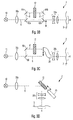
- Figures 3A , 3B, 3C and 3D schematically show embodiments of illumination systems according to the present invention.
- the xenon gas discharge lamp 10 the collimating optics 30a, the spectral filter 12 and the illumination optics 30b are schematically illustrated along an illumination beam path 6, as well as the object region 4.
- a double arrow indicated near an element indicates in any of these Figures a possible movement of this element to position the spectral filter into the illumination beam path and to remove it from the same, respectively.
- the spectral filter 12 is positioned into the illumination beam path 6 and 6' and removed from the same, respectively, in different manners.
- the illumination beam path 6 is stationary and the spectral filter 12 is displaced perpendicular to a direction of the illumination beam path 6, to position it into the same and to remove it from the same, respectively, similarly as illustrated in Figures 1 and 2 .
- a pair of mirrors 62a and 62b is translated in a direction perpendicular to the illumination beam path 6 (vertically in Figure 3B ) so that light emanating from the xenon gas discharge lamp 10 and collimated by the collimating optics 30a is guided along an illumination beam path 6' using the pair of mirrors 64a and 64b, which illumination beam path 6' is modified compared to the illumination beam path 6, wherein the spectral filter 12 is positioned in the modified illumination beam path 6'.
- a semitransparent mirror 66 and mirror 68 are provided.
- Light emanating from the xenon gas discharge lamp 10 and collimated by the collimating optics 30a is divided in two partial beams along two illumination beam paths 6 and 6', respectively, at the semitransparent mirror 66.
- Light propagating along the illumination beam path 6' is reflected at the mirror 68 to traverse the spectral filter 12.
- Figure 3D shows an embodiment of the illumination system 2 of the present invention, wherein a reflection spectral filter is used as the spectral filter 12.
- the reflection spectral filter 12 is mounted beside a mirror 70, wherein both elements are translatable in a coupled manner along a guide rail aligned in an angle of 45 ° relative to a direction of the illumination beam path 6.
- the light emanating from the xenon gas discharge lamp 10 and collimated by the collimating optics 30a either is incident onto the spectral filter 12 or the mirror 70.
- filtered light In the former case filtered light and in the latter case unfiltered light is incident onto the object region 4 for illumination.
- the displacing the spectral filter 12 and/or the illumination beam path 6 may be carried out in a coupled manner or separately and the displacing may be carried out manually or using an appropriate driving apparatus such as an electro motor.
- an appropriate driving apparatus such as an electro motor.
- a rotation may be carried out to position the spectral filter into the illumination beam path and to remove it from the same, respectively.
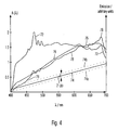
- Figure 4 illustrates a filter characteristics 74 of a spectral filter according to the embodiment of the present invention.
- the x-axis of the diagram of Figure 4 represents a wavelength of light measured in units of nanometer.
- the y-axis represents an intensity of a light emission of a xenon gas discharge lamp 72 and a halogen lamp 76 (here in unites power per area per wavelength, mW/(cm 2 *nm)) and a transmission characteristics 74 (A( ⁇ )) of a spectral filter according to an embodiment of the present invention.
- Emission spectra 72, 76 of different light sources are depicted together with a transmission characteristics 74 of a spectral filter 12 in this diagram to illustrate advantageous effects of the employment of the inventive spectral filter 12.
- the emission spectrum 72 of a xenon gas discharge lamp 10 exhibits a substantially constant course.
- An emission spectrum constant across the variable wavelength range corresponds approximately to an emission spectrum of sunlight at noon time.
- the spectrum 76 of a halogen lamp shows significantly lower intensities at wavelengths between 400 and 450 nm.
- a fraction of blue light of a halogen lamp is reduced in comparison to a fraction of blue light of a xenon gas discharge lamp and accordingly light of a halogen lamp appears comparably more reddish to an observer.
- Light having a spectrum 72 generated by a xenon gas discharge lamp 10 as well as light having a spectrum 76 generated by a halogen lamp may in an advantageous way be utilized as illumination light 60 of a surgical microscopy system. This is in particular beneficial for imaging a portion of a human eye. For imaging low scattering structures in the eye in particular light having an emission spectrum 72 is suited, whereas a particularly intensive "red reflex" is obtained by utilizing light having an emission spectrum 76.
- a filter characteristics of a spectral filter 12 according to an embodiment of the present invention is in the diagram in Figure 4 illustrated as a straight line 74. It is apparent that a transmission of the spectral filter 12 according to this embodiment of the present invention increases linearly in dependence of the wavelength in a wavelength range between about 400 and 700 nm. Such a spectral filter having substantially a linear filter characteristics is particularly simply and economically be made. An intensity of light emanating from the spectral filter having a certain wavelength may be obtained by multiplying an intensity of light having this wavelength being incident onto the spectral filter and the filter characteristics of the spectral filter taken at this wavelength.
- a spectrum of light emanating from a spectral filter in a wavelength range may be obtained by computing intensities of light having wavelengths in this wavelength range emanating from the spectral filter.
- a result of such a multiplication of the emission spectrum 72 of the xenon gas discharge lamp with the transmission characteristics 74 of the spectral filter according to an embodiment of the present invention is depicted as curve 78 in the diagram of Figure 4 .
- the curve represents thus intensity of light of a xenon gas discharge lamp filtered by the inventive spectral filter.
- the intensity of the filtered light lies above the intensity of the light of the xenon gas discharge lamp (curve 72) being incident onto the spectral filter.
- This effect may for example intentionally be achieved by utilizing a conversion filter which converts (such as by utilizing fluorescent effects) portions of light of a first wavelength range into light of a second wavelength range.
- the second wavelength range thereby may comprise higher wavelengths than the first wavelength range.
- such a filter is not utilized. The intensity of the filtered light only appears, due to missing normalizing the curves, above the intensity of the light being incident onto the spectral filter.
- a spectrum of such filtered light only slightly deviates from an emission spectrum 76 of a halogen lamp when a suitable normalizing is performed.
- a spectral filter 12 By positioning a spectral filter 12 according to the embodiments of the present invention into an illumination beam path 6 light of a xenon gas discharge lamp 10 may be generated resembling in its spectrum light of a halogen lamp.
- the filter characteristics of the spectral filter lies between two straight lines 74a and 74b, depicted as pointed straight lines and having a vertical distance of 2* ⁇ b.
- the filter characteristics does not need to have a linear course, instead it is sufficient if the filter characteristics lies between the two straight lines 74a and 74b.
- FIG. 5 shows an embodiment of the spectral filter 12 according to the present invention.
- the spectral filter 12 comprises a substrate 14 and a plurality of layers 16 of different dielectric materials, wherein the layers are mounted on the substrate.
- the layer 16a thereby comprises TiO 2
- the layer 16b comprises SiO 2
- the layer 16b comprises TiO 2 .
- the refractive index is wavelength dependent.
- the refractive index indicated in the table above is the refractive index for a wavelength of 585 nm.
- the expression "APS” in the above table is an abbreviation for "ion supported vaporisation”.
- embodiments of the present invention comprise a surgical microscopy system having an illumination system.
- the illumination system comprises a xenon gas discharge lamp and a spectral filter which is optionally positionable into an illumination beam path of the surgical microscopy system and removable from the same.
- the spectral filter substantially exhibits, in a wavelength range between 400 nm and 700 nm, a transmission increasing from about 0.12 to 1 having a rate of increase, i.e. a gradient, between 0.025/nm and 0.0035/nm, in particular 0.00293/nm.
- the illumination system is enabled to provide light having two different spectral characteristics which is advantageous in particular for imaging structures in the human eye scattering to a different degree.
Landscapes
- Health & Medical Sciences (AREA)
- Physics & Mathematics (AREA)
- Life Sciences & Earth Sciences (AREA)
- Surgery (AREA)
- General Health & Medical Sciences (AREA)
- Engineering & Computer Science (AREA)
- General Physics & Mathematics (AREA)
- Heart & Thoracic Surgery (AREA)
- Medical Informatics (AREA)
- Molecular Biology (AREA)
- Biomedical Technology (AREA)
- Animal Behavior & Ethology (AREA)
- Optics & Photonics (AREA)
- Public Health (AREA)
- Veterinary Medicine (AREA)
- Ophthalmology & Optometry (AREA)
- Biophysics (AREA)
- Chemical & Material Sciences (AREA)
- Analytical Chemistry (AREA)
- Nuclear Medicine, Radiotherapy & Molecular Imaging (AREA)
- Oral & Maxillofacial Surgery (AREA)
- Pathology (AREA)
- Microscoopes, Condenser (AREA)
Applications Claiming Priority (1)
| Application Number | Priority Date | Filing Date | Title |
|---|---|---|---|
| DE102007026044A DE102007026044B9 (de) | 2007-06-04 | 2007-06-04 | Operationsmikroskopiesystem und Abbildungsverfahren |
Publications (1)
| Publication Number | Publication Date |
|---|---|
| EP2015124A1 true EP2015124A1 (de) | 2009-01-14 |
Family
ID=39597819
Family Applications (1)
| Application Number | Title | Priority Date | Filing Date |
|---|---|---|---|
| EP08009562A Withdrawn EP2015124A1 (de) | 2007-06-04 | 2008-05-26 | Chirurgisches Mikroskopiesystem und Bildgebungsverfahren |
Country Status (3)
| Country | Link |
|---|---|
| EP (1) | EP2015124A1 (de) |
| JP (1) | JP2009006136A (de) |
| DE (1) | DE102007026044B9 (de) |
Cited By (2)
| Publication number | Priority date | Publication date | Assignee | Title |
|---|---|---|---|---|
| US9025244B2 (en) | 2009-06-17 | 2015-05-05 | Carl Zeiss Meditec Ag | Illuminating system and an optical viewing apparatus incorporating said illuminating system |
| US9829692B2 (en) | 2009-04-14 | 2017-11-28 | Carl Zeiss Meditec Ag | Optical observation unit and method for ensuring an unchanging illumination intensity when changing the color temperature of the illumination |
Families Citing this family (4)
| Publication number | Priority date | Publication date | Assignee | Title |
|---|---|---|---|---|
| WO2010055700A1 (ja) | 2008-11-14 | 2010-05-20 | 株式会社フジクラ | イッテルビウム添加光ファイバ、ファイバレーザ及びファイバアンプ |
| EP2443991B1 (de) * | 2010-10-20 | 2016-08-17 | Möller-Wedel GmbH & Co. KG | Operationsmikroskop mit Vorrichtung zur intraoperativen Refraktionsmessung |
| DE202011110431U1 (de) * | 2011-04-18 | 2014-01-07 | Leica Microsystems (Schweiz) Ag | Operationsmikroskopsystem |
| DE102013009817B4 (de) * | 2013-06-11 | 2019-10-31 | Carl Zeiss Meditec Ag | Mikroskopiesystem zur Beobachtung von Fluoreszenz in der Ophthalmologie |
Citations (2)
| Publication number | Priority date | Publication date | Assignee | Title |
|---|---|---|---|---|
| DE102004005428A1 (de) | 2003-11-28 | 2005-07-07 | Carl Zeiss | Operationsmikroskop für die Ophthalmologie |
| EP1769733A2 (de) * | 2005-09-30 | 2007-04-04 | Kabushiki Kaisha TOPCON | Augenmikroskop |
-
2007
- 2007-06-04 DE DE102007026044A patent/DE102007026044B9/de active Active
-
2008
- 2008-05-26 EP EP08009562A patent/EP2015124A1/de not_active Withdrawn
- 2008-06-04 JP JP2008147119A patent/JP2009006136A/ja not_active Withdrawn
Patent Citations (2)
| Publication number | Priority date | Publication date | Assignee | Title |
|---|---|---|---|---|
| DE102004005428A1 (de) | 2003-11-28 | 2005-07-07 | Carl Zeiss | Operationsmikroskop für die Ophthalmologie |
| EP1769733A2 (de) * | 2005-09-30 | 2007-04-04 | Kabushiki Kaisha TOPCON | Augenmikroskop |
Non-Patent Citations (1)
| Title |
|---|
| "Optische Glasfilter", 1984, SCHOTT GLASSWERKE, XP002494841 * |
Cited By (2)
| Publication number | Priority date | Publication date | Assignee | Title |
|---|---|---|---|---|
| US9829692B2 (en) | 2009-04-14 | 2017-11-28 | Carl Zeiss Meditec Ag | Optical observation unit and method for ensuring an unchanging illumination intensity when changing the color temperature of the illumination |
| US9025244B2 (en) | 2009-06-17 | 2015-05-05 | Carl Zeiss Meditec Ag | Illuminating system and an optical viewing apparatus incorporating said illuminating system |
Also Published As
| Publication number | Publication date |
|---|---|
| DE102007026044B9 (de) | 2009-09-24 |
| JP2009006136A (ja) | 2009-01-15 |
| DE102007026044B3 (de) | 2008-08-14 |
Similar Documents
| Publication | Publication Date | Title |
|---|---|---|
| US7839566B2 (en) | Surgical microscopy system and imaging method | |
| FI126159B (fi) | Tutkimusinstrumentti | |
| US9829692B2 (en) | Optical observation unit and method for ensuring an unchanging illumination intensity when changing the color temperature of the illumination | |
| US8066374B2 (en) | Optical system for a fundus camera | |
| JP5259570B2 (ja) | 照明装置ならびに観察装置 | |
| US8708493B2 (en) | Illumination device as well as observation device | |
| US5760952A (en) | Illuminating device for a surgical microscope | |
| EP2015124A1 (de) | Chirurgisches Mikroskopiesystem und Bildgebungsverfahren | |
| CN105136753B (zh) | 滤光系统、荧光观测系统和执行荧光观测的方法 | |
| US9538914B2 (en) | Microscopy system for observing fluorescence in ophthalmology | |
| US20120176769A1 (en) | Illumination device and medical-optical observation instrument | |
| WO2024148299A1 (en) | Surgical microscopes using red reflex illumination | |
| US11385447B2 (en) | Microscopes including illumination field diaphragms | |
| US20080137184A1 (en) | Illumination System for Surgical Microscope | |
| US7385757B2 (en) | Surgical microscope for ophthalmology | |
| JP2018097366A (ja) | 少なくとも1つのスペクトル選択素子を含む光学機器 | |
| RU2604958C2 (ru) | Отводимый светоделитель для микроскопа | |
| US20250347903A1 (en) | Optical observation apparatus and method for providing an optical observation apparatus with a laser protection filter | |
| RU2214152C2 (ru) | Фундус-камера | |
| US20250344947A1 (en) | Ophthalmological optical observation apparatus, method for providing an ophthalmological optical observation apparatus with a laser protection filter and fundus imaging system | |
| JPH11109250A (ja) | 干渉フィルタを有する手術用顕微鏡及び干渉フィルタ | |
| WO2020234895A1 (en) | Illumination system for surgical and other stereo microscopes | |
| JP2018050820A (ja) | 倒像検眼鏡 | |
| JP2017099719A (ja) | 細隙鏡顕微鏡 | |
| CN121878965A (zh) | 用于手术显微镜的照明系统以及手术显微镜 |
Legal Events
| Date | Code | Title | Description |
|---|---|---|---|
| PUAI | Public reference made under article 153(3) epc to a published international application that has entered the european phase |
Free format text: ORIGINAL CODE: 0009012 |
|
| PUAI | Public reference made under article 153(3) epc to a published international application that has entered the european phase |
Free format text: ORIGINAL CODE: 0009012 |
|
| AK | Designated contracting states |
Kind code of ref document: A1 Designated state(s): AT BE BG CH CY CZ DE DK EE ES FI FR GB GR HR HU IE IS IT LI LT LU LV MC MT NL NO PL PT RO SE SI SK TR |
|
| AX | Request for extension of the european patent |
Extension state: AL BA MK RS |
|
| AKX | Designation fees paid | ||
| STAA | Information on the status of an ep patent application or granted ep patent |
Free format text: STATUS: THE APPLICATION IS DEEMED TO BE WITHDRAWN |
|
| 18D | Application deemed to be withdrawn |
Effective date: 20090715 |
|
| REG | Reference to a national code |
Ref country code: DE Ref legal event code: 8566 |