EP2014941A2 - Gleichlaufgelenk mit festem Zentrum - Google Patents
Gleichlaufgelenk mit festem Zentrum Download PDFInfo
- Publication number
- EP2014941A2 EP2014941A2 EP08156589A EP08156589A EP2014941A2 EP 2014941 A2 EP2014941 A2 EP 2014941A2 EP 08156589 A EP08156589 A EP 08156589A EP 08156589 A EP08156589 A EP 08156589A EP 2014941 A2 EP2014941 A2 EP 2014941A2
- Authority
- EP
- European Patent Office
- Prior art keywords
- grooves
- axis
- clockwise
- cage
- constant velocity
- Prior art date
- Legal status (The legal status is an assumption and is not a legal conclusion. Google has not performed a legal analysis and makes no representation as to the accuracy of the status listed.)
- Granted
Links
Images




Classifications
-
- F—MECHANICAL ENGINEERING; LIGHTING; HEATING; WEAPONS; BLASTING
- F16—ENGINEERING ELEMENTS AND UNITS; GENERAL MEASURES FOR PRODUCING AND MAINTAINING EFFECTIVE FUNCTIONING OF MACHINES OR INSTALLATIONS; THERMAL INSULATION IN GENERAL
- F16D—COUPLINGS FOR TRANSMITTING ROTATION; CLUTCHES; BRAKES
- F16D3/00—Yielding couplings, i.e. with means permitting movement between the connected parts during the drive
- F16D3/16—Universal joints in which flexibility is produced by means of pivots or sliding or rolling connecting parts
- F16D3/20—Universal joints in which flexibility is produced by means of pivots or sliding or rolling connecting parts one coupling part entering a sleeve of the other coupling part and connected thereto by sliding or rolling members
- F16D3/22—Universal joints in which flexibility is produced by means of pivots or sliding or rolling connecting parts one coupling part entering a sleeve of the other coupling part and connected thereto by sliding or rolling members the rolling members being balls, rollers, or the like, guided in grooves or sockets in both coupling parts
- F16D3/223—Universal joints in which flexibility is produced by means of pivots or sliding or rolling connecting parts one coupling part entering a sleeve of the other coupling part and connected thereto by sliding or rolling members the rolling members being balls, rollers, or the like, guided in grooves or sockets in both coupling parts the rolling members being guided in grooves in both coupling parts
-
- F—MECHANICAL ENGINEERING; LIGHTING; HEATING; WEAPONS; BLASTING
- F16—ENGINEERING ELEMENTS AND UNITS; GENERAL MEASURES FOR PRODUCING AND MAINTAINING EFFECTIVE FUNCTIONING OF MACHINES OR INSTALLATIONS; THERMAL INSULATION IN GENERAL
- F16D—COUPLINGS FOR TRANSMITTING ROTATION; CLUTCHES; BRAKES
- F16D3/00—Yielding couplings, i.e. with means permitting movement between the connected parts during the drive
- F16D3/16—Universal joints in which flexibility is produced by means of pivots or sliding or rolling connecting parts
- F16D3/20—Universal joints in which flexibility is produced by means of pivots or sliding or rolling connecting parts one coupling part entering a sleeve of the other coupling part and connected thereto by sliding or rolling members
- F16D3/22—Universal joints in which flexibility is produced by means of pivots or sliding or rolling connecting parts one coupling part entering a sleeve of the other coupling part and connected thereto by sliding or rolling members the rolling members being balls, rollers, or the like, guided in grooves or sockets in both coupling parts
- F16D3/223—Universal joints in which flexibility is produced by means of pivots or sliding or rolling connecting parts one coupling part entering a sleeve of the other coupling part and connected thereto by sliding or rolling members the rolling members being balls, rollers, or the like, guided in grooves or sockets in both coupling parts the rolling members being guided in grooves in both coupling parts
- F16D2003/22303—Details of ball cages
-
- F—MECHANICAL ENGINEERING; LIGHTING; HEATING; WEAPONS; BLASTING
- F16—ENGINEERING ELEMENTS AND UNITS; GENERAL MEASURES FOR PRODUCING AND MAINTAINING EFFECTIVE FUNCTIONING OF MACHINES OR INSTALLATIONS; THERMAL INSULATION IN GENERAL
- F16D—COUPLINGS FOR TRANSMITTING ROTATION; CLUTCHES; BRAKES
- F16D3/00—Yielding couplings, i.e. with means permitting movement between the connected parts during the drive
- F16D3/16—Universal joints in which flexibility is produced by means of pivots or sliding or rolling connecting parts
- F16D3/20—Universal joints in which flexibility is produced by means of pivots or sliding or rolling connecting parts one coupling part entering a sleeve of the other coupling part and connected thereto by sliding or rolling members
- F16D3/22—Universal joints in which flexibility is produced by means of pivots or sliding or rolling connecting parts one coupling part entering a sleeve of the other coupling part and connected thereto by sliding or rolling members the rolling members being balls, rollers, or the like, guided in grooves or sockets in both coupling parts
- F16D3/223—Universal joints in which flexibility is produced by means of pivots or sliding or rolling connecting parts one coupling part entering a sleeve of the other coupling part and connected thereto by sliding or rolling members the rolling members being balls, rollers, or the like, guided in grooves or sockets in both coupling parts the rolling members being guided in grooves in both coupling parts
- F16D2003/22309—Details of grooves
-
- Y—GENERAL TAGGING OF NEW TECHNOLOGICAL DEVELOPMENTS; GENERAL TAGGING OF CROSS-SECTIONAL TECHNOLOGIES SPANNING OVER SEVERAL SECTIONS OF THE IPC; TECHNICAL SUBJECTS COVERED BY FORMER USPC CROSS-REFERENCE ART COLLECTIONS [XRACs] AND DIGESTS
- Y10—TECHNICAL SUBJECTS COVERED BY FORMER USPC
- Y10S—TECHNICAL SUBJECTS COVERED BY FORMER USPC CROSS-REFERENCE ART COLLECTIONS [XRACs] AND DIGESTS
- Y10S464/00—Rotary shafts, gudgeons, housings, and flexible couplings for rotary shafts
- Y10S464/904—Homokinetic coupling
- Y10S464/906—Torque transmitted via radially spaced balls
Definitions
- the present invention relates to a ball-type constant velocity joint, and more specifically to a fixed-center constant velocity joint kinematically defined by longitudinal grooves and helical grooves for guiding movement of balls.
- Known ball-type constant velocity joints are typically of a stroking variety and facilitate rotational movement between a driving shaft and a driven shaft.
- the ball-type joint is especially useful in applications wherein the driving and driven shafts are angled with respect to one another.
- Known joints include an inner race attached to one of the shafts and an outer race attached to the other shaft.
- the inner and outer races define grooves or channels which cooperate to form passages. Roller balls are positioned in the passages and torque is transmitted between the shafts with the roller balls.
- Known ball-type joints may include six-balls or eight-balls. Generally, six-ball joints provide greater stroke and angle capabilities than eight-ball joints. On the other hand, eight-ball joints generally can be more compact than six-ball joints. It is desirable to develop a ball-type joint having the advantage of compactness provided by eight-ball joints with the angle capabilities of six-ball joints, while at the same time improving NVH (Noise Vibration and Harshness) characteristics and mechanical efficiency. Yet further, it would be desirable to develop a self-retained and fixed-center joint (i.e. non-stroking) wherein at least a portion of the joint has the ability to hold itself together prior to full assembly in any environmental application, and when operating, a joint that prevents stroking or telescoping movement.
- NVH Noise Vibration and Harshness
- a fixed-center constant velocity joint has a race located concentrically to a rotational first axis, and a ring-shaped cage located concentrically to a rotational second axis. Both the race and the cage are centered to a common center point lying on the first and second axis regardless of the angular state of the joint.
- a spherical surface carried by the race radially opposes a spherical face carried by the cage for angular movement with respect to the center point. The surface and face are in close or contacting relationship to prevent telescoping movement with respect to the first and second axis.
- a plurality of grooves in and distributed circumferentially about the race preferably includes longitudinal, clockwise and counter-clockwise grooves that extend substantially axially and communicate laterally and in an radial direction through the spherical surface.
- a ball is located in each groove and extends through respective windows in the cage.
- the windows associated with the clockwise and counter-clockwise grooves extend circumferentially further than the windows associated with the longitudinal grooves.
- the spherical face of the cage is one of a convex and concave profile and the spherical surface is the other of the convex and concave profiles.
- the race that is fixed-center to the cage is an inner race with the spherical surface being an outer surface having a convex profile.
- the grooves cooperate with corresponding channels in an outer race such that the helical channels of the outer race cooperate with the helical grooves of the inner race to form cross groove passages. That is, clockwise grooves are associated with counter-clockwise channels and vice-versa.
- the ring-shaped cage is located radially between the inner and outer races.
- Objects, features and advantages of the present invention include a ball-type constant velocity joint that is compact in design while having large angles of magnitude, telescoping capability and is fixed-center preventing telescoping movement.
- Other advantages include a robust, light weight, design requiring little or no maintenance and in service has a long and useful life.
- Figure 1 is an exploded perspective view of a fixed-center constant velocity joint embodying the present invention
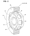
- Figure 2 is a perspective view of the fixed-center constant velocity joint with an outer race segmented to show internal detail
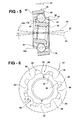
- Figure 3 is a front view of the fixed-center constant velocity joint
- Figure 4 is a cross section of the fixed-center constant velocity joint taken along line 4-4 of Figure 3 and illustrated in an axial co-extending state;
- Figure 5 is a cross section of the fixed-center constant velocity joint similar in perspective to Figure 4 except illustrated in an angled state;
- Figure 6 is a front view of an inner race of the fixed-center constant velocity joint
- Figure 7 is a plan view of a spherical outer surface of the inner race viewed along line 7-7 of Figure 6 ;
- Figure 8 is a front view of the outer race
- Figure 9 is a plan view of an inner surface of the outer race viewed along line 9-9 of Figure 8 ;
- Figure 10 is a cross section of a cage of the fixed-center constant velocity joint taken along an imaginary plane co-extending with a rotation axis of the cage;
- Figure 11 is a partial side view of the cage illustrating a long window
- Figure 12 is a partial side view of the cage illustrating a short window.
- the present invention is a self retained and fixed-center constant velocity joint 20 preferably of a ball-type.
- the joint 20 has an inner race 22 connected rigidly and disposed concentrically to an end of a first shaft (not shown) that rotates about a first axis 24.
- the inner race 22 is generally surrounded circumferentially by a cage 26 that rotates about a second axis 27, and the cage 26 is surrounded circumferentially by an outer race 28.
- the outer race 28 is connected rigidly to a second shaft (not shown) that rotates about a third axis 30.
- eight balls 29 are located radially between the inner and outer races 22, 28 and spaced circumferentially from one another with respect to axes 24, 30.
- the inner race 22 preferably has an annular forward wall 36 and an opposite annular rearward wall 38 each having a generally circular and radially outward perimeter 40.
- a circumferentially extending outward surface 44 of the inner race 22 is generally spherical and spans contiguously from and axially (with respect to axis 24) between the outward perimeters 40 of the forward and rearward walls 36, 38.
- the spherical outward surface 44 has a forward portion 46, an apex portion 48 and a rearward portion 50 that all extend circumferentially with the apex portion 48 being located axially directly between the forward and rearward portions 46, 50.
- the forward portion 46 spans axially and contiguously rearward from the forward perimeter 40, and diverges radially outward to the apex portion 48.
- the rearward portion 50 spans axially and contiguously forward from the rearward perimeter 40 of the rearward wall 38, and diverges radially outward to the apex portion 48.
- Apex portion 48 may be a continuation of the spherical shape of the outward surface 44 or may be cylindrical in shape.
- a cross section of inner race 22 taken through an imaginary plane co-extending with axis 24 illustrates a convex profile of the outward surface 44. That is, the forward and rearward portions 46 have a circular profile with the apex portion 48 continuing the circular profile or in the alternative with the apex portion having a flat or plateau-like profile (i.e. if cylindrical).
- relationships between the races 22, 28 and cage 26 are in-part expressed in axial diameters and spherical diameters.
- An axial diameter is that distance along a line that lies in an imaginary plane orientated perpendicular to a respective rotation axis.
- a spherical diameter is that distance along a line that extends through a common center point 110 of both the inner race 22 and the cage 26.
- the perimeters 40 of the inner race 22 have axial diameters 42.
- the generally circular apex portion 48 thus has an axial diameter 52 that is greater than the diameter 42 of the forward and rearward perimeters 40 (as best shown in Figure 4 ).
- the axial diameter 52 is equivalent in distance to a spherical diameter 53 of the forward and rearward portions 46, 50 of the outer surface 44.
- the axial diameter 42 of the perimeter 40 is the minimum axial diameter of the outward surface 44 and the diameter 52 of the apex portion 48 is the maximum axial diameter of the surface 44.
- the inner race 22 preferably has eight or a series of grooves 54 that longitudinally extend axially with respect to axis 24 and communicate radially outward through the outward surface 44.
- each one of the series of grooves 54 also communicate through the forward and rearward perimeters 40, thus generally making the perimeters circumferentially discontinuous.
- Each groove of the series of grooves 54 is spaced circumferentially from the next adjacent one of the series of grooves 54.
- the series of grooves 54 have four longitudinal grooves 56 that extend parallel to axis 24, two helical clockwise grooves 58 that slightly spiral or angle in a clockwise direction as the grooves 58 longitudinally extend axially rearward (i.e.
- Each longitudinal groove 56 is circumferentially adjacent to a clockwise groove 58 on one side and a counter-clockwise groove 60 on the opposite side. Moreover, each helical or angled groove 58, 60 is located circumferentially between two longitudinal grooves 56 of the series of grooves 54. The longitudinal grooves 56 are preferably spaced angularly by about ninety degrees from one another. As best illustrated in Figure 7 , each angled groove 58, 60 is inclined with respect to the adjacent longitudinal grooves 56 by respective positive and negative angles represented by arrows 62, 64. The absolute magnitude of the angles or arrows 62, 64 are about or preferably are equal to one another.
- the outer race 28 has an annular forward wall 66 and an opposite annular rearward wall 68, both disposed substantially perpendicular to axis 30.
- a circumferentially extending inner surface 70 of the outer race 28 spans laterally in an axial direction (with respect to axis 30) between the forward and rearward walls 66, 68.
- the outer race 28 preferably has eight channels or grooves 72 that longitudinally extend axially with respect to axis 30 and communicate laterally inward (i.e. radially inward with respect to axis 30) through the inner surface 70.
- Each channel of the series of channels 72 is associated with a respective one of the series of grooves 54, and is thus spaced circumferentially from the next adjacent one of the series of channels 72.
- the series of channels 72 have four longitudinal channels 74 that extend parallel to axis 30, two helical clockwise channels 76 that slightly spiral or angle in a clockwise direction as the channels 76 longitudinally extend axially rearward (i.e. rearward direction/arrow 34), and two helical counter-clockwise channels 78 that slightly spiral or angle in a counter-clockwise direction as the channels 78 longitudinally extend axially rearward.
- the spiraling affect of the channels 76, 78 may not be truly helical in shape, and instead may be simply angled with respect to the longitudinal grooves 58 and as best illustrated in Figure 9 .
- Each longitudinal channel 74 is circumferentially adjacent to a clockwise channel 76 on one side and a counter-clockwise channel 78 on the opposite side. Moreover, each helical or angled channel 76, 78 is located circumferentially between two longitudinal channels 74 of the series of channels 72.
- the longitudinal channels 74 are preferably spaced angularly by about ninety degrees from one another.
- each angled channel 76, 78 is inclined with respect to the adjacent longitudinal channels 74 by respective positive and negative angles 80, 82.
- absolute magnitude of the angles 80, 82 are equal to one another and equal to the absolute magnitude of angles 62, 64.
- each one of the longitudinal grooves 56 of the inner race 22 is circumferentially aligned to a respective one of the longitudinal channels 74 of the outer race 28, thereby forming a passage for travel of a respective one of the balls 29.
- each one of the clockwise grooves 58 is aligned circumferentially to a respective one of the counter-clockwise channels 78
- each one of the counter-clockwise grooves 60 is aligned circumferentially to a respective one of the clockwise channels 76 all respectively forming passages for travel of respective balls 29.
- the inclined or cross groove passages create a constant velocity plane when the joint 20 is angled.
- the degree of incline of clockwise and counter-clockwise grooves can be smaller than that of a standard 6-ball joint design.
- the straight or longitudinal passages and cross grooved passages cooperate to allow a greater stroke than a joint that has inclined grooves.
- reduction of the helix angle of the helical grooves decreases the contact stresses in the grooves/channels and the forces transmitted to the cage 26 disposed between the inner and outer races 22, 28.
- Cross groove passages are discussed in greater detail in U.S. Patent No. 6,468,164 , which is incorporated herein by reference.
- the cage 26 of the joint 20 preferably has four short windows 86 and four long windows 88. All of the windows 86, 88 are elongated circumferentially with respect to axis 27 and communicate radially through the cage 26. Each one of the short windows 86 is associated with (i.e. adjacent to) a respective one of the longitudinal grooves 56 and each one of the long windows 88 is associated with a respective one of the helical or angled grooves 58, 60 in the inner race 22.
- the width of the short and long windows 86, 88 are about the same, and are slightly greater than the diameter of the balls 29 for minimizing internal friction of the joint 20.
- the cage 26 may generally lock or trap the balls 29 to the inner race 22.
- This alternative embodiment would preferably have a frictionless or friction reducing interface between the balls 29 and the cage 26 for smooth operation of the joint 20.
- the short windows 86 are defined by a continuous wall 90 having opposing side segments 92 and flanking or opposing end segments 94.
- the side segments 92 are substantially parallel to one another, extend circumferentially with respect to axis 27, and define the width of the window 86.
- the opposing end segments 94 preferably have a radius of curvature 95 equal to about half the width of window 86.
- the long windows 88 are defined by a continuous wall 96 having opposing side segments 98 and flanking or opposing end segments 100.
- the side segments 98 are substantially parallel to one another, extend circumferentially with respect to axis 27, and define the width of the window 88.
- the opposing end segments 100 preferably have a radius of curvature 101 that even when doubled is substantially less than the width of window 88.
- the width of window 88 is about equal to four time the radius of curvature 101 of the end segments 100.
- the large radius of curvature of the end segments 94 of continuous wall 90 of short windows 86 provides structural integrity and strength to the cage 26.
- the cage 26 is generally ring-shaped having a spherical inner face 102 that extends circumferentially and faces radially inward.
- An opposite outer face 104 of the cage 26 faces radially outward and is preferably substantially spherical.
- the continuous walls 90, 96 defining the windows span laterally between and form contiguously into the inner and outer faces 102, 104.
- the inner and outer faces 102, 104 preferably have respective spherical diameters 106, 108 that both cross through the center point 110, common to both the inner race 22 and the cage 26 (as best shown in Figure 10 ).
- the inner face 102 thus has a concave profile and the outer face 104 has a convex profile when a cross section is taken along an imaginary plane that co-extends with the axis 27.
- the inner face 102 of the cage 26 spans laterally (i.e. axially with respect to axis 27) between forward and rearward rims 112, 114 having substantially equal axial diameters 116 (see Figures 4 and 5 ) and the spherical diameter 106 (i.e. extending from rim 112 and through center point 110 to rim 114).
- the axial diameter 116 of the rims 112, 114 is less than the axial diameter 52 of the apex portion 48 of the outer surface 44 of the inner race 22.
- the spherical diameter 53 of the outer surface 44 of the inner race 22 is about equal to or only slightly less than the spherical diameter 106 of the inner face 102 of the cage 26.
- the inner race 22 and cage 26 are made of or coated with a friction reducing material.
- the joint 20 moves from a linear state 118, as best shown in Figure 4 , to an angled state 124, as best shown in Figure 5 .
- the joint 20 is in the linear state 118, preferably all three axes 24, 27, 30 co-extend to one-another, and thus do not intersect. That is, the inner race 22, the cage 26 and the outer race 28 are substantially concentric to one-another and with respect to the common center point 110.
- the axis 24 of the inner race 22 and the axis 27 of the cage 26 and the axis 30 of the outer race 28 will intersect at center point 110.
- axis 24 of the inner race 22 is angled with respect to axis 27 of the cage 26 by a negative angular displacement represented by arrow 134 and the axis 30 of the outer race 28 is angled with respect to axis 27 by a positive angular displacement represented by arrow 136.
- the absolute magnitude of angular displacements 134, 136 are about or preferably equal to one another.
Landscapes
- Engineering & Computer Science (AREA)
- General Engineering & Computer Science (AREA)
- Mechanical Engineering (AREA)
- Rolling Contact Bearings (AREA)
- Pivots And Pivotal Connections (AREA)
- Support Of The Bearing (AREA)
Applications Claiming Priority (1)
| Application Number | Priority Date | Filing Date | Title |
|---|---|---|---|
| US11/827,127 US7717793B2 (en) | 2007-07-10 | 2007-07-10 | Fixed-center constant velocity joint |
Publications (3)
| Publication Number | Publication Date |
|---|---|
| EP2014941A2 true EP2014941A2 (de) | 2009-01-14 |
| EP2014941A3 EP2014941A3 (de) | 2013-05-01 |
| EP2014941B1 EP2014941B1 (de) | 2014-07-09 |
Family
ID=39830370
Family Applications (1)
| Application Number | Title | Priority Date | Filing Date |
|---|---|---|---|
| EP08156589.7A Active EP2014941B1 (de) | 2007-07-10 | 2008-05-20 | Gleichlaufgelenk mit festem Zentrum |
Country Status (2)
| Country | Link |
|---|---|
| US (1) | US7717793B2 (de) |
| EP (1) | EP2014941B1 (de) |
Cited By (2)
| Publication number | Priority date | Publication date | Assignee | Title |
|---|---|---|---|---|
| KR101345903B1 (ko) | 2011-11-21 | 2013-12-30 | 현대위아 주식회사 | 차량용 슬라이드식 볼타입 등속조인트 |
| CN107401523A (zh) * | 2017-08-30 | 2017-11-28 | 安徽莱恩电泵有限公司 | 一种防逆反中开泵 |
Families Citing this family (4)
| Publication number | Priority date | Publication date | Assignee | Title |
|---|---|---|---|---|
| US8070611B2 (en) * | 2009-05-13 | 2011-12-06 | Gkn Driveline North America, Inc. | Plunging cross-track constant velocity joint |
| US8382600B2 (en) * | 2009-09-18 | 2013-02-26 | Hyundai Wia Corporation | Cross groove type constant velocity joint with composite groove patterns |
| JP5823127B2 (ja) * | 2011-01-06 | 2015-11-25 | Ntn株式会社 | 固定式等速自在継手 |
| KR101994661B1 (ko) * | 2019-01-02 | 2019-07-01 | 서한산업(주) | 등속조인트용 케이지 및 그 케이지 및 슬리브 일체형 내륜을 갖는 등속조인트 |
Citations (1)
| Publication number | Priority date | Publication date | Assignee | Title |
|---|---|---|---|---|
| US6468164B2 (en) | 2000-02-16 | 2002-10-22 | Delphi Technologies, Inc. | Constant velocity joint having fixed center and crossed grooves |
Family Cites Families (16)
| Publication number | Priority date | Publication date | Assignee | Title |
|---|---|---|---|---|
| US1916442A (en) * | 1929-08-21 | 1933-07-04 | Alfred H Rzeppa | Universal joint |
| US2322570A (en) * | 1941-12-26 | 1943-06-22 | Adiel Y Dodge | Universal joint |
| DE1170720B (de) * | 1960-06-25 | 1964-05-21 | Rheinmetall Gmbh | Homokinetisches Universalgelenk |
| GB1042721A (en) * | 1962-03-30 | 1966-09-14 | Loehr & Bromkamp Gmbh | Constant velocity ratio joints |
| US3447341A (en) * | 1966-12-19 | 1969-06-03 | Dana Corp | Ball cage for ball type constant velocity joint |
| DD122842A5 (de) * | 1975-05-22 | 1976-11-05 | ||
| DE3102871C2 (de) | 1981-01-29 | 1984-01-12 | Löhr & Bromkamp GmbH, 6050 Offenbach | "Gleichlaufdrehgelenk" |
| DE3818730C1 (en) | 1988-06-01 | 1989-07-27 | Loehr & Bromkamp Gmbh, 6050 Offenbach, De | Telescopic constant-velocity joint |
| DE3939531C1 (de) * | 1989-11-30 | 1991-06-06 | Loehr & Bromkamp Gmbh, 6050 Offenbach, De | |
| DE4440285C1 (de) * | 1994-11-11 | 1996-04-25 | Loehr & Bromkamp Gmbh | Kugelgleichlaufdrehgelenk |
| DE19507859C2 (de) * | 1995-03-08 | 1998-04-16 | Loehr & Bromkamp Gmbh | Gleichlaufdrehgelenk in VL-Bauart mit gekrümmtem Bahnverlauf |
| US5687777A (en) * | 1996-03-11 | 1997-11-18 | Ohmeda Inc. | Anesthetic agent filler valve |
| US5893801A (en) * | 1996-11-04 | 1999-04-13 | Ford Motor Company | Segmented cross groove plunging constant velocity joint |
| DE19704761C2 (de) * | 1997-02-08 | 1999-02-04 | Gkn Automotive Ag | Kugelgleichlaufdrehgelenk |
| US6736729B2 (en) * | 2002-07-03 | 2004-05-18 | Gkn Automotive, Inc. | Constant velocity joint and method of making same |
| US7347786B2 (en) * | 2003-12-08 | 2008-03-25 | Delphi Technologies, Inc. | Cross-straight groove joint |
-
2007
- 2007-07-10 US US11/827,127 patent/US7717793B2/en active Active
-
2008
- 2008-05-20 EP EP08156589.7A patent/EP2014941B1/de active Active
Patent Citations (1)
| Publication number | Priority date | Publication date | Assignee | Title |
|---|---|---|---|---|
| US6468164B2 (en) | 2000-02-16 | 2002-10-22 | Delphi Technologies, Inc. | Constant velocity joint having fixed center and crossed grooves |
Cited By (3)
| Publication number | Priority date | Publication date | Assignee | Title |
|---|---|---|---|---|
| KR101345903B1 (ko) | 2011-11-21 | 2013-12-30 | 현대위아 주식회사 | 차량용 슬라이드식 볼타입 등속조인트 |
| CN107401523A (zh) * | 2017-08-30 | 2017-11-28 | 安徽莱恩电泵有限公司 | 一种防逆反中开泵 |
| CN107401523B (zh) * | 2017-08-30 | 2023-03-21 | 安徽莱恩电泵有限公司 | 一种防逆反中开泵 |
Also Published As
| Publication number | Publication date |
|---|---|
| US20090017922A1 (en) | 2009-01-15 |
| EP2014941B1 (de) | 2014-07-09 |
| EP2014941A3 (de) | 2013-05-01 |
| US7717793B2 (en) | 2010-05-18 |
Similar Documents
| Publication | Publication Date | Title |
|---|---|---|
| EP1264114B1 (de) | Gleichlaufgelenk mit feststehendem zentrum und sich kreuzenden rillen | |
| EP2014941B1 (de) | Gleichlaufgelenk mit festem Zentrum | |
| EP1413787B1 (de) | Gleichlauftripodegelenk | |
| US6902487B2 (en) | Longitudinal displacement unit with braking rollers | |
| US5242329A (en) | Constant velocity joint having alternating grooves | |
| CN101711315B (zh) | 具有低伸缩力的等速伸缩球型接头 | |
| US5290203A (en) | Constant velocity universal joint having high stress resistance | |
| EP2014942B1 (de) | Selbsthaltendes Gleichlaufgelenk | |
| US7347786B2 (en) | Cross-straight groove joint | |
| US7632190B2 (en) | Constant velocity joint | |
| US20020028711A1 (en) | Tripod type constant velocity universal joint | |
| US20120149478A1 (en) | Constant Velocity Joint of Tripod Type | |
| CN101268294A (zh) | 滑动式等速万向接头 | |
| AU644806B2 (en) | Undercut free constant velocity joint | |
| JP4109425B2 (ja) | 等速ジョイント | |
| JP2005201371A (ja) | 等速ジョイント | |
| KR20050045834A (ko) | 마찰감소 웨브 위치결정구를 가진 등속 죠인트 | |
| US6692364B2 (en) | Constant velocity joint | |
| US11781599B2 (en) | Constant velocity joint | |
| US20070049380A1 (en) | Tripod type constant velocity universal joint | |
| US20250361913A1 (en) | Tripod joint | |
| JP2594747Y2 (ja) | 自在継手用軸受カップ | |
| WO2025192043A1 (ja) | 摺動式等速自在継手 | |
| KR20240084744A (ko) | 트라이포드형 등속 조인트 | |
| JP2024090753A (ja) | トリポード型等速自在継手 |
Legal Events
| Date | Code | Title | Description |
|---|---|---|---|
| PUAI | Public reference made under article 153(3) epc to a published international application that has entered the european phase |
Free format text: ORIGINAL CODE: 0009012 |
|
| AK | Designated contracting states |
Kind code of ref document: A2 Designated state(s): AT BE BG CH CY CZ DE DK EE ES FI FR GB GR HR HU IE IS IT LI LT LU LV MC MT NL NO PL PT RO SE SI SK TR |
|
| AX | Request for extension of the european patent |
Extension state: AL BA MK RS |
|
| RAP1 | Party data changed (applicant data changed or rights of an application transferred) |
Owner name: GM GLOBAL TECHNOLOGY OPERATIONS, INC. |
|
| RAP1 | Party data changed (applicant data changed or rights of an application transferred) |
Owner name: GM GLOBAL TECHNOLOGY OPERATIONS LLC |
|
| RAP1 | Party data changed (applicant data changed or rights of an application transferred) |
Owner name: GM GLOBAL TECHNOLOGY OPERATIONS LLC Owner name: STEERING SOLUTIONS IP HOLDING CORPORATION |
|
| PUAL | Search report despatched |
Free format text: ORIGINAL CODE: 0009013 |
|
| AK | Designated contracting states |
Kind code of ref document: A3 Designated state(s): AT BE BG CH CY CZ DE DK EE ES FI FR GB GR HR HU IE IS IT LI LT LU LV MC MT NL NO PL PT RO SE SI SK TR |
|
| AX | Request for extension of the european patent |
Extension state: AL BA MK RS |
|
| RIC1 | Information provided on ipc code assigned before grant |
Ipc: F16D 3/223 20110101AFI20130325BHEP |
|
| 17P | Request for examination filed |
Effective date: 20131104 |
|
| RBV | Designated contracting states (corrected) |
Designated state(s): AT BE BG CH CY CZ DE DK EE ES FI FR GB GR HR HU IE IS IT LI LT LU LV MC MT NL NO PL PT RO SE SI SK TR |
|
| AKX | Designation fees paid |
Designated state(s): AT BE BG CH CY CZ DE DK EE ES FI FR GB GR HR HU IE IS IT LI LT LU LV MC MT NL NO PL PT RO SE SI SK TR |
|
| GRAP | Despatch of communication of intention to grant a patent |
Free format text: ORIGINAL CODE: EPIDOSNIGR1 |
|
| INTG | Intention to grant announced |
Effective date: 20140109 |
|
| GRAS | Grant fee paid |
Free format text: ORIGINAL CODE: EPIDOSNIGR3 |
|
| GRAA | (expected) grant |
Free format text: ORIGINAL CODE: 0009210 |
|
| AK | Designated contracting states |
Kind code of ref document: B1 Designated state(s): AT BE BG CH CY CZ DE DK EE ES FI FR GB GR HR HU IE IS IT LI LT LU LV MC MT NL NO PL PT RO SE SI SK TR |
|
| REG | Reference to a national code |
Ref country code: GB Ref legal event code: FG4D |
|
| REG | Reference to a national code |
Ref country code: AT Ref legal event code: REF Ref document number: 676691 Country of ref document: AT Kind code of ref document: T Effective date: 20140715 Ref country code: CH Ref legal event code: EP |
|
| REG | Reference to a national code |
Ref country code: IE Ref legal event code: FG4D |
|
| REG | Reference to a national code |
Ref country code: DE Ref legal event code: R096 Ref document number: 602008033174 Country of ref document: DE Effective date: 20140814 |
|
| REG | Reference to a national code |
Ref country code: AT Ref legal event code: MK05 Ref document number: 676691 Country of ref document: AT Kind code of ref document: T Effective date: 20140709 |
|
| REG | Reference to a national code |
Ref country code: NL Ref legal event code: VDEP Effective date: 20140709 |
|
| REG | Reference to a national code |
Ref country code: LT Ref legal event code: MG4D |
|
| PG25 | Lapsed in a contracting state [announced via postgrant information from national office to epo] |
Ref country code: LT Free format text: LAPSE BECAUSE OF FAILURE TO SUBMIT A TRANSLATION OF THE DESCRIPTION OR TO PAY THE FEE WITHIN THE PRESCRIBED TIME-LIMIT Effective date: 20140709 Ref country code: BG Free format text: LAPSE BECAUSE OF FAILURE TO SUBMIT A TRANSLATION OF THE DESCRIPTION OR TO PAY THE FEE WITHIN THE PRESCRIBED TIME-LIMIT Effective date: 20141009 Ref country code: PT Free format text: LAPSE BECAUSE OF FAILURE TO SUBMIT A TRANSLATION OF THE DESCRIPTION OR TO PAY THE FEE WITHIN THE PRESCRIBED TIME-LIMIT Effective date: 20141110 Ref country code: FI Free format text: LAPSE BECAUSE OF FAILURE TO SUBMIT A TRANSLATION OF THE DESCRIPTION OR TO PAY THE FEE WITHIN THE PRESCRIBED TIME-LIMIT Effective date: 20140709 Ref country code: NO Free format text: LAPSE BECAUSE OF FAILURE TO SUBMIT A TRANSLATION OF THE DESCRIPTION OR TO PAY THE FEE WITHIN THE PRESCRIBED TIME-LIMIT Effective date: 20141009 Ref country code: ES Free format text: LAPSE BECAUSE OF FAILURE TO SUBMIT A TRANSLATION OF THE DESCRIPTION OR TO PAY THE FEE WITHIN THE PRESCRIBED TIME-LIMIT Effective date: 20140709 Ref country code: GR Free format text: LAPSE BECAUSE OF FAILURE TO SUBMIT A TRANSLATION OF THE DESCRIPTION OR TO PAY THE FEE WITHIN THE PRESCRIBED TIME-LIMIT Effective date: 20141010 Ref country code: SE Free format text: LAPSE BECAUSE OF FAILURE TO SUBMIT A TRANSLATION OF THE DESCRIPTION OR TO PAY THE FEE WITHIN THE PRESCRIBED TIME-LIMIT Effective date: 20140709 |
|
| PG25 | Lapsed in a contracting state [announced via postgrant information from national office to epo] |
Ref country code: PL Free format text: LAPSE BECAUSE OF FAILURE TO SUBMIT A TRANSLATION OF THE DESCRIPTION OR TO PAY THE FEE WITHIN THE PRESCRIBED TIME-LIMIT Effective date: 20140709 Ref country code: CY Free format text: LAPSE BECAUSE OF FAILURE TO SUBMIT A TRANSLATION OF THE DESCRIPTION OR TO PAY THE FEE WITHIN THE PRESCRIBED TIME-LIMIT Effective date: 20140709 Ref country code: IS Free format text: LAPSE BECAUSE OF FAILURE TO SUBMIT A TRANSLATION OF THE DESCRIPTION OR TO PAY THE FEE WITHIN THE PRESCRIBED TIME-LIMIT Effective date: 20141109 Ref country code: NL Free format text: LAPSE BECAUSE OF FAILURE TO SUBMIT A TRANSLATION OF THE DESCRIPTION OR TO PAY THE FEE WITHIN THE PRESCRIBED TIME-LIMIT Effective date: 20140709 Ref country code: HR Free format text: LAPSE BECAUSE OF FAILURE TO SUBMIT A TRANSLATION OF THE DESCRIPTION OR TO PAY THE FEE WITHIN THE PRESCRIBED TIME-LIMIT Effective date: 20140709 Ref country code: AT Free format text: LAPSE BECAUSE OF FAILURE TO SUBMIT A TRANSLATION OF THE DESCRIPTION OR TO PAY THE FEE WITHIN THE PRESCRIBED TIME-LIMIT Effective date: 20140709 Ref country code: LV Free format text: LAPSE BECAUSE OF FAILURE TO SUBMIT A TRANSLATION OF THE DESCRIPTION OR TO PAY THE FEE WITHIN THE PRESCRIBED TIME-LIMIT Effective date: 20140709 |
|
| REG | Reference to a national code |
Ref country code: DE Ref legal event code: R097 Ref document number: 602008033174 Country of ref document: DE |
|
| PG25 | Lapsed in a contracting state [announced via postgrant information from national office to epo] |
Ref country code: RO Free format text: LAPSE BECAUSE OF FAILURE TO SUBMIT A TRANSLATION OF THE DESCRIPTION OR TO PAY THE FEE WITHIN THE PRESCRIBED TIME-LIMIT Effective date: 20140709 Ref country code: DK Free format text: LAPSE BECAUSE OF FAILURE TO SUBMIT A TRANSLATION OF THE DESCRIPTION OR TO PAY THE FEE WITHIN THE PRESCRIBED TIME-LIMIT Effective date: 20140709 Ref country code: EE Free format text: LAPSE BECAUSE OF FAILURE TO SUBMIT A TRANSLATION OF THE DESCRIPTION OR TO PAY THE FEE WITHIN THE PRESCRIBED TIME-LIMIT Effective date: 20140709 Ref country code: IT Free format text: LAPSE BECAUSE OF FAILURE TO SUBMIT A TRANSLATION OF THE DESCRIPTION OR TO PAY THE FEE WITHIN THE PRESCRIBED TIME-LIMIT Effective date: 20140709 Ref country code: SK Free format text: LAPSE BECAUSE OF FAILURE TO SUBMIT A TRANSLATION OF THE DESCRIPTION OR TO PAY THE FEE WITHIN THE PRESCRIBED TIME-LIMIT Effective date: 20140709 Ref country code: CZ Free format text: LAPSE BECAUSE OF FAILURE TO SUBMIT A TRANSLATION OF THE DESCRIPTION OR TO PAY THE FEE WITHIN THE PRESCRIBED TIME-LIMIT Effective date: 20140709 |
|
| PLBE | No opposition filed within time limit |
Free format text: ORIGINAL CODE: 0009261 |
|
| STAA | Information on the status of an ep patent application or granted ep patent |
Free format text: STATUS: NO OPPOSITION FILED WITHIN TIME LIMIT |
|
| 26N | No opposition filed |
Effective date: 20150410 |
|
| PG25 | Lapsed in a contracting state [announced via postgrant information from national office to epo] |
Ref country code: SI Free format text: LAPSE BECAUSE OF FAILURE TO SUBMIT A TRANSLATION OF THE DESCRIPTION OR TO PAY THE FEE WITHIN THE PRESCRIBED TIME-LIMIT Effective date: 20140709 |
|
| REG | Reference to a national code |
Ref country code: CH Ref legal event code: PL |
|
| PG25 | Lapsed in a contracting state [announced via postgrant information from national office to epo] |
Ref country code: LI Free format text: LAPSE BECAUSE OF NON-PAYMENT OF DUE FEES Effective date: 20150531 Ref country code: LU Free format text: LAPSE BECAUSE OF FAILURE TO SUBMIT A TRANSLATION OF THE DESCRIPTION OR TO PAY THE FEE WITHIN THE PRESCRIBED TIME-LIMIT Effective date: 20150520 Ref country code: CH Free format text: LAPSE BECAUSE OF NON-PAYMENT OF DUE FEES Effective date: 20150531 Ref country code: MC Free format text: LAPSE BECAUSE OF FAILURE TO SUBMIT A TRANSLATION OF THE DESCRIPTION OR TO PAY THE FEE WITHIN THE PRESCRIBED TIME-LIMIT Effective date: 20140709 |
|
| REG | Reference to a national code |
Ref country code: IE Ref legal event code: MM4A |
|
| REG | Reference to a national code |
Ref country code: FR Ref legal event code: ST Effective date: 20160129 |
|
| PG25 | Lapsed in a contracting state [announced via postgrant information from national office to epo] |
Ref country code: IE Free format text: LAPSE BECAUSE OF NON-PAYMENT OF DUE FEES Effective date: 20150520 |
|
| PG25 | Lapsed in a contracting state [announced via postgrant information from national office to epo] |
Ref country code: FR Free format text: LAPSE BECAUSE OF NON-PAYMENT OF DUE FEES Effective date: 20150601 |
|
| PG25 | Lapsed in a contracting state [announced via postgrant information from national office to epo] |
Ref country code: BE Free format text: LAPSE BECAUSE OF FAILURE TO SUBMIT A TRANSLATION OF THE DESCRIPTION OR TO PAY THE FEE WITHIN THE PRESCRIBED TIME-LIMIT Effective date: 20140709 |
|
| PGFP | Annual fee paid to national office [announced via postgrant information from national office to epo] |
Ref country code: GB Payment date: 20160527 Year of fee payment: 9 |
|
| PG25 | Lapsed in a contracting state [announced via postgrant information from national office to epo] |
Ref country code: MT Free format text: LAPSE BECAUSE OF FAILURE TO SUBMIT A TRANSLATION OF THE DESCRIPTION OR TO PAY THE FEE WITHIN THE PRESCRIBED TIME-LIMIT Effective date: 20140709 |
|
| PG25 | Lapsed in a contracting state [announced via postgrant information from national office to epo] |
Ref country code: HU Free format text: LAPSE BECAUSE OF FAILURE TO SUBMIT A TRANSLATION OF THE DESCRIPTION OR TO PAY THE FEE WITHIN THE PRESCRIBED TIME-LIMIT; INVALID AB INITIO Effective date: 20080520 |
|
| PG25 | Lapsed in a contracting state [announced via postgrant information from national office to epo] |
Ref country code: TR Free format text: LAPSE BECAUSE OF FAILURE TO SUBMIT A TRANSLATION OF THE DESCRIPTION OR TO PAY THE FEE WITHIN THE PRESCRIBED TIME-LIMIT Effective date: 20140709 |
|
| GBPC | Gb: european patent ceased through non-payment of renewal fee |
Effective date: 20170520 |
|
| PG25 | Lapsed in a contracting state [announced via postgrant information from national office to epo] |
Ref country code: GB Free format text: LAPSE BECAUSE OF NON-PAYMENT OF DUE FEES Effective date: 20170520 |
|
| PGFP | Annual fee paid to national office [announced via postgrant information from national office to epo] |
Ref country code: DE Payment date: 20250529 Year of fee payment: 18 |