EP2014824A1 - Reinforcing cord, method for producing the same, and product using the reinforcing cord - Google Patents
Reinforcing cord, method for producing the same, and product using the reinforcing cord Download PDFInfo
- Publication number
- EP2014824A1 EP2014824A1 EP07742672A EP07742672A EP2014824A1 EP 2014824 A1 EP2014824 A1 EP 2014824A1 EP 07742672 A EP07742672 A EP 07742672A EP 07742672 A EP07742672 A EP 07742672A EP 2014824 A1 EP2014824 A1 EP 2014824A1
- Authority
- EP
- European Patent Office
- Prior art keywords
- coating layer
- reinforcing
- reinforcing cord
- latex
- rubber
- Prior art date
- Legal status (The legal status is an assumption and is not a legal conclusion. Google has not performed a legal analysis and makes no representation as to the accuracy of the status listed.)
- Granted
Links
Images

Classifications
-
- D—TEXTILES; PAPER
- D02—YARNS; MECHANICAL FINISHING OF YARNS OR ROPES; WARPING OR BEAMING
- D02G—CRIMPING OR CURLING FIBRES, FILAMENTS, THREADS, OR YARNS; YARNS OR THREADS
- D02G3/00—Yarns or threads, e.g. fancy yarns; Processes or apparatus for the production thereof, not otherwise provided for
- D02G3/22—Yarns or threads characterised by constructional features, e.g. blending, filament/fibre
- D02G3/40—Yarns in which fibres are united by adhesives; Impregnated yarns or threads
- D02G3/404—Yarns or threads coated with polymeric solutions
-
- B—PERFORMING OPERATIONS; TRANSPORTING
- B29—WORKING OF PLASTICS; WORKING OF SUBSTANCES IN A PLASTIC STATE IN GENERAL
- B29B—PREPARATION OR PRETREATMENT OF THE MATERIAL TO BE SHAPED; MAKING GRANULES OR PREFORMS; RECOVERY OF PLASTICS OR OTHER CONSTITUENTS OF WASTE MATERIAL CONTAINING PLASTICS
- B29B15/00—Pretreatment of the material to be shaped, not covered by groups B29B7/00 - B29B13/00
- B29B15/08—Pretreatment of the material to be shaped, not covered by groups B29B7/00 - B29B13/00 of reinforcements or fillers
- B29B15/10—Coating or impregnating independently of the moulding or shaping step
- B29B15/12—Coating or impregnating independently of the moulding or shaping step of reinforcements of indefinite length
- B29B15/122—Coating or impregnating independently of the moulding or shaping step of reinforcements of indefinite length with a matrix in liquid form, e.g. as melt, solution or latex
-
- B—PERFORMING OPERATIONS; TRANSPORTING
- B29—WORKING OF PLASTICS; WORKING OF SUBSTANCES IN A PLASTIC STATE IN GENERAL
- B29C—SHAPING OR JOINING OF PLASTICS; SHAPING OF MATERIAL IN A PLASTIC STATE, NOT OTHERWISE PROVIDED FOR; AFTER-TREATMENT OF THE SHAPED PRODUCTS, e.g. REPAIRING
- B29C48/00—Extrusion moulding, i.e. expressing the moulding material through a die or nozzle which imparts the desired form; Apparatus therefor
- B29C48/03—Extrusion moulding, i.e. expressing the moulding material through a die or nozzle which imparts the desired form; Apparatus therefor characterised by the shape of the extruded material at extrusion
- B29C48/05—Filamentary, e.g. strands
-
- B—PERFORMING OPERATIONS; TRANSPORTING
- B29—WORKING OF PLASTICS; WORKING OF SUBSTANCES IN A PLASTIC STATE IN GENERAL
- B29C—SHAPING OR JOINING OF PLASTICS; SHAPING OF MATERIAL IN A PLASTIC STATE, NOT OTHERWISE PROVIDED FOR; AFTER-TREATMENT OF THE SHAPED PRODUCTS, e.g. REPAIRING
- B29C48/00—Extrusion moulding, i.e. expressing the moulding material through a die or nozzle which imparts the desired form; Apparatus therefor
- B29C48/03—Extrusion moulding, i.e. expressing the moulding material through a die or nozzle which imparts the desired form; Apparatus therefor characterised by the shape of the extruded material at extrusion
- B29C48/06—Rod-shaped
-
- B—PERFORMING OPERATIONS; TRANSPORTING
- B29—WORKING OF PLASTICS; WORKING OF SUBSTANCES IN A PLASTIC STATE IN GENERAL
- B29C—SHAPING OR JOINING OF PLASTICS; SHAPING OF MATERIAL IN A PLASTIC STATE, NOT OTHERWISE PROVIDED FOR; AFTER-TREATMENT OF THE SHAPED PRODUCTS, e.g. REPAIRING
- B29C48/00—Extrusion moulding, i.e. expressing the moulding material through a die or nozzle which imparts the desired form; Apparatus therefor
- B29C48/15—Extrusion moulding, i.e. expressing the moulding material through a die or nozzle which imparts the desired form; Apparatus therefor incorporating preformed parts or layers, e.g. extrusion moulding around inserts
- B29C48/154—Coating solid articles, i.e. non-hollow articles
-
- B—PERFORMING OPERATIONS; TRANSPORTING
- B60—VEHICLES IN GENERAL
- B60C—VEHICLE TYRES; TYRE INFLATION; TYRE CHANGING; CONNECTING VALVES TO INFLATABLE ELASTIC BODIES IN GENERAL; DEVICES OR ARRANGEMENTS RELATED TO TYRES
- B60C9/00—Reinforcements or ply arrangement of pneumatic tyres
- B60C9/0042—Reinforcements made of synthetic materials
-
- C—CHEMISTRY; METALLURGY
- C03—GLASS; MINERAL OR SLAG WOOL
- C03C—CHEMICAL COMPOSITION OF GLASSES, GLAZES OR VITREOUS ENAMELS; SURFACE TREATMENT OF GLASS; SURFACE TREATMENT OF FIBRES OR FILAMENTS MADE FROM GLASS, MINERALS OR SLAGS; JOINING GLASS TO GLASS OR OTHER MATERIALS
- C03C25/00—Surface treatment of fibres or filaments made from glass, minerals or slags
- C03C25/10—Coating
- C03C25/12—General methods of coating; Devices therefor
- C03C25/18—Extrusion
-
- C—CHEMISTRY; METALLURGY
- C03—GLASS; MINERAL OR SLAG WOOL
- C03C—CHEMICAL COMPOSITION OF GLASSES, GLAZES OR VITREOUS ENAMELS; SURFACE TREATMENT OF GLASS; SURFACE TREATMENT OF FIBRES OR FILAMENTS MADE FROM GLASS, MINERALS OR SLAGS; JOINING GLASS TO GLASS OR OTHER MATERIALS
- C03C25/00—Surface treatment of fibres or filaments made from glass, minerals or slags
- C03C25/10—Coating
- C03C25/24—Coatings containing organic materials
- C03C25/26—Macromolecular compounds or prepolymers
- C03C25/27—Rubber latex
-
- C—CHEMISTRY; METALLURGY
- C03—GLASS; MINERAL OR SLAG WOOL
- C03C—CHEMICAL COMPOSITION OF GLASSES, GLAZES OR VITREOUS ENAMELS; SURFACE TREATMENT OF GLASS; SURFACE TREATMENT OF FIBRES OR FILAMENTS MADE FROM GLASS, MINERALS OR SLAGS; JOINING GLASS TO GLASS OR OTHER MATERIALS
- C03C25/00—Surface treatment of fibres or filaments made from glass, minerals or slags
- C03C25/10—Coating
- C03C25/24—Coatings containing organic materials
- C03C25/26—Macromolecular compounds or prepolymers
- C03C25/28—Macromolecular compounds or prepolymers obtained by reactions involving only carbon-to-carbon unsaturated bonds
- C03C25/30—Polyolefins
- C03C25/305—Polyfluoroolefins
-
- C—CHEMISTRY; METALLURGY
- C03—GLASS; MINERAL OR SLAG WOOL
- C03C—CHEMICAL COMPOSITION OF GLASSES, GLAZES OR VITREOUS ENAMELS; SURFACE TREATMENT OF GLASS; SURFACE TREATMENT OF FIBRES OR FILAMENTS MADE FROM GLASS, MINERALS OR SLAGS; JOINING GLASS TO GLASS OR OTHER MATERIALS
- C03C25/00—Surface treatment of fibres or filaments made from glass, minerals or slags
- C03C25/10—Coating
- C03C25/24—Coatings containing organic materials
- C03C25/26—Macromolecular compounds or prepolymers
- C03C25/32—Macromolecular compounds or prepolymers obtained otherwise than by reactions involving only carbon-to-carbon unsaturated bonds
- C03C25/323—Polyesters, e.g. alkyd resins
-
- C—CHEMISTRY; METALLURGY
- C03—GLASS; MINERAL OR SLAG WOOL
- C03C—CHEMICAL COMPOSITION OF GLASSES, GLAZES OR VITREOUS ENAMELS; SURFACE TREATMENT OF GLASS; SURFACE TREATMENT OF FIBRES OR FILAMENTS MADE FROM GLASS, MINERALS OR SLAGS; JOINING GLASS TO GLASS OR OTHER MATERIALS
- C03C25/00—Surface treatment of fibres or filaments made from glass, minerals or slags
- C03C25/10—Coating
- C03C25/48—Coating with two or more coatings having different compositions
- C03C25/50—Coatings containing organic materials only
-
- D—TEXTILES; PAPER
- D01—NATURAL OR MAN-MADE THREADS OR FIBRES; SPINNING
- D01D—MECHANICAL METHODS OR APPARATUS IN THE MANUFACTURE OF ARTIFICIAL FILAMENTS, THREADS, FIBRES, BRISTLES OR RIBBONS
- D01D11/00—Other features of manufacture
- D01D11/06—Coating with spinning solutions or melts
-
- D—TEXTILES; PAPER
- D02—YARNS; MECHANICAL FINISHING OF YARNS OR ROPES; WARPING OR BEAMING
- D02G—CRIMPING OR CURLING FIBRES, FILAMENTS, THREADS, OR YARNS; YARNS OR THREADS
- D02G3/00—Yarns or threads, e.g. fancy yarns; Processes or apparatus for the production thereof, not otherwise provided for
- D02G3/44—Yarns or threads characterised by the purpose for which they are designed
- D02G3/447—Yarns or threads for specific use in general industrial applications, e.g. as filters or reinforcement
-
- D—TEXTILES; PAPER
- D06—TREATMENT OF TEXTILES OR THE LIKE; LAUNDERING; FLEXIBLE MATERIALS NOT OTHERWISE PROVIDED FOR
- D06M—TREATMENT, NOT PROVIDED FOR ELSEWHERE IN CLASS D06, OF FIBRES, THREADS, YARNS, FABRICS, FEATHERS OR FIBROUS GOODS MADE FROM SUCH MATERIALS
- D06M15/00—Treating fibres, threads, yarns, fabrics, or fibrous goods made from such materials, with macromolecular compounds; Such treatment combined with mechanical treatment
- D06M15/693—Treating fibres, threads, yarns, fabrics, or fibrous goods made from such materials, with macromolecular compounds; Such treatment combined with mechanical treatment with natural or synthetic rubber, or derivatives thereof
-
- B—PERFORMING OPERATIONS; TRANSPORTING
- B29—WORKING OF PLASTICS; WORKING OF SUBSTANCES IN A PLASTIC STATE IN GENERAL
- B29C—SHAPING OR JOINING OF PLASTICS; SHAPING OF MATERIAL IN A PLASTIC STATE, NOT OTHERWISE PROVIDED FOR; AFTER-TREATMENT OF THE SHAPED PRODUCTS, e.g. REPAIRING
- B29C48/00—Extrusion moulding, i.e. expressing the moulding material through a die or nozzle which imparts the desired form; Apparatus therefor
- B29C48/03—Extrusion moulding, i.e. expressing the moulding material through a die or nozzle which imparts the desired form; Apparatus therefor characterised by the shape of the extruded material at extrusion
- B29C48/07—Flat, e.g. panels
- B29C48/08—Flat, e.g. panels flexible, e.g. films
-
- B—PERFORMING OPERATIONS; TRANSPORTING
- B29—WORKING OF PLASTICS; WORKING OF SUBSTANCES IN A PLASTIC STATE IN GENERAL
- B29C—SHAPING OR JOINING OF PLASTICS; SHAPING OF MATERIAL IN A PLASTIC STATE, NOT OTHERWISE PROVIDED FOR; AFTER-TREATMENT OF THE SHAPED PRODUCTS, e.g. REPAIRING
- B29C48/00—Extrusion moulding, i.e. expressing the moulding material through a die or nozzle which imparts the desired form; Apparatus therefor
- B29C48/25—Component parts, details or accessories; Auxiliary operations
- B29C48/30—Extrusion nozzles or dies
- B29C48/32—Extrusion nozzles or dies with annular openings, e.g. for forming tubular articles
- B29C48/34—Cross-head annular extrusion nozzles, i.e. for simultaneously receiving moulding material and the preform to be coated
-
- B—PERFORMING OPERATIONS; TRANSPORTING
- B29—WORKING OF PLASTICS; WORKING OF SUBSTANCES IN A PLASTIC STATE IN GENERAL
- B29D—PRODUCING PARTICULAR ARTICLES FROM PLASTICS OR FROM SUBSTANCES IN A PLASTIC STATE
- B29D29/00—Producing belts or bands
- B29D29/08—Toothed driving belts
-
- B—PERFORMING OPERATIONS; TRANSPORTING
- B29—WORKING OF PLASTICS; WORKING OF SUBSTANCES IN A PLASTIC STATE IN GENERAL
- B29K—INDEXING SCHEME ASSOCIATED WITH SUBCLASSES B29B, B29C OR B29D, RELATING TO MOULDING MATERIALS OR TO MATERIALS FOR MOULDS, REINFORCEMENTS, FILLERS OR PREFORMED PARTS, e.g. INSERTS
- B29K2021/00—Use of unspecified rubbers as moulding material
-
- B—PERFORMING OPERATIONS; TRANSPORTING
- B29—WORKING OF PLASTICS; WORKING OF SUBSTANCES IN A PLASTIC STATE IN GENERAL
- B29K—INDEXING SCHEME ASSOCIATED WITH SUBCLASSES B29B, B29C OR B29D, RELATING TO MOULDING MATERIALS OR TO MATERIALS FOR MOULDS, REINFORCEMENTS, FILLERS OR PREFORMED PARTS, e.g. INSERTS
- B29K2027/00—Use of polyvinylhalogenides or derivatives thereof as moulding material
- B29K2027/12—Use of polyvinylhalogenides or derivatives thereof as moulding material containing fluorine
-
- B—PERFORMING OPERATIONS; TRANSPORTING
- B29—WORKING OF PLASTICS; WORKING OF SUBSTANCES IN A PLASTIC STATE IN GENERAL
- B29K—INDEXING SCHEME ASSOCIATED WITH SUBCLASSES B29B, B29C OR B29D, RELATING TO MOULDING MATERIALS OR TO MATERIALS FOR MOULDS, REINFORCEMENTS, FILLERS OR PREFORMED PARTS, e.g. INSERTS
- B29K2067/00—Use of polyesters or derivatives thereof, as moulding material
-
- B—PERFORMING OPERATIONS; TRANSPORTING
- B29—WORKING OF PLASTICS; WORKING OF SUBSTANCES IN A PLASTIC STATE IN GENERAL
- B29K—INDEXING SCHEME ASSOCIATED WITH SUBCLASSES B29B, B29C OR B29D, RELATING TO MOULDING MATERIALS OR TO MATERIALS FOR MOULDS, REINFORCEMENTS, FILLERS OR PREFORMED PARTS, e.g. INSERTS
- B29K2105/00—Condition, form or state of moulded material or of the material to be shaped
- B29K2105/06—Condition, form or state of moulded material or of the material to be shaped containing reinforcements, fillers or inserts
- B29K2105/08—Condition, form or state of moulded material or of the material to be shaped containing reinforcements, fillers or inserts of continuous length, e.g. cords, rovings, mats, fabrics, strands or yarns
- B29K2105/10—Cords, strands or rovings, e.g. oriented cords, strands or rovings
-
- B—PERFORMING OPERATIONS; TRANSPORTING
- B29—WORKING OF PLASTICS; WORKING OF SUBSTANCES IN A PLASTIC STATE IN GENERAL
- B29K—INDEXING SCHEME ASSOCIATED WITH SUBCLASSES B29B, B29C OR B29D, RELATING TO MOULDING MATERIALS OR TO MATERIALS FOR MOULDS, REINFORCEMENTS, FILLERS OR PREFORMED PARTS, e.g. INSERTS
- B29K2221/00—Use of unspecified rubbers as reinforcement
- B29K2221/003—Thermoplastic elastomers
-
- B—PERFORMING OPERATIONS; TRANSPORTING
- B29—WORKING OF PLASTICS; WORKING OF SUBSTANCES IN A PLASTIC STATE IN GENERAL
- B29L—INDEXING SCHEME ASSOCIATED WITH SUBCLASS B29C, RELATING TO PARTICULAR ARTICLES
- B29L2029/00—Belts or bands
Definitions
- the present invention relates to a reinforcing cord, a method for producing it, and products reinforced by the reinforcing cord, and particularly to a reinforcing cord for rubbers, a method for producing such reinforcing cords, and rubber products reinforced by the reinforcing cords.
- reinforcing fibers such as glass fiber or chemical fiber are commonly embedded in the matrix.
- the strength of the products often drops as a result of the fatigue that accumulates in the reinforcing fibers by bending. It is also known that the deterioration in the strength of the products accelerates when there is entry of water or oil in the products, causing the coating layer of the reinforcing fibers to swell and unwinding the twist in the fiber bundle.
- JP2003-253568A and JP2003-268678A disclose techniques to reduce the change in property of the reinforcing cord against entry of water or oil, by impregnating glass fibers with a latex treatment agent that undergoes a little characteristic change against water or oil.
- JP11(1999)-217739A disclose a technique in which bundles of several glass fibers are dried and twisted after impregnating the fibers with a latex, and an aqueous, fiber treatment agent containing a latex is coated thereon to form a coating layer as required, so as to improve both bending resistance, and water and oil resistance.
- the coating layer formed by immersing the fibers in a treatment agent or coating the fibers with a treatment agent is susceptible to pore formation attributed to the producing method. This makes it difficult to completely prevent entry of water or oil. Accordingly, there is difficulty improving the durability of the products, such as toothed belts, with the use of the reinforcing cords formed by the foregoing methods.
- the coating layer formed by drying and curing the latex, gradually hardens and becomes less resistant to bending.
- JP11(1999)-13836A , JP2004-17378A , and JP2004-316049A disclose techniques to form a rubber layer covering the reinforcing fiber, by extruding a rubber material with an extruder to adhere it on a surface of the reinforcing fiber. Since the rubber layer formed by such method does not easily form pores, the strength is not deteriorated by the water or oil entering the reinforcing cord through the pores of the rubber layer.
- a rubber layer (coating layer) on the surface of the reinforcing fiber by the extrusion of a material is problematic in that the coating layer does not have sufficient heat resistance or creep resistance (shape stability), damaging the coating layer and causing entry of water or oil into the cord after long use.
- Another problem of forming a coating layer (rubber layer) by the foregoing method is the difficulty forming a uniform, thin layer, increasing the external size of the reinforcing cord.
- the present invention was made in view of the foregoing problems, and it is an object of the invention to provide a reinforcing cord having desirable water and oil resistance realized by suppressing entry of water or oil into the reinforcing cord, and desirable bending resistance realized by preventing the bend-incurred unwinding of the twist in the fibers.
- the invention also provides a method for producing such reinforcing cords, and products using such reinforcing cords as a reinforcing member.
- a producing method of a reinforcing cord of the present invention is a method for producing a reinforcing cord including a bundle of reinforcing fibers and a coating layer formed on a surface of the reinforcing fiber bundle, the method including extruding a material containing at least one selected from a polyester thermoplastic elastomer and a fluororesin thermoplastic elastomer to cause the extruded material to adhere to the surface of the reinforcing fiber bundle and form the coating layer.
- the process of forming the coating layer, in which the material is extruded to adhere to a surface of the reinforcing fiber bundle may be referred to as extrusion molding.
- a reinforcing cord of the present invention is produced by a producing method of the present invention.
- a product of the present invention includes a reinforcing cord of the present invention as a reinforcing member.
- a reinforcing cord of the present invention, and a reinforcing cord obtained by a producing method of the present invention include a coating layer, formed by extrusion molding, containing at least one selected from a polyester thermoplastic elastomer and a fluororesin thermoplastic elastomer.
- a coating layer formed by extrusion molding, containing at least one selected from a polyester thermoplastic elastomer and a fluororesin thermoplastic elastomer.
- thermoplastic elastomer is used for the extrusion molding of the coating layer.
- This forms a film having a thinner, and more uniform thickness than films using rubber.
- Another advantage of the invention is that it can provide a thin reinforcing cord. With current techniques, it is difficult to form a film having a thin and uniform thickness by the extrusion molding of a rubber material. Generally, the practical thickness of a film using a rubber material is about 0.3 mm at best. By contrast, the thickness can be reduced to about 0.1 mm when the thermoplastic elastomer is used.
- the reinforcing fiber bundle in the cord remains strongly bonded together by the coating layer formed by extrusion molding, even after long use.
- the reinforcing fiber bundle does not easily unwind even under severe bending conditions, and exhibits desirable bending resistance. Accordingly, a product of the present invention, using the reinforcing cord, can have significantly improved bending resistance.
- a reinforcing cord obtained by the present invention does not require forming a primary coating layer using a material that excels in oil resistance and water resistance. This allows for use of an inexpensive material (for example, a latex or water-soluble resin) for the primary coating layer when it is formed under the coating layer, making it possible to reduce the manufacturing cost of the reinforcing cord.
- a material that excels in oil resistance and water resistance for example, a latex or water-soluble resin
- a reinforcing cord obtained by the present invention excels in bending resistance, water resistance, and oil resistance. Accordingly, a product of the present invention, using the reinforcing cord as a reinforcing member, can have improved durability.
- a method for producing a reinforcing cord of an embodiment of the present invention includes forming a coating layer, containing at least one selected from a polyester thermoplastic elastomer and a fluororesin thermoplastic elastomer, on a surface of a reinforcing fiber bundle by extrusion molding.
- the method for producing a reinforcing cord of the present embodiment may further include twisting reinforcing fibers to form the reinforcing fiber bundle, before forming the coating layer.
- the method for producing a reinforcing cord of the present embodiment may further include forming a primary coating layer on a surface of the reinforcing fiber, before forming the coating layer.
- the method may further include twisting the reinforcing fibers with the primary coating layer to form the reinforcing fiber bundle, after forming the primary coating layer on the reinforcing fibers and before forming the coating layer.
- the primary coating layer can be formed by using a fiber treatment agent containing a rubber latex.
- the rubber latex may be at least one selected from, for example, a vinylpyridine-styrene-butadiene terpolymer latex, a butadiene latex, a butadiene-styrene copolymer latex, a dicarboxylated butadiene-styrene copolymer latex, an ethylene propylene latex, a chlorosulfonated polyethylene latex, a fluororubber latex, an acrylic rubber latex, and a hydrogenated nitrile rubber latex.
- a vinylpyridine-styrene-butadiene terpolymer latex a butadiene latex, a butadiene-styrene copolymer latex, a dicarboxylated butadiene-styrene copolymer latex, an ethylene propylene latex, a chlorosulfonated polyethylene latex, a fluororubber latex
- the method for producing a reinforcing cord of the present embodiment may further include forming an overcoat layer using a material containing rubber, the overcoat layer being formed on the coating layer after forming the coating layer.
- the rubber may be, for example, a rubber containing chlorosulfonated polyethylene as a main component.
- the "rubber containing chlorosulfonated polyethylene as a main component" means that the content of chlorosulfonated polyethylene is 50 mass% or greater with respect to the entire rubber component.
- the reinforcing fiber used in a method for producing a reinforcing cord of the present embodiment is not limited to particular shapes or materials as long as it can reinforce the product.
- the reinforcing fiber examples include: glass fibers; polyvinyl alcohol fibers represented by vinylon fibers; polyester fibers; polyamide fibers such as nylon and aramids (aromatic polyamides); polyarylate fibers; polyketone fibers; carbon fibers; and poly( p -phenylene benzooxazole) (PBO).
- glass fibers that excel in properties such as dimension stability, heat resistance, and tensile strength, are suitably used.
- a glass fiber having sufficient strength when forming a reinforcing cord used to reinforce a toothed belt requiring high durability.
- the type of glass in the glass fibers is not particularly limited. However, high-strength glass, that excels in tensile strength, is more preferable to common alkali-free glass.
- the fiber configuration is not particularly limited.
- the filament the smallest constituting unit of the fiber, have an average diameter of from 5 ⁇ m to 13 ⁇ m.
- a number of such filaments 50 to 2,000, are bound together with a binder, and one or more of the filament constructs are aligned to form the reinforcing fiber.
- a number of these reinforcing fibers are then aligned to form a bundle of reinforcing fibers.
- a coating layer is formed on a surface of the reinforcing fiber bundle by extrusion molding. A method of forming a coating layer will be described later.
- the bundle of reinforcing fibers may be formed by primarily twisting the reinforcing fibers, aligning these fibers, and final twisting the aligning fibers in the opposite twist direction with respect to the twist direction of the primary twist.
- the method of forming the bundle of reinforcing fibers is not limited to the one described above, and it can be formed in various ways, for example, by not giving the final twist, giving the primary twist and the final twist in the same direction, using different fiber materials for the central portion and the outer portion of the reinforcing fiber bundle, or giving the primary twist and the final twist in opposite directions.
- the bundle of reinforcing fibers so twisted is suitable for products requiring bending resistance, such as the reinforcing cord for toothed belts.
- the reinforcing fiber bundle of the present embodiment is formed by binding a plurality of reinforcing fibers.
- the reinforcing fibers may be surface-coated with a primary coating layer before they are used to form the bundle of reinforcing fibers. Details of the primary coating layer will be described later.
- the reinforcing cord of the present embodiment includes a coating layer formed by extrusion molding.
- the coating layer should be flexible (elastic) to improve bending resistance.
- materials that exhibit flexible, elastomeric properties at ordinary temperature are preferably used.
- the "flexible, elastomeric properties” means having a Shore A hardness (JIS K6253) of 100 or less, or a Shore D hardness (JIS K6253) of 80 or less, for example.
- the coating layer of the present embodiment is formed of a material containing at least one selected from a polyester thermoplastic elastomer and a fluororesin thermoplastic elastomer, because these materials are resistant to deformation or damage that might occur during long use, and excel in moldability and ease of thickness control, among others reasons.
- the material used to form the coating layer contains at least one selected from a polyester thermoplastic elastomer and a fluororesin thermoplastic elastomer in the amount of preferably 20 mass% or greater, and more preferably 50 mass% or greater, or the content may be even 100 mass%, by solely containing at least one of a polyester thermoplastic elastomer and a fluororesin thermoplastic elastomer.
- the polyester thermoplastic elastomer and the fluororesin thermoplastic elastomer preferably should be selected such that the material does not dissolve or foam in the temperature range of the step in which the overcoat layer is formed after forming the coating layer, or the step in which the reinforcing cord is embedded in the matrix.
- the coating layer needs to have adhesion to the matrix and the overcoat layer, it is preferable that the material used for the coating layer be compatible with properties to the matrix and the overcoat layer.
- the coating layer is made of a material containing a polyester thermoplastic elastomer, because such material has superior properties, including bondability to the materials commonly used for the matrix and the overcoat layer.
- the material contains a polyester thermoplastic elastomer in the amount of, for example, 50 mass% or greater.
- polyester thermoplastic elastomer examples include Hytrel (Du Pont-Toray Co., Ltd.), Pelprene (Toyobo), Glylux (Dainihon Ink Co., Ltd.), and Nouvelan (Teijin Limited).
- fluororesin thermoplastic elastomer examples include DAI-EL Thermoplastic (Daikin Industries, Ltd.) and THV (Sumitomo 3M Limited).
- the material used to form the coating layer may additionally contain a short glass fiber, carbon black, silica, or various kinds of organic fibers, in order to alter moldability, molding conditions, or properties after molding.
- the coating layer formed by extrusion molding using a material containing at least one selected from a polyester thermoplastic elastomer and a fluororesin thermoplastic elastomer is materially denser (less susceptible to pore formation) than traditional coating layers formed by impregnating a latex.
- the reinforcing cord of the present embodiment can prevent entry of foreign substances, such as water or oil, into the material.
- the coating layer of the present embodiment is materially strong and integrally formed by extrusion molding, it has strong cohesion to the material confined therein.
- the coating layer therefore excels in the ability to retain the structure of the reinforcing fiber bundle it confines, particularly in a reinforcing cord in which the reinforcing fibers are twisted.
- the coating layer can have excellent heat resistance and creep resistance (shape stability), making it possible to fabricate a reinforcing cord that can withstand long use.
- the thickness of the coating layer is not particularly limited, and it can be set within a range of, for example, from 0.05 mm to 5.0 mm. When a thin cord is needed, a 0.05 to 1.0 mm range is preferable to reduce the overall diameter of the cord.
- the coating layer is formed by extruding the material of the coating layer with an extruder to continuously adhere the coating layer material to a surface of the reinforcing fiber bundle moved relative to the extruder.
- the coating layer is formed with an extruder shown in FIG. 1 and FIG. 2 , for example.
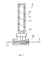
- FIG. 1 shows a schematic illustration of an exemplary structure of an extruder used to form the coating layer. Hatching is omitted in FIG. 1 .
- An extruder 1 includes an extruder body 11 and a crosshead portion 15.
- the extruder body 11 includes a cylinder 12, a screw 13, and other components, including a heater (not shown).
- a material 14 for forming the coating layer is supplied into the cylinder 12 through a hopper (not shown), and, after heat-melted by the heater, sent to the crosshead portion 15 by the rotation of the screw 13.
- the material 14 is extruded onto a surface of a reinforcing fiber bundle 21, which is transported by a transport mechanism (not shown) to move in one direction relative to the crosshead portion 15 of the extruder 1. This forms the coating layer and thus a reinforcing cord 2.
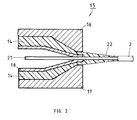
- FIG. 2 shows an enlarged, cross sectional view of an example of the crosshead portion 15.
- the crosshead portion 15 includes dice 16 and 17, and a cored bar 18 having a land portion.
- the material 14, in a molten state, is sent from the extruder body into the space between the dice 16 and 17, and the cored bar 18.
- the material 14 is extruded onto a surface of the reinforcing fiber bundle 21 to form a coating layer 22 and thus the reinforcing cord 2.
- the form of the dice which is split in this example, is not limited.
- the configuration of the extruder is not limited to the example shown in FIG. 1 and FIG. 2 .
- the extruder can have any configuration as long as it includes a mechanism that allows the material to be extruded and adhered to a surface of the reinforcing fiber bundle.
- the reinforcing fiber be provided with a primary coating layer in advance, in order to further improve bending resistance and strength.
- the primary coating layer can be formed by, for example, immersing the reinforcing fiber, such as the glass fiber described above, in a fiber treatment agent containing a rubber latex, followed by drying.
- the primary coating layer for the reinforcing fiber when the reinforced product requires strength or bending resistance in particular.
- the reinforcing fibers will not be in direct contact with one another, making it possible to prevent damage to the reinforcing fibers and improve the strength and bending resistance of the reinforcing cord.
- the primary coating layer can be formed by coating the reinforcing fiber with an aqueous, fiber treatment agent (hereinafter, also referred to as an "aqueous treatment agent") containing a rubber latex, followed by drying and curing. The following more specifically describes the primary coating layer.
- an aqueous, fiber treatment agent hereinafter, also referred to as an "aqueous treatment agent" containing a rubber latex
- the primary coating layer of the present embodiment can be formed with an aqueous treatment agent primarily containing a rubber latex.
- the rubber latex may be at least one selected from, for example, a vinylpyridine-styrene-butadiene terpolymer latex, a butadiene latex, a butadiene-styrene copolymer latex, a dicarboxylated butadiene-styrene copolymer latex, an ethylene propylene latex, a chlorosulfonated polyethylene latex, a fluororubber latex, an acrylic rubber latex, and a hydrogenated nitrile rubber latex.
- the rubber latex contained in the aqueous treatment agent may be either one of, or more than one of these materials.
- "primarily containing a rubber latex” means that the content of the rubber latex in the fiber treatment agent is 20 mass% or greater.
- the aqueous treatment agent may also contain an emulsion or water dispersion of polyurethane resin, epoxy resin, acrylic resin, phenol resin, melamine resin, or low-molecular polyolefin resin.
- the aqueous treatment agent may contain a resorcin-formaldehyde condensate, in order to improve the adhesion between the reinforcing fiber and the latex.
- the aqueous treatment agent is not necessarily required to include a resorcin-formaldehyde condensate. This is because, in the reinforcing cord of the present embodiment, the structure of the reinforcing fibers is maintained by the coating layer formed by extrusion molding. That is, the reinforcing cord of the present embodiment can be formed without using formaldehyde, making the product more environmentally friendly.
- the aqueous treatment agent may contain carbon black. Being an inexpensive inorganic filler, the carbon black can reduce the manufacturing cost of the reinforcing cord.
- the aqueous treatment agent also may appropriately contain other components, such as inorganic fillers other than carbon black, plasticizers, antioxidants, metal oxides, crosslinkers, and crosslinking coagents.
- inorganic filler silica particles may be used.
- the aqueous treatment agent may contain both the resorcin-formaldehyde condensate and carbon black.
- the aqueous treatment agent is in the form of a dispersion of the constituting components of the primary coating layer in an aqueous solvent.
- the aqueous solvent is easy to handle and makes it easier to control the concentration of the constituting components. Further, the aqueous solvent is much more environmentally friendly than organic solvents.
- the content of the resorcin-formaldehyde condensate is preferably 0 to 100 with respect to the mass, 100, of the rubber latex, in terms of a mass ratio of solid contents.
- the content of the resorcin-formaldehyde condensate in the aqueous, fiber treatment agent is too high, the relatively smaller fraction of the rubber latex makes the primary coating layer too hard, with the result that the bending resistance of the product decreases. It is therefore preferable that the content of the resorcin-formaldehyde condensate be in a range of from 5 to 30.
- the method of coating the reinforcing fiber with the aqueous treatment agent to form the primary coating layer is not particularly limited.
- the primary coating layer can be formed by immersing the reinforcing fiber in a water tank containing the aqueous treatment agent, and then removing water in a drying furnace after taking the reinforcing fiber from the tank.
- the drying conditions for water removal are not particularly limited. For example, water can be removed by exposure to an 80°C to 320°C atmosphere for 0.1 to 2 minutes.
- the adhesion rate of the primary coating layer is the mass percentage of the primary coating layer that remains adhered to the reinforcing fiber, such as the glass fiber, in the reinforcing cord after drying.
- the adhesion rate of the primary coating layer is preferably 10 to 30 mass%, and more preferably 12 to 25 mass%. When the adhesion rate is less than 10 mass%, it becomes difficult to cover the entire surface of the reinforcing fiber bundle with the primary coating layer.
- the adhesion rate exceeds 30 mass%, dripping of the aqueous treatment agent becomes likely in forming the primary coating layer. Further, because the primary coating layer becomes too thick in this case, the characteristics of the reinforcing cord may be varied in portions closer to the center of the cord and in portions at the periphery, among others.
- an overcoat layer may be provided on the coating layer, in order to further improve the adhesion with the matrix.
- the treatment agent used to form the overcoat layer may include, for example, rubber, a crosslinker, carbon black, a solvent, and an adhesive.
- rubber included in the treatment agent those containing chlorosulfonated polyethylene as a main component preferably can be used, for example.
- the thickness of the overcoat layer is not particularly limited, and it can be set within a range of from 5 ⁇ m to 100 ⁇ m, for example.
- the overcoat layer of the present embodiment can be formed by common, known methods.
- the overcoat layer can be formed by applying the treatment agent on a surface of the reinforcing cord provided with the coating layer, followed by drying. The cycle of application and drying may be repeated to form an overcoat layer covering the entire surface of the reinforcing cord.
- the overcoat layer effectively improves the adhesion between the reinforcing cord and the matrix.
- the reinforcing cord of the present embodiment obtained in the manner described above can be embedded in the matrix to produce a product reinforced by the reinforcing cord.
- the reinforcing cord can be embedded in a rubber matrix to produce a rubber product reinforced by the reinforcing cord.
- the means to embed and provide the reinforcing cord of the present embodiment in the matrix of the product such as a belt is not particularly limited.
- the reinforcing cord can be embedded in the matrix by a means commonly used in manufacture of toothed belts for automobiles or printers. With the reinforcing cord of the present embodiment embedded in the product, the durability of the product can be improved.
- the matrix of the belt preferably may be a rubber whose main components are hydrogenated nitrile rubber and hydrogenated nitrile rubber containing small amounts of zinc methacrylate dispersed therein, a rubber whose main components are chloroprene rubber or ethylenepropylene rubber, or a polymer material such as polyurethane, for example.
- the matrix of the belt is the polyester thermoplastic elastomer or the fluororesin thermoplastic elastomer used to form the coating layer
- the adhesion between the reinforcing cord and the matrix will be sufficient even when the reinforcing cord is not provided with the overcoat layer.
- Example 1 three glass fibers (each being a bundle of 200 filaments having an average diameter of 9 ⁇ m, E-glass composition) were aligned with one another.
- the glass fibers were immersed in a water tank containing an aqueous treatment agent shown in Table 1. Out of the water tank, the glass fibers were dried for one minute in a drying furnace that had been set to 150°C. As a result, reinforcing fibers with a primary coating layer were obtained.
- Table 1 Composition of aqueous treatment agent Content H-NBR (solid mass percentage 40%) *1 100 parts by mass Resorcin-formaldehyde condensate 10 parts by mass *1 Hydrogenated nitrile rubber latex (Zetpol Latex, Zeon)
- the glass fibers were primarily twisted at a rate of 8 times/10 cm, and eleven such primary helices were aligned and finally twisted at a rate of 8 times/10 cm to obtain a reinforcing fiber bundle.
- the adhesion rate of the primary coating layer with respect to the mass of the reinforcing fiber bundle was 20 mass%.
- a coating layer about 0.1 mm thick, was formed on a surface of the reinforcing fiber bundle with an extruder shown in FIG. 1 , using the polyester thermoplastic elastomer Hytrel ® 7277 (Du Pont-Toray Co., Ltd.). The coating layer was formed at a temperature of 220°C.
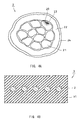
- FIG. 3 shows the surface of the reinforcing cord of this example provided with the coating layer formed by extrusion molding, as observed with a scanning electron microscope (SEM; JSM-T330A; JEOL Ltd.). Observation was made under an applied voltage of 20 kV.
- SEM scanning electron microscope
- JSM-T330A JSM-T330A
- JEOL Ltd. Observation was made under an applied voltage of 20 kV.
- the surface of the coating layer, formed by the characteristic extrusion molding of the present invention was very smooth and did not have any pores that would permit entry of water or oil.
- the thickness of the coating layer was about 0.1 mm, and the outer diameter of the cord was 1.4 mm, as opposed to 1.2 mm before coating.
- the overcoat layer was formed on the reinforcing cord.
- the overcoat layer was formed by applying a mixture of chlorosulfonated polyethylene, isocyanate, carbon black, P-nitrosobenzene, xylene, and toluene, followed by drying. In this example, the cycle of application and drying was repeated twice to form the overcoat layer.
- FIG. 4A shows a schematic cross section of the reinforcing cord of this example formed as above.
- the reinforcing cord 2 of this example has a primary coating layer 23 on the surfaces of the glass fibers 20 each made up of a bundle of filaments.
- the glass fibers 20 are twisted to form a reinforcing fiber bundle 21, and a coating layer 22 is formed on the surface of the reinforcing fiber bundle 21.
- An overcoat layer 24 is formed on the surface of the coating layer 22 to form the reinforcing cord 2 of this example.
- hatching is omitted for clarity of the visible outline.
- the reinforcing cord of this example was used to make a flat belt. According to the procedure of press molding, the reinforcing cords of this example were embedded in the matrix of the composition shown in Table 2 to form a flat belt having a width of 19 mm and a thickness of 5 mm. The length of the belt portion was 300 mm.
- FIG. 4B shows a schematic cross section of a flat belt 3 formed in this example.
- the flat belt 3 includes the reinforcing cords 2 embedded in the matrix, a rubber 31.
- [Table 2] Composition of matrix Content H-NBR *2 70 parts by mass H-NBR/ZDMA *3 30 parts by mass ZnO 10 parts by mass Stearic acid 1 part by mass Carbon black 30 parts by mass Trioctyltrimellitate 5 parts by mass Sulfur 0.1 parts by mass 1,3-bis( t -butylperoxyisopropyl)benzene 6 parts by mass *2 water-soluble hydrogenated nitrile rubber (Zetpol 2020, Zeon) *3 water-soluble hydrogenated nitrile rubber/zinc methacrylate (ZSC 2000L, Zeon)
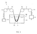
- the product was tested to evaluate durability. Specifically, the flat belt was set in a bending tester 5 shown in FIG. 5 , and an initial and a final tensile strength of the flat belt was measured. These tensile strength values were then used to determine a strength retention, according to the formula below. The strength retention was used as a measure of product durability. To measure the tensile strength, a 250 mm-long sample was chucked and pulled at 50 mm/min in the lengthwise direction, and the maximum stress value at the breaking point of the cord (sample) was recorded.
- the bending tester 5 includes a heating bath 50 providing a test environment.
- One end of the reinforcing cord 2 is attached to a linear motor 51, and the rest is suspended by a series of pulleys 52.
- the flat belt 3 is bent by a roller 53, the periphery of which is kept in the heating bath 50.
- the other end of the reinforcing cord 2 is attached to a weight 54 by being suspended by the pulleys 52.
- the test piece was moved back and forth by the linear motor 51 to repeat a bending test for the flat belt 3 rolled around the roller 53.
- the heating bath 50 can be charged with a liquid 55 (here, water or oil) to perform the bending test.
- the bending test was performed under three environmental conditions: heat, water, and oil. The number of bend was 20,000 in each test.
- Table 3 also shows the result of water absorbance measurement, which was performed by immersing the reinforcing cord of this example in a 96°C hot water for 24 hours.
- Table 3 also shows the result of oil absorbance measurement, which was performed by immersing the reinforcing cord of this example in a 120°C oil for 24 hours.
- the water absorbance and oil absorbance are the percentage obtained by dividing a change in the weight of the reinforcing cord before and after the immersion by the weight of the reinforcing cord before immersion.
- Example 2 As the reinforcing cord of Example 2, the same reinforcing cord used in Example 1 was prepared according to the procedure of Example 1, except that the primary coating layer was omitted (the primary coating layer was not provided). As a product reinforced by the reinforcing cord of Example 2, a flat belt was prepared according to the procedure of Example 1.
- Example 3 The flat belt using the reinforcing cord of Example 2 was subjected to the bending test and immersion test as in Example 1. The results are shown in Table 3.
- Example 1 As the reinforcing cord of Comparative Example 1, the same reinforcing cord used in Example 1 was prepared according to the procedure of Example 1, except that the coating layer was omitted (the coating layer was not provided).
- Example 2 As the reinforcing cord of Comparative Example 2, the same reinforcing cord used in Example 1 was prepared according to the procedure of Example 1, except that the coating layer was prepared from the styrene thermoplastic elastomer TR1086 (JSR).
- JSR styrene thermoplastic elastomer
- Example 3 As the reinforcing cord of Comparative Example 3, the same reinforcing cord used in Example 1 was prepared according to the procedure of Example 1, except that the coating layer was prepared from the polyurethane elastomer Resamine P-2060 (Dainichiseika Color & Chemicals Mfg. Co., Ltd.).
- Example 1 Example 2 Comparative Example 1 Comparative Example 2 Comparative Example 3 Preparation conditions of reinforcing cord Primary coating layer H-NBR+RF *4 Not provided H-NBR+RF *4 H-NBR+RF *4 H-NBR+RF *4 Coating layer Hytrel 7277 Hytrel 7277 Not provided TR 1086 P-2060 Overcoat layer Provided Provided Provided Provided Provided Provided Provided Strength retention of flat belt (%) Heat test 98 85 83 84 82 Water test 96 65 60 85 70 Oil test 90 60 46 52 46 Water absorbance and oil absorbance of reinforcing cord (%) Water immersion test 3.9 3.9 12.7 3.9 4.1 Oil immersion test 3.5 3.5 14.5 3.5 3.5 *4 Mixture of water-soluble hydrogenated nitrile rubber (H-NBR) and resorcin-formaldehyde (RF) condensate
- H-NBR water-soluble hydrogenated nitrile rubber
- RF resorcin-formaldehyde
- Example 3 It was found from the results shown in Table 3 that the coating layer formed by extrusion molding is highly effective in preventing entry of water or oil into the reinforcing cord. It was also found from the bending test for the flat belts that the strength retention can be greatly improved by the formation of the coating layer.
- the strength retention in the bending test was higher in Example 1 using the polyester thermoplastic elastomer for the coating layer, compared with Comparative Example 2 using the styrene thermoplastic elastomer for the coating layer, and Comparative Example 3 using the polyurethane elastomer for the coating layer. It was therefore confirmed that the bending resistance can be improved by forming the coating layer with the polyester thermoplastic elastomer.
- Example 2 It was found from the result of Example 2 that the coating layer formed with the polyester thermoplastic elastomer can provide sufficient water resistance and oil resistance even when the primary coating layer is not provided. The strength was sufficient as well.
- Example 4 As the reinforcing cords of Examples 3 and 4 and Comparative Example 4, the same reinforcing cords used in Examples 1 and 2 and Comparative Example 1 were used, respectively, except that the overcoat layer was omitted.
- the fluororesin thermoplastic elastomer THVX815G (Sumitomo 3M Limited) was used for the coating layer.
- the water absorbance and oil absorbance of these reinforcing cords were measured as in Example 1. The results are shown in Table 4.
- Example 3 Example 4 Example 5 Comparative Example 4 Preparation conditions of reinforcing cord Primary layer coating H-NBR+RF *5 Not provided H-NBR+RF *5 H-NBR+RF *5 Coating layer Hytrel 7277 Hytrel 7277 THVX 815G Not provided Overcoat layer Not provided Not provided Provided Not provided Water absorbance and oil absorbance of reinforcing cord (%) Water immersion test 5.0 4.8 4.7 32.3 Oil immersion test 3.1 3.2 3.0 29.3 *5 Mixture of water-soluble hydrogenated nitrile rubber (H-NBR) and resorcin-formaldehyde (RF) condensate
- H-NBR water-soluble hydrogenated nitrile rubber
- RF resorcin-formaldehyde
- the polyester elastomer and the fluororesin elastomer are suitable for rubber reinforcing cords.
- a reinforcing cord was prepared that had the coating layer formed by extrusion molding of NBR (nitrile rubber).
- NBR nitrile rubber
- the thickness of the coating layer could not be reduced to more than 0.3 mm, and a coating layer with a thickness of 0.1 mm was unattainable.
- the outer diameter of the cord was 1.8 mm.
- a reinforcing cord of the present invention With a reinforcing cord of the present invention and a method of production thereof, a reinforcing cord can be provided that has desirable water resistance, oil resistance, and bending resistance.
- the invention therefore suitably can be used to reinforce products using rubber and polymer materials such as polyurethane as a matrix.
- the products reinforced by a reinforcing cord of the present invention can withstand a heavy load, and are therefore usable in applications, for example, such as toothed belts, requiring durability.
- a reinforcing cord of the present invention can be used in place of an organic fiber rope or a steel wire to provide improved bending resistance and increase life.
Landscapes
- Engineering & Computer Science (AREA)
- Mechanical Engineering (AREA)
- Chemical & Material Sciences (AREA)
- Life Sciences & Earth Sciences (AREA)
- Chemical Kinetics & Catalysis (AREA)
- General Life Sciences & Earth Sciences (AREA)
- Textile Engineering (AREA)
- General Chemical & Material Sciences (AREA)
- Geochemistry & Mineralogy (AREA)
- Materials Engineering (AREA)
- Organic Chemistry (AREA)
- Treatments For Attaching Organic Compounds To Fibrous Goods (AREA)
- Ropes Or Cables (AREA)
- Extrusion Moulding Of Plastics Or The Like (AREA)
- Yarns And Mechanical Finishing Of Yarns Or Ropes (AREA)
Abstract
Description
- The present invention relates to a reinforcing cord, a method for producing it, and products reinforced by the reinforcing cord, and particularly to a reinforcing cord for rubbers, a method for producing such reinforcing cords, and rubber products reinforced by the reinforcing cords.
- To improve the strength or durability of products such as toothed rubber belts, reinforcing fibers such as glass fiber or chemical fiber are commonly embedded in the matrix. However, after long use, the strength of the products often drops as a result of the fatigue that accumulates in the reinforcing fibers by bending. It is also known that the deterioration in the strength of the products accelerates when there is entry of water or oil in the products, causing the coating layer of the reinforcing fibers to swell and unwinding the twist in the fiber bundle.
- Under these circumstances, various designs have been made for the reinforcing fibers, in order to improve bending resistance of the products, and reduce the change in property of the products in response to entry of water or oil. For example,
JP2003-253568A JP2003-268678A -
JP11(1999)-217739A - However, the coating layer formed by immersing the fibers in a treatment agent or coating the fibers with a treatment agent is susceptible to pore formation attributed to the producing method. This makes it difficult to completely prevent entry of water or oil. Accordingly, there is difficulty improving the durability of the products, such as toothed belts, with the use of the reinforcing cords formed by the foregoing methods.
- Further, when a rubber belt reinforced by the reinforcing cords produced by the foregoing methods is bent hard, there are cases where the bending stress acting on the reinforcing cords unwinds the twist in the reinforcing fibers, lowering the breaking strength of the belt.
- Further, when the rubber belt reinforced by the reinforcing cords is used for extended time periods under high temperature conditions, there are cases where the coating layer, formed by drying and curing the latex, gradually hardens and becomes less resistant to bending.
- In view of these problems,
JP11(1999)-13836A JP2004-17378A JP2004-316049A - However, forming a rubber layer (coating layer) on the surface of the reinforcing fiber by the extrusion of a material is problematic in that the coating layer does not have sufficient heat resistance or creep resistance (shape stability), damaging the coating layer and causing entry of water or oil into the cord after long use. Another problem of forming a coating layer (rubber layer) by the foregoing method is the difficulty forming a uniform, thin layer, increasing the external size of the reinforcing cord.
- The present invention was made in view of the foregoing problems, and it is an object of the invention to provide a reinforcing cord having desirable water and oil resistance realized by suppressing entry of water or oil into the reinforcing cord, and desirable bending resistance realized by preventing the bend-incurred unwinding of the twist in the fibers. The invention also provides a method for producing such reinforcing cords, and products using such reinforcing cords as a reinforcing member.
- A producing method of a reinforcing cord of the present invention is a method for producing a reinforcing cord including a bundle of reinforcing fibers and a coating layer formed on a surface of the reinforcing fiber bundle, the method including extruding a material containing at least one selected from a polyester thermoplastic elastomer and a fluororesin thermoplastic elastomer to cause the extruded material to adhere to the surface of the reinforcing fiber bundle and form the coating layer. In the descriptions below, the process of forming the coating layer, in which the material is extruded to adhere to a surface of the reinforcing fiber bundle may be referred to as extrusion molding.
- A reinforcing cord of the present invention is produced by a producing method of the present invention.
- A product of the present invention includes a reinforcing cord of the present invention as a reinforcing member.
- A reinforcing cord of the present invention, and a reinforcing cord obtained by a producing method of the present invention (hereinafter, also referred to as a reinforcing cord obtained by the present invention) include a coating layer, formed by extrusion molding, containing at least one selected from a polyester thermoplastic elastomer and a fluororesin thermoplastic elastomer. With such a coating layer, deformation or damage is unlikely to occur in the coating layer even after long use, and entry of water or oil through pores or cracks can be prevented to realize desirable water resistance and oil resistance. Accordingly, a product of the present invention, using the reinforcing cord, can have significantly improved water resistance and oil resistance.
- In a reinforcing cord obtained by the present invention, a thermoplastic elastomer is used for the extrusion molding of the coating layer. This forms a film having a thinner, and more uniform thickness than films using rubber. Another advantage of the invention, then, is that it can provide a thin reinforcing cord. With current techniques, it is difficult to form a film having a thin and uniform thickness by the extrusion molding of a rubber material. Generally, the practical thickness of a film using a rubber material is about 0.3 mm at best. By contrast, the thickness can be reduced to about 0.1 mm when the thermoplastic elastomer is used.
- Further, in a reinforcing cord obtained by the present invention, the reinforcing fiber bundle in the cord remains strongly bonded together by the coating layer formed by extrusion molding, even after long use. Thus, the reinforcing fiber bundle does not easily unwind even under severe bending conditions, and exhibits desirable bending resistance. Accordingly, a product of the present invention, using the reinforcing cord, can have significantly improved bending resistance.
- Further, a reinforcing cord obtained by the present invention, with the sufficient oil resistance and water resistance, does not require forming a primary coating layer using a material that excels in oil resistance and water resistance. This allows for use of an inexpensive material (for example, a latex or water-soluble resin) for the primary coating layer when it is formed under the coating layer, making it possible to reduce the manufacturing cost of the reinforcing cord.
- As described, a reinforcing cord obtained by the present invention excels in bending resistance, water resistance, and oil resistance. Accordingly, a product of the present invention, using the reinforcing cord as a reinforcing member, can have improved durability.
-
-
FIG. 1 is a schematic diagram showing a structure of an example of an extruder used to form a coating layer of a reinforcing cord of the present invention. -
FIG. 2 is a schematic cross sectional view depicting an example of a crosshead portion of the extruder shown inFIG. 1 . -
FIG. 3 is a scanning electron micrograph, substituted for drawing, showing a surface of a coating layer of a reinforcing cord according to an example of the present invention. -
FIG. 4A is a schematic cross sectional view showing an example of a structure of a reinforcing cord of the present invention. -
FIG. 4B is a schematic cross sectional view showing a structure of a flat belt as an example of a product reinforced by a reinforcing cord of the present invention. -
FIG. 5 is a schematic view depicting a bending tester. - The following will describe an embodiment of the present invention.
- A method for producing a reinforcing cord of an embodiment of the present invention includes forming a coating layer, containing at least one selected from a polyester thermoplastic elastomer and a fluororesin thermoplastic elastomer, on a surface of a reinforcing fiber bundle by extrusion molding.
- The method for producing a reinforcing cord of the present embodiment may further include twisting reinforcing fibers to form the reinforcing fiber bundle, before forming the coating layer.
- The method for producing a reinforcing cord of the present embodiment may further include forming a primary coating layer on a surface of the reinforcing fiber, before forming the coating layer. In this case, the method may further include twisting the reinforcing fibers with the primary coating layer to form the reinforcing fiber bundle, after forming the primary coating layer on the reinforcing fibers and before forming the coating layer. When forming the primary coating layer, the primary coating layer can be formed by using a fiber treatment agent containing a rubber latex. The rubber latex may be at least one selected from, for example, a vinylpyridine-styrene-butadiene terpolymer latex, a butadiene latex, a butadiene-styrene copolymer latex, a dicarboxylated butadiene-styrene copolymer latex, an ethylene propylene latex, a chlorosulfonated polyethylene latex, a fluororubber latex, an acrylic rubber latex, and a hydrogenated nitrile rubber latex.
- The method for producing a reinforcing cord of the present embodiment may further include forming an overcoat layer using a material containing rubber, the overcoat layer being formed on the coating layer after forming the coating layer. In this case, the rubber may be, for example, a rubber containing chlorosulfonated polyethylene as a main component. As used herein, the "rubber containing chlorosulfonated polyethylene as a main component" means that the content of chlorosulfonated polyethylene is 50 mass% or greater with respect to the entire rubber component.
- The following more specifically describes a method for producing a reinforcing cord of the present embodiment.
- The reinforcing fiber used in a method for producing a reinforcing cord of the present embodiment is not limited to particular shapes or materials as long as it can reinforce the product.
- Examples of the reinforcing fiber include: glass fibers; polyvinyl alcohol fibers represented by vinylon fibers; polyester fibers; polyamide fibers such as nylon and aramids (aromatic polyamides); polyarylate fibers; polyketone fibers; carbon fibers; and poly(p-phenylene benzooxazole) (PBO). Among these examples, glass fibers, that excel in properties such as dimension stability, heat resistance, and tensile strength, are suitably used. For example, when forming a reinforcing cord used to reinforce a toothed belt requiring high durability, it is preferable to use a glass fiber having sufficient strength.
- The type of glass in the glass fibers is not particularly limited. However, high-strength glass, that excels in tensile strength, is more preferable to common alkali-free glass.
- The fiber configuration is not particularly limited. In the case of glass fibers for example, it is preferable that the filament, the smallest constituting unit of the fiber, have an average diameter of from 5 µm to 13 µm. For example, a number of such filaments, 50 to 2,000, are bound together with a binder, and one or more of the filament constructs are aligned to form the reinforcing fiber. A number of these reinforcing fibers are then aligned to form a bundle of reinforcing fibers. Thereafter, a coating layer is formed on a surface of the reinforcing fiber bundle by extrusion molding. A method of forming a coating layer will be described later.
- For example, the bundle of reinforcing fibers may be formed by primarily twisting the reinforcing fibers, aligning these fibers, and final twisting the aligning fibers in the opposite twist direction with respect to the twist direction of the primary twist.
- The method of forming the bundle of reinforcing fibers is not limited to the one described above, and it can be formed in various ways, for example, by not giving the final twist, giving the primary twist and the final twist in the same direction, using different fiber materials for the central portion and the outer portion of the reinforcing fiber bundle, or giving the primary twist and the final twist in opposite directions. The bundle of reinforcing fibers so twisted is suitable for products requiring bending resistance, such as the reinforcing cord for toothed belts.
- As described, the reinforcing fiber bundle of the present embodiment is formed by binding a plurality of reinforcing fibers. The reinforcing fibers may be surface-coated with a primary coating layer before they are used to form the bundle of reinforcing fibers. Details of the primary coating layer will be described later.
- The reinforcing cord of the present embodiment includes a coating layer formed by extrusion molding. Preferably, the coating layer should be flexible (elastic) to improve bending resistance. As such, materials that exhibit flexible, elastomeric properties at ordinary temperature are preferably used. As used herein, the "flexible, elastomeric properties" means having a Shore A hardness (JIS K6253) of 100 or less, or a Shore D hardness (JIS K6253) of 80 or less, for example.
- The coating layer of the present embodiment is formed of a material containing at least one selected from a polyester thermoplastic elastomer and a fluororesin thermoplastic elastomer, because these materials are resistant to deformation or damage that might occur during long use, and excel in moldability and ease of thickness control, among others reasons. The material used to form the coating layer contains at least one selected from a polyester thermoplastic elastomer and a fluororesin thermoplastic elastomer in the amount of preferably 20 mass% or greater, and more preferably 50 mass% or greater, or the content may be even 100 mass%, by solely containing at least one of a polyester thermoplastic elastomer and a fluororesin thermoplastic elastomer. The polyester thermoplastic elastomer and the fluororesin thermoplastic elastomer preferably should be selected such that the material does not dissolve or foam in the temperature range of the step in which the overcoat layer is formed after forming the coating layer, or the step in which the reinforcing cord is embedded in the matrix. Further, since the coating layer needs to have adhesion to the matrix and the overcoat layer, it is preferable that the material used for the coating layer be compatible with properties to the matrix and the overcoat layer. Preferably, the coating layer is made of a material containing a polyester thermoplastic elastomer, because such material has superior properties, including bondability to the materials commonly used for the matrix and the overcoat layer. Preferably, the material contains a polyester thermoplastic elastomer in the amount of, for example, 50 mass% or greater.
- Examples of the polyester thermoplastic elastomer include Hytrel (Du Pont-Toray Co., Ltd.), Pelprene (Toyobo), Glylux (Dainihon Ink Co., Ltd.), and Nouvelan (Teijin Limited). Examples of the fluororesin thermoplastic elastomer include DAI-EL Thermoplastic (Daikin Industries, Ltd.) and THV (Sumitomo 3M Limited).
- The material used to form the coating layer may additionally contain a short glass fiber, carbon black, silica, or various kinds of organic fibers, in order to alter moldability, molding conditions, or properties after molding.
- The coating layer, formed by extrusion molding using a material containing at least one selected from a polyester thermoplastic elastomer and a fluororesin thermoplastic elastomer is materially denser (less susceptible to pore formation) than traditional coating layers formed by impregnating a latex. Thus, the reinforcing cord of the present embodiment can prevent entry of foreign substances, such as water or oil, into the material. Further, since the coating layer of the present embodiment is materially strong and integrally formed by extrusion molding, it has strong cohesion to the material confined therein. The coating layer therefore excels in the ability to retain the structure of the reinforcing fiber bundle it confines, particularly in a reinforcing cord in which the reinforcing fibers are twisted.
- Further, by selecting a material containing at least one selected from a polyester thermoplastic elastomer and a fluororesin thermoplastic elastomer, the coating layer can have excellent heat resistance and creep resistance (shape stability), making it possible to fabricate a reinforcing cord that can withstand long use.
- The thickness of the coating layer is not particularly limited, and it can be set within a range of, for example, from 0.05 mm to 5.0 mm. When a thin cord is needed, a 0.05 to 1.0 mm range is preferable to reduce the overall diameter of the cord.
- In the following, description is made as to extrusion molding.
- In the present embodiment, the coating layer is formed by extruding the material of the coating layer with an extruder to continuously adhere the coating layer material to a surface of the reinforcing fiber bundle moved relative to the extruder. Specifically, the coating layer is formed with an extruder shown in
FIG. 1 andFIG. 2 , for example. -
FIG. 1 shows a schematic illustration of an exemplary structure of an extruder used to form the coating layer. Hatching is omitted inFIG. 1 . Anextruder 1 includes anextruder body 11 and acrosshead portion 15. Theextruder body 11 includes acylinder 12, ascrew 13, and other components, including a heater (not shown). Amaterial 14 for forming the coating layer is supplied into thecylinder 12 through a hopper (not shown), and, after heat-melted by the heater, sent to thecrosshead portion 15 by the rotation of thescrew 13. At thecrosshead portion 15, thematerial 14 is extruded onto a surface of a reinforcingfiber bundle 21, which is transported by a transport mechanism (not shown) to move in one direction relative to thecrosshead portion 15 of theextruder 1. This forms the coating layer and thus a reinforcingcord 2. -
FIG. 2 shows an enlarged, cross sectional view of an example of thecrosshead portion 15. InFIG. 2 , thecrosshead portion 15 includesdice 16 and 17, and a coredbar 18 having a land portion. Thematerial 14, in a molten state, is sent from the extruder body into the space between thedice 16 and 17, and the coredbar 18. Here, thematerial 14 is extruded onto a surface of the reinforcingfiber bundle 21 to form acoating layer 22 and thus the reinforcingcord 2. The form of the dice, which is split in this example, is not limited. Further, the configuration of the extruder is not limited to the example shown inFIG. 1 andFIG. 2 . The extruder can have any configuration as long as it includes a mechanism that allows the material to be extruded and adhered to a surface of the reinforcing fiber bundle. - In the reinforcing cord of the present embodiment, it is preferable that the reinforcing fiber be provided with a primary coating layer in advance, in order to further improve bending resistance and strength.
- The primary coating layer can be formed by, for example, immersing the reinforcing fiber, such as the glass fiber described above, in a fiber treatment agent containing a rubber latex, followed by drying.
- It is preferable to provide the primary coating layer for the reinforcing fiber when the reinforced product requires strength or bending resistance in particular. By providing the primary coating layer, the reinforcing fibers will not be in direct contact with one another, making it possible to prevent damage to the reinforcing fibers and improve the strength and bending resistance of the reinforcing cord.
- The primary coating layer can be formed by coating the reinforcing fiber with an aqueous, fiber treatment agent (hereinafter, also referred to as an "aqueous treatment agent") containing a rubber latex, followed by drying and curing. The following more specifically describes the primary coating layer.
- The primary coating layer of the present embodiment can be formed with an aqueous treatment agent primarily containing a rubber latex. The rubber latex may be at least one selected from, for example, a vinylpyridine-styrene-butadiene terpolymer latex, a butadiene latex, a butadiene-styrene copolymer latex, a dicarboxylated butadiene-styrene copolymer latex, an ethylene propylene latex, a chlorosulfonated polyethylene latex, a fluororubber latex, an acrylic rubber latex, and a hydrogenated nitrile rubber latex. That is, the rubber latex contained in the aqueous treatment agent may be either one of, or more than one of these materials. As used herein, "primarily containing a rubber latex" means that the content of the rubber latex in the fiber treatment agent is 20 mass% or greater.
- The aqueous treatment agent may also contain an emulsion or water dispersion of polyurethane resin, epoxy resin, acrylic resin, phenol resin, melamine resin, or low-molecular polyolefin resin.
- Further, the aqueous treatment agent may contain a resorcin-formaldehyde condensate, in order to improve the adhesion between the reinforcing fiber and the latex. In the present embodiment, the aqueous treatment agent is not necessarily required to include a resorcin-formaldehyde condensate. This is because, in the reinforcing cord of the present embodiment, the structure of the reinforcing fibers is maintained by the coating layer formed by extrusion molding. That is, the reinforcing cord of the present embodiment can be formed without using formaldehyde, making the product more environmentally friendly.
- Further, the aqueous treatment agent may contain carbon black. Being an inexpensive inorganic filler, the carbon black can reduce the manufacturing cost of the reinforcing cord.
- The aqueous treatment agent also may appropriately contain other components, such as inorganic fillers other than carbon black, plasticizers, antioxidants, metal oxides, crosslinkers, and crosslinking coagents. As the inorganic filler, silica particles may be used.
- The aqueous treatment agent may contain both the resorcin-formaldehyde condensate and carbon black.
- Preferably, the aqueous treatment agent is in the form of a dispersion of the constituting components of the primary coating layer in an aqueous solvent. The aqueous solvent is easy to handle and makes it easier to control the concentration of the constituting components. Further, the aqueous solvent is much more environmentally friendly than organic solvents.
- As to the contents of the constituting components of the primary coating layer in the aqueous treatment agent, the content of the resorcin-formaldehyde condensate is preferably 0 to 100 with respect to the mass, 100, of the rubber latex, in terms of a mass ratio of solid contents. When the content of the resorcin-formaldehyde condensate in the aqueous, fiber treatment agent is too high, the relatively smaller fraction of the rubber latex makes the primary coating layer too hard, with the result that the bending resistance of the product decreases. It is therefore preferable that the content of the resorcin-formaldehyde condensate be in a range of from 5 to 30.
- The method of coating the reinforcing fiber with the aqueous treatment agent to form the primary coating layer is not particularly limited. Generally, the primary coating layer can be formed by immersing the reinforcing fiber in a water tank containing the aqueous treatment agent, and then removing water in a drying furnace after taking the reinforcing fiber from the tank. The drying conditions for water removal are not particularly limited. For example, water can be removed by exposure to an 80°C to 320°C atmosphere for 0.1 to 2 minutes.
- The following describes the adhesion rate of the primary coating layer. The adhesion rate R of the primary coating layer is the mass percentage of the primary coating layer that remains adhered to the reinforcing fiber, such as the glass fiber, in the reinforcing cord after drying. The adhesion rate R is given by the following equation.

where C0 is the dry mass of the reinforcing fiber before coating, and C1 is the dry mass of the reinforcing fiber after coating. - The adhesion rate of the primary coating layer is preferably 10 to 30 mass%, and more preferably 12 to 25 mass%. When the adhesion rate is less than 10 mass%, it becomes difficult to cover the entire surface of the reinforcing fiber bundle with the primary coating layer.
- When the adhesion rate exceeds 30 mass%, dripping of the aqueous treatment agent becomes likely in forming the primary coating layer. Further, because the primary coating layer becomes too thick in this case, the characteristics of the reinforcing cord may be varied in portions closer to the center of the cord and in portions at the periphery, among others.
- In the reinforcing cord of the present embodiment, an overcoat layer may be provided on the coating layer, in order to further improve the adhesion with the matrix. The treatment agent used to form the overcoat layer may include, for example, rubber, a crosslinker, carbon black, a solvent, and an adhesive. As the rubber included in the treatment agent, those containing chlorosulfonated polyethylene as a main component preferably can be used, for example. The thickness of the overcoat layer is not particularly limited, and it can be set within a range of from 5 µm to 100 µm, for example.
- The overcoat layer of the present embodiment can be formed by common, known methods. For example, the overcoat layer can be formed by applying the treatment agent on a surface of the reinforcing cord provided with the coating layer, followed by drying. The cycle of application and drying may be repeated to form an overcoat layer covering the entire surface of the reinforcing cord. As noted above, the overcoat layer effectively improves the adhesion between the reinforcing cord and the matrix.
- The reinforcing cord of the present embodiment obtained in the manner described above can be embedded in the matrix to produce a product reinforced by the reinforcing cord. For example, the reinforcing cord can be embedded in a rubber matrix to produce a rubber product reinforced by the reinforcing cord. The means to embed and provide the reinforcing cord of the present embodiment in the matrix of the product such as a belt is not particularly limited. When used as a reinforcing member for toothed belts, the reinforcing cord can be embedded in the matrix by a means commonly used in manufacture of toothed belts for automobiles or printers. With the reinforcing cord of the present embodiment embedded in the product, the durability of the product can be improved.
- When the reinforced product is a belt for example, the matrix of the belt preferably may be a rubber whose main components are hydrogenated nitrile rubber and hydrogenated nitrile rubber containing small amounts of zinc methacrylate dispersed therein, a rubber whose main components are chloroprene rubber or ethylenepropylene rubber, or a polymer material such as polyurethane, for example.
- When the matrix of the belt is the polyester thermoplastic elastomer or the fluororesin thermoplastic elastomer used to form the coating layer, the adhesion between the reinforcing cord and the matrix will be sufficient even when the reinforcing cord is not provided with the overcoat layer.
- The following will describe the present invention in more detail based on examples and comparative examples.
- In Example 1, three glass fibers (each being a bundle of 200 filaments having an average diameter of 9 µm, E-glass composition) were aligned with one another. The glass fibers were immersed in a water tank containing an aqueous treatment agent shown in Table 1. Out of the water tank, the glass fibers were dried for one minute in a drying furnace that had been set to 150°C. As a result, reinforcing fibers with a primary coating layer were obtained.
[Table 1] Composition of aqueous treatment agent Content H-NBR (solid mass percentage 40%)*1 100 parts by mass Resorcin-formaldehyde condensate 10 parts by mass *1 Hydrogenated nitrile rubber latex (Zetpol Latex, Zeon) - The glass fibers were primarily twisted at a rate of 8 times/10 cm, and eleven such primary helices were aligned and finally twisted at a rate of 8 times/10 cm to obtain a reinforcing fiber bundle. The adhesion rate of the primary coating layer with respect to the mass of the reinforcing fiber bundle was 20 mass%.
- Then, a coating layer, about 0.1 mm thick, was formed on a surface of the reinforcing fiber bundle with an extruder shown in
FIG. 1 , using the polyester thermoplastic elastomer Hytrel® 7277 (Du Pont-Toray Co., Ltd.). The coating layer was formed at a temperature of 220°C. -
FIG. 3 shows the surface of the reinforcing cord of this example provided with the coating layer formed by extrusion molding, as observed with a scanning electron microscope (SEM; JSM-T330A; JEOL Ltd.). Observation was made under an applied voltage of 20 kV. As clearly shown inFIG. 3 , the surface of the coating layer, formed by the characteristic extrusion molding of the present invention, was very smooth and did not have any pores that would permit entry of water or oil. As noted above, the thickness of the coating layer was about 0.1 mm, and the outer diameter of the cord was 1.4 mm, as opposed to 1.2 mm before coating. - An overcoat layer was formed on the reinforcing cord. The overcoat layer was formed by applying a mixture of chlorosulfonated polyethylene, isocyanate, carbon black, P-nitrosobenzene, xylene, and toluene, followed by drying. In this example, the cycle of application and drying was repeated twice to form the overcoat layer.
-
FIG. 4A shows a schematic cross section of the reinforcing cord of this example formed as above. The reinforcingcord 2 of this example has aprimary coating layer 23 on the surfaces of theglass fibers 20 each made up of a bundle of filaments. Theglass fibers 20 are twisted to form a reinforcingfiber bundle 21, and acoating layer 22 is formed on the surface of the reinforcingfiber bundle 21. Anovercoat layer 24 is formed on the surface of thecoating layer 22 to form the reinforcingcord 2 of this example. InFIG. 4A , hatching is omitted for clarity of the visible outline. - The reinforcing cord of this example was used to make a flat belt. According to the procedure of press molding, the reinforcing cords of this example were embedded in the matrix of the composition shown in Table 2 to form a flat belt having a width of 19 mm and a thickness of 5 mm. The length of the belt portion was 300 mm.
-
FIG. 4B shows a schematic cross section of aflat belt 3 formed in this example. Theflat belt 3 includes the reinforcingcords 2 embedded in the matrix, arubber 31.[Table 2] Composition of matrix Content H-NBR*2 70 parts by mass H-NBR/ZDMA*3 30 parts by mass ZnO 10 parts by mass Stearic acid 1 part by mass Carbon black 30 parts by mass Trioctyltrimellitate 5 parts by mass Sulfur 0.1 parts by mass 1,3-bis(t-butylperoxyisopropyl)benzene 6 parts by mass *2 water-soluble hydrogenated nitrile rubber (Zetpol 2020, Zeon)
*3 water-soluble hydrogenated nitrile rubber/zinc methacrylate (ZSC 2000L, Zeon) - The product (flat belt) was tested to evaluate durability. Specifically, the flat belt was set in a bending
tester 5 shown inFIG. 5 , and an initial and a final tensile strength of the flat belt was measured. These tensile strength values were then used to determine a strength retention, according to the formula below. The strength retention was used as a measure of product durability. To measure the tensile strength, a 250 mm-long sample was chucked and pulled at 50 mm/min in the lengthwise direction, and the maximum stress value at the breaking point of the cord (sample) was recorded. - Strength retention (%) = (final tensile strength/initial tensile strength) × 100
- Referring to
FIG. 5 , the bendingtester 5 includes aheating bath 50 providing a test environment. One end of the reinforcingcord 2 is attached to alinear motor 51, and the rest is suspended by a series ofpulleys 52. Theflat belt 3 is bent by aroller 53, the periphery of which is kept in theheating bath 50. The other end of the reinforcingcord 2 is attached to aweight 54 by being suspended by thepulleys 52. - In this manner, the test piece was moved back and forth by the
linear motor 51 to repeat a bending test for theflat belt 3 rolled around theroller 53. Note that theheating bath 50 can be charged with a liquid 55 (here, water or oil) to perform the bending test. - The bending test was performed under three environmental conditions: heat, water, and oil. The number of bend was 20,000 in each test.
- Heat test:
The content of the heating bath 50: air; ambient temperature: 80°C - Water test:
The content of the heating bath 50: water; ordinary temperature - Oil test
- The test results are shown in Table 3 below.
- Table 3 also shows the result of water absorbance measurement, which was performed by immersing the reinforcing cord of this example in a 96°C hot water for 24 hours. Table 3 also shows the result of oil absorbance measurement, which was performed by immersing the reinforcing cord of this example in a 120°C oil for 24 hours. Here, the water absorbance and oil absorbance are the percentage obtained by dividing a change in the weight of the reinforcing cord before and after the immersion by the weight of the reinforcing cord before immersion.
- As the reinforcing cord of Example 2, the same reinforcing cord used in Example 1 was prepared according to the procedure of Example 1, except that the primary coating layer was omitted (the primary coating layer was not provided). As a product reinforced by the reinforcing cord of Example 2, a flat belt was prepared according to the procedure of Example 1.
- The flat belt using the reinforcing cord of Example 2 was subjected to the bending test and immersion test as in Example 1. The results are shown in Table 3.
- As the reinforcing cord of Comparative Example 1, the same reinforcing cord used in Example 1 was prepared according to the procedure of Example 1, except that the coating layer was omitted (the coating layer was not provided).
- As the reinforcing cord of Comparative Example 2, the same reinforcing cord used in Example 1 was prepared according to the procedure of Example 1, except that the coating layer was prepared from the styrene thermoplastic elastomer TR1086 (JSR).
- As the reinforcing cord of Comparative Example 3, the same reinforcing cord used in Example 1 was prepared according to the procedure of Example 1, except that the coating layer was prepared from the polyurethane elastomer Resamine P-2060 (Dainichiseika Color & Chemicals Mfg. Co., Ltd.).
- According to the procedure of Example 1, flat belts were prepared as the products reinforced by the reinforcing cords of Comparative Examples 1 to 3. The flat belts using the reinforcing cords of Comparative Examples 1 and 2 were subjected to the bending test and immersion test as in Example 1. The results are shown in Table 3.
[Table 3] Example 1 Example 2 Comparative Example 1 Comparative Example 2 Comparative Example 3 Preparation conditions of reinforcing cord Primary coating layer H-NBR+RF*4 Not provided H-NBR+RF*4 H-NBR+RF*4 H-NBR+RF*4 Coating layer Hytrel 7277 Hytrel 7277 Not provided TR 1086 P-2060 Overcoat layer Provided Provided Provided Provided Provided Strength retention of flat belt (%) Heat test 98 85 83 84 82 Water test 96 65 60 85 70 Oil test 90 60 46 52 46 Water absorbance and oil absorbance of reinforcing cord (%) Water immersion test 3.9 3.9 12.7 3.9 4.1 Oil immersion test 3.5 3.5 14.5 3.5 3.5 *4 Mixture of water-soluble hydrogenated nitrile rubber (H-NBR) and resorcin-formaldehyde (RF) condensate - It was found from the results shown in Table 3 that the coating layer formed by extrusion molding is highly effective in preventing entry of water or oil into the reinforcing cord. It was also found from the bending test for the flat belts that the strength retention can be greatly improved by the formation of the coating layer. By comparing the reinforcing cords of Example 1 and Comparative Examples 2 and 3, which differ only in the material of the coating layer, it was found that the strength retention in the bending test was higher in Example 1 using the polyester thermoplastic elastomer for the coating layer, compared with Comparative Example 2 using the styrene thermoplastic elastomer for the coating layer, and Comparative Example 3 using the polyurethane elastomer for the coating layer. It was therefore confirmed that the bending resistance can be improved by forming the coating layer with the polyester thermoplastic elastomer.
- In Comparative Example 2, due to the poor creep resistance, the coating layer underwent severe deformation and pores were formed during the bending test of the flat belt. As a result, the cord lost cohesion and the tensile strength dropped. Entry of water or oil through the pores also occurred, impairing the characteristics of the reinforcing cord.
- It was found from the result of Example 2 that the coating layer formed with the polyester thermoplastic elastomer can provide sufficient water resistance and oil resistance even when the primary coating layer is not provided. The strength was sufficient as well.
- As the reinforcing cords of Examples 3 and 4 and Comparative Example 4, the same reinforcing cords used in Examples 1 and 2 and Comparative Example 1 were used, respectively, except that the overcoat layer was omitted. In the reinforcing cord of Example 5, the fluororesin thermoplastic elastomer THVX815G (Sumitomo 3M Limited) was used for the coating layer. The water absorbance and oil absorbance of these reinforcing cords were measured as in Example 1. The results are shown in Table 4.
[Table 4] Example 3 Example 4 Example 5 Comparative Example 4 Preparation conditions of reinforcing cord Primary layer coating H-NBR+RF*5 Not provided H-NBR+RF*5 H-NBR+RF*5 Coating layer Hytrel 7277 Hytrel 7277 THVX 815G Not provided Overcoat layer Not provided Not provided Provided Not provided Water absorbance and oil absorbance of reinforcing cord (%) Water immersion test 5.0 4.8 4.7 32.3 Oil immersion test 3.1 3.2 3.0 29.3 *5 Mixture of water-soluble hydrogenated nitrile rubber (H-NBR) and resorcin-formaldehyde (RF) condensate - It was found from the results shown in Table 4 that the water absorbance and oil absorbance of the samples using the fluororesin thermoplastic elastomer were comparable to those in the samples using the polyester thermoplastic elastomer.
- From the results shown in Tables 3 and 4, it was found that the coating layer formed by extrusion molding using the polyester thermoplastic elastomer or the fluororesin thermoplastic elastomer is highly effective in preventing entry of water or oil into the reinforcing cord, irrespective of whether the overcoat layer is formed.
- One of the characteristics of the polyester elastomer and the fluororesin elastomer is that they have a good balance of desirable properties such as heat resistance, cold resistance, and oil resistance. In particular, the polyester elastomer, with its excellent mechanical and bond properties, is suitable for rubber reinforcing cords. For comparison, a reinforcing cord was prepared that had the coating layer formed by extrusion molding of NBR (nitrile rubber). However, the thickness of the coating layer could not be reduced to more than 0.3 mm, and a coating layer with a thickness of 0.1 mm was unattainable. The outer diameter of the cord was 1.8 mm.
- This result suggests that the use of a rubber material for the coating layer is not suited in applications such as the timing belt, in which more than one reinforcing cord is used for reinforcement, and in which strength is maintained at certain intervals.
- With a reinforcing cord of the present invention and a method of production thereof, a reinforcing cord can be provided that has desirable water resistance, oil resistance, and bending resistance. The invention therefore suitably can be used to reinforce products using rubber and polymer materials such as polyurethane as a matrix. The products reinforced by a reinforcing cord of the present invention can withstand a heavy load, and are therefore usable in applications, for example, such as toothed belts, requiring durability. Further, a reinforcing cord of the present invention can be used in place of an organic fiber rope or a steel wire to provide improved bending resistance and increase life.
Claims (12)
- A method for producing a reinforcing cord including a bundle of reinforcing fibers and a coating layer formed on a surface of the reinforcing fiber bundle,
the method comprising extruding a material containing at least one selected from a polyester thermoplastic elastomer and a fluororesin thermoplastic elastomer to cause the extruded material to adhere to the surface of the reinforcing fiber bundle and form the coating layer. - The method according to claim 1, wherein the material contains the polyester thermoplastic elastomer.
- The method according to claim 2, wherein the material contains the polyester thermoplastic elastomer in an amount of 50 mass% or greater.
- The method according to claim 1, further comprising twisting the reinforcing fibers to form the reinforcing fiber bundle, before forming the coating layer.
- The method according to claim 1, further comprising forming a primary coating layer on a surface of the reinforcing fibers, before forming the coating layer.
- The method according to claim 5, further comprising twisting the reinforcing fibers with the primary coating layer to form the reinforcing fiber bundle, after forming the primer coating layer on the reinforcing fibers and before forming the coating layer.
- The method according to claim 5,
wherein the primary coating layer is formed using a fiber treatment agent containing a rubber latex, and
wherein the rubber latex is at least one selected from a vinylpyridine-styrene-butadiene terpolymer latex, a butadiene latex, a butadiene-styrene copolymer latex, a dicarboxylated butadiene-styrene copolymer latex, an ethylene propylene latex, a chlorosulfonated polyethylene latex, a fluororubber latex, an acrylic rubber latex, and a hydrogenated nitrile rubber latex. - The method according to claim 1, further comprising forming an overcoat layer using a material containing rubber, the overcoat layer being formed on the coating layer after forming the coating layer.
- The method according to claim 8, wherein the rubber contains chlorosulfonated polyethylene as a main component.
- A reinforcing cord produced by the method of any one of claims 1 through 9.
- A product which contains the reinforcing cord of claim 10 as a reinforcing member.
- The product according to claim 11, wherein the product is a toothed belt.
Applications Claiming Priority (2)
| Application Number | Priority Date | Filing Date | Title |
|---|---|---|---|
| JP2006127867 | 2006-05-01 | ||
| PCT/JP2007/059237 WO2007129624A1 (en) | 2006-05-01 | 2007-04-27 | Reinforcing cord, method for producing the same, and product using the reinforcing cord |
Publications (4)
| Publication Number | Publication Date |
|---|---|
| EP2014824A1 true EP2014824A1 (en) | 2009-01-14 |
| EP2014824A4 EP2014824A4 (en) | 2013-07-24 |
| EP2014824B1 EP2014824B1 (en) | 2014-01-29 |
| EP2014824B8 EP2014824B8 (en) | 2014-03-12 |
Family
ID=38667733
Family Applications (1)
| Application Number | Title | Priority Date | Filing Date |
|---|---|---|---|
| EP07742672.4A Not-in-force EP2014824B8 (en) | 2006-05-01 | 2007-04-27 | Reinforcing cord, method for producing the same, and product using the reinforcing cord |
Country Status (5)
| Country | Link |
|---|---|
| EP (1) | EP2014824B8 (en) |
| JP (1) | JP4843032B2 (en) |
| CN (1) | CN101460673B (en) |
| BR (1) | BRPI0711130B1 (en) |
| WO (1) | WO2007129624A1 (en) |
Cited By (5)
| Publication number | Priority date | Publication date | Assignee | Title |
|---|---|---|---|---|
| CN102877340A (en) * | 2012-10-22 | 2013-01-16 | 陶香川 | Coated mooring rope made of high-molecular-weight polyethylene fibers |
| WO2015031226A1 (en) * | 2013-08-28 | 2015-03-05 | E. I. Du Pont De Nemours And Company | Fibrous cord and method of making |
| US20180229415A1 (en) * | 2015-07-30 | 2018-08-16 | Habasit Ag | System and method for manufacturing flightless, monolithic belt |
| US10913830B2 (en) | 2015-07-15 | 2021-02-09 | Nippon Sheet Glass Company, Limited | Rubber-reinforcing cord and rubber product including same |
| US11560671B2 (en) | 2017-06-19 | 2023-01-24 | Nippon Sheet Glass Company, Limited | Rubber-reinforcing cord and rubber product including same |
Families Citing this family (7)
| Publication number | Priority date | Publication date | Assignee | Title |
|---|---|---|---|---|
| CN102787414B (en) * | 2011-05-17 | 2016-01-06 | 南通辰丰自动化设备制造有限公司 | Energy-saving environment-protective type cord thread horizontal impregnation drying production line |
| CN102230247A (en) * | 2011-06-20 | 2011-11-02 | 昆山维信纺织工业有限公司 | Yarn |
| US9511543B2 (en) | 2012-08-29 | 2016-12-06 | Cc3D Llc | Method and apparatus for continuous composite three-dimensional printing |
| JP6470102B2 (en) * | 2015-04-30 | 2019-02-13 | 東レ・デュポン株式会社 | Fiber reinforced composite material and molded body thereof |
| JP6132949B1 (en) * | 2016-03-30 | 2017-05-24 | バンドー化学株式会社 | Manufacturing method of toothed belt |
| CN107866954B (en) * | 2016-09-26 | 2020-04-17 | 中国石油化工股份有限公司 | Method and apparatus for manufacturing continuous fiber reinforced thermoplastic resin prepreg tape |
| CN111593513A (en) * | 2020-05-21 | 2020-08-28 | 利辛县佳辉服饰有限公司 | High-strength high-polymer knitted fiber production equipment and method |
Family Cites Families (20)
| Publication number | Priority date | Publication date | Assignee | Title |
|---|---|---|---|---|
| US3042570A (en) * | 1958-02-20 | 1962-07-03 | Fiberfil Corp | Apparatus and method for producing reinforced molding composition |
| US3660974A (en) * | 1970-08-31 | 1972-05-09 | Owens Corning Fiberglass Corp | Industrial belt construction |
| GB1592310A (en) * | 1978-04-17 | 1981-07-01 | Asahi Dow Ltd | Glass fibre reinforced thermoplastic resin moulding material |
| CN85107823A (en) * | 1985-10-22 | 1987-06-10 | 东洋秀兰克株式会社 | The durable wrinkle resistant and static of cloth products prevents processing method and employed processing agent thereof |
| JP2541215B2 (en) * | 1987-04-23 | 1996-10-09 | 東レ株式会社 | Filiform heating element and manufacturing method thereof |
| JP2847918B2 (en) * | 1990-07-05 | 1999-01-20 | 住友電気工業株式会社 | Extruded product manufacturing method |
| JPH05193053A (en) * | 1992-01-17 | 1993-08-03 | Kurashiki Kako Co Ltd | Rubber laminate for fuel |
| JP3620103B2 (en) * | 1995-06-12 | 2005-02-16 | 日東紡績株式会社 | Method for producing resin-coated reinforcing fiber yarn |
| JPH10321051A (en) * | 1997-05-16 | 1998-12-04 | Furukawa Electric Co Ltd:The | Lightweight low sag overhead wire |
| US6586094B1 (en) * | 1998-11-24 | 2003-07-01 | E. I. Du Pont De Nemours And Company | Fiber coated with water blocking material |
| ES2214343T3 (en) * | 1999-12-15 | 2004-09-16 | N.V. Bekaert S.A. | COMPOSITE FABRIC TILE. |
| JP3967609B2 (en) | 2002-02-27 | 2007-08-29 | 日本板硝子株式会社 | Glass fiber treating agent for rubber reinforcement, rubber reinforcing cord and rubber product using the same |
| JP2003268678A (en) | 2002-03-14 | 2003-09-25 | Nippon Sheet Glass Co Ltd | Glass fiber treating agent for rubber reinforcement, rubber reinforcing cord using the same and rubber product |
| JP2003340903A (en) * | 2002-05-28 | 2003-12-02 | Mitsuboshi Belting Ltd | Apparatus and method for coating rubber with cord |
| JP3908604B2 (en) | 2002-06-14 | 2007-04-25 | 三ツ星ベルト株式会社 | Transmission belt molding equipment |
| JP4340473B2 (en) | 2003-04-18 | 2009-10-07 | 不二精工株式会社 | Method and apparatus for manufacturing rubber material reinforced with cord |
| JP2006009180A (en) * | 2004-06-24 | 2006-01-12 | Bridgestone Corp | Organic fiber cord for reinforcing rubber article and method for producing the same |
| EP1771309B1 (en) * | 2004-07-28 | 2009-05-06 | PIRELLI TYRE S.p.A. | Tyre comprising an epoxidized elastomeric polymer and crosslinkable elastomeric composition |
| JP2006111999A (en) * | 2004-10-14 | 2006-04-27 | Teijin Techno Products Ltd | Fibrous product, and method for producing the same |
| JP2006307361A (en) * | 2005-04-27 | 2006-11-09 | Nippon Sheet Glass Co Ltd | Reinforcing cord and method for producing the same |
-
2007
- 2007-04-27 BR BRPI0711130A patent/BRPI0711130B1/en not_active IP Right Cessation
- 2007-04-27 CN CN2007800155782A patent/CN101460673B/en not_active Expired - Fee Related
- 2007-04-27 WO PCT/JP2007/059237 patent/WO2007129624A1/en not_active Ceased
- 2007-04-27 EP EP07742672.4A patent/EP2014824B8/en not_active Not-in-force
- 2007-04-27 JP JP2008514458A patent/JP4843032B2/en not_active Expired - Fee Related
Cited By (5)
| Publication number | Priority date | Publication date | Assignee | Title |
|---|---|---|---|---|
| CN102877340A (en) * | 2012-10-22 | 2013-01-16 | 陶香川 | Coated mooring rope made of high-molecular-weight polyethylene fibers |
| WO2015031226A1 (en) * | 2013-08-28 | 2015-03-05 | E. I. Du Pont De Nemours And Company | Fibrous cord and method of making |
| US10913830B2 (en) | 2015-07-15 | 2021-02-09 | Nippon Sheet Glass Company, Limited | Rubber-reinforcing cord and rubber product including same |
| US20180229415A1 (en) * | 2015-07-30 | 2018-08-16 | Habasit Ag | System and method for manufacturing flightless, monolithic belt |
| US11560671B2 (en) | 2017-06-19 | 2023-01-24 | Nippon Sheet Glass Company, Limited | Rubber-reinforcing cord and rubber product including same |
Also Published As
| Publication number | Publication date |
|---|---|
| JP4843032B2 (en) | 2011-12-21 |
| EP2014824B1 (en) | 2014-01-29 |
| EP2014824B8 (en) | 2014-03-12 |
| JPWO2007129624A1 (en) | 2009-09-17 |
| EP2014824A4 (en) | 2013-07-24 |
| CN101460673B (en) | 2011-06-22 |
| WO2007129624A1 (en) | 2007-11-15 |
| BRPI0711130B1 (en) | 2017-03-21 |
| CN101460673A (en) | 2009-06-17 |
| BRPI0711130A2 (en) | 2011-08-30 |
Similar Documents
| Publication | Publication Date | Title |
|---|---|---|
| EP2014824B1 (en) | Reinforcing cord, method for producing the same, and product using the reinforcing cord | |
| CN103608513B (en) | For the reinforcement cord of reinforced rubber goods and the rubber using it | |
| CN100582359C (en) | Reinforcement cords for reinforcing rubber and rubber products using the cords | |
| JP6542131B2 (en) | Aqueous treatment agent for forming a rubber reinforcing cord, rubber reinforcing cord formed using the same, method for producing the same, and rubber product using the rubber reinforcing cord | |
| EP3643832B1 (en) | Cord for rubber reinforcement and rubber product obtained using same | |
| JP6096239B2 (en) | Toothed belt | |
| CN1969083B (en) | Cord for rubber reinforcement, method for producing same, and rubber product using same | |
| CA2558460C (en) | Composition for cord coating, cord for rubber reinforcement made with the same, and rubber product made with the same | |
| WO2001061101A1 (en) | Fiber-treating agent and glass fiber and rubber product both made with the fiber-treating agent | |
| JP6783553B2 (en) | Transmission belt core wire manufacturing method, transmission belt manufacturing method, and treatment agent | |
| JP3684352B2 (en) | Adhesive for rubber reinforcing cord, rubber reinforcing cord, power transmission belt, and method of manufacturing power transmission belt | |
| EP1818443A1 (en) | Rubber-reinforcing cord, method for manufacturing same, and rubber article using same | |
| JP6877155B2 (en) | Carbon fiber cord for rubber reinforcement | |
| JP2004292735A (en) | Method for producing bonded body of ethylene / α-olefin rubber composition and fiber and power transmission belt | |
| JP2006307361A (en) | Reinforcing cord and method for producing the same | |
| JP2009248463A (en) | Toothed belt and manufacturing method thereof | |
| KR100974207B1 (en) | Manufacturing method of adhesives, rubber reinforcement cords, electric belts, and electric belts | |
| JP2001098084A (en) | Fiber reinforced rubber material | |
| JP2004138239A (en) | Toothed belt | |
| JP2017089896A (en) | Toothed belt |
Legal Events
| Date | Code | Title | Description |
|---|---|---|---|
| PUAI | Public reference made under article 153(3) epc to a published international application that has entered the european phase |
Free format text: ORIGINAL CODE: 0009012 |
|
| 17P | Request for examination filed |
Effective date: 20081120 |
|
| AK | Designated contracting states |
Kind code of ref document: A1 Designated state(s): AT BE BG CH CY CZ DE DK EE ES FI FR GB GR HU IE IS IT LI LT LU LV MC MT NL PL PT RO SE SI SK TR |
|
| AX | Request for extension of the european patent |
Extension state: AL BA HR MK RS |
|
| DAX | Request for extension of the european patent (deleted) | ||
| A4 | Supplementary search report drawn up and despatched |
Effective date: 20130621 |
|
| RIC1 | Information provided on ipc code assigned before grant |
Ipc: C03C 25/18 20060101ALI20130617BHEP Ipc: D06M 15/507 20060101AFI20130617BHEP Ipc: C03C 25/10 20060101ALI20130617BHEP Ipc: B29B 15/12 20060101ALI20130617BHEP Ipc: B29C 70/52 20060101ALI20130617BHEP Ipc: D02G 3/40 20060101ALI20130617BHEP Ipc: C03C 25/30 20060101ALI20130617BHEP Ipc: B29C 47/02 20060101ALI20130617BHEP Ipc: D01D 11/06 20060101ALI20130617BHEP Ipc: C03C 25/32 20060101ALI20130617BHEP Ipc: D02G 3/44 20060101ALI20130617BHEP |
|
| RIC1 | Information provided on ipc code assigned before grant |
Ipc: D02G 3/40 20060101ALI20130726BHEP Ipc: B29C 47/00 20060101ALI20130726BHEP Ipc: D06M 15/693 20060101ALI20130726BHEP Ipc: D06M 15/507 20060101AFI20130726BHEP Ipc: D02G 3/44 20060101ALI20130726BHEP Ipc: C03C 25/32 20060101ALI20130726BHEP Ipc: C03C 25/18 20060101ALI20130726BHEP Ipc: B60C 9/00 20060101ALI20130726BHEP Ipc: B29C 47/02 20060101ALI20130726BHEP Ipc: B29B 15/12 20060101ALI20130726BHEP Ipc: D01D 11/06 20060101ALI20130726BHEP Ipc: C03C 25/30 20060101ALI20130726BHEP Ipc: B29C 70/52 20060101ALI20130726BHEP Ipc: C03C 25/10 20060101ALI20130726BHEP |
|
| GRAP | Despatch of communication of intention to grant a patent |
Free format text: ORIGINAL CODE: EPIDOSNIGR1 |
|
| INTG | Intention to grant announced |
Effective date: 20130927 |
|
| GRAS | Grant fee paid |
Free format text: ORIGINAL CODE: EPIDOSNIGR3 |
|
| GRAA | (expected) grant |
Free format text: ORIGINAL CODE: 0009210 |
|
| AK | Designated contracting states |
Kind code of ref document: B1 Designated state(s): AT BE BG CH CY CZ DE DK EE ES FI FR GB GR HU IE IS IT LI LT LU LV MC MT NL PL PT RO SE SI SK TR |
|
| REG | Reference to a national code |
Ref country code: GB Ref legal event code: FG4D |
|
| REG | Reference to a national code |
Ref country code: CH Ref legal event code: EP |
|
| REG | Reference to a national code |
Ref country code: AT Ref legal event code: REF Ref document number: 651558 Country of ref document: AT Kind code of ref document: T Effective date: 20140215 |
|
| REG | Reference to a national code |
Ref country code: IE Ref legal event code: FG4D |
|
| RAP2 | Party data changed (patent owner data changed or rights of a patent transferred) |
Owner name: NIPPON SHEET GLASS COMPANY, LIMITED |
|
| REG | Reference to a national code |
Ref country code: DE Ref legal event code: R096 Ref document number: 602007034998 Country of ref document: DE Effective date: 20140313 |
|
| REG | Reference to a national code |
Ref country code: AT Ref legal event code: MK05 Ref document number: 651558 Country of ref document: AT Kind code of ref document: T Effective date: 20140129 |
|
| REG | Reference to a national code |
Ref country code: NL Ref legal event code: VDEP Effective date: 20140129 |
|
| REG | Reference to a national code |
Ref country code: LT Ref legal event code: MG4D |
|
| PG25 | Lapsed in a contracting state [announced via postgrant information from national office to epo] |
Ref country code: IS Free format text: LAPSE BECAUSE OF FAILURE TO SUBMIT A TRANSLATION OF THE DESCRIPTION OR TO PAY THE FEE WITHIN THE PRESCRIBED TIME-LIMIT Effective date: 20140529 Ref country code: LT Free format text: LAPSE BECAUSE OF FAILURE TO SUBMIT A TRANSLATION OF THE DESCRIPTION OR TO PAY THE FEE WITHIN THE PRESCRIBED TIME-LIMIT Effective date: 20140129 |
|
| PG25 | Lapsed in a contracting state [announced via postgrant information from national office to epo] |
Ref country code: ES Free format text: LAPSE BECAUSE OF FAILURE TO SUBMIT A TRANSLATION OF THE DESCRIPTION OR TO PAY THE FEE WITHIN THE PRESCRIBED TIME-LIMIT Effective date: 20140129 Ref country code: PT Free format text: LAPSE BECAUSE OF FAILURE TO SUBMIT A TRANSLATION OF THE DESCRIPTION OR TO PAY THE FEE WITHIN THE PRESCRIBED TIME-LIMIT Effective date: 20140529 Ref country code: NL Free format text: LAPSE BECAUSE OF FAILURE TO SUBMIT A TRANSLATION OF THE DESCRIPTION OR TO PAY THE FEE WITHIN THE PRESCRIBED TIME-LIMIT Effective date: 20140129 Ref country code: AT Free format text: LAPSE BECAUSE OF FAILURE TO SUBMIT A TRANSLATION OF THE DESCRIPTION OR TO PAY THE FEE WITHIN THE PRESCRIBED TIME-LIMIT Effective date: 20140129 Ref country code: SE Free format text: LAPSE BECAUSE OF FAILURE TO SUBMIT A TRANSLATION OF THE DESCRIPTION OR TO PAY THE FEE WITHIN THE PRESCRIBED TIME-LIMIT Effective date: 20140129 Ref country code: CY Free format text: LAPSE BECAUSE OF FAILURE TO SUBMIT A TRANSLATION OF THE DESCRIPTION OR TO PAY THE FEE WITHIN THE PRESCRIBED TIME-LIMIT Effective date: 20140129 Ref country code: FI Free format text: LAPSE BECAUSE OF FAILURE TO SUBMIT A TRANSLATION OF THE DESCRIPTION OR TO PAY THE FEE WITHIN THE PRESCRIBED TIME-LIMIT Effective date: 20140129 |
|
| PG25 | Lapsed in a contracting state [announced via postgrant information from national office to epo] |
Ref country code: LV Free format text: LAPSE BECAUSE OF FAILURE TO SUBMIT A TRANSLATION OF THE DESCRIPTION OR TO PAY THE FEE WITHIN THE PRESCRIBED TIME-LIMIT Effective date: 20140129 Ref country code: BE Free format text: LAPSE BECAUSE OF FAILURE TO SUBMIT A TRANSLATION OF THE DESCRIPTION OR TO PAY THE FEE WITHIN THE PRESCRIBED TIME-LIMIT Effective date: 20140129 |
|
| REG | Reference to a national code |
Ref country code: DE Ref legal event code: R097 Ref document number: 602007034998 Country of ref document: DE |
|
| PG25 | Lapsed in a contracting state [announced via postgrant information from national office to epo] |
Ref country code: CZ Free format text: LAPSE BECAUSE OF FAILURE TO SUBMIT A TRANSLATION OF THE DESCRIPTION OR TO PAY THE FEE WITHIN THE PRESCRIBED TIME-LIMIT Effective date: 20140129 Ref country code: EE Free format text: LAPSE BECAUSE OF FAILURE TO SUBMIT A TRANSLATION OF THE DESCRIPTION OR TO PAY THE FEE WITHIN THE PRESCRIBED TIME-LIMIT Effective date: 20140129 Ref country code: DK Free format text: LAPSE BECAUSE OF FAILURE TO SUBMIT A TRANSLATION OF THE DESCRIPTION OR TO PAY THE FEE WITHIN THE PRESCRIBED TIME-LIMIT Effective date: 20140129 Ref country code: RO Free format text: LAPSE BECAUSE OF FAILURE TO SUBMIT A TRANSLATION OF THE DESCRIPTION OR TO PAY THE FEE WITHIN THE PRESCRIBED TIME-LIMIT Effective date: 20140129 |
|
| PG25 | Lapsed in a contracting state [announced via postgrant information from national office to epo] |
Ref country code: SK Free format text: LAPSE BECAUSE OF FAILURE TO SUBMIT A TRANSLATION OF THE DESCRIPTION OR TO PAY THE FEE WITHIN THE PRESCRIBED TIME-LIMIT Effective date: 20140129 Ref country code: PL Free format text: LAPSE BECAUSE OF FAILURE TO SUBMIT A TRANSLATION OF THE DESCRIPTION OR TO PAY THE FEE WITHIN THE PRESCRIBED TIME-LIMIT Effective date: 20140129 Ref country code: LU Free format text: LAPSE BECAUSE OF FAILURE TO SUBMIT A TRANSLATION OF THE DESCRIPTION OR TO PAY THE FEE WITHIN THE PRESCRIBED TIME-LIMIT Effective date: 20140427 Ref country code: MC Free format text: LAPSE BECAUSE OF FAILURE TO SUBMIT A TRANSLATION OF THE DESCRIPTION OR TO PAY THE FEE WITHIN THE PRESCRIBED TIME-LIMIT Effective date: 20140129 |
|
| REG | Reference to a national code |
Ref country code: CH Ref legal event code: PL |
|
| PLBE | No opposition filed within time limit |
Free format text: ORIGINAL CODE: 0009261 |
|
| STAA | Information on the status of an ep patent application or granted ep patent |
Free format text: STATUS: NO OPPOSITION FILED WITHIN TIME LIMIT |
|
| GBPC | Gb: european patent ceased through non-payment of renewal fee |
Effective date: 20140429 |
|
| 26N | No opposition filed |
Effective date: 20141030 |
|
| REG | Reference to a national code |
Ref country code: IE Ref legal event code: MM4A |
|
| PG25 | Lapsed in a contracting state [announced via postgrant information from national office to epo] |
Ref country code: LI Free format text: LAPSE BECAUSE OF NON-PAYMENT OF DUE FEES Effective date: 20140430 Ref country code: CH Free format text: LAPSE BECAUSE OF NON-PAYMENT OF DUE FEES Effective date: 20140430 Ref country code: GB Free format text: LAPSE BECAUSE OF NON-PAYMENT OF DUE FEES Effective date: 20140429 |
|
| REG | Reference to a national code |
Ref country code: DE Ref legal event code: R097 Ref document number: 602007034998 Country of ref document: DE Effective date: 20141030 |
|
| PG25 | Lapsed in a contracting state [announced via postgrant information from national office to epo] |
Ref country code: IE Free format text: LAPSE BECAUSE OF NON-PAYMENT OF DUE FEES Effective date: 20140427 |
|
| PG25 | Lapsed in a contracting state [announced via postgrant information from national office to epo] |
Ref country code: SI Free format text: LAPSE BECAUSE OF FAILURE TO SUBMIT A TRANSLATION OF THE DESCRIPTION OR TO PAY THE FEE WITHIN THE PRESCRIBED TIME-LIMIT Effective date: 20140129 |
|
| REG | Reference to a national code |
Ref country code: FR Ref legal event code: PLFP Year of fee payment: 10 |
|
| PG25 | Lapsed in a contracting state [announced via postgrant information from national office to epo] |
Ref country code: MT Free format text: LAPSE BECAUSE OF FAILURE TO SUBMIT A TRANSLATION OF THE DESCRIPTION OR TO PAY THE FEE WITHIN THE PRESCRIBED TIME-LIMIT Effective date: 20140129 |
|
| PG25 | Lapsed in a contracting state [announced via postgrant information from national office to epo] |
Ref country code: BG Free format text: LAPSE BECAUSE OF FAILURE TO SUBMIT A TRANSLATION OF THE DESCRIPTION OR TO PAY THE FEE WITHIN THE PRESCRIBED TIME-LIMIT Effective date: 20140129 |
|
| PG25 | Lapsed in a contracting state [announced via postgrant information from national office to epo] |
Ref country code: GR Free format text: LAPSE BECAUSE OF FAILURE TO SUBMIT A TRANSLATION OF THE DESCRIPTION OR TO PAY THE FEE WITHIN THE PRESCRIBED TIME-LIMIT Effective date: 20140430 Ref country code: IT Free format text: LAPSE BECAUSE OF FAILURE TO SUBMIT A TRANSLATION OF THE DESCRIPTION OR TO PAY THE FEE WITHIN THE PRESCRIBED TIME-LIMIT Effective date: 20140129 |
|
| PG25 | Lapsed in a contracting state [announced via postgrant information from national office to epo] |
Ref country code: TR Free format text: LAPSE BECAUSE OF FAILURE TO SUBMIT A TRANSLATION OF THE DESCRIPTION OR TO PAY THE FEE WITHIN THE PRESCRIBED TIME-LIMIT Effective date: 20140129 Ref country code: HU Free format text: LAPSE BECAUSE OF FAILURE TO SUBMIT A TRANSLATION OF THE DESCRIPTION OR TO PAY THE FEE WITHIN THE PRESCRIBED TIME-LIMIT; INVALID AB INITIO Effective date: 20070427 |
|
| REG | Reference to a national code |
Ref country code: FR Ref legal event code: PLFP Year of fee payment: 11 |
|
| REG | Reference to a national code |
Ref country code: FR Ref legal event code: PLFP Year of fee payment: 12 |
|
| PGFP | Annual fee paid to national office [announced via postgrant information from national office to epo] |
Ref country code: FR Payment date: 20210309 Year of fee payment: 15 |
|
| PGFP | Annual fee paid to national office [announced via postgrant information from national office to epo] |
Ref country code: DE Payment date: 20210330 Year of fee payment: 15 |
|
| REG | Reference to a national code |
Ref country code: DE Ref legal event code: R119 Ref document number: 602007034998 Country of ref document: DE |
|
| PG25 | Lapsed in a contracting state [announced via postgrant information from national office to epo] |
Ref country code: FR Free format text: LAPSE BECAUSE OF NON-PAYMENT OF DUE FEES Effective date: 20220430 Ref country code: DE Free format text: LAPSE BECAUSE OF NON-PAYMENT OF DUE FEES Effective date: 20221103 |