EP2014581A1 - Stützbein für Container - Google Patents
Stützbein für Container Download PDFInfo
- Publication number
- EP2014581A1 EP2014581A1 EP08002114A EP08002114A EP2014581A1 EP 2014581 A1 EP2014581 A1 EP 2014581A1 EP 08002114 A EP08002114 A EP 08002114A EP 08002114 A EP08002114 A EP 08002114A EP 2014581 A1 EP2014581 A1 EP 2014581A1
- Authority
- EP
- European Patent Office
- Prior art keywords
- segment
- support leg
- container
- support
- bearing element
- Prior art date
- Legal status (The legal status is an assumption and is not a legal conclusion. Google has not performed a legal analysis and makes no representation as to the accuracy of the status listed.)
- Granted
Links
Images
Classifications
-
- B—PERFORMING OPERATIONS; TRANSPORTING
- B65—CONVEYING; PACKING; STORING; HANDLING THIN OR FILAMENTARY MATERIAL
- B65D—CONTAINERS FOR STORAGE OR TRANSPORT OF ARTICLES OR MATERIALS, e.g. BAGS, BARRELS, BOTTLES, BOXES, CANS, CARTONS, CRATES, DRUMS, JARS, TANKS, HOPPERS, FORWARDING CONTAINERS; ACCESSORIES, CLOSURES, OR FITTINGS THEREFOR; PACKAGING ELEMENTS; PACKAGES
- B65D90/00—Component parts, details or accessories for large containers
- B65D90/12—Supports
- B65D90/14—Legs, e.g. detachable
Definitions
- the invention relates to a support leg for a tank container or for a tank container specific support frame with a first segment and a second segment, which are in particular angularly connected to each other, and with a bearing element which is provided for attachment to the tank container or the support frame and in which the first segment is mounted such that the support leg is pivotable from a standing position to a transport position and back.
- Such support legs allow the parking of a provided tank container or box container.
- the support legs are pivoted out of a transport position, in which the support legs are arranged so that they are not obstructed, into the support position. In this position, the transport unit can be moved under the container and the load of the container is absorbed by the support legs.
- a strut serves to secure the support position.
- the invention is based on the object to provide a way to specify a compact and stable support leg, which allows easy handling.
- the invention provides that the first segment is displaceable in the direction of its longitudinal axis within the bearing element and has a first portion with a rotationally fixed cross-sectional profile and a second portion which is provided such that the first segment about the longitudinal axis is rotatable. Due to the displacement, either the first section with a rotationally fixed cross-sectional profile or the second, rotatable section can be located in the region of the bearing element. By means of the non-rotatable portion, the orientation of the support leg with respect to the bearing member can be locked and the support leg is kept stable in this position, for example, the support position.
- the support leg In order now to pivot the support leg from the support position to the transport position, the support leg is displaced in the direction of the longitudinal axis of the first segment, so that the portion with the rotationally fixed cross-sectional profile is moved out of the bearing element and the rotatable portion passes into this region of the bearing element.
- the support leg can now be swiveled. It can be dispensed with according to the invention on a strut for fixing the support leg in the standing position.
- a strut which can be fixed, for example by means of a bolt at an opening of the support leg, are arranged in addition.
- the invention is advantageously used in tank or silo cars and box containers in particular with a total load of up to 37 t.
- the segments can be combined to form a structural unit, in particular also in one piece.
- the first segment and the second segment are arranged substantially perpendicular to each other. In this way, a space-saving design in conjunction with a reliable power transmission due to the container load and a stable stand possible.
- a simple construction and a cost-effective production are achieved in that the first segment is a round tube having at the, the second segment opposite end by additionally applied, forming a projection material has a substantially rectangular outer profile.
- the bearing element has a complementary to the rectangular outer profile of the first segment inner profile.
- the bearing element on the second segment side facing a the first segment partially so comprehensive projection that in the transport position of the projection supports the second segment in the region of the pipe joint.
- a locking element is provided on the bearing element, for example a locking bolt.
- the support leg is equipped with a further advantageous embodiment, for example with a height adjustment, wherein the second segment has a plurality of telescopically intermeshing sub-tubes.
- the determination of the desired axial position is carried out positively or positively, for example by means of a engaging in one of a plurality of recesses pin.
- a stable state of the support leg is achieved in that the second segment has a substantially rectangular profile.
- the second segment at the opposite end of the pipe connection has an externally threaded foot part.
- At least one segment is made of aluminum.
- a container is provided with a plurality of support legs according to the invention, for example with four support legs.
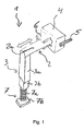
- FIG. 1 shows in the standing position the support leg 1 according to the invention with a first segment 2 and a second segment 3, which are arranged substantially perpendicular to each other. Furthermore, the support leg 1 has a bearing element 4, through which the first segment 2 protrudes.
- a bearing element 4 By in the FIG. 1 plotted double arrow indicates that the first segment 2 along its longitudinal axis relative to the Bearing element 4 is displaceable.
- a locking bolt 5 is provided on the bearing element 4.
- the bearing element 4 is attached to a container (not shown), for example, welded.
- the first segment 2 is formed in the illustrated embodiment as a round tube, so that in FIG. 1 visible portion 2a can be rotated or pivoted within the bearing element 4.
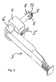
- the inventively provided portion 2b, which is formed against rotation, as well as the discernible on the bearing element 4 projection 6 are described below with reference to FIG. 2 explained in more detail.
- the first, round segment 2 merges at one of its ends into the essentially perpendicular thereto arranged second segment 3, which has a substantially rectangular cross-section in the illustrated embodiment. Due to a suitable connection between the round segment 2 and the rectangular segment 3, for example, a diagonal connecting both segments strut is not required. Alternatively to the illustration, an additional strut can be arranged after the positioning of the support leg 1 in the standing position with a suitable fastening device on the two segments 2, 3.
- the second segment 3 may comprise a plurality of telescopically intermeshing sub-pipes 3a and 3b which are displaceable and lockable in different height settings relative to one another in order to allow a height adjustment of the support leg 1.
- a foot part 7 is provided at the bottom to the bottom surface (not shown) facing sub-tube 3b.
- the foot part 7 has an externally threaded round tube 7a, which is engaged with a complementary internal thread (not shown) provided in the lower part tube 3b.
- the foot part 7 terminates with a base plate 7b.
- the locking element 5 is first to unlock. Subsequently, the first segment 2 is displaced along its longitudinal axis by a partial distance until the rotatable portion 2 a is located within the bearing element 4. Now, the support leg 1 can be pivoted such that the second segment 3 from the substantially vertical orientation ( FIG. 1 ) in the substantially horizontal orientation ( FIG. 2 ). Finally, the first segment 2 is moved further, so that the connection between the two segments 2, 3 enters the region of the projection 6. to Securing the transport position can be locked again by means of the locking element 5, the arrangement of the first segment 2 within the bearing element 4.
- the projection 6 is U-shaped.
- the opening of the U points in the direction of the longitudinal axis of the second segment 3 in the transport position. Due to the support of the connection of the two segments 2, 3 on the two legs of the U-shaped projection 6, the support leg 1 is secured in the transport position against rotation.
- FIG. 2 is the rotationally fixed portion 2b of the first segment 2 can be seen.
- a plurality of additional projections 8 to the segment 2
- this is deformed in the section 2b such that spans a substantially rectangular profile plane.
- the bearing element 4 has a complementary thereto inner profile. In this way, the second segment 2 is then mounted against rotation in the bearing element 4, when the section 2b is located in this.
- the support leg described above is particularly suitable for cargo and tank containers and can be welded to the container, for example, with the bearing element 4.
- the welding point can connect directly to the lower corner fittings of a container.
- the arrangement described above allows despite low or small installation depth a relatively large underride width with flared support legs.
- the support leg With the help of the telescopically formed sub-pipes 3 and the fine tuning by the thread assembly 7a, the support leg can be aligned horizontally. In the retracted state, the support legs are preferably flush with the outer dimensions of the standardized freight containers.
Landscapes
- Engineering & Computer Science (AREA)
- Mechanical Engineering (AREA)
- Details Of Rigid Or Semi-Rigid Containers (AREA)
- Auxiliary Devices For And Details Of Packaging Control (AREA)
- Pallets (AREA)
- Supplying Of Containers To The Packaging Station (AREA)
- Filling Or Discharging Of Gas Storage Vessels (AREA)
Abstract
Description
- Die Erfindung betrifft ein Stützbein für einen Tankcontainer oder einen für einen Tankcontainer bestimmten Tragrahmen mit einem ersten Segment und einem zweiten Segment, die insbesondere winklig miteinander verbunden sind, und mit einem Lagerelement, das zur Befestigung an dem Tankcontainer oder dem Tragrahmen vorgesehen ist und in welchem das erste Segment derart gelagert ist, dass das Stützbein von einer Standposition in eine Transportposition und zurück verschwenkbar ist.
- Derartige Stützbeine erlauben das Abstellen eines damit versehenen Tankcontainers oder Boxcontainers. Bei dem auf einer Transporteinheit angeordneten Container werden zunächst die Stützbeine aus einer Transportposition, in der die Stützbeine die Beförderung nicht behindernd angeordnet sind, in die Stützposition verschwenkt. In dieser Position kann die Transporteinheit unter dem Container fortbewegt werden und die Last des Containers wird von den Stützbeinen aufgenommen. Eine Strebe dient der Sicherung der Stützposition.
- Für eine Höhenverstellung der Stützbeine, um eine Anpassung an unterschiedliche Rampen-und Fahrzeughöhen nahezu stufenlos zu ermöglichen, ist aus der
WO 2004/002859 ein Teleskopteil aus mehreren ineinanderpassenden Aluminiumprofilen bekannt, die in einer gewünschten Position arretierbar sind. - Der Erfindung liegt die Aufgabe zu Grunde, eine Möglichkeit zu schaffen, ein kompaktes und stabiles Stützbein anzugeben, welches eine einfache Handhabung gestattet.
- Diese Aufgabe wird erfindungsgemäß mit einem Stützbein gemäß den Merkmalen des Anspruchs 1 gelöst. Die weitere Ausgestaltung der Erfindung ist den Unteransprüchen zu entnehmen.
- Bei einem Stützbein der eingangs beschriebenen Art ist erfindungsgemäß vorgesehen, dass das erste Segment in Richtung seiner Längsachse innerhalb des Lagerelements verschiebbar ist und einen ersten Abschnitt mit einem drehfesten Querschnittsprofil und einen zweiten Abschnitt aufweist, der derart vorgesehen ist, dass das erste Segment um die Längsachse drehbar ist. Aufgrund der Verschiebung kann sich entweder der erste Abschnitt mit einem drehfesten Querschnittsprofil oder der zweite, drehbare Abschnitt in dem Bereich des Lagerelements befinden. Mittels des drehfesten Abschnitts kann die Ausrichtung des Stützbeins in Bezug auf das Lagerelement arretiert werden und das Stützbein ist in dieser Position, beispielsweise der Stützposition, stabil gehalten. Um nun das Stützbein von der Stützposition in die Transportposition zu verschwenken, wird das Stützbein in Richtung der Längsachse des ersten Segments verschoben, sodass der Abschnitt mit dem drehfesten Querschnittsprofil aus dem Lagerelement heraus bewegt wird und der drehbare Abschnitt in diesen Bereich des Lagerelements gelangt. Das Stützbein kann nun verschwenkt werden. Dabei kann erfindungsgemäß auf eine Strebe zur Festlegung des Stützbeins in der Standposition verzichtet werden. Selbstverständlich kann eine solche Strebe, die beispielsweise mittels eines Bolzens an einer Durchbrechung des Stützbeins festlegbar ist, ergänzend angeordnet werden. Neben Tankcontainern und einem für diesen bestimmten Tragrahmen ist die Erfindung in vorteilhafter Weise auch bei Tank- oder Silowagen und bei Boxcontainern insbesondere mit einer Gesamtlast von bis zu 37 t einsetzbar.
- Die Segmente können zu einer Baueinheit insbesondere auch einteilig zusammengefasst sein. Bevorzugt sind das erste Segment und das zweite Segment im Wesentlichen senkrecht zueinander angeordnet. Auf diese Weise werden eine Platz sparende Bauform in Verbindung mit einer zuverlässigen Kraftübertragung aufgrund der Containerlast und ein stabiler Stand ermöglicht.
- Ein einfacher Aufbau und eine kostengünstige Herstellung werden dadurch erreicht, dass das erste Segment ein Rundrohr ist, das an dem, dem zweiten Segment gegenüberliegenden Ende durch zusätzlich aufgebrachtes, einen Vorsprung bildendes Material ein im Wesentlichen rechteckiges Außenprofil aufweist.
- Für eine möglichst spielfreie und stabile Lagerung des ersten Segments weist das Lagerelement ein zum rechteckigen Außenprofil des ersten Segments komplementäres Innenprofil auf.
- Um einen kompakten Gesamtaufbau auch in der Transportposition zu erreichen, weist das Lagerelement auf der dem zweiten Segment zugewandten Seite einen das erste Segment teilweise derart umfassenden Vorsprung auf, dass in der Transportposition der Vorsprung das zweite Segment im Bereich der Rohrverbindung abstützt.
- Für eine Sicherung der Längsverschiebung des ersten Segments ist an dem Lagerelement ein Verriegelungselement vorgesehen, beispielsweise ein Verriegelungsbolzen.
- Das Stützbein ist mit einer weiteren vorteilhaften Ausgestaltung, beispielsweise mit einer Höhenverstellung ausgestattet, bei der das zweite Segment mehrere teleskopartig ineinandergreifende Teilrohre aufweist. Die Festlegung der gewünschten axialen Position erfolgt dabei kraftschlüssig oder formschlüssig, beispielsweise mittels eines in eine von mehreren Ausnehmungen eingreifenden Steckbolzens.
- Ein stabiler Stand des Stützbeins wird dadurch erreicht, dass das zweite Segment ein im Wesentlichen rechteckiges Profil aufweist.
- Für eine nahezu stufenlose Höhenanpassung ist vorgesehen, dass das zweite Segment an dem der Rohrverbindung gegenüberliegenden Ende ein mit einem Außengewinde versehenes Fußteil aufweist.
- Aus Gewichtsgründen besteht zumindest ein Segment aus Aluminium.
- In vorteilhafter Weise ist ein Container mit mehreren erfindungsgemäßen Stützbeinen, beispielsweise mit vier Stützbeinen, versehen.
- Die Erfindung lässt verschiedene Ausführungsformen zu. Zur weiteren Verdeutlichung ihres Grundprinzips ist eine davon in den Zeichnungen beispielhaft dargestellt und wird nachfolgend detaillierter beschrieben. Diese zeigen in
- Fig. 1
- eine perspektivische Ansicht des erfindungsgemäßen Stützbeins in Standposition;
- Fig. 2
- eine perspektivische Ansicht des in
Figur 1 gezeigten Stützbeins in Transportposition. -
Figur 1 zeigt in der Standposition das erfindungsgemäße Stützbein 1 mit einem ersten Segment 2 und einem zweiten Segment 3, die im Wesentlichen senkrecht zueinander angeordnet sind. Ferner weist das Stützbein 1 ein Lagerelement 4 auf, durch welches das erste Segment 2 hindurchragt. Durch den in derFigur 1 eingezeichneten Doppelpfeil wird angedeutet, dass das erste Segment 2 entlang seiner Längsachse relativ zu dem Lagerelement 4 verschiebbar ist. Um ein unerwünschtes Verschieben bzw. Verrutschen des ersten Segments 2 zu verhindern, ist an dem Lagerelement 4 ein Verriegelungsbolzen 5 vorgesehen. Das Lagerelement 4 wird an einem Container (nicht dargestellt) befestigt, beispielsweise verschweißt. - Das erste Segment 2 ist in der dargestellten Ausführungsform als ein Rundrohr ausgebildet, sodass der in
Figur 1 sichtbare Abschnitt 2a innerhalb des Lagerelements 4 gedreht bzw. verschwenkt werden kann. Der erfindungsgemäß vorgesehene Abschnitt 2b, der verdrehsicher ausgebildet ist, sowie der an dem Lagerelement 4 erkennbare Vorsprung 6 werden nachfolgend unter Bezug aufFigur 2 näher erläutert. - Das erste, runde Segment 2 geht an einem seiner Enden in das im Wesentlich senkrecht dazu angeordnete zweite Segment 3 über, das in dem dargestellten Ausführungsbeispiel einen im Wesentlichen rechteckigen Querschnitt aufweist. Aufgrund einer geeigneten Verbindung zwischen dem runden Segment 2 und dem rechteckigen Segment 3 ist eine beispielsweise diagonal beide Segmente verbindende Strebe nicht erforderlich. Alternativ zu der Darstellung kann eine zusätzliche Strebe nach der Positionierung des Stützbeines 1 in die Standposition mit einer geeigneten Befestigungseinrichtung an den beiden Segmenten 2, 3 angeordnet werden.
- Das zweite Segment 3 kann wie gezeigt mehrere teleskopartig ineinandergreifende Teilrohre 3a und 3b aufweisen, die in verschiedenen Höheneinstellungen relativ zueinander verschieb-und arretierbar sind, um eine Höhenanpassung des Stützbeins 1 zu ermöglichen. Am unteren zur Bodenfläche (nicht dargestellt) weisenden Teilrohr 3b ist ein Fußteil 7 vorgesehen. Das Fußteil 7 weist ein mit einem Außengewinde versehenes Rundrohr 7a auf, das mit einem in dem unteren Teilrohr 3b vorgesehenen komplementären Innengewinde (nicht dargestellt) im Eingriff ist. Für eine höhere Stabilität schließt das Fußteil 7 mit einer Standplatte 7b ab.
- Um das Stützbein 1 von der Standposition der
Figur 1 in die Transportposition derFigur 2 zu verschwenken, ist zunächst das Verriegelungselement 5 zu entriegeln. Anschließend wird das erste Segment 2 entlang seiner Längsachse um eine Teilstrecke verschoben, bis sich der drehbare Abschnitt 2a innerhalb des Lagerelements 4 befindet. Nun kann das Stützbein 1 derart verschwenkt werden, dass das zweite Segment 3 aus der im Wesentlichen vertikalen Ausrichtung (Figur 1 ) in die im Wesentlichen horizontale Ausrichtung (Figur 2 ) gelangt. Abschließend wird das erste Segment 2 weiter verschoben, sodass die Verbindung zwischen den beiden Segmenten 2, 3 in den Bereich des Vorsprungs 6 gelangt. Zur Sicherung der Transportposition kann erneut mittels des Verriegelungselements 5 die Anordnung des ersten Segments 2 innerhalb des Lagerelements 4 arretiert werden. - Der Vorsprung 6 ist u-förmig ausgebildet. Die Öffnung des U weist in die Richtung der Längsachse des zweiten Segments 3 in der Transportposition. Aufgrund der Abstützung der Verbindung der beiden Segmente 2, 3 an den beiden Schenkeln des u-förmigen Vorsprungs 6 ist das Stützbein 1 in der Transportposition gegen eine Verdrehung gesichert.
- In
Figur 2 ist der drehfeste Abschnitt 2b des ersten Segments 2 zu erkennen. Durch Anbringen mehrerer zusätzlicher Vorsprünge 8 an das Segment 2 wird dieses in dem Abschnitt 2b derart umgeformt, dass eine im Wesentlichen rechteckige Profilebene aufspannt. Das Lagerelement 4 weist ein hierzu komplementäres Innenprofil auf. Auf diese Weise ist das zweite Segment 2 dann in dem Lagerelement 4 verdrehsicher gelagert, wenn sich der Abschnitt 2b in diesem befindet. - Das vorstehend beschriebene Stützbein ist insbesondere für Fracht- und Tankcontainer geeignet und kann beispielsweise mit dem Lagerelement 4 an dem Container angeschweißt sein. Der Einschweißpunkt kann sich hierbei unmittelbar an den unteren Eckbeschlägen eines Containers anschließen. Die vorstehend beschriebene Anordnung ermöglicht trotz geringer bzw. kleiner Einbautiefe eine relativ große Unterfahrbreite bei ausgestellten Stützbeinen. Mit Hilfe der teleskopartig ausgebildeten Teilrohre 3 und der Feinabstimmung durch die Gewindeanordnung 7a kann das Stützbein waagerecht ausgerichtet werden. Im eingeschobenen Zustand sind die Stützbeine bevorzugt bündig mit den Außenmaßen der genormten Frachtcontainer.
Claims (13)
- Stützbein (1) für einen Container oder einen für einen Container bestimmten Tragrahmen mit einem ersten Segment (2) und einem zweiten Segment (3), die insbesondere winklig miteinander verbunden sind, und mit einem Lagerelement (4), das zur Befestigung an dem Container oder dem Tragrahmen vorgesehen ist und in welchem das erste Segment (2) derart gelagert ist, dass das Stützbein (1) von einer Standposition in eine Transportposition und zurück verschwenkbar ist, dadurch gekennzeichnet, dass das erste Segment (2) relativ zu dem Lagerelement (4) axial verschiebbar ist und in Richtung seiner Längsachse einen ersten Abschnitt (2b) mit einem drehfesten Querschnittsprofil und einen zweiten, um die Längsachse zumindest eingeschränkt schwenkbaren Abschnitt (2a) aufweist.
- Stützbein (1) nach Anspruch 1, dadurch gekennzeichnet, dass das erste Segment (2) und das zweite Segment (3) im Wesentlichen senkrecht zueinander angeordnet sind.
- Stützbein (1) nach den Ansprüchen 1 oder 2, dadurch gekennzeichnet, dass der Abschnitt (2a) eine rotationssymmetrische Querschnittsform aufweist.
- Stützbein (1) nach zumindest einem der vorhergehenden Ansprüche, dadurch gekennzeichnet, dass zumindest das erste Segment (2) ein Rohr, insbesondere Rundrohr aufweist.
- Stützbein (1) nach zumindest einem der vorhergehenden Ansprüche, dadurch gekennzeichnet, dass das drehfeste Querschnittsprofil des ersten Abschnitts (2b) an einem dem zweiten Segment (3) gegenüberliegenden Endbereich einen Vorsprung (8), insbesondere eine eckige Querschnittsform aufweist.
- Stützbein (1) nach zumindest einem der vorhergehenden Ansprüche, dadurch gekennzeichnet, dass das Lagerelement (4) ein zum rechteckigen Außenprofil des ersten Segments (2) komplementäres Innenprofil aufweist.
- Stützbein (1) nach zumindest einem der vorhergehenden Ansprüche, dadurch gekennzeichnet, dass das Stützbein (1) einen dem zweiten Segment (3) zugewandten, das erste Segment (2) teilweise derart umfassenden Vorsprung (6) aufweist, das in der Transportposition der Vorsprung (6) das zweite Segment (3) insbesondere im Bereich der Rohrverbindung abstützt.
- Stützbein (1) nach zumindest einem der vorhergehenden Ansprüche, dadurch gekennzeichnet, dass das Lagerelement (4) ein Verriegelungselement (5) aufweist.
- Stützbein (1) nach zumindest einem der vorhergehenden Ansprüche, dadurch gekennzeichnet, dass das zweite Segment (3) mehrere teleskopartig ineinandergreifende Teilrohre (3a, 3b) aufweist.
- Stützbein (1) nach zumindest einem der vorhergehenden Ansprüche, dadurch gekennzeichnet, dass das zweite Segment (3) ein im Wesentlichen rechteckiges Profil aufweist.
- Stützbein (1) nach zumindest einem der vorhergehenden Ansprüche, dadurch gekennzeichnet, dass das zweite Segment (3) an dem der Rohrverbindung gegenüberliegenden Ende ein mit einem Außengewinde versehenes Fußteil (7) aufweist.
- Stützbein (1) nach zumindest einem der vorhergehenden Ansprüche, dadurch gekennzeichnet, dass das Stützbein (1) als einen wesentlichen Materialbestandteil Aluminium aufweist.
- Container oder ein für einen Container bestimmter Tragrahmen mit mehreren Stützbeinen nach zumindest einem der vorstehenden Ansprüche.
Applications Claiming Priority (1)
| Application Number | Priority Date | Filing Date | Title |
|---|---|---|---|
| DE102007031838A DE102007031838A1 (de) | 2007-07-08 | 2007-07-08 | Stützbein, schwenkbar und teleskopierbar, für Box- und Tankcontainer |
Publications (2)
| Publication Number | Publication Date |
|---|---|
| EP2014581A1 true EP2014581A1 (de) | 2009-01-14 |
| EP2014581B1 EP2014581B1 (de) | 2011-01-19 |
Family
ID=39772726
Family Applications (1)
| Application Number | Title | Priority Date | Filing Date |
|---|---|---|---|
| EP08002114A Not-in-force EP2014581B1 (de) | 2007-07-08 | 2008-02-05 | Stützbein für Container |
Country Status (3)
| Country | Link |
|---|---|
| EP (1) | EP2014581B1 (de) |
| AT (1) | ATE495986T1 (de) |
| DE (2) | DE102007031838A1 (de) |
Cited By (1)
| Publication number | Priority date | Publication date | Assignee | Title |
|---|---|---|---|---|
| CH711456A1 (de) * | 2015-08-28 | 2017-02-28 | Aregger Kurt | Abstellvorrichtung für Grossraumbehälter. |
Citations (7)
| Publication number | Priority date | Publication date | Assignee | Title |
|---|---|---|---|---|
| DE1900560A1 (de) * | 1968-01-11 | 1969-07-31 | Doornes Aanhangwagenfab | Sattelauflieger |
| DE3407668A1 (de) * | 1984-03-01 | 1985-09-12 | Bier-Drive AG, Chur | Gestell zur aufnahme eines liegenden zylinderfoermigen tanks |
| EP1038801A1 (de) * | 1999-03-26 | 2000-09-27 | Oy Närko Ab | Behälterstützbein |
| DE20120996U1 (de) * | 2001-05-12 | 2002-06-20 | Wecon GmbH Nutzfahrzeuge-Container-Technik, 59387 Ascheberg | Stützbeinhalterung für einen Wechselbehälter |
| FR2822925A1 (fr) * | 2001-03-28 | 2002-10-04 | Gerard Grosse | Dispositif d'appui pour caisse amovible reposant sur un plateau, et plateau pourvu d'au moin quatre de ces dispositifs |
| DE20312199U1 (de) * | 2002-08-10 | 2003-11-13 | Wecon GmbH Nutzfahrzeuge-Container-Technik, 59387 Ascheberg | Stützbeinhalterung, insbesondere für einen Wechselbehälter |
| WO2004002859A2 (de) | 2002-06-12 | 2004-01-08 | Hugo Siebert | Teleskopteil aus aluminium für stützlasten |
-
2007
- 2007-07-08 DE DE102007031838A patent/DE102007031838A1/de not_active Withdrawn
-
2008
- 2008-02-05 EP EP08002114A patent/EP2014581B1/de not_active Not-in-force
- 2008-02-05 DE DE502008002363T patent/DE502008002363D1/de active Active
- 2008-02-05 AT AT08002114T patent/ATE495986T1/de active
Patent Citations (7)
| Publication number | Priority date | Publication date | Assignee | Title |
|---|---|---|---|---|
| DE1900560A1 (de) * | 1968-01-11 | 1969-07-31 | Doornes Aanhangwagenfab | Sattelauflieger |
| DE3407668A1 (de) * | 1984-03-01 | 1985-09-12 | Bier-Drive AG, Chur | Gestell zur aufnahme eines liegenden zylinderfoermigen tanks |
| EP1038801A1 (de) * | 1999-03-26 | 2000-09-27 | Oy Närko Ab | Behälterstützbein |
| FR2822925A1 (fr) * | 2001-03-28 | 2002-10-04 | Gerard Grosse | Dispositif d'appui pour caisse amovible reposant sur un plateau, et plateau pourvu d'au moin quatre de ces dispositifs |
| DE20120996U1 (de) * | 2001-05-12 | 2002-06-20 | Wecon GmbH Nutzfahrzeuge-Container-Technik, 59387 Ascheberg | Stützbeinhalterung für einen Wechselbehälter |
| WO2004002859A2 (de) | 2002-06-12 | 2004-01-08 | Hugo Siebert | Teleskopteil aus aluminium für stützlasten |
| DE20312199U1 (de) * | 2002-08-10 | 2003-11-13 | Wecon GmbH Nutzfahrzeuge-Container-Technik, 59387 Ascheberg | Stützbeinhalterung, insbesondere für einen Wechselbehälter |
Cited By (1)
| Publication number | Priority date | Publication date | Assignee | Title |
|---|---|---|---|---|
| CH711456A1 (de) * | 2015-08-28 | 2017-02-28 | Aregger Kurt | Abstellvorrichtung für Grossraumbehälter. |
Also Published As
| Publication number | Publication date |
|---|---|
| ATE495986T1 (de) | 2011-02-15 |
| DE502008002363D1 (de) | 2011-03-03 |
| EP2014581B1 (de) | 2011-01-19 |
| DE102007031838A1 (de) | 2009-01-15 |
Similar Documents
| Publication | Publication Date | Title |
|---|---|---|
| DE102009040200B4 (de) | Transportvorrichtung für ein längliches Objekt | |
| EP0597406B1 (de) | Höhenverstellbare Hubstütze, vorzugsweise für Wohnmobile | |
| EP3697983B1 (de) | Stütze zum abstützen eines bauwerkbereichs | |
| DE102018221183B3 (de) | Justierbeschlag und Tragsystem für Solarmodule | |
| EP2698296A2 (de) | Längenverstellbares Teleskoprohr | |
| EP2698295B1 (de) | Längenverstellbares Teleskoprohr, Stützwinde und Montageverfahren | |
| EP2567865B1 (de) | Sicherungsvorrichtung für den Transport einer schweren Last | |
| EP2420406B1 (de) | Vorrichtung zum Sichern von Ladung auf einer Ladefläche eines Fahrzeugaufbaus | |
| EP3224417B1 (de) | Transportable barriere für eine gedrängesperre | |
| WO2021105221A1 (de) | Rohrverbindungsstruktur und möbelbausatz | |
| EP2014581B1 (de) | Stützbein für Container | |
| DE9405344U1 (de) | Haltevorrichtung | |
| DE102008048581B4 (de) | Vorrichtung zum Halten und Sichern von Ladegut, insbesondere in Form einer Sperrstange | |
| DE102005028525A1 (de) | Vorrichtung zur Sicherung einer Ladung | |
| DE3152360C2 (de) | ||
| EP2540567B1 (de) | Befestigungssystem für dne Transport einer schweren Last auf einer Transportoberfläche | |
| EP3571108B1 (de) | Rahmen eines kinderwagens | |
| AT518917B1 (de) | Absturzsicherung | |
| EP1808335A1 (de) | Geländeranordnung | |
| EP4263977B1 (de) | Rahmengestell mit einem mastbock zur lagerung eines dickstoffverteilermasts | |
| WO2015197576A2 (de) | Fahrmischerpumpe | |
| DE202005016808U1 (de) | Stützfuß für Hebebrücken | |
| EP0183261B1 (de) | Hochdachträger-Element für ein Kraftfahrzeug | |
| DE4304555C1 (de) | Verbindungsstück zur klemmenden Verbindung zweier senkrecht zueinander angeordneter Profilstücke eines Fördergestells | |
| EP3290307B1 (de) | Montagevorrichtung und anhänger |
Legal Events
| Date | Code | Title | Description |
|---|---|---|---|
| PUAI | Public reference made under article 153(3) epc to a published international application that has entered the european phase |
Free format text: ORIGINAL CODE: 0009012 |
|
| AK | Designated contracting states |
Kind code of ref document: A1 Designated state(s): AT BE BG CH CY CZ DE DK EE ES FI FR GB GR HR HU IE IS IT LI LT LU LV MC MT NL NO PL PT RO SE SI SK TR |
|
| AX | Request for extension of the european patent |
Extension state: AL BA MK RS |
|
| 17P | Request for examination filed |
Effective date: 20090714 |
|
| 17Q | First examination report despatched |
Effective date: 20090806 |
|
| AKX | Designation fees paid |
Designated state(s): AT BE BG CH CY CZ DE DK EE ES FI FR GB GR HR HU IE IS IT LI LT LU LV MC MT NL NO PL PT RO SE SI SK TR |
|
| GRAP | Despatch of communication of intention to grant a patent |
Free format text: ORIGINAL CODE: EPIDOSNIGR1 |
|
| GRAA | (expected) grant |
Free format text: ORIGINAL CODE: 0009210 |
|
| GRAS | Grant fee paid |
Free format text: ORIGINAL CODE: EPIDOSNIGR3 |
|
| AK | Designated contracting states |
Kind code of ref document: B1 Designated state(s): AT BE BG CH CY CZ DE DK EE ES FI FR GB GR HR HU IE IS IT LI LT LU LV MC MT NL NO PL PT RO SE SI SK TR |
|
| REG | Reference to a national code |
Ref country code: GB Ref legal event code: FG4D Free format text: NOT ENGLISH |
|
| REG | Reference to a national code |
Ref country code: CH Ref legal event code: EP |
|
| REG | Reference to a national code |
Ref country code: IE Ref legal event code: FG4D Free format text: LANGUAGE OF EP DOCUMENT: GERMAN |
|
| REF | Corresponds to: |
Ref document number: 502008002363 Country of ref document: DE Date of ref document: 20110303 Kind code of ref document: P |
|
| REG | Reference to a national code |
Ref country code: DE Ref legal event code: R096 Ref document number: 502008002363 Country of ref document: DE Effective date: 20110303 |
|
| PGFP | Annual fee paid to national office [announced via postgrant information from national office to epo] |
Ref country code: IE Payment date: 20110216 Year of fee payment: 4 |
|
| REG | Reference to a national code |
Ref country code: NL Ref legal event code: T3 |
|
| REG | Reference to a national code |
Ref country code: SE Ref legal event code: TRGR |
|
| PGFP | Annual fee paid to national office [announced via postgrant information from national office to epo] |
Ref country code: FR Payment date: 20110301 Year of fee payment: 4 Ref country code: NL Payment date: 20110225 Year of fee payment: 4 |
|
| LTIE | Lt: invalidation of european patent or patent extension |
Effective date: 20110119 |
|
| PG25 | Lapsed in a contracting state [announced via postgrant information from national office to epo] |
Ref country code: LT Free format text: LAPSE BECAUSE OF FAILURE TO SUBMIT A TRANSLATION OF THE DESCRIPTION OR TO PAY THE FEE WITHIN THE PRESCRIBED TIME-LIMIT Effective date: 20110119 Ref country code: LV Free format text: LAPSE BECAUSE OF FAILURE TO SUBMIT A TRANSLATION OF THE DESCRIPTION OR TO PAY THE FEE WITHIN THE PRESCRIBED TIME-LIMIT Effective date: 20110119 Ref country code: NO Free format text: LAPSE BECAUSE OF FAILURE TO SUBMIT A TRANSLATION OF THE DESCRIPTION OR TO PAY THE FEE WITHIN THE PRESCRIBED TIME-LIMIT Effective date: 20110419 Ref country code: PT Free format text: LAPSE BECAUSE OF FAILURE TO SUBMIT A TRANSLATION OF THE DESCRIPTION OR TO PAY THE FEE WITHIN THE PRESCRIBED TIME-LIMIT Effective date: 20110519 Ref country code: GR Free format text: LAPSE BECAUSE OF FAILURE TO SUBMIT A TRANSLATION OF THE DESCRIPTION OR TO PAY THE FEE WITHIN THE PRESCRIBED TIME-LIMIT Effective date: 20110420 Ref country code: HR Free format text: LAPSE BECAUSE OF FAILURE TO SUBMIT A TRANSLATION OF THE DESCRIPTION OR TO PAY THE FEE WITHIN THE PRESCRIBED TIME-LIMIT Effective date: 20110119 Ref country code: ES Free format text: LAPSE BECAUSE OF FAILURE TO SUBMIT A TRANSLATION OF THE DESCRIPTION OR TO PAY THE FEE WITHIN THE PRESCRIBED TIME-LIMIT Effective date: 20110430 Ref country code: IS Free format text: LAPSE BECAUSE OF FAILURE TO SUBMIT A TRANSLATION OF THE DESCRIPTION OR TO PAY THE FEE WITHIN THE PRESCRIBED TIME-LIMIT Effective date: 20110519 |
|
| PGFP | Annual fee paid to national office [announced via postgrant information from national office to epo] |
Ref country code: BE Payment date: 20110221 Year of fee payment: 4 |
|
| PG25 | Lapsed in a contracting state [announced via postgrant information from national office to epo] |
Ref country code: SI Free format text: LAPSE BECAUSE OF FAILURE TO SUBMIT A TRANSLATION OF THE DESCRIPTION OR TO PAY THE FEE WITHIN THE PRESCRIBED TIME-LIMIT Effective date: 20110119 Ref country code: CY Free format text: LAPSE BECAUSE OF FAILURE TO SUBMIT A TRANSLATION OF THE DESCRIPTION OR TO PAY THE FEE WITHIN THE PRESCRIBED TIME-LIMIT Effective date: 20110119 Ref country code: PL Free format text: LAPSE BECAUSE OF FAILURE TO SUBMIT A TRANSLATION OF THE DESCRIPTION OR TO PAY THE FEE WITHIN THE PRESCRIBED TIME-LIMIT Effective date: 20110119 Ref country code: FI Free format text: LAPSE BECAUSE OF FAILURE TO SUBMIT A TRANSLATION OF THE DESCRIPTION OR TO PAY THE FEE WITHIN THE PRESCRIBED TIME-LIMIT Effective date: 20110119 Ref country code: BG Free format text: LAPSE BECAUSE OF FAILURE TO SUBMIT A TRANSLATION OF THE DESCRIPTION OR TO PAY THE FEE WITHIN THE PRESCRIBED TIME-LIMIT Effective date: 20110419 |
|
| PG25 | Lapsed in a contracting state [announced via postgrant information from national office to epo] |
Ref country code: MC Free format text: LAPSE BECAUSE OF NON-PAYMENT OF DUE FEES Effective date: 20110228 |
|
| RAP2 | Party data changed (patent owner data changed or rights of a patent transferred) |
Owner name: CONTAINER MASTER PROJEKT GMBH |
|
| PG25 | Lapsed in a contracting state [announced via postgrant information from national office to epo] |
Ref country code: EE Free format text: LAPSE BECAUSE OF FAILURE TO SUBMIT A TRANSLATION OF THE DESCRIPTION OR TO PAY THE FEE WITHIN THE PRESCRIBED TIME-LIMIT Effective date: 20110119 Ref country code: DK Free format text: LAPSE BECAUSE OF FAILURE TO SUBMIT A TRANSLATION OF THE DESCRIPTION OR TO PAY THE FEE WITHIN THE PRESCRIBED TIME-LIMIT Effective date: 20110119 |
|
| PLBE | No opposition filed within time limit |
Free format text: ORIGINAL CODE: 0009261 |
|
| STAA | Information on the status of an ep patent application or granted ep patent |
Free format text: STATUS: NO OPPOSITION FILED WITHIN TIME LIMIT |
|
| PG25 | Lapsed in a contracting state [announced via postgrant information from national office to epo] |
Ref country code: RO Free format text: LAPSE BECAUSE OF FAILURE TO SUBMIT A TRANSLATION OF THE DESCRIPTION OR TO PAY THE FEE WITHIN THE PRESCRIBED TIME-LIMIT Effective date: 20110119 Ref country code: CZ Free format text: LAPSE BECAUSE OF FAILURE TO SUBMIT A TRANSLATION OF THE DESCRIPTION OR TO PAY THE FEE WITHIN THE PRESCRIBED TIME-LIMIT Effective date: 20110119 Ref country code: SK Free format text: LAPSE BECAUSE OF FAILURE TO SUBMIT A TRANSLATION OF THE DESCRIPTION OR TO PAY THE FEE WITHIN THE PRESCRIBED TIME-LIMIT Effective date: 20110119 |
|
| RAP2 | Party data changed (patent owner data changed or rights of a patent transferred) |
Owner name: GWG VERWALTUNGS GMBH |
|
| 26N | No opposition filed |
Effective date: 20111020 |
|
| PG25 | Lapsed in a contracting state [announced via postgrant information from national office to epo] |
Ref country code: IT Free format text: LAPSE BECAUSE OF FAILURE TO SUBMIT A TRANSLATION OF THE DESCRIPTION OR TO PAY THE FEE WITHIN THE PRESCRIBED TIME-LIMIT Effective date: 20110119 Ref country code: MT Free format text: LAPSE BECAUSE OF FAILURE TO SUBMIT A TRANSLATION OF THE DESCRIPTION OR TO PAY THE FEE WITHIN THE PRESCRIBED TIME-LIMIT Effective date: 20110119 |
|
| REG | Reference to a national code |
Ref country code: DE Ref legal event code: R097 Ref document number: 502008002363 Country of ref document: DE Effective date: 20111020 |
|
| BERE | Be: lapsed |
Owner name: CMP CONTAINER MASTER PROJEKT G.M.B.H. Effective date: 20120228 |
|
| REG | Reference to a national code |
Ref country code: NL Ref legal event code: V1 Effective date: 20120901 |
|
| REG | Reference to a national code |
Ref country code: CH Ref legal event code: PL |
|
| GBPC | Gb: european patent ceased through non-payment of renewal fee |
Effective date: 20120205 |
|
| PG25 | Lapsed in a contracting state [announced via postgrant information from national office to epo] |
Ref country code: SE Free format text: LAPSE BECAUSE OF NON-PAYMENT OF DUE FEES Effective date: 20120206 Ref country code: CH Free format text: LAPSE BECAUSE OF NON-PAYMENT OF DUE FEES Effective date: 20120229 Ref country code: LI Free format text: LAPSE BECAUSE OF NON-PAYMENT OF DUE FEES Effective date: 20120229 |
|
| REG | Reference to a national code |
Ref country code: IE Ref legal event code: MM4A |
|
| REG | Reference to a national code |
Ref country code: FR Ref legal event code: ST Effective date: 20121031 |
|
| PG25 | Lapsed in a contracting state [announced via postgrant information from national office to epo] |
Ref country code: BE Free format text: LAPSE BECAUSE OF NON-PAYMENT OF DUE FEES Effective date: 20120228 |
|
| PG25 | Lapsed in a contracting state [announced via postgrant information from national office to epo] |
Ref country code: NL Free format text: LAPSE BECAUSE OF NON-PAYMENT OF DUE FEES Effective date: 20120901 Ref country code: FR Free format text: LAPSE BECAUSE OF NON-PAYMENT OF DUE FEES Effective date: 20120229 Ref country code: IE Free format text: LAPSE BECAUSE OF NON-PAYMENT OF DUE FEES Effective date: 20120205 Ref country code: GB Free format text: LAPSE BECAUSE OF NON-PAYMENT OF DUE FEES Effective date: 20120205 |
|
| PG25 | Lapsed in a contracting state [announced via postgrant information from national office to epo] |
Ref country code: LU Free format text: LAPSE BECAUSE OF NON-PAYMENT OF DUE FEES Effective date: 20110205 |
|
| PG25 | Lapsed in a contracting state [announced via postgrant information from national office to epo] |
Ref country code: HU Free format text: LAPSE BECAUSE OF FAILURE TO SUBMIT A TRANSLATION OF THE DESCRIPTION OR TO PAY THE FEE WITHIN THE PRESCRIBED TIME-LIMIT Effective date: 20110119 Ref country code: TR Free format text: LAPSE BECAUSE OF NON-PAYMENT OF DUE FEES Effective date: 20120205 |
|
| REG | Reference to a national code |
Ref country code: DE Ref legal event code: R119 Ref document number: 502008002363 Country of ref document: DE Effective date: 20130903 |
|
| REG | Reference to a national code |
Ref country code: DE Ref legal event code: R073 Ref document number: 502008002363 Country of ref document: DE |
|
| REG | Reference to a national code |
Ref country code: DE Ref legal event code: R074 Ref document number: 502008002363 Country of ref document: DE |
|
| PG25 | Lapsed in a contracting state [announced via postgrant information from national office to epo] |
Ref country code: DE Free format text: LAPSE BECAUSE OF NON-PAYMENT OF DUE FEES Effective date: 20130903 |
|
| REG | Reference to a national code |
Ref country code: DE Ref legal event code: R074 Ref document number: 502008002363 Country of ref document: DE Effective date: 20140121 Ref country code: DE Ref legal event code: R074 Ref document number: 502008002363 Country of ref document: DE Effective date: 20140124 |
|
| REG | Reference to a national code |
Ref country code: AT Ref legal event code: MM01 Ref document number: 495986 Country of ref document: AT Kind code of ref document: T Effective date: 20130205 |
|
| PGFP | Annual fee paid to national office [announced via postgrant information from national office to epo] |
Ref country code: DE Payment date: 20140207 Year of fee payment: 7 |
|
| PGRI | Patent reinstated in contracting state [announced from national office to epo] |
Ref country code: DE Effective date: 20140121 |
|
| PG25 | Lapsed in a contracting state [announced via postgrant information from national office to epo] |
Ref country code: AT Free format text: LAPSE BECAUSE OF NON-PAYMENT OF DUE FEES Effective date: 20130205 |
|
| REG | Reference to a national code |
Ref country code: DE Ref legal event code: R119 Ref document number: 502008002363 Country of ref document: DE |
|
| PG25 | Lapsed in a contracting state [announced via postgrant information from national office to epo] |
Ref country code: DE Free format text: LAPSE BECAUSE OF NON-PAYMENT OF DUE FEES Effective date: 20150901 |