EP2014573B1 - Mehrfachverpackung und Rohling dafür - Google Patents
Mehrfachverpackung und Rohling dafür Download PDFInfo
- Publication number
- EP2014573B1 EP2014573B1 EP08101665A EP08101665A EP2014573B1 EP 2014573 B1 EP2014573 B1 EP 2014573B1 EP 08101665 A EP08101665 A EP 08101665A EP 08101665 A EP08101665 A EP 08101665A EP 2014573 B1 EP2014573 B1 EP 2014573B1
- Authority
- EP
- European Patent Office
- Prior art keywords
- articles
- panel
- package
- blank
- insert
- Prior art date
- Legal status (The legal status is an assumption and is not a legal conclusion. Google has not performed a legal analysis and makes no representation as to the accuracy of the status listed.)
- Not-in-force
Links
- 239000002131 composite material Substances 0.000 title claims description 16
- 238000004806 packaging method and process Methods 0.000 title description 8
- 239000000463 material Substances 0.000 claims description 46
- 125000006850 spacer group Chemical group 0.000 claims description 23
- 239000010410 layer Substances 0.000 description 25
- 239000011087 paperboard Substances 0.000 description 11
- 239000000123 paper Substances 0.000 description 4
- 239000002355 dual-layer Substances 0.000 description 3
- 238000010276 construction Methods 0.000 description 2
- 230000008878 coupling Effects 0.000 description 2
- 238000010168 coupling process Methods 0.000 description 2
- 238000005859 coupling reaction Methods 0.000 description 2
- 230000013011 mating Effects 0.000 description 2
- 210000003739 neck Anatomy 0.000 description 2
- 230000015572 biosynthetic process Effects 0.000 description 1
- 239000011111 cardboard Substances 0.000 description 1
- 230000006835 compression Effects 0.000 description 1
- 238000007906 compression Methods 0.000 description 1
- 238000006073 displacement reaction Methods 0.000 description 1
- 230000000694 effects Effects 0.000 description 1
- 230000000977 initiatory effect Effects 0.000 description 1
- 238000000034 method Methods 0.000 description 1
- 230000035515 penetration Effects 0.000 description 1
- 239000004033 plastic Substances 0.000 description 1
- 230000001737 promoting effect Effects 0.000 description 1
- 229920001169 thermoplastic Polymers 0.000 description 1
- 239000004416 thermosoftening plastic Substances 0.000 description 1
Images














Classifications
-
- B—PERFORMING OPERATIONS; TRANSPORTING
- B65—CONVEYING; PACKING; STORING; HANDLING THIN OR FILAMENTARY MATERIAL
- B65D—CONTAINERS FOR STORAGE OR TRANSPORT OF ARTICLES OR MATERIALS, e.g. BAGS, BARRELS, BOTTLES, BOXES, CANS, CARTONS, CRATES, DRUMS, JARS, TANKS, HOPPERS, FORWARDING CONTAINERS; ACCESSORIES, CLOSURES, OR FITTINGS THEREFOR; PACKAGING ELEMENTS; PACKAGES
- B65D71/00—Bundles of articles held together by packaging elements for convenience of storage or transport, e.g. portable segregating carrier for plural receptacles such as beer cans or pop bottles; Bales of material
- B65D71/06—Packaging elements holding or encircling completely or almost completely the bundle of articles, e.g. wrappers
- B65D71/08—Wrappers shrunk by heat or under tension, e.g. stretch films or films tensioned by compressed articles
- B65D71/10—Wrappers shrunk by heat or under tension, e.g. stretch films or films tensioned by compressed articles and provided with inserts
-
- B—PERFORMING OPERATIONS; TRANSPORTING
- B65—CONVEYING; PACKING; STORING; HANDLING THIN OR FILAMENTARY MATERIAL
- B65D—CONTAINERS FOR STORAGE OR TRANSPORT OF ARTICLES OR MATERIALS, e.g. BAGS, BARRELS, BOTTLES, BOXES, CANS, CARTONS, CRATES, DRUMS, JARS, TANKS, HOPPERS, FORWARDING CONTAINERS; ACCESSORIES, CLOSURES, OR FITTINGS THEREFOR; PACKAGING ELEMENTS; PACKAGES
- B65D2571/00—Bundles of articles held together by packaging elements for convenience of storage or transport, e.g. portable segregating carrier for plural receptacles such as beer cans, pop bottles; Bales of material
- B65D2571/00123—Bundling wrappers or trays
- B65D2571/00129—Wrapper locking means
- B65D2571/00135—Wrapper locking means integral with the wrapper
- B65D2571/00148—Wrapper locking means integral with the wrapper heat sealede or welded
-
- B—PERFORMING OPERATIONS; TRANSPORTING
- B65—CONVEYING; PACKING; STORING; HANDLING THIN OR FILAMENTARY MATERIAL
- B65D—CONTAINERS FOR STORAGE OR TRANSPORT OF ARTICLES OR MATERIALS, e.g. BAGS, BARRELS, BOTTLES, BOXES, CANS, CARTONS, CRATES, DRUMS, JARS, TANKS, HOPPERS, FORWARDING CONTAINERS; ACCESSORIES, CLOSURES, OR FITTINGS THEREFOR; PACKAGING ELEMENTS; PACKAGES
- B65D2571/00—Bundles of articles held together by packaging elements for convenience of storage or transport, e.g. portable segregating carrier for plural receptacles such as beer cans, pop bottles; Bales of material
- B65D2571/00123—Bundling wrappers or trays
- B65D2571/00246—Locating elements for the contents
- B65D2571/00253—Locating elements for the contents integral with the wrapper
- B65D2571/00302—Locating elements for the contents integral with the wrapper consisting of an inward deformation of at least a wall, e.g. embossed, keels
-
- B—PERFORMING OPERATIONS; TRANSPORTING
- B65—CONVEYING; PACKING; STORING; HANDLING THIN OR FILAMENTARY MATERIAL
- B65D—CONTAINERS FOR STORAGE OR TRANSPORT OF ARTICLES OR MATERIALS, e.g. BAGS, BARRELS, BOTTLES, BOXES, CANS, CARTONS, CRATES, DRUMS, JARS, TANKS, HOPPERS, FORWARDING CONTAINERS; ACCESSORIES, CLOSURES, OR FITTINGS THEREFOR; PACKAGING ELEMENTS; PACKAGES
- B65D2571/00—Bundles of articles held together by packaging elements for convenience of storage or transport, e.g. portable segregating carrier for plural receptacles such as beer cans, pop bottles; Bales of material
- B65D2571/00123—Bundling wrappers or trays
- B65D2571/00333—Partitions, i.e. elements contacting a major part of each aarticle or extending across the whole length of the wrapper
- B65D2571/00339—Partitions, i.e. elements contacting a major part of each aarticle or extending across the whole length of the wrapper extending from the upper or lower wall
-
- B—PERFORMING OPERATIONS; TRANSPORTING
- B65—CONVEYING; PACKING; STORING; HANDLING THIN OR FILAMENTARY MATERIAL
- B65D—CONTAINERS FOR STORAGE OR TRANSPORT OF ARTICLES OR MATERIALS, e.g. BAGS, BARRELS, BOTTLES, BOXES, CANS, CARTONS, CRATES, DRUMS, JARS, TANKS, HOPPERS, FORWARDING CONTAINERS; ACCESSORIES, CLOSURES, OR FITTINGS THEREFOR; PACKAGING ELEMENTS; PACKAGES
- B65D2571/00—Bundles of articles held together by packaging elements for convenience of storage or transport, e.g. portable segregating carrier for plural receptacles such as beer cans, pop bottles; Bales of material
- B65D2571/00123—Bundling wrappers or trays
- B65D2571/00555—Wrapper opening devices
- B65D2571/00561—Lines of weakness
- B65D2571/00567—Lines of weakness defining a narrow removable strip
-
- B—PERFORMING OPERATIONS; TRANSPORTING
- B65—CONVEYING; PACKING; STORING; HANDLING THIN OR FILAMENTARY MATERIAL
- B65D—CONTAINERS FOR STORAGE OR TRANSPORT OF ARTICLES OR MATERIALS, e.g. BAGS, BARRELS, BOTTLES, BOXES, CANS, CARTONS, CRATES, DRUMS, JARS, TANKS, HOPPERS, FORWARDING CONTAINERS; ACCESSORIES, CLOSURES, OR FITTINGS THEREFOR; PACKAGING ELEMENTS; PACKAGES
- B65D2571/00—Bundles of articles held together by packaging elements for convenience of storage or transport, e.g. portable segregating carrier for plural receptacles such as beer cans, pop bottles; Bales of material
- B65D2571/00123—Bundling wrappers or trays
- B65D2571/00648—Elements used to form the wrapper
- B65D2571/00654—Blanks
- B65D2571/0066—Blanks formed from one single sheet
-
- B—PERFORMING OPERATIONS; TRANSPORTING
- B65—CONVEYING; PACKING; STORING; HANDLING THIN OR FILAMENTARY MATERIAL
- B65D—CONTAINERS FOR STORAGE OR TRANSPORT OF ARTICLES OR MATERIALS, e.g. BAGS, BARRELS, BOTTLES, BOXES, CANS, CARTONS, CRATES, DRUMS, JARS, TANKS, HOPPERS, FORWARDING CONTAINERS; ACCESSORIES, CLOSURES, OR FITTINGS THEREFOR; PACKAGING ELEMENTS; PACKAGES
- B65D2571/00—Bundles of articles held together by packaging elements for convenience of storage or transport, e.g. portable segregating carrier for plural receptacles such as beer cans, pop bottles; Bales of material
- B65D2571/00123—Bundling wrappers or trays
- B65D2571/00709—Shape of the formed wrapper, i.e. shape of each formed element if the wrapper is made from more than one element
- B65D2571/0079—U-shaped
-
- B—PERFORMING OPERATIONS; TRANSPORTING
- B65—CONVEYING; PACKING; STORING; HANDLING THIN OR FILAMENTARY MATERIAL
- B65D—CONTAINERS FOR STORAGE OR TRANSPORT OF ARTICLES OR MATERIALS, e.g. BAGS, BARRELS, BOTTLES, BOXES, CANS, CARTONS, CRATES, DRUMS, JARS, TANKS, HOPPERS, FORWARDING CONTAINERS; ACCESSORIES, CLOSURES, OR FITTINGS THEREFOR; PACKAGING ELEMENTS; PACKAGES
- B65D2571/00—Bundles of articles held together by packaging elements for convenience of storage or transport, e.g. portable segregating carrier for plural receptacles such as beer cans, pop bottles; Bales of material
- B65D2571/00123—Bundling wrappers or trays
- B65D2571/00981—External accessories
- B65D2571/00993—Outer wrappers
Definitions
- the present invention relates to the field of packaging in particular the field of multiple packaging and more particularly, but not exclusively, to packages comprising a combination of materials such as paperboard and shrink wrap material, hereafter referred to as a composite package.
- US 4,094,406 to Zietzschmann illustrates one such example.
- the package disclosed by US '406, is provided for packaging a group of substantially cylindrical articles, the package comprises an elastically stretchable film layer coupled to which are a first and second paperboard strip.
- the film and paperboard strips are wrapped around the package, the paperboard strips form a composite base having side panels which extend partially up the sides of the package, to provide structural support to the wrapped package.
- the package comprises a group of substantially cylindrical articles having necks over which a paperboard panel having apertures is placed such that the neck of each article is received in one of the apertures.
- Thermoplastic film Is applied to the sides and base of the article group. The film overlapping the paperboard panel completes the package construction.
- the present invention seeks to avoid to overcome or at least mitigate some of the problems of the prior art by providing a package of articles wherein a shrink wrap type outer is reinforced by a keel structure inner made of a second material such as paperboard.
- the keel type structure is provided to maintain the packaged articles in a preferred and/or organised configuration.
- Packaging systems are also known from FR2735450A , WO94/12403A and US3385429A .
- the invention provides a composite package comprising two tiers of articles in a stacked arrangement, wherein each tier of articles comprises at least two adjacently disposed articles, each having an upper flange portion which protrudes beyond the extent of a base of each article and provides a point of frangible connection between the at least two adjacently disposed articles; the composite package further comprising a sheet of polymeric material wrapped around the two tiers of articles such that the sheet applies a compressive force to the articles; and only one insert having a spacer structure disposed between the articles for maintaining a minimum distance between the bases of said articles, wherein the insert comprises a primary panel and the spacer structure is formed from one or more panels struck at least in part from and hinged to that primary panel, including a pair of first and second upright panels and a connection panel each of the first and second upright panels engages a respective one of said at least two adjacently disposed articles, and said connection panel provides a brace between the first and second upright panels, wherein said insert forms a base panel of
- the sheet of material forms a wrapper which applies a compressive force to the articles and wherein the spacer structure is structured such that it resists the compressive force restricting movement of the articles towards one another.
- the sheet material forms a tubular structure which has an axis disposed parallel to a tubular axis of a tube defined by the spacer structure.
- the sheet material forms a tubular structure which has an axis which is disposed perpendicular to a tubular axis of a tube defined by the spacer structure.
- the sheet material is a polymeric material and said insert is formed of a more rigid material.
- the sheet material is tightenable around the plurality of articles by application of heat to the sheet material whereby generating a compressive force.
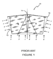
- Figure 1 illustrates schematically a package 10 of the prior art.
- an end view of the package 10 which comprises a group of articles A is shown.
- the articles A comprise a flange 16 about their upper periphery.
- the articles A are coupled to one another along a frangible connection 14, disposed between the articles.
- a sheet of material 12, such as shrink wrap plastic, or other polymeric material has been wrapped about the group of articles to form a tubular arrangement having an axis perpendicular to the plane of the paper.
- the effect of this compressive force F is that the articles A are caused to pivot about the frangible connection 14 such that the tops, of adjacent articles are disposed at an angular relationship to one another.
- Blank 120 comprises a base panel 122 in which a keel structure 140 is formed.
- Keel structure 140 comprises a first upright panel 128 defined in part by a substantially U shaped cut line 134 and in part by fold line 125.
- a second upright panel 124 disposed adjacent the first upright panel 128, is defined in part by a portion of fold line 125 and in part by a second fold line 123.
- Second upright panel 124 is further defined in part by portion of cut lines 130 and 132. Cut lines 130 and 132 are spaced apart and arranged such that second upright panel 124 is trapezoidal in shape.
- a connecting panel 126 is struck from first upright panel 128.
- Connecting panel 126 is formed in part by said aforementioned portion of fold line 125 (and thereby adjoined to second upright panel 124); by third fold line 127 and by further portions of cut lines 130 and 132.
- Connecting panel 126 is also substantially trapezoidal in shape.
- keel structure 140 is schematically illustrated after is has been folded out of the plane of base panel 122, such that a tubular structure is formed in a gap 117 between lower portions of adjacent articles A. Gap 117 is created by the presence of flange portions 116.
- the present invention may be used with articles having tapered sides such as frustoconical articles, it is envisaged that articles having other suitable, shapes can be held by the packages herein described.
- packages 110 preferably are constructed by first erecting the keel structure 140 in the gap 117 between adjacent articles A and then by applying the shrink wrap type material. However is envisaged that the construction process may differ from that herein described.
- the shrink wrap material 112 again applies a compressive force F to the articles A.
- the keel structure 140 however provides support to the base of the articles A to resist against the compressive force F. In this way the package 110 maintains its shape, leaving the tops and bases of each article A in substantially the same plane as the base of the shrink wrap type material 112.
- the keel structure 140 provides a spacer structure which prevents the pivoting seen in the prior art and maintains a minimum distance between adjacent articles, because the articles A are restricted from pivoting about the frangible connection 114.
- the articles A of the package 110 of the present invention are less likely to separate from one another due to undesirable breaking of the frangible connection 114 when the shrink wrap material 112 is applied, and/or during transportation.
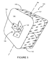
- Figure 5 shows the base of a package 110 in which it can be clearly seen that the keel structure 140 has been assembled in the gap 117 between adjacent articles A. Portions of the bases of two of the articles in the two by two array of articles A are visible through the aperture 150 formed in the base as a consequence of assembling the keel structure.
- the keel structure 140 forms a tubular structure having an axis (not shown) which is parallel to the axis A x formed by the tubular structure created by the shrink wrap material 112.
- the shrink wrap material 112 applies a compressive force F in directions substantially perpendicular to axis A x and the keel structure 140 provides structural rigidity to the package.
- FIG. 6 there is shown a perspective view from above of the package 110. It can be seen that the keel structure 140 maintains the bases of the articles in a spaced apart relationship.
- Figure 7 illustrates two keel structures 240 that have been formed in base panel 222 of blank 220.
- Blank 220 can be used to package a two by four array of eight articles A as shown in Figure 8.
- Figure 8 illustrates a perspective view of the base of a package 210 in which each keel structure 240 provides support to four surrounding articles A of the article group.
- Figure 9 illustrates the package 210 from above showing that the bases of the articles A are maintained in a spaced apart relationship by each of the keel structures 240.
- Figure 10 illustrates an alternative package 211 using the blank 220 in which a dual-layer-stack of articles are placed upon the base panel 222.
- a first layer of articles A1 are placed on base panel 222 with keel structure 240 placed in gap 217.
- a second layer of articles A2 are placed on the top of the first layer of articles A 1 .
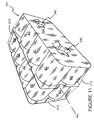
- Shrink wrap 212 is applied around both layers of articles A1 and A2 as shown in Figure 11 .
- the flanges 216 of the first layer of articles A1 prevent compressive forces of the shrink wrap type material 212 from displacing the articles in the upper layer A2.
- An insert is placed between the first A1 and second A2 layers.
- the keel structures 240 maintain the spaced apart relationship of the bases of the first layer of articles A1 as can be seen by reference to Figure 12 .
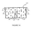
- a blank 320 comprising a base panel 322 side panels 334 and 336 hinged along fold lines 333 and 336 respectively to opposed edges of base panel 322.
- Keel structure 340 is formed in base panel 322 substantially the same as hereinbefore described.
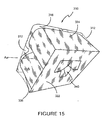
- Shrink wrap type material 312 is applied to the assembled article group and paperboard insert 310, as can be seen in Figure 15 .
- Side panels 334 and 336 offer protection to the sides of the article group and/or additional structural rigidity. Furthermore, they may be printed for advertising or display purposes.
- Figure 16 shows a package 311 according to the present invention comprising the blank 320 of Figure 13 in which a dual layer package has been created by placing a second layer of articles A2 over that of the first layer of articles A 1 .
- the flanges 316 of the first layer of articles A1 prevent the shrink wrap material 312 (not shown) from displacing the upper layer of articles A2.
- Blank 420 for forming a package of a second embodiment.
- Blank 420 comprises a base panel 422 to opposed sides of which are hinged lower side panels 434b and 436b along fold lines 433 and 435 respectively.
- Upper side panels 434a and 436a are hinged to lower side panels 434b and 436b along fold lines 437 and 439 respectively.
- a pair of keel structures 440 are struck from the base panel 422.
- FIGs 18 and 19 it can be seen that two layers of articles, A1, A2 have been placed on base panel 422, keel structures 440 have been inserted into the gap 417 between articles A1 of the lower layer of articles.
- Lower side panels 434b and 436b have been folded about the sides of the lower layer of articles A1 whilst the upper side panels 434a and 436a have been folded about the sides of the upper layer of articles A2.
- the upper and lower side panels 443a, 436a, 434b, 436b provide protection to both layers of articles A1 and A2 and provide the package 410 with display means for advertising and promotional purposes.
- the fold lines 437 and 439 are dimensioned and arranged to coincide with the upper periphery of the first layer of articles A1 such that the upper and lower side panels 434b, 436b, 434a, 436a fold about fold lines 437 and 439 at a position where the flanges 416 meet fold lines 437, 439.
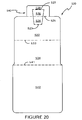
- FIG 20 there is shown a blank 520 for forming a package 510 illustrated schematically in Figure 21 .
- Blank 520 comprises a base panel 522, base panel 522 is provided to underlay half of the articles A in the article group, as can be seen in Figure 21 .
- a side panel 534 is coupled to base panel 522 by fold line 533.
- a top panel 542 is coupled to side panel 534 along fold line 541. Top panel 542 substantially covers all of the top of the article group.
- Keel structure 540 is struck in part from base panel 522, such that second upright panel 524 is struck in its entirety from base panel 522.
- First upright panel 528 is hinged to base panel 522 along fold line 525.
- Connection panel 526 is struck form first upright panel 528 and is coupled to second upright panel 524 by fold line 525.
- keel structure 540 is erected between the articles A in gap 517.
- Side panel 534 is folded about the side of the article group.
- Top panel 542 is folded to cover the top the article group.
- Side and top panels 534, 542 offer protection to the article group and provide a surface for printing graphics or other display information.
- Shrink wrap type material 512 is then applied to form a tubular structure which has an axis which is substantially parallel to the axis formed by the structure of the keel structure 540. In this way the keel structure 540 resists inward displacement of the articles A which would otherwise result as a consequence of the compression applied by the shrink wrap material.
- Figure 20b illustrates a package having a tear feature 570 in top panel 542.
- Top panel 542 comprises a tear feature 570 which separates the top panel 542 into two parts 542a and 542b.
- Tear feature 570 comprises a tear strip 572 defined in part by tear lines 574a and 574b. Tear lines 574a and 574b comprises a series of skewed U shaped cut lines 573.
- tear strip 572 is defined by a trapezoidal portion 576, defined by a pair of tear initiation lines 578a and 578b.
- Tear feature 570 may be deployed by pulling trapezoidal portion 576 and tearing the tear strip 572 away from the top panel 542. In doing so a user may easily gain access to the contents of the package, once upper portions of the shrink wrap material (not shown) have been removed. It is envisaged that other tear features could be incorporated into top panel 542 and/or any of the other panels to facilitate accessing of the articles A.
- the blank 620 comprises a base panel 622 having a pair of keel structures each of which is substantially the same as the keel structure 540 described in respect of the fifth embodiment above and therefore not further described.
- the base panel 622 is coupled to a lower side panel 634b along a fold line 633 to which is coupled an upper side panel 634a along a fold line 637.
- a top panel 642 is coupled to upper side panel 634a along fold line 641.
- Top panel 622 comprises a pair of finger engagement tabs 660 formed by curved cut lines 662a and 662b disposed at opposite ends of cut line 664, such that a portion between curved cut lines 662a, 662b and lines 664 defines, in part, a pair of tabs 666a, 666b wherein the tabs 666a, 666b are adapted to be folded about notional lines disposed between the extremities of curved lines 662a, 662b.
- Blank 620 can be assembled along with a group of articles A to form the package 670 shown schematically in Figure 23 .
- Keel structure 640 is erected in the gap 617 between adjacent Articles A1 of the lower layer.
- Lower side panel 634b is folded about the sides of the lower layer of articles A1 whilst the upper side panel 634a is folded about the sides of the upper layer of articles A2.
- Fold line 637 is dimensioned and arranged to coincide with flange 616 of the lower layer of articles A1.
- the top panel 642 is then folded to cover the top of the upper layer of articles A2.
- Shrink wrap type material 612 (not shown) is then applied to complete the package 610.
- the shrink wrap forms a tubular structure having an axis parallel to the axis of the tubular structure formed by the keel structure 640.
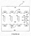
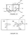
- Figure 24 illustrates a blank in which an alternative keel structure 740 is shown.
- Base panel 722 is coupled to side panels 734 and 736 along fold lines 733 and 735 respectively.
- Apertures 799 are optionally formed in part in base panel 722 and in part in side panels 734, 736. Apertures 799 receive portions of articles around which blank 710 is assembled.
- Keel structure 740 is formed form first upright panel 728 and second upright panel 724 coupled by connecting panel 726.
- connecting panel 726 is orientated to be perpendicular to the base panel 722.
- first and second upright panels 728, 724 are folded to be approximately perpendicular to connection panel 728, such that they extend across the aperture 750 formed from displacing panels 728, 726 and 724 out of the plane of base panel 722.
- Figures 27 and 28 show a keel structure 840.
- Figure 27 illustrates a plan view of a partial blank 820 for forming a package 810.
- Keel structure 840 comprises first upright panel 828 coupled to connecting panel 826 by curved nick portions 881 disposed at either end of curved cut line 827.
- Nick portions 881 are disposed between curved cut line 827 and cut lines 830.
- a first upright cut line 880 is disposed substantially perpendicularly relative to a portion of the curved cut line 827 such that the curved line 827 and upright cut line 880 intersect.
- Connecting panel 826 is coupled to second upright panel 824 by a similar arrangement of cut lines 825a, nick portions 883 and second upright cut line 882 which is a mirror image of that connecting first upright panel 828 to connection panel 826.
- Second upright panel 824 is hinged to a main carton panel 822 along fold line or score line 823 spaced from cut lines 830.
- the curved cut lines 827, 825a and upright cut lines 880, 882 provided a keel structure which is shaped and structured such that it can be deformed to bend partially around a curved article (not shown).
- the keel structure 840 In a package using the keel structure 840 it is envisaged that the keel structure 840 would be placed between a pair of articles rather than between four articles. In this way the upright panels can be deformed to accommodate an article disposed adjacent to them. Alternatively the keel structure is shaped to fit between other numbers and shapes of articles.
- FIG 29 shows a blank 920 for forming a keel structure 940 according to a third embodiment.
- Keel structure 940 comprises a first aperture 997 struck in part from first upright panel 928 and in part from connecting panel 926.
- a second aperture 998 is struck in part from connecting panel 926 and in part from second upright panel 924.
- Apertures 997 and 998 are substantially elliptical in shape.
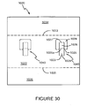
- Figure 30 shows a blank 1020 for forming a keel structure 1040 according to a fourth embodiment of the present invention.
- the fold line 1025a adjoining connecting panel 1026 to second upright panel 1024 is offset from the fold line 1025 connecting the first upright panel 1028 to the base panel 1022.
- This arrangement allows a keel structure to be formed in which the second upright panel 1024 is taller than the connecting panel 1026 is wide.
- the distance between fold line 1027 and fold line 1025 is substantially equal to the distance between fold line 1025a and fold line 1023.
- the keel structure 1040 In arranging the keel structure 1040 in this way the keel structure 1040 can be formed in between small gaps between articles, whilst maintaining the depth of penetration of the keel structure 1040 into the article group.
- Figure 31 shows a blank 1120 for forming a package having a keel structure.
- Base panel 1122 is coupled to side panel 1134 along fold line 1133.
- Side panel 1134 is hinged along fold line 1141 to top panel 1142.
- Base panel 1122 comprises a keel structure 1140.
- the keel structure comprises first upright panel 1124 and second and third upright panels 1124a, 1124b which couple spacer panel 1126 to base panel 1122 via hinge lines 1123 and 1125.
- Keel structure 1140 further comprises minor coupling panels 1144 which also couple spacer panel 1126 to base panel 1122 via hinge lines 1123a and 1125a disposed either side thereof.
- Spacer panel 1126 comprises recessed positions 1146 along a free edge for mating with articles in an article group.
- Curved cut lines 1148 provide a curved edge 1147 (see Figure 33 ) between spacer panel 1126 and side panel 1134 when the keel structure 1140 is assembled. Curved edge 1147 is provided to mate with articles placed between side panel 1134 and spacer panel 1126.
- the keel structure 1140 is intended to be placed between two rows of articles to prevent the articles from being compressed towards one another at their respective bases.
- Tabs 1190 are formed which, in the assembled package, partially underlay the articles A which mate with recessed portions 1146.
- Figure 32 illustrates the shape and configuration of the location of minor coupling panels 1244 has been moved towards the fold line 1233 between the base panel 1222 and side panel 1234.
- larger tabs 1290 are formed which can underlay articles mating with recessed portions 1246.
- Figure 34 illustrates a side view of a package 1420 formed from the blank 1410 of Figure 35 which forms a keel structure 1440.
- Keel structure 1440 in this embodiment forms a tubular structure with the remainder of the blank 1410 which requires its axis to be orientated at 90° to the axis of the tubular structure formed by the shrink wrap type material (not shown).
- the axis of the tubular structure of the shrink wrap type material is parallel to the plane of the paper.
- Keel structure 1440 comprises a first upright panel 1424 hinged to base panel 1422.
- a spacer panel 1426 is hinged along fold line 1425 to upright panel 1424 and also to side panel 1434 or, 1436 respectively.
- both the upright panel 1424 and the spacer panel 1426 act against the articles A, to prevent them being brought into closer proximity to one another.
- Shrink wrap type material is wrapped around the article group and insert such that it forms a tubular structure the tubular structure has a tubular axis by A x (not shown).
- the compressive force exerted by the shrink wrap type material is directed into the plane of the paper. It is not required to use a spacer means between the gap 1417 between the articles A to resist this force. However, a compressive force acting in the direction into the paper, acts on further articles A (not shown) disposed on an opposing side of the keel structure 1440 and this compressive force is resisted by the keel structure 1440, such that the two by two array of articles (only two can be seen in the view as illustrated) are supported by the keel structure.
- any directional references used in the above description are incorporated for clarity only and are not intended to be limiting. It will therefore be recognised that as used herein, that terms such as “top”, “base”, “side”, “end”, “inner”, “outer”, “upper” and “lower” with respect to the panels of the carton or carton blank are relative terms and that the carton formed from the blank may be reoriented as necessary or as desired.
- Any reference to a hinged or foldable connection should not be construed as necessarily referring to a single fold line only: indeed, it is envisaged that a hinged or foldable connection can be formed from one or more of the following, a score line, a frangible line or a fold line, without departing from the scope of the present invention.
- material other than paperboard may be used for the foldable insert for example, cardboard.
- the features described herein can be used in various combinations not all explicitly disclose herein but nevertheless envisaged as falling within the scope of the present invention.
- the number of keel structures provided is in other embodiments determined by the number of articles; the provision of one or more side panels and/or pairs of upper and lower side panels and/or top panel is entirely optional and can be combined in a variety of combinations with the various types of keel structure shown in forming a composite package.
- combinations of different types of keel structure may be incorporated into a single paperboard (or other suitable foldable sheet material) blank.
- apertures 799 will be used in conjunction with other types of keel structure and may be incorporated into others of the blanks shown.
Landscapes
- Engineering & Computer Science (AREA)
- Mechanical Engineering (AREA)
- Packages (AREA)
- Buffer Packaging (AREA)
Claims (6)
- Verbundwerkstoffverpackung (311; 410; 610), die zwei Lagen (A1, A2) von Gegenständen in einer gestapelten Anordnung umfasst, wobei jede Lage von Gegenständen wenigstens zwei benachbart angeordnete Gegenstände umfasst, die jeweils einen oberen Flanschabschnitt (316; 416; 616) aufweisen, der über die Ausdehnung eines Bodens eines jeden Gegenstands hervorsteht und einen Punkt einer zerbrechlichen Verbindung zwischen den wenigstens zwei angrenzend angeordneten Gegenständen bereitstellt; die Verbundwerkstoffverpackung weiterhin einen Bogen (312; 412; 612) aus polymeren Material umfasst, der die zwei Gegenstandsreihen umhüllt, derart, dass der Bogen eine Druckkraft auf die Gegenstände ausübt; und nur einen Einsatz (320; 420; 620), der eine Distanzstruktur (340) aufweist, die zwischen den Gegenständen angeordnet ist, um einen minimalen Abstand zwischen den Böden der Gegenstände aufrechtzuerhalten, wobei der Einsatz (320) eine Hauptwandfläche (322) und die Distanzstruktur (340; 440; 640) umfasst, die aus einer oder mehreren Wandflächen (324, 326, 328; 424, 426, 428; 624, 626, 628) ausgebildet ist, die wenigstens teilweise aus der Hauptwandfläche ausgestanzt und angelenkt sind an die Hauptwandfläche, die ein Paar erste (328; 428; 628) und zweite (324; 424; 624) senkrechte Wandflächen und eine Verbindungswandfläche (326; 426; 626) beinhaltet, und wobei jedes Paar der ersten und zweiten senkrechten Wandflächen einen entsprechenden der wenigstens zwei benachbart angeordneten Gegenstände in Eingriff nimmt, und wobei die Verbindungswandfläche eine Strebe zwischen den ersten und den zweiten senkrechten Wandflächen bereit stellt, wobei der Einsatz eine Bodenwandfläche (322; 422; 622) der Verbundwerkstoffverpackung ausbildet, und wobei die Distanzstruktur integral innerhalb der Bodenwandfläche ausgebildet ist und wobei der Einsatz weiterhin zwei Seitenwaridflächen (334, 336; 434a, 434b, 436a, 436b; 634a, 634b) umfasst, die an die Hauptwandflächen angelenkt sind, und wobei die Hauptwandflächen die in Kontakt mit einer Seite von wenigstens einer der Lagen des Stapels gefaltet sind, angelenkt sind und wobei kein weiterer Einsatz, der eine Distanzstruktur aufweist zwischen den zwei Lagen von Gegenständen angeordnet ist.
- Verbundwerkstoffverpackung gemäß Anspruch 1, wobei der Materialbogen (312; 412; 612) eine Hülle ausbildet, die eine Druckkraft auf die Gegenstände ausübt und wobei die Distanzstruktur derart strukturiert ist, dass sie der Druckkraft widersteht, die die Bewegung der Gegenstände zueinander begrenzt.
- Verbundwerkstoffverpackung gemäß einem der vorherigen Ansprüche, wobei das Bogenmaterial (312; 412; 612) eine röhrenförmige Struktur ausbildet, die eine Achse aufweist, die parallel zu einer Röhrenachse einer Röhre angeordnet ist, die durch die Distanzstruktur definiert ist.
- Verbundwerkstoffverpackung gemäß einem der Ansprüche 1 oder 2, wobei das Bogenmaterial (312; 412; 612) eine röhrenförmige Struktur ausbildet, die eine Achse aufweist, die senkrecht zu einer Röhrenachse einer Röhre angeordnet ist, die durch die Distanzstruktur definiert ist.
- Verbundwerkstoffverpackung gemäß einem der vorherigen Ansprüche, wobei das Bogenmaterial (312; 412; 612) ein polymeres Material ist und der Einsatz aus einem steiferen Material ausgebildet ist.
- Verbundwerkstoffverpackung nach einem der vorherigen Ansprüche, wobei das Bogenmaterial (312; 412; 612) um die Vielzahl von Gegenständen zusammenziehbar ist, und zwar durch Einwirken von Wärme auf das Bogenmaterial, wodurch eine Druckkraft erzeugt wird.
Applications Claiming Priority (1)
| Application Number | Priority Date | Filing Date | Title |
|---|---|---|---|
| GB0702966A GB0702966D0 (en) | 2007-02-15 | 2007-02-15 | Carton for multiple packaging and blank therefor |
Publications (3)
| Publication Number | Publication Date |
|---|---|
| EP2014573A2 EP2014573A2 (de) | 2009-01-14 |
| EP2014573A3 EP2014573A3 (de) | 2009-10-21 |
| EP2014573B1 true EP2014573B1 (de) | 2012-08-15 |
Family
ID=37908702
Family Applications (1)
| Application Number | Title | Priority Date | Filing Date |
|---|---|---|---|
| EP08101665A Not-in-force EP2014573B1 (de) | 2007-02-15 | 2008-02-15 | Mehrfachverpackung und Rohling dafür |
Country Status (3)
| Country | Link |
|---|---|
| EP (1) | EP2014573B1 (de) |
| GB (1) | GB0702966D0 (de) |
| RU (1) | RU2008105897A (de) |
Citations (1)
| Publication number | Priority date | Publication date | Assignee | Title |
|---|---|---|---|---|
| US3385429A (en) * | 1966-01-20 | 1968-05-28 | Reynolds Metals Co | Package construction and parts therefor or the like |
Family Cites Families (6)
| Publication number | Priority date | Publication date | Assignee | Title |
|---|---|---|---|---|
| US3302784A (en) | 1965-01-12 | 1967-02-07 | Meyer Geo J Mfg Co | Package assembly including a top member and an endless heat shrunk enclosure band |
| US3687282A (en) | 1970-05-05 | 1972-08-29 | Illinois Tool Works | Container package |
| US4094406A (en) | 1977-03-28 | 1978-06-13 | The Mead Corporation | Package for a group of articles |
| DE7724602U1 (de) * | 1977-08-08 | 1978-04-27 | Unilever Nv | Becherpackung |
| MA23035A1 (fr) * | 1992-11-20 | 1994-07-01 | Mead Corp | Structure de la quille dans les emballages enveloppants. |
| FR2735450A1 (fr) * | 1995-06-14 | 1996-12-20 | Monoplast Sa | Procede de groupage d'objets et plateau de mise en oeuvre |
-
2007
- 2007-02-15 GB GB0702966A patent/GB0702966D0/en not_active Ceased
-
2008
- 2008-02-15 RU RU2008105897/12A patent/RU2008105897A/ru not_active Application Discontinuation
- 2008-02-15 EP EP08101665A patent/EP2014573B1/de not_active Not-in-force
Patent Citations (1)
| Publication number | Priority date | Publication date | Assignee | Title |
|---|---|---|---|---|
| US3385429A (en) * | 1966-01-20 | 1968-05-28 | Reynolds Metals Co | Package construction and parts therefor or the like |
Also Published As
| Publication number | Publication date |
|---|---|
| RU2008105897A (ru) | 2009-08-20 |
| EP2014573A3 (de) | 2009-10-21 |
| EP2014573A2 (de) | 2009-01-14 |
| GB0702966D0 (en) | 2007-03-28 |
Similar Documents
| Publication | Publication Date | Title |
|---|---|---|
| JP7611133B2 (ja) | 容器用パッケージ | |
| EP1940698B1 (de) | Verpackung für behälter und zuschnitt | |
| US7762395B2 (en) | Carrier packages and methods of erecting carrier packages | |
| US7913844B2 (en) | Article carrier with retention features | |
| KR102568465B1 (ko) | 카톤, 이를 위한 블랭크 및 패키지 | |
| CN104470821B (zh) | 纸箱、纸箱坯料和物品保护插入件坯料的组合及形成纸箱的方法 | |
| EP1999033B1 (de) | Trägerpakete und verfahren zum aufrichten von trägerpaketen | |
| JP6041980B2 (ja) | インサート付きカートン | |
| US7299924B2 (en) | Edge protector | |
| US10173804B2 (en) | Carrier and blank therefor | |
| US11932472B2 (en) | Carton and blank therefor | |
| US20110253587A1 (en) | Carton tray | |
| JP2009525234A (ja) | 容器のためのパッケージ | |
| EP2125558A1 (de) | Verpackung für behälter | |
| MX2013013006A (es) | Portador con caracteristicas de retencion. | |
| EP2084079B1 (de) | Verpackung für behälter | |
| US20170225859A1 (en) | Carton and carton blank and a handle structure therefore | |
| WO2014052514A2 (en) | Package for articles, carton and blank therefor | |
| AU2017326156B2 (en) | Carton and carton blank | |
| WO2014014738A1 (en) | Carton and blank therefor | |
| AU2017350706B2 (en) | Basket style carrier, shipping carton and package system | |
| EP2014573B1 (de) | Mehrfachverpackung und Rohling dafür | |
| US20170158402A1 (en) | Carton and carton blank | |
| US20100102113A1 (en) | Packaging system | |
| WO2016164660A1 (en) | Carton and blank therefor |
Legal Events
| Date | Code | Title | Description |
|---|---|---|---|
| PUAI | Public reference made under article 153(3) epc to a published international application that has entered the european phase |
Free format text: ORIGINAL CODE: 0009012 |
|
| AK | Designated contracting states |
Kind code of ref document: A2 Designated state(s): AT BE BG CH CY CZ DE DK EE ES FI FR GB GR HR HU IE IS IT LI LT LU LV MC MT NL NO PL PT RO SE SI SK TR |
|
| AX | Request for extension of the european patent |
Extension state: AL BA MK RS |
|
| PUAL | Search report despatched |
Free format text: ORIGINAL CODE: 0009013 |
|
| AK | Designated contracting states |
Kind code of ref document: A3 Designated state(s): AT BE BG CH CY CZ DE DK EE ES FI FR GB GR HR HU IE IS IT LI LT LU LV MC MT NL NO PL PT RO SE SI SK TR |
|
| AX | Request for extension of the european patent |
Extension state: AL BA MK RS |
|
| 17P | Request for examination filed |
Effective date: 20091016 |
|
| 17Q | First examination report despatched |
Effective date: 20091124 |
|
| RAP1 | Party data changed (applicant data changed or rights of an application transferred) |
Owner name: MEADWESTVACO PACKAGING SYSTEMS LLC |
|
| AKX | Designation fees paid |
Designated state(s): AT BE BG CH CY CZ DE DK EE ES FI FR GB GR HR HU IE IS IT LI LT LU LV MC MT NL NO PL PT RO SE SI SK TR |
|
| RAP1 | Party data changed (applicant data changed or rights of an application transferred) |
Owner name: MEADWESTVACO PACKAGING SYSTEMS, LLC |
|
| GRAP | Despatch of communication of intention to grant a patent |
Free format text: ORIGINAL CODE: EPIDOSNIGR1 |
|
| GRAS | Grant fee paid |
Free format text: ORIGINAL CODE: EPIDOSNIGR3 |
|
| GRAA | (expected) grant |
Free format text: ORIGINAL CODE: 0009210 |
|
| AK | Designated contracting states |
Kind code of ref document: B1 Designated state(s): AT BE BG CH CY CZ DE DK EE ES FI FR GB GR HR HU IE IS IT LI LT LU LV MC MT NL NO PL PT RO SE SI SK TR |
|
| REG | Reference to a national code |
Ref country code: GB Ref legal event code: FG4D Ref country code: CH Ref legal event code: EP Ref country code: AT Ref legal event code: REF Ref document number: 570680 Country of ref document: AT Kind code of ref document: T Effective date: 20120815 |
|
| RIN1 | Information on inventor provided before grant (corrected) |
Inventor name: LE BRAS, PHILLIPPE Inventor name: DANIEL, JEAN-YVES |
|
| REG | Reference to a national code |
Ref country code: IE Ref legal event code: FG4D |
|
| REG | Reference to a national code |
Ref country code: DE Ref legal event code: R096 Ref document number: 602008017957 Country of ref document: DE Effective date: 20121018 |
|
| REG | Reference to a national code |
Ref country code: NL Ref legal event code: VDEP Effective date: 20120815 |
|
| REG | Reference to a national code |
Ref country code: AT Ref legal event code: MK05 Ref document number: 570680 Country of ref document: AT Kind code of ref document: T Effective date: 20120815 |
|
| PG25 | Lapsed in a contracting state [announced via postgrant information from national office to epo] |
Ref country code: FI Free format text: LAPSE BECAUSE OF FAILURE TO SUBMIT A TRANSLATION OF THE DESCRIPTION OR TO PAY THE FEE WITHIN THE PRESCRIBED TIME-LIMIT Effective date: 20120815 Ref country code: CY Free format text: LAPSE BECAUSE OF FAILURE TO SUBMIT A TRANSLATION OF THE DESCRIPTION OR TO PAY THE FEE WITHIN THE PRESCRIBED TIME-LIMIT Effective date: 20120815 Ref country code: HR Free format text: LAPSE BECAUSE OF FAILURE TO SUBMIT A TRANSLATION OF THE DESCRIPTION OR TO PAY THE FEE WITHIN THE PRESCRIBED TIME-LIMIT Effective date: 20120815 Ref country code: LT Free format text: LAPSE BECAUSE OF FAILURE TO SUBMIT A TRANSLATION OF THE DESCRIPTION OR TO PAY THE FEE WITHIN THE PRESCRIBED TIME-LIMIT Effective date: 20120815 Ref country code: AT Free format text: LAPSE BECAUSE OF FAILURE TO SUBMIT A TRANSLATION OF THE DESCRIPTION OR TO PAY THE FEE WITHIN THE PRESCRIBED TIME-LIMIT Effective date: 20120815 Ref country code: IS Free format text: LAPSE BECAUSE OF FAILURE TO SUBMIT A TRANSLATION OF THE DESCRIPTION OR TO PAY THE FEE WITHIN THE PRESCRIBED TIME-LIMIT Effective date: 20121215 Ref country code: NO Free format text: LAPSE BECAUSE OF FAILURE TO SUBMIT A TRANSLATION OF THE DESCRIPTION OR TO PAY THE FEE WITHIN THE PRESCRIBED TIME-LIMIT Effective date: 20121115 |
|
| PG25 | Lapsed in a contracting state [announced via postgrant information from national office to epo] |
Ref country code: GR Free format text: LAPSE BECAUSE OF FAILURE TO SUBMIT A TRANSLATION OF THE DESCRIPTION OR TO PAY THE FEE WITHIN THE PRESCRIBED TIME-LIMIT Effective date: 20121116 Ref country code: SE Free format text: LAPSE BECAUSE OF FAILURE TO SUBMIT A TRANSLATION OF THE DESCRIPTION OR TO PAY THE FEE WITHIN THE PRESCRIBED TIME-LIMIT Effective date: 20120815 Ref country code: SI Free format text: LAPSE BECAUSE OF FAILURE TO SUBMIT A TRANSLATION OF THE DESCRIPTION OR TO PAY THE FEE WITHIN THE PRESCRIBED TIME-LIMIT Effective date: 20120815 Ref country code: LV Free format text: LAPSE BECAUSE OF FAILURE TO SUBMIT A TRANSLATION OF THE DESCRIPTION OR TO PAY THE FEE WITHIN THE PRESCRIBED TIME-LIMIT Effective date: 20120815 Ref country code: PT Free format text: LAPSE BECAUSE OF FAILURE TO SUBMIT A TRANSLATION OF THE DESCRIPTION OR TO PAY THE FEE WITHIN THE PRESCRIBED TIME-LIMIT Effective date: 20121217 Ref country code: BE Free format text: LAPSE BECAUSE OF FAILURE TO SUBMIT A TRANSLATION OF THE DESCRIPTION OR TO PAY THE FEE WITHIN THE PRESCRIBED TIME-LIMIT Effective date: 20120815 Ref country code: PL Free format text: LAPSE BECAUSE OF FAILURE TO SUBMIT A TRANSLATION OF THE DESCRIPTION OR TO PAY THE FEE WITHIN THE PRESCRIBED TIME-LIMIT Effective date: 20120815 |
|
| PG25 | Lapsed in a contracting state [announced via postgrant information from national office to epo] |
Ref country code: NL Free format text: LAPSE BECAUSE OF FAILURE TO SUBMIT A TRANSLATION OF THE DESCRIPTION OR TO PAY THE FEE WITHIN THE PRESCRIBED TIME-LIMIT Effective date: 20120815 |
|
| PG25 | Lapsed in a contracting state [announced via postgrant information from national office to epo] |
Ref country code: ES Free format text: LAPSE BECAUSE OF FAILURE TO SUBMIT A TRANSLATION OF THE DESCRIPTION OR TO PAY THE FEE WITHIN THE PRESCRIBED TIME-LIMIT Effective date: 20121126 Ref country code: CZ Free format text: LAPSE BECAUSE OF FAILURE TO SUBMIT A TRANSLATION OF THE DESCRIPTION OR TO PAY THE FEE WITHIN THE PRESCRIBED TIME-LIMIT Effective date: 20120815 Ref country code: EE Free format text: LAPSE BECAUSE OF FAILURE TO SUBMIT A TRANSLATION OF THE DESCRIPTION OR TO PAY THE FEE WITHIN THE PRESCRIBED TIME-LIMIT Effective date: 20120815 Ref country code: DK Free format text: LAPSE BECAUSE OF FAILURE TO SUBMIT A TRANSLATION OF THE DESCRIPTION OR TO PAY THE FEE WITHIN THE PRESCRIBED TIME-LIMIT Effective date: 20120815 Ref country code: RO Free format text: LAPSE BECAUSE OF FAILURE TO SUBMIT A TRANSLATION OF THE DESCRIPTION OR TO PAY THE FEE WITHIN THE PRESCRIBED TIME-LIMIT Effective date: 20120815 |
|
| PG25 | Lapsed in a contracting state [announced via postgrant information from national office to epo] |
Ref country code: SK Free format text: LAPSE BECAUSE OF FAILURE TO SUBMIT A TRANSLATION OF THE DESCRIPTION OR TO PAY THE FEE WITHIN THE PRESCRIBED TIME-LIMIT Effective date: 20120815 Ref country code: IT Free format text: LAPSE BECAUSE OF FAILURE TO SUBMIT A TRANSLATION OF THE DESCRIPTION OR TO PAY THE FEE WITHIN THE PRESCRIBED TIME-LIMIT Effective date: 20120815 |
|
| PLBE | No opposition filed within time limit |
Free format text: ORIGINAL CODE: 0009261 |
|
| STAA | Information on the status of an ep patent application or granted ep patent |
Free format text: STATUS: NO OPPOSITION FILED WITHIN TIME LIMIT |
|
| 26N | No opposition filed |
Effective date: 20130516 |
|
| PG25 | Lapsed in a contracting state [announced via postgrant information from national office to epo] |
Ref country code: BG Free format text: LAPSE BECAUSE OF FAILURE TO SUBMIT A TRANSLATION OF THE DESCRIPTION OR TO PAY THE FEE WITHIN THE PRESCRIBED TIME-LIMIT Effective date: 20121115 |
|
| REG | Reference to a national code |
Ref country code: DE Ref legal event code: R097 Ref document number: 602008017957 Country of ref document: DE Effective date: 20130516 |
|
| PG25 | Lapsed in a contracting state [announced via postgrant information from national office to epo] |
Ref country code: MC Free format text: LAPSE BECAUSE OF NON-PAYMENT OF DUE FEES Effective date: 20130228 |
|
| REG | Reference to a national code |
Ref country code: CH Ref legal event code: PL |
|
| GBPC | Gb: european patent ceased through non-payment of renewal fee |
Effective date: 20130215 |
|
| PG25 | Lapsed in a contracting state [announced via postgrant information from national office to epo] |
Ref country code: CH Free format text: LAPSE BECAUSE OF NON-PAYMENT OF DUE FEES Effective date: 20130228 Ref country code: LI Free format text: LAPSE BECAUSE OF NON-PAYMENT OF DUE FEES Effective date: 20130228 |
|
| REG | Reference to a national code |
Ref country code: FR Ref legal event code: ST Effective date: 20131031 |
|
| REG | Reference to a national code |
Ref country code: IE Ref legal event code: MM4A |
|
| REG | Reference to a national code |
Ref country code: DE Ref legal event code: R119 Ref document number: 602008017957 Country of ref document: DE Effective date: 20130903 |
|
| PG25 | Lapsed in a contracting state [announced via postgrant information from national office to epo] |
Ref country code: FR Free format text: LAPSE BECAUSE OF NON-PAYMENT OF DUE FEES Effective date: 20130228 Ref country code: GB Free format text: LAPSE BECAUSE OF NON-PAYMENT OF DUE FEES Effective date: 20130215 Ref country code: DE Free format text: LAPSE BECAUSE OF NON-PAYMENT OF DUE FEES Effective date: 20130903 Ref country code: IE Free format text: LAPSE BECAUSE OF NON-PAYMENT OF DUE FEES Effective date: 20130215 |
|
| PG25 | Lapsed in a contracting state [announced via postgrant information from national office to epo] |
Ref country code: MT Free format text: LAPSE BECAUSE OF FAILURE TO SUBMIT A TRANSLATION OF THE DESCRIPTION OR TO PAY THE FEE WITHIN THE PRESCRIBED TIME-LIMIT Effective date: 20120815 |
|
| PG25 | Lapsed in a contracting state [announced via postgrant information from national office to epo] |
Ref country code: TR Free format text: LAPSE BECAUSE OF FAILURE TO SUBMIT A TRANSLATION OF THE DESCRIPTION OR TO PAY THE FEE WITHIN THE PRESCRIBED TIME-LIMIT Effective date: 20120815 |
|
| PG25 | Lapsed in a contracting state [announced via postgrant information from national office to epo] |
Ref country code: LU Free format text: LAPSE BECAUSE OF NON-PAYMENT OF DUE FEES Effective date: 20130215 Ref country code: HU Free format text: LAPSE BECAUSE OF FAILURE TO SUBMIT A TRANSLATION OF THE DESCRIPTION OR TO PAY THE FEE WITHIN THE PRESCRIBED TIME-LIMIT; INVALID AB INITIO Effective date: 20080215 |