EP2014454A1 - Laminator - Google Patents
Laminator Download PDFInfo
- Publication number
- EP2014454A1 EP2014454A1 EP08158174A EP08158174A EP2014454A1 EP 2014454 A1 EP2014454 A1 EP 2014454A1 EP 08158174 A EP08158174 A EP 08158174A EP 08158174 A EP08158174 A EP 08158174A EP 2014454 A1 EP2014454 A1 EP 2014454A1
- Authority
- EP
- European Patent Office
- Prior art keywords
- upper chamber
- diaphragm
- clamps
- chamber
- laminator
- Prior art date
- Legal status (The legal status is an assumption and is not a legal conclusion. Google has not performed a legal analysis and makes no representation as to the accuracy of the status listed.)
- Granted
Links
- NJPPVKZQTLUDBO-UHFFFAOYSA-N novaluron Chemical compound C1=C(Cl)C(OC(F)(F)C(OC(F)(F)F)F)=CC=C1NC(=O)NC(=O)C1=C(F)C=CC=C1F NJPPVKZQTLUDBO-UHFFFAOYSA-N 0.000 claims abstract description 11
- 239000000945 filler Substances 0.000 description 10
- 238000010438 heat treatment Methods 0.000 description 5
- 238000003475 lamination Methods 0.000 description 5
- 238000010586 diagram Methods 0.000 description 4
- DQXBYHZEEUGOBF-UHFFFAOYSA-N but-3-enoic acid;ethene Chemical compound C=C.OC(=O)CC=C DQXBYHZEEUGOBF-UHFFFAOYSA-N 0.000 description 3
- 239000005038 ethylene vinyl acetate Substances 0.000 description 3
- 239000000155 melt Substances 0.000 description 3
- 230000002093 peripheral effect Effects 0.000 description 3
- 229920001200 poly(ethylene-vinyl acetate) Polymers 0.000 description 3
- 239000006059 cover glass Substances 0.000 description 2
- 238000004132 cross linking Methods 0.000 description 2
- 238000004519 manufacturing process Methods 0.000 description 2
- 239000002184 metal Substances 0.000 description 2
- 230000002265 prevention Effects 0.000 description 2
- 238000010276 construction Methods 0.000 description 1
- 230000007423 decrease Effects 0.000 description 1
- 230000000694 effects Effects 0.000 description 1
- 239000011521 glass Substances 0.000 description 1
- 239000000463 material Substances 0.000 description 1
- 238000000034 method Methods 0.000 description 1
- 229920013716 polyethylene resin Polymers 0.000 description 1
- 238000003825 pressing Methods 0.000 description 1
- 230000001681 protective effect Effects 0.000 description 1
- 238000009877 rendering Methods 0.000 description 1
- 229920005989 resin Polymers 0.000 description 1
- 239000011347 resin Substances 0.000 description 1
Images


Classifications
-
- B—PERFORMING OPERATIONS; TRANSPORTING
- B32—LAYERED PRODUCTS
- B32B—LAYERED PRODUCTS, i.e. PRODUCTS BUILT-UP OF STRATA OF FLAT OR NON-FLAT, e.g. CELLULAR OR HONEYCOMB, FORM
- B32B37/00—Methods or apparatus for laminating, e.g. by curing or by ultrasonic bonding
- B32B37/0046—Methods or apparatus for laminating, e.g. by curing or by ultrasonic bonding characterised by constructional aspects of the apparatus
-
- H—ELECTRICITY
- H01—ELECTRIC ELEMENTS
- H01L—SEMICONDUCTOR DEVICES NOT COVERED BY CLASS H10
- H01L31/00—Semiconductor devices sensitive to infrared radiation, light, electromagnetic radiation of shorter wavelength or corpuscular radiation and specially adapted either for the conversion of the energy of such radiation into electrical energy or for the control of electrical energy by such radiation; Processes or apparatus specially adapted for the manufacture or treatment thereof or of parts thereof; Details thereof
- H01L31/18—Processes or apparatus specially adapted for the manufacture or treatment of these devices or of parts thereof
-
- B—PERFORMING OPERATIONS; TRANSPORTING
- B30—PRESSES
- B30B—PRESSES IN GENERAL
- B30B5/00—Presses characterised by the use of pressing means other than those mentioned in the preceding groups
- B30B5/02—Presses characterised by the use of pressing means other than those mentioned in the preceding groups wherein the pressing means is in the form of a flexible element, e.g. diaphragm, urged by fluid pressure
-
- H—ELECTRICITY
- H01—ELECTRIC ELEMENTS
- H01L—SEMICONDUCTOR DEVICES NOT COVERED BY CLASS H10
- H01L31/00—Semiconductor devices sensitive to infrared radiation, light, electromagnetic radiation of shorter wavelength or corpuscular radiation and specially adapted either for the conversion of the energy of such radiation into electrical energy or for the control of electrical energy by such radiation; Processes or apparatus specially adapted for the manufacture or treatment thereof or of parts thereof; Details thereof
- H01L31/04—Semiconductor devices sensitive to infrared radiation, light, electromagnetic radiation of shorter wavelength or corpuscular radiation and specially adapted either for the conversion of the energy of such radiation into electrical energy or for the control of electrical energy by such radiation; Processes or apparatus specially adapted for the manufacture or treatment thereof or of parts thereof; Details thereof adapted as photovoltaic [PV] conversion devices
-
- B—PERFORMING OPERATIONS; TRANSPORTING
- B32—LAYERED PRODUCTS
- B32B—LAYERED PRODUCTS, i.e. PRODUCTS BUILT-UP OF STRATA OF FLAT OR NON-FLAT, e.g. CELLULAR OR HONEYCOMB, FORM
- B32B2457/00—Electrical equipment
- B32B2457/12—Photovoltaic modules
-
- Y—GENERAL TAGGING OF NEW TECHNOLOGICAL DEVELOPMENTS; GENERAL TAGGING OF CROSS-SECTIONAL TECHNOLOGIES SPANNING OVER SEVERAL SECTIONS OF THE IPC; TECHNICAL SUBJECTS COVERED BY FORMER USPC CROSS-REFERENCE ART COLLECTIONS [XRACs] AND DIGESTS
- Y02—TECHNOLOGIES OR APPLICATIONS FOR MITIGATION OR ADAPTATION AGAINST CLIMATE CHANGE
- Y02E—REDUCTION OF GREENHOUSE GAS [GHG] EMISSIONS, RELATED TO ENERGY GENERATION, TRANSMISSION OR DISTRIBUTION
- Y02E10/00—Energy generation through renewable energy sources
- Y02E10/50—Photovoltaic [PV] energy
-
- Y—GENERAL TAGGING OF NEW TECHNOLOGICAL DEVELOPMENTS; GENERAL TAGGING OF CROSS-SECTIONAL TECHNOLOGIES SPANNING OVER SEVERAL SECTIONS OF THE IPC; TECHNICAL SUBJECTS COVERED BY FORMER USPC CROSS-REFERENCE ART COLLECTIONS [XRACs] AND DIGESTS
- Y10—TECHNICAL SUBJECTS COVERED BY FORMER USPC
- Y10T—TECHNICAL SUBJECTS COVERED BY FORMER US CLASSIFICATION
- Y10T156/00—Adhesive bonding and miscellaneous chemical manufacture
- Y10T156/18—Surface bonding means and/or assembly means with handle or handgrip
Definitions
- the present invention relates to a laminator for manufacturing laminated objects such as photovoltaic modules, and more particularly, to a diaphragm mounting structure used in such a laminator.
- Examples of conventional laminators used to manufacture photovoltaic modules are described, for example, in Japanese Unexamined Patent Application Publication No. 9-141743 ( JP-H09-141743-A ), Japanese Unexamined Patent Application Publication No. 11-204811 ( JP-H11-204811-A ), and Japanese Registered Utility Model No. 3037201 ( JP-3037201-U ).
- an arrangement is employed in which upper and lower chambers are used.
- the upper chamber is movable vertically, or openably closable, with respect to the lower chamber, and has at its lower end a downwardly expandable diaphragm.
- the lower chamber has a support pedestal including a heating plate inside. When the upper chamber descends, or closes, it acts as a lid on the lower chamber.
- the laminator is used in the following way: First, with the upper chamber raised and opened, a workpiece placed on a conveyer belt is conveyed to and placed on the heating plate provided in the lower chamber.
- a photovoltaic module workpiece has a bottommost layer that is a glass plate, on top of which are layered, in order, a sheet-like filler, the photovoltaic cells, and then another sheet-like filler, with an uppermost layer consisting of a sheet-like backing.
- the upper chamber is then stacked on top of the lower chamber and the air in both the upper chamber and the lower chamber is removed to form a vacuum, in which the workpiece is heated.
- the usual method of fixing the diaphragm onto the upper chamber is to prepare a rectangular mounting frame shaped to fit the outer form of the upper chamber and sandwich and fix in place an outer peripheral portion of the diaphragm between the mounting frame and the upper chamber.
- Multiple bolt holes are opened in the periphery of the diaphragm, and multiple screw holes are provided at corresponding positions in the mounting frame.
- through-holes are provided in the upper chamber at positions corresponding to the bolt holes and the screw holes, such that, when the diaphragm is sandwiched between the upper chamber and the mounting frame, bolts are inserted in the through-holes, screwed into the screw holes in the mounting frame, and tightened, fixing the diaphragm in place.
- a laminator 10 shown in FIG. 6 includes a rectangular upper chamber 11 and a lower chamber 12 having a top face of the same shape as a bottom face of the upper chamber 11.
- the upper chamber 11 has a suction port 11a connected to a vacuum pump for depressurization, with a similar suction port 12a formed in the lower chamber 12.
- a support pedestal 13 on which is set a photovoltaic module workpiece A is disposed inside the lower chamber 12.
- a diaphragm 14 is of the same shape as or slightly larger than the upper chamber 11, with a peripheral portion thereof sandwiched between the upper chamber 11 and a mounting frame 15.
- the mounting frame 15 is a metal rectangular frame of the same shape and size as the upper chamber 11, on the outside of which are provided multiple hooks 15a.
- Clamps 16 are mounted on the upper chamber 11 at positions corresponding to the positions of the hooks 15a.
- Each of the clamps 16 includes a clamp lever 16a and a clamp ring 16b.
- the clamp lever 16a is rotatable about a shaft 16c.
- a groove is formed in the bottom face of the upper chamber 11 that contacts the mounting frame 15.
- a first 0-ring 17 is inserted into the groove to make contact between the upper chamber 11 and the diaphragm 14 airtight.
- a groove is formed in the bottom face of the mounting frame 15 and a second 0-ring 18 inserted into the groove, such that, when the upper chamber 11 is set on top of the lower chamber 12, the space between the upper and lower chambers 11 and 12 is airtight.
- the mounting frame is metal and substantially the same size as the bottom face of the upper chamber 11.
- the size of photovoltaic modules increases year by year.
- mounting frames are also getting larger and therefore also heavier, which means that they can be awkward to handle.
- the present invention provides a laminator of which the diaphragm can be mounted and removed easily without the use of a mounting frame.
- the present invention provides a laminator comprising an upper chamber, a diaphragm mounted on a bottom surface of the upper chamber, and a lower chamber, on which the upper chamber is stacked and which includes a support pedestal on which a workpiece A to be laminated is set.
- the diaphragm is larger than the upper chamber, such that an excess portion of the diaphragm protruding outside the upper chamber in a state in which the diaphragm is mounted on the upper chamber is folded upward and clamped against sides of the upper chamber by a plurality of clamps to fix the diaphragm in place on the upper chamber.
- Each of the clamps may have an operating lever that, when operated, enables one-touch switching between a clamped state and an unclamped state of the diaphragm against the sides of the upper chamber.
- the upper chamber may have a rectangular shape and the plurality of clamps is provided only along opposed long sides of the rectangular-shaped upper chamber.
- a flat panel may be inserted between the clamps and the diaphragm when the excess portion of the diaphragm that protrudes outside the upper chamber when the diaphragm is mounted on the upper chamber is folded upward and clamped against the sides of the upper chamber by the plurality of clamps.
- the diaphragm is fixed in place on the lateral side surfaces of the upper chamber, rendering use of a mounting frame unnecessary.
- the unique effect of such an arrangement is that the diaphragm can be mounted quickly and easily.
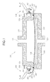
- FIG. 1 is a sectional view of essential portions of a laminator 100 according to the present invention, before a diaphragm is clamped in place.
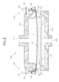
- FIG. 2 is a sectional view of the laminator of FIG. 1 , with the diaphragm clamped in place.
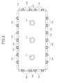
- FIG. 3 is a plan view of an upper chamber with the diaphragm mounted thereon.
- the laminator 100 includes an upper chamber 110 and a lower chamber 120.
- a bottom face 113 of the upper chamber 110 and a top face 122 of the lower chamber 120 are rectangles of the same size.
- Three suction ports 111 coupled to a vacuum pump, not shown, are provided at a top of the upper chamber 110.
- three other suction ports 121 are provided at a bottom of the lower chamber 120.
- a support pedestal 30 is provided in an interior space of the upper chamber 120.
- the diaphragm is mounted as follows: First, the upper chamber 110 is lifted upward and a diaphragm 140 is spread over the top of the lower chamber 120.
- the diaphragm 140 is larger than the lower chamber 120 both lengthwise and widthwise, and therefore a periphery thereof protrudes outside the lower chamber 120.
- the upper chamber 110 is lowered onto the lower chamber 120.
- the diaphragm 140 protrudes outside the portions where the upper chamber 110 and the lower chamber 120 meet. At this time, clamps 160 of the upper chamber 110 are in an open state.
- Each clamp 160 includes an operating lever 161 and a smaller pressure lever 162, with a pressure bolt 163 provided on the pressure lever 162. Adjusting a length of the pressure bolt 163 adjusts the pressing force.
- Reference numeral 164 designates an annular spring 164 that is described in greater detail later.
- the operating levers 161 of the clamps 160 are rotated in a direction indicated by arrows X in FIG. 1 and a link mechanism causes the pressure levers 162 to rotate with them in an opposite direction as indicated by separate arrows Y.
- a link mechanism causes the pressure levers 162 to rotate with them in an opposite direction as indicated by separate arrows Y.
- tips of the pressure bolts 163 press the diaphragm 140 against the lateral side surfaces 112 of the upper chamber 110, fixing the diaphragm in place.
- the annular springs 164 are stretched around them to keep the operating levers 161 vertical and thus prevent the operating levers 161 from inadvertently rotating, or being rotated, to an unlocked position.
- the clamps 160 are disposed along opposed long sides and short sides of the upper chamber 110. When all these clamps 160 are put into the state shown in FIG. 2 , the diaphragm 140 is fixed in place on the upper chamber 110.
- a mounting frame is not needed to mount the diaphragm 140 on the upper chamber 110.
- the clamps 160 can be switched between a clamped state and an unclamped state at a touch, which is very simple and easy. The foregoing configuration enables the diaphragm 140 to be mounted on and removed from the upper chamber 110 with ease.
- the diaphragm 140 is fixed in place along the lateral side surfaces 112 of the upper chamber 110, the diaphragm 140 is not in any way held against the bottom face of the upper chamber 110. Therefore, the diaphragm 140 in its natural state sags at the center as shown in FIG. 2 . Consequently, an O-ring 170 is provided in a groove in the bottom face 113 of the upper chamber 110. The O-ring 170 maintains an airtight contact between the upper chamber 110 and the diaphragm 140.
- the clamps 160 are provided along both the short and long sides of the upper chamber 110.
- the clamps along the short sides may be omitted. This is because, when the upper chamber 110 is set on the lower chamber 120 and the pressure inside the upper chamber 110 is reduced by the vacuum pump via the suction ports 111, if the diaphragm 140 is small or light it is sucked against the bottom face 113 of the upper chamber 110 at the short sides anyway, eliminating any gap. Even with a slight leak a predetermined reduced pressure can be easily maintained by operating the vacuum pump continuously.
- FIG. 4 is a diagram showing the upper chamber 110 and the lower chamber 120 stacked together, with a workpiece A on a support pedestal 130 being heated.
- a photovoltaic module workpiece A is composed of strings connecting a plurality of photovoltaic cells, filler, a transparent cover glass, and a backing. The strings are immersed in the filler and sandwiched between the transparent cover glass on the bottom and the backing on the top.
- An opaque material such as polyethylene resin, for example, may be used as the backing.
- EVA (ethylene vinyl acetate) resin, for example, may be used for the filler.
- a protective peel-off sheet 210 is interposed between the diaphragm 140 and the workpiece A to prevent the filler inside the workpiece A from sticking to the diaphragm 140 when the filler melts.
- the upper chamber 110 is lowered onto the lower chamber 120 and tightly contacted thereagainst.
- the 0-ring 170 keeps the contact between the lower chamber 120 and the conveyor belt 200 airtight. Air is then sucked out of the upper and lower spaces partitioned by the diaphragm 140 through the suction ports 111 and 121 and the pressure reduced.
- a heating plate built into the support pedestal 130 heats the workpiece A.
- air is reintroduced into the interior of the upper chamber 110, causing the diaphragm 140 to expand in conformity with the shape of the workpiece A as shown in FIG. 4 and press down on the workpiece A. In this state the workpiece A is heated, the filler melts, a cross-linking reaction occurs, the EVA filler becomes fully transparent, and a photovoltaic module is laminated.
- the upper chamber 110 is returned to a standby position above the lower chamber 120 as shown in FIG. 2 and the center of the diaphragm 140 sags downward somewhat in its natural state. Since the diaphragm 140 returns to its natural state, the deformation of the 0-ring 170 during lamination disappears and the 0-ring 170 returns to its initial state. Therefore, in the present invention, even with repeated lamination the deformation of the O-ring 170 does not accumulate but is experienced only once. As a result, the life of the O-ring 170 is extended.
- the diaphragm 140 is folded upward and held at the lateral side surfaces of the upper chamber 110 with great retentive force.
- the diaphragm is held by press-contact in a flat plane by a tensile force exerted when the diaphragm expands, with the result that sometimes the edges of the diaphragm 140 are pulled into the interior of the chamber, thus breaking the vacuum. In the present invention such a phenomenon no longer occurs.
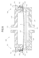
- FIG. 5 is a cross-sectional view of a second embodiment of the present invention.
- a flat panel 165 is inserted between the pressure bolts 163 of the clamps 160 and the diaphragm 140.
- the diaphragm 140 can be pressed by the flat panel 165 over an entire plane instead of at discrete points, facilitating prevention of leakage in the vacuum.
- the flat panel 165 may be of any length, a length that can straddle a plurality of the clamps 160 enables the diaphragm 140 to be pressed against one entire long side of the upper chamber 110, so as to provide even more reliable prevention of leakage in the vacuum.
- an angle bar may be used for the flat panel 165.
- the flat panel 165 is connected to the pressure bolts 163.
Abstract
Description
- The present specification claims priority from Japanese Patent Application No.
2007-155801, filed on June 13, 2007 - The present invention relates to a laminator for manufacturing laminated objects such as photovoltaic modules, and more particularly, to a diaphragm mounting structure used in such a laminator.
- Examples of conventional laminators used to manufacture photovoltaic modules are described, for example, in Japanese Unexamined Patent Application Publication No.
9-141743 JP-H09-141743-A 11-204811 JP-H11-204811-A 3037201 JP-3037201-U - The laminator is used in the following way: First, with the upper chamber raised and opened, a workpiece placed on a conveyer belt is conveyed to and placed on the heating plate provided in the lower chamber. A photovoltaic module workpiece has a bottommost layer that is a glass plate, on top of which are layered, in order, a sheet-like filler, the photovoltaic cells, and then another sheet-like filler, with an uppermost layer consisting of a sheet-like backing. The upper chamber is then stacked on top of the lower chamber and the air in both the upper chamber and the lower chamber is removed to form a vacuum, in which the workpiece is heated. Subsequently, air is introduced into only the upper chamber, causing the diaphragm to expand and sandwiching the photovoltaic module workpiece between the top face of the heating plate and the diaphragm. The heat from the heating plate melts the filler, causing a cross-linking reaction and curing to form the laminated object.
- The usual method of fixing the diaphragm onto the upper chamber is to prepare a rectangular mounting frame shaped to fit the outer form of the upper chamber and sandwich and fix in place an outer peripheral portion of the diaphragm between the mounting frame and the upper chamber. Multiple bolt holes are opened in the periphery of the diaphragm, and multiple screw holes are provided at corresponding positions in the mounting frame. Further, through-holes are provided in the upper chamber at positions corresponding to the bolt holes and the screw holes, such that, when the diaphragm is sandwiched between the upper chamber and the mounting frame, bolts are inserted in the through-holes, screwed into the screw holes in the mounting frame, and tightened, fixing the diaphragm in place.
- However, with such a mounting arrangement, when the diaphragm expands tensile stress is exerted on the portions of the periphery of the diaphragm that are compressed by the mounting frame. This tensile stress extends to the diaphragm bolt hole portions as well, the bolt holes tear, gradually grow large, and are damaged, and eventually become unable to maintain a vacuum. Moreover, if the diaphragm is damaged, it must, of course, be replaced. Removing a damaged diaphragm involves removing all the multiple bolts. These bolts must then be reinserted and re-tightened in order to mount the new diaphragm. Thus, replacing the diaphragm generates costs and adds to down-time of the laminator.
- One approach to solving the above-described problem is a laminator like that shown in
FIG. 6 and a diaphragm mounting structure, proposed by the applicant in Japanese Patent No.3890206 JP-3890206-B - A
laminator 10 shown inFIG. 6 includes a rectangularupper chamber 11 and alower chamber 12 having a top face of the same shape as a bottom face of theupper chamber 11. Theupper chamber 11 has a suction port 11a connected to a vacuum pump for depressurization, with asimilar suction port 12a formed in thelower chamber 12. Asupport pedestal 13 on which is set a photovoltaic module workpiece A is disposed inside thelower chamber 12. Adiaphragm 14 is of the same shape as or slightly larger than theupper chamber 11, with a peripheral portion thereof sandwiched between theupper chamber 11 and amounting frame 15. - The
mounting frame 15 is a metal rectangular frame of the same shape and size as theupper chamber 11, on the outside of which are providedmultiple hooks 15a.Clamps 16 are mounted on theupper chamber 11 at positions corresponding to the positions of thehooks 15a. Each of theclamps 16 includes aclamp lever 16a and aclamp ring 16b. Theclamp lever 16a is rotatable about ashaft 16c. When thehook 15a is inserted into theclamp ring 16b and theclamp lever 16a is rotated from a substantially horizontal position to the vertical position shown inFIG. 6 , thediaphragm 14 can be compressed and sandwiched between themounting frame 15 and theupper chamber 11. - A groove is formed in the bottom face of the
upper chamber 11 that contacts themounting frame 15. A first 0-ring 17 is inserted into the groove to make contact between theupper chamber 11 and thediaphragm 14 airtight. - Similarly, a groove is formed in the bottom face of the
mounting frame 15 and a second 0-ring 18 inserted into the groove, such that, when theupper chamber 11 is set on top of thelower chamber 12, the space between the upper andlower chambers - With such a structure, there is no need to open bolt holes in the
diaphragm 14, and thus the life of the diaphragm can be extended. In addition, using clamps instead of bolts in the fixing of themounting frame 15 simplifies the work of removing and replacing thediaphragm 14, enabling replacement time to be shortened. - However, in the arrangement disclosed in Japanese Patent No.
3890206 JP-3890206-B upper chamber 11. At the same time, the size of photovoltaic modules increases year by year. As a result, mounting frames are also getting larger and therefore also heavier, which means that they can be awkward to handle. - The present invention provides a laminator of which the diaphragm can be mounted and removed easily without the use of a mounting frame.
- The present invention provides a laminator comprising an upper chamber, a diaphragm mounted on a bottom surface of the upper chamber, and a lower chamber, on which the upper chamber is stacked and which includes a support pedestal on which a workpiece A to be laminated is set. The diaphragm is larger than the upper chamber, such that an excess portion of the diaphragm protruding outside the upper chamber in a state in which the diaphragm is mounted on the upper chamber is folded upward and clamped against sides of the upper chamber by a plurality of clamps to fix the diaphragm in place on the upper chamber.
- Each of the clamps may have an operating lever that, when operated, enables one-touch switching between a clamped state and an unclamped state of the diaphragm against the sides of the upper chamber.
- In addition, the upper chamber may have a rectangular shape and the plurality of clamps is provided only along opposed long sides of the rectangular-shaped upper chamber.
- Moreover, a flat panel may be inserted between the clamps and the diaphragm when the excess portion of the diaphragm that protrudes outside the upper chamber when the diaphragm is mounted on the upper chamber is folded upward and clamped against the sides of the upper chamber by the plurality of clamps.
- In the laminator having the construction described above, the diaphragm is fixed in place on the lateral side surfaces of the upper chamber, rendering use of a mounting frame unnecessary. The unique effect of such an arrangement is that the diaphragm can be mounted quickly and easily.
- Other features and advantages of the present invention will be apparent from the following description when taken in conjunction with the accompanying drawings, in which like reference characters designate similar or identical parts throughout the several views thereof.
-
-
FIG. 1 is a sectional view of essential portions of a laminator according to the present invention; -
FIG. 2 is a sectional view of the laminator ofFIG. 1 , with a diaphragm clamped in place; -
FIG. 3 is a plan view of the upper chamber with the diaphragm mounted thereon; -
FIG. 4 is a diagram showing the upper chamber and a lower chamber stacked together, with a workpiece on a support pedestal being heated; -
FIG. 5 is a diagram showing a second embodiment of the present invention, in which a flat panel is provided at tips of pressure bolts of clamps; and -
FIG. 6 is a diagram showing an example of a diaphragm mounting structure in a conventional laminator. - A detailed description will now be given of illustrative embodiments of the present invention, with reference to the accompanying drawings.
-
FIG. 1 is a sectional view of essential portions of alaminator 100 according to the present invention, before a diaphragm is clamped in place.FIG. 2 is a sectional view of the laminator ofFIG. 1 , with the diaphragm clamped in place.FIG. 3 is a plan view of an upper chamber with the diaphragm mounted thereon. - The
laminator 100 includes anupper chamber 110 and alower chamber 120. Abottom face 113 of theupper chamber 110 and atop face 122 of thelower chamber 120 are rectangles of the same size. Threesuction ports 111 coupled to a vacuum pump, not shown, are provided at a top of theupper chamber 110. Similarly, threeother suction ports 121, not shown in the plan view, are provided at a bottom of thelower chamber 120. A support pedestal 30 is provided in an interior space of theupper chamber 120. - The diaphragm is mounted as follows: First, the
upper chamber 110 is lifted upward and adiaphragm 140 is spread over the top of thelower chamber 120. Thediaphragm 140 is larger than thelower chamber 120 both lengthwise and widthwise, and therefore a periphery thereof protrudes outside thelower chamber 120. Once thediaphragm 140 is spread out, theupper chamber 110 is lowered onto thelower chamber 120. Thediaphragm 140 protrudes outside the portions where theupper chamber 110 and thelower chamber 120 meet. At this time, clamps 160 of theupper chamber 110 are in an open state. - Each
clamp 160 includes an operatinglever 161 and asmaller pressure lever 162, with apressure bolt 163 provided on thepressure lever 162. Adjusting a length of thepressure bolt 163 adjusts the pressing force.Reference numeral 164 designates anannular spring 164 that is described in greater detail later. - In the state shown in
FIG. 1 , that portion of thediaphragm 140 which protrudes from thelower chamber 120 is folded upward against lateral side surfaces 112 of theupper chamber 110. - Next, the operating
levers 161 of theclamps 160 are rotated in a direction indicated by arrows X inFIG. 1 and a link mechanism causes the pressure levers 162 to rotate with them in an opposite direction as indicated by separate arrows Y. When the operating levers 161 reach the vertical position shown inFIG. 2 , tips of thepressure bolts 163 press thediaphragm 140 against the lateral side surfaces 112 of theupper chamber 110, fixing the diaphragm in place. Once the operatinglevers 161 are vertical, theannular springs 164 are stretched around them to keep the operatinglevers 161 vertical and thus prevent the operating levers 161 from inadvertently rotating, or being rotated, to an unlocked position. - As shown in
FIG. 3 , theclamps 160 are disposed along opposed long sides and short sides of theupper chamber 110. When all theseclamps 160 are put into the state shown inFIG. 2 , thediaphragm 140 is fixed in place on theupper chamber 110. - In the laminator of the present invention, a mounting frame is not needed to mount the
diaphragm 140 on theupper chamber 110. In addition, by rotating the operating levers 161 theclamps 160 can be switched between a clamped state and an unclamped state at a touch, which is very simple and easy. The foregoing configuration enables thediaphragm 140 to be mounted on and removed from theupper chamber 110 with ease. - Although the
diaphragm 140 is fixed in place along the lateral side surfaces 112 of theupper chamber 110, thediaphragm 140 is not in any way held against the bottom face of theupper chamber 110. Therefore, thediaphragm 140 in its natural state sags at the center as shown inFIG. 2 . Consequently, an O-ring 170 is provided in a groove in thebottom face 113 of theupper chamber 110. The O-ring 170 maintains an airtight contact between theupper chamber 110 and thediaphragm 140. - In the embodiment described above, the
clamps 160 are provided along both the short and long sides of theupper chamber 110. Alternatively, however, where the diaphragm is small or light, the clamps along the short sides may be omitted. This is because, when theupper chamber 110 is set on thelower chamber 120 and the pressure inside theupper chamber 110 is reduced by the vacuum pump via thesuction ports 111, if thediaphragm 140 is small or light it is sucked against thebottom face 113 of theupper chamber 110 at the short sides anyway, eliminating any gap. Even with a slight leak a predetermined reduced pressure can be easily maintained by operating the vacuum pump continuously. - It should be noted that, depending on the capabilities of the particular vacuum pump, ordinarily the pump does not stop even when a desired state of reduced pressure is reached but continues to operate anyway. Once the desired pressure is achieved, between having a leak and having no leak a load on the vacuum pump does increase somewhat in the case of the former, but the increase is not great enough to pose a problem.
- A description is now given of the manner in which the laminator of the present invention laminates a photovoltaic module using
FIG. 4 . -
FIG. 4 is a diagram showing theupper chamber 110 and thelower chamber 120 stacked together, with a workpiece A on asupport pedestal 130 being heated. - A photovoltaic module workpiece A is composed of strings connecting a plurality of photovoltaic cells, filler, a transparent cover glass, and a backing. The strings are immersed in the filler and sandwiched between the transparent cover glass on the bottom and the backing on the top. An opaque material such as polyethylene resin, for example, may be used as the backing. EVA (ethylene vinyl acetate) resin, for example, may be used for the filler.
- With the
upper chamber 110 above thelower chamber 120 in a standby position, the workpiece A is conveyed by aconveyor belt 200 to a position atop thesupport pedestal 130. It should be noted that a protective peel-off sheet 210 is interposed between thediaphragm 140 and the workpiece A to prevent the filler inside the workpiece A from sticking to thediaphragm 140 when the filler melts. - Once the workpiece A is set on the
support pedestal 130, theupper chamber 110 is lowered onto thelower chamber 120 and tightly contacted thereagainst. The 0-ring 170 keeps the contact between thelower chamber 120 and theconveyor belt 200 airtight. Air is then sucked out of the upper and lower spaces partitioned by thediaphragm 140 through thesuction ports support pedestal 130 heats the workpiece A. At the same time, air is reintroduced into the interior of theupper chamber 110, causing thediaphragm 140 to expand in conformity with the shape of the workpiece A as shown inFIG. 4 and press down on the workpiece A. In this state the workpiece A is heated, the filler melts, a cross-linking reaction occurs, the EVA filler becomes fully transparent, and a photovoltaic module is laminated. - When the
diaphragm 140 expands as shown inFIG. 4 , the peripheral portion of thediaphragm 140 sandwiched between the upper andlower chambers ring 170 also deforms. In the conventional arrangement, in which the mounting frame retains the diaphragm, the deformation of the O-ring when the diaphragm expands gradually accumulates as lamination is repeated, and the O-ring deforms dramatically and eventually breaks. - However, in the present invention, once lamination is completed, the
upper chamber 110 is returned to a standby position above thelower chamber 120 as shown inFIG. 2 and the center of thediaphragm 140 sags downward somewhat in its natural state. Since thediaphragm 140 returns to its natural state, the deformation of the 0-ring 170 during lamination disappears and the 0-ring 170 returns to its initial state. Therefore, in the present invention, even with repeated lamination the deformation of the O-ring 170 does not accumulate but is experienced only once. As a result, the life of the O-ring 170 is extended. In addition, although that portion of thediaphragm 140 which is sandwiched between theupper chamber 110 and thelower chamber 120 experiences deformation during lamination, this deformation also disappears when the state shown inFIG. 2 is reached, and thus deformation does not accumulate. Further, in the present invention, thediaphragm 140 is folded upward and held at the lateral side surfaces of theupper chamber 110 with great retentive force. Conventionally, the diaphragm is held by press-contact in a flat plane by a tensile force exerted when the diaphragm expands, with the result that sometimes the edges of thediaphragm 140 are pulled into the interior of the chamber, thus breaking the vacuum. In the present invention such a phenomenon no longer occurs. -
FIG. 5 is a cross-sectional view of a second embodiment of the present invention. In this second embodiment, aflat panel 165 is inserted between thepressure bolts 163 of theclamps 160 and thediaphragm 140. Thediaphragm 140 can be pressed by theflat panel 165 over an entire plane instead of at discrete points, facilitating prevention of leakage in the vacuum. - Although the
flat panel 165 may be of any length, a length that can straddle a plurality of theclamps 160 enables thediaphragm 140 to be pressed against one entire long side of theupper chamber 110, so as to provide even more reliable prevention of leakage in the vacuum. - In addition, an angle bar may be used for the
flat panel 165. - It should be noted that, preferably, to keep the
flat panel 165 from dropping when theclamps 160 are unclamped when replacing thediaphragm 140, theflat panel 165 is connected to thepressure bolts 163. - It should be noted that the exact terminology employed in the foregoing description is illustrative only, and used solely to facilitate comprehension of the present invention. Therefore, the present invention is not to be limited to the specific terms so selected. Moreover, it is to be understood that each specific element disclosed herein includes all equivalents thereof that operate in a similar manner and achieve a similar result.
- As many widely different embodiments of the present invention can be made without departing from the spirit and scope thereof, it is to be understood that the invention is not limited to the specific embodiments thereof except as defined in the appended claims, which are to be given the widest permissible scope of interpretation consistent with the present disclosure.
Claims (4)
- A laminator comprising:an upper chamber;a diaphragm mounted on a bottom surface of the upper chamber; anda lower chamber, on which the upper chamber is stacked and which includes a support pedestal on which a workpiece A to be laminated is set,wherein the diaphragm is larger than the upper chamber, such that an excess portion of the diaphragm protruding outside the upper chamber in a state in which the diaphragm is mounted on the upper chamber is folded upward and clamped against sides of the upper chamber by a plurality of clamps to fix the diaphragm in place on the upper chamber.
- The laminator according to claim 1,
wherein each clamp of the plurality of clamps includes an operating lever that, when operated, enables switching between a clamped state and an unclamped state of the diaphragm against the sides of the upper chamber. - The laminator according to claim 1 or claim 2, wherein the upper chamber has a rectangular shape and the plurality of clamps is provided only along opposed long sides of the rectangular-shaped upper chamber.
- The laminator according to any one of claim 1, 2 and 3, wherein a flat panel is inserted between the clamps and the diaphragm when the excess portion of the diaphragm that protrudes outside the upper chamber when the diaphragm is mounted on the upper chamber is folded upward and clamped against the sides of the upper chamber by the plurality of clamps.
Applications Claiming Priority (1)
| Application Number | Priority Date | Filing Date | Title |
|---|---|---|---|
| JP2007155801A JP2008307724A (en) | 2007-06-13 | 2007-06-13 | Laminator |
Publications (2)
| Publication Number | Publication Date |
|---|---|
| EP2014454A1 true EP2014454A1 (en) | 2009-01-14 |
| EP2014454B1 EP2014454B1 (en) | 2011-03-23 |
Family
ID=39744766
Family Applications (1)
| Application Number | Title | Priority Date | Filing Date |
|---|---|---|---|
| EP08158174A Not-in-force EP2014454B1 (en) | 2007-06-13 | 2008-06-12 | Laminator |
Country Status (9)
| Country | Link |
|---|---|
| US (1) | US7726375B2 (en) |
| EP (1) | EP2014454B1 (en) |
| JP (1) | JP2008307724A (en) |
| KR (1) | KR20080109628A (en) |
| CN (1) | CN101323196A (en) |
| AT (1) | ATE502763T1 (en) |
| DE (1) | DE602008005673D1 (en) |
| ES (1) | ES2363742T3 (en) |
| TW (1) | TW200908362A (en) |
Cited By (2)
| Publication number | Priority date | Publication date | Assignee | Title |
|---|---|---|---|---|
| WO2011019886A1 (en) * | 2009-08-13 | 2011-02-17 | Dow Global Technologies, Inc. | A multi-layer laminate structure and manufacturing method |
| US9123847B2 (en) | 2010-12-17 | 2015-09-01 | Dow Global Technologies Llc | Photovoltaic device |
Families Citing this family (8)
| Publication number | Priority date | Publication date | Assignee | Title |
|---|---|---|---|---|
| CN104765168B (en) * | 2008-01-18 | 2019-03-08 | 罗克韦尔柯林斯公司 | Substrate laminating apparatus and to Barebone |
| JP4842306B2 (en) * | 2008-08-29 | 2011-12-21 | 株式会社エヌ・ピー・シー | Laminating apparatus and method of attaching diaphragm in laminating apparatus |
| KR101146916B1 (en) * | 2010-09-17 | 2012-05-23 | (주)와이에스썸텍 | Laminate Apparatus for Set-Up of Diaphragm |
| CN102069627B (en) * | 2010-11-14 | 2012-11-28 | 嘉友联精密机械工程(无锡)有限公司 | Full-automatic solar cell module laminator |
| CN102179987A (en) * | 2011-03-04 | 2011-09-14 | 浙江长兴亚金机械有限公司 | Sealing structure of solar laminating machine |
| CN105015130B (en) * | 2015-08-04 | 2019-04-02 | 四川杰邦科技有限公司 | A kind of positive/negative-pressure vacuum coating machines |
| JP7341457B2 (en) | 2019-07-23 | 2023-09-11 | 新光エンジニアリング株式会社 | Work pasting device |
| KR102215257B1 (en) * | 2020-09-11 | 2021-02-15 | 한화솔루션 주식회사 | Diaphragm sheet for solar cell module laminating process and laminating apparatus including the same |
Citations (8)
| Publication number | Priority date | Publication date | Assignee | Title |
|---|---|---|---|---|
| US2575734A (en) * | 1947-12-30 | 1951-11-20 | Westinghouse Electric Corp | Press |
| JPH0337201A (en) | 1989-07-04 | 1991-02-18 | Sekisui Plastics Co Ltd | Production of elastic acrylic particle |
| JP3037201U (en) | 1996-10-25 | 1997-05-16 | 株式会社エヌ・ピー・シー | Laminating equipment |
| JPH09141743A (en) | 1995-11-24 | 1997-06-03 | N P C:Kk | Lamination apparatus |
| JPH11204811A (en) | 1998-01-07 | 1999-07-30 | Npc:Kk | Laminating apparatus |
| JP2002347115A (en) * | 2001-05-22 | 2002-12-04 | Nisshinbo Ind Inc | Method for attaching diaphragm in laminate apparatus and laminate apparatus using the method |
| US20070000826A1 (en) * | 2005-07-04 | 2007-01-04 | Hans-Gerd Stevens | Membrane press |
| JP2007155801A (en) | 2005-11-30 | 2007-06-21 | Mitsumi Electric Co Ltd | Camera module |
Family Cites Families (15)
| Publication number | Priority date | Publication date | Assignee | Title |
|---|---|---|---|---|
| JPS5810182B2 (en) | 1979-06-04 | 1983-02-24 | 日立精機株式会社 | Machine tool with tool changer |
| DE3017273A1 (en) * | 1980-05-06 | 1981-11-12 | Helmut Friz Gmbh & Co, 7102 Weinsberg | Diaphragm press for veneering panels - has diaphragm tensioned by hydraulic cylinders or pneumatic tubes around edge of heated pressure plate |
| DE3322877A1 (en) | 1983-06-24 | 1985-01-10 | Maho Werkzeugmaschinenbau Babel & Co, 8962 Pfronten | MACHINING CENTER FOR MILLING AND BORING |
| JPS62176723A (en) | 1986-01-30 | 1987-08-03 | Yamazaki Mazak Corp | Flexible tool magazine |
| DE3607391A1 (en) | 1986-03-06 | 1987-09-10 | Maho Ag | TOOL TROLLEY FOR LOADING MACHINE TOOLS |
| US4699276A (en) * | 1986-07-31 | 1987-10-13 | Kearney & Trecker Corporation | Chain-type tool storage magazine |
| JP3102916B2 (en) * | 1991-08-02 | 2000-10-23 | 大日本印刷株式会社 | Vacuum press lamination molding method and apparatus |
| JP3217117B2 (en) * | 1992-04-20 | 2001-10-09 | 大日本印刷株式会社 | Vacuum press laminating apparatus and method |
| JP3244527B2 (en) * | 1992-04-20 | 2002-01-07 | 大日本印刷株式会社 | Vacuum press lamination molding equipment |
| US5635014A (en) * | 1995-06-19 | 1997-06-03 | Gr Systems | Press apparatus and methods for fusing overlapped thermoplastic sheet materials |
| JP3025078U (en) * | 1995-11-22 | 1996-06-07 | 博 村上 | Grasping transport device |
| JP2000254852A (en) * | 1999-03-08 | 2000-09-19 | Ryobi Ltd | Clamping device for sander |
| DE10163294B4 (en) | 2001-12-21 | 2010-09-09 | Deckel Maho Geretsried Gmbh | Tool change system for program-controlled milling and drilling machines |
| JP3964851B2 (en) | 2003-10-21 | 2007-08-22 | ヤマザキマザック株式会社 | Horizontal machining center |
| US7488242B2 (en) * | 2005-03-14 | 2009-02-10 | Allway Tools, Inc. | Sanding apparatus with molded elastomeric pad |
-
2007
- 2007-06-13 JP JP2007155801A patent/JP2008307724A/en active Pending
-
2008
- 2008-06-05 US US12/155,493 patent/US7726375B2/en not_active Expired - Fee Related
- 2008-06-10 KR KR1020080054015A patent/KR20080109628A/en not_active Application Discontinuation
- 2008-06-11 TW TW097121801A patent/TW200908362A/en unknown
- 2008-06-12 EP EP08158174A patent/EP2014454B1/en not_active Not-in-force
- 2008-06-12 DE DE602008005673T patent/DE602008005673D1/en active Active
- 2008-06-12 ES ES08158174T patent/ES2363742T3/en active Active
- 2008-06-12 AT AT08158174T patent/ATE502763T1/en not_active IP Right Cessation
- 2008-06-13 CN CNA2008101254461A patent/CN101323196A/en active Pending
Patent Citations (9)
| Publication number | Priority date | Publication date | Assignee | Title |
|---|---|---|---|---|
| US2575734A (en) * | 1947-12-30 | 1951-11-20 | Westinghouse Electric Corp | Press |
| JPH0337201A (en) | 1989-07-04 | 1991-02-18 | Sekisui Plastics Co Ltd | Production of elastic acrylic particle |
| JPH09141743A (en) | 1995-11-24 | 1997-06-03 | N P C:Kk | Lamination apparatus |
| JP3037201U (en) | 1996-10-25 | 1997-05-16 | 株式会社エヌ・ピー・シー | Laminating equipment |
| JPH11204811A (en) | 1998-01-07 | 1999-07-30 | Npc:Kk | Laminating apparatus |
| JP2002347115A (en) * | 2001-05-22 | 2002-12-04 | Nisshinbo Ind Inc | Method for attaching diaphragm in laminate apparatus and laminate apparatus using the method |
| JP3890206B2 (en) | 2001-05-22 | 2007-03-07 | 日清紡績株式会社 | Method of attaching diaphragm in laminating apparatus and laminating apparatus using this method |
| US20070000826A1 (en) * | 2005-07-04 | 2007-01-04 | Hans-Gerd Stevens | Membrane press |
| JP2007155801A (en) | 2005-11-30 | 2007-06-21 | Mitsumi Electric Co Ltd | Camera module |
Cited By (4)
| Publication number | Priority date | Publication date | Assignee | Title |
|---|---|---|---|---|
| WO2011019886A1 (en) * | 2009-08-13 | 2011-02-17 | Dow Global Technologies, Inc. | A multi-layer laminate structure and manufacturing method |
| US8163125B2 (en) | 2009-08-13 | 2012-04-24 | Dow Global Technologies Llc | Multi-layer laminate structure and manufacturing method |
| US8361602B2 (en) | 2009-08-13 | 2013-01-29 | Dow Global Technologies Llc | Multi-layer laminate structure and manufacturing method |
| US9123847B2 (en) | 2010-12-17 | 2015-09-01 | Dow Global Technologies Llc | Photovoltaic device |
Also Published As
| Publication number | Publication date |
|---|---|
| TW200908362A (en) | 2009-02-16 |
| EP2014454B1 (en) | 2011-03-23 |
| ATE502763T1 (en) | 2011-04-15 |
| JP2008307724A (en) | 2008-12-25 |
| US20090000747A1 (en) | 2009-01-01 |
| US7726375B2 (en) | 2010-06-01 |
| ES2363742T3 (en) | 2011-08-12 |
| CN101323196A (en) | 2008-12-17 |
| DE602008005673D1 (en) | 2011-05-05 |
| KR20080109628A (en) | 2008-12-17 |
Similar Documents
| Publication | Publication Date | Title |
|---|---|---|
| EP2014454B1 (en) | Laminator | |
| US9573327B2 (en) | Planarization treatment of pressure sensitive adhesive for rigid-to-rigid substrate lamination | |
| JP5438121B2 (en) | Cure processing device and laminating system | |
| JP3098003B2 (en) | Laminating equipment for solar cells | |
| KR102174607B1 (en) | Sealing Device for Battery Case Comprising Sealing Protrusion and Method of Manufacturing Battery Cell Using the Same | |
| JP6211074B2 (en) | Press device, vacuum frame, and press molding method | |
| TW201108344A (en) | Vacuum adhering method and device | |
| JP2008503370A (en) | Laminator | |
| WO2011089473A2 (en) | System and method for laminating modules | |
| JP6133475B1 (en) | Solar panel frame separator | |
| JP4682014B2 (en) | Manufacturing method of solar cell module | |
| CN102005395B (en) | Vacuum mounting method and device | |
| CA2451784A1 (en) | Method of laminating fuel cell-use separator and film/electrode junction element and device therefor | |
| JP5470341B2 (en) | Manufacturing method of solar cell module | |
| CN214726707U (en) | Anti-sticking layer quick change mechanism and hot pressing mechanism | |
| JP2003098520A (en) | Method for sticking polarizing plate to liquid crystal panel and polarizing plate sucking table | |
| JP5451432B2 (en) | Work bonding machine | |
| KR20210091765A (en) | Lamination apparatus and method therefor | |
| EP2476550A1 (en) | Laminating device for photovoltaic modules | |
| JP4842306B2 (en) | Laminating apparatus and method of attaching diaphragm in laminating apparatus | |
| JP5384930B2 (en) | Method and apparatus for manufacturing liquid crystal panel laminate | |
| KR101146916B1 (en) | Laminate Apparatus for Set-Up of Diaphragm | |
| JP2015100941A (en) | Fitting jig of diaphragm for laminating apparatus, and fitting method of diaphragm | |
| JP2021511225A (en) | Laminating device and method for laminating one or more laminated bodies | |
| JP2000349309A (en) | Sealing method of solar battery module |
Legal Events
| Date | Code | Title | Description |
|---|---|---|---|
| PUAI | Public reference made under article 153(3) epc to a published international application that has entered the european phase |
Free format text: ORIGINAL CODE: 0009012 |
|
| PUAI | Public reference made under article 153(3) epc to a published international application that has entered the european phase |
Free format text: ORIGINAL CODE: 0009012 |
|
| AK | Designated contracting states |
Kind code of ref document: A1 Designated state(s): AT BE BG CH CY CZ DE DK EE ES FI FR GB GR HR HU IE IS IT LI LT LU LV MC MT NL NO PL PT RO SE SI SK TR |
|
| AX | Request for extension of the european patent |
Extension state: AL BA MK RS |
|
| 17P | Request for examination filed |
Effective date: 20090707 |
|
| 17Q | First examination report despatched |
Effective date: 20090805 |
|
| AKX | Designation fees paid |
Designated state(s): AT BE BG CH CY CZ DE DK EE ES FI FR GB GR HR HU IE IS IT LI LT LU LV MC MT NL NO PL PT RO SE SI SK TR |
|
| GRAP | Despatch of communication of intention to grant a patent |
Free format text: ORIGINAL CODE: EPIDOSNIGR1 |
|
| GRAS | Grant fee paid |
Free format text: ORIGINAL CODE: EPIDOSNIGR3 |
|
| GRAA | (expected) grant |
Free format text: ORIGINAL CODE: 0009210 |
|
| AK | Designated contracting states |
Kind code of ref document: B1 Designated state(s): AT BE BG CH CY CZ DE DK EE ES FI FR GB GR HR HU IE IS IT LI LT LU LV MC MT NL NO PL PT RO SE SI SK TR |
|
| REG | Reference to a national code |
Ref country code: GB Ref legal event code: FG4D |
|
| REG | Reference to a national code |
Ref country code: CH Ref legal event code: EP |
|
| REG | Reference to a national code |
Ref country code: IE Ref legal event code: FG4D |
|
| REF | Corresponds to: |
Ref document number: 602008005673 Country of ref document: DE Date of ref document: 20110505 Kind code of ref document: P |
|
| REG | Reference to a national code |
Ref country code: DE Ref legal event code: R096 Ref document number: 602008005673 Country of ref document: DE Effective date: 20110505 |
|
| REG | Reference to a national code |
Ref country code: NL Ref legal event code: VDEP Effective date: 20110323 |
|
| PG25 | Lapsed in a contracting state [announced via postgrant information from national office to epo] |
Ref country code: HR Free format text: LAPSE BECAUSE OF FAILURE TO SUBMIT A TRANSLATION OF THE DESCRIPTION OR TO PAY THE FEE WITHIN THE PRESCRIBED TIME-LIMIT Effective date: 20110323 Ref country code: SE Free format text: LAPSE BECAUSE OF FAILURE TO SUBMIT A TRANSLATION OF THE DESCRIPTION OR TO PAY THE FEE WITHIN THE PRESCRIBED TIME-LIMIT Effective date: 20110323 Ref country code: LT Free format text: LAPSE BECAUSE OF FAILURE TO SUBMIT A TRANSLATION OF THE DESCRIPTION OR TO PAY THE FEE WITHIN THE PRESCRIBED TIME-LIMIT Effective date: 20110323 Ref country code: LV Free format text: LAPSE BECAUSE OF FAILURE TO SUBMIT A TRANSLATION OF THE DESCRIPTION OR TO PAY THE FEE WITHIN THE PRESCRIBED TIME-LIMIT Effective date: 20110323 Ref country code: GR Free format text: LAPSE BECAUSE OF FAILURE TO SUBMIT A TRANSLATION OF THE DESCRIPTION OR TO PAY THE FEE WITHIN THE PRESCRIBED TIME-LIMIT Effective date: 20110624 |
|
| REG | Reference to a national code |
Ref country code: ES Ref legal event code: FG2A Ref document number: 2363742 Country of ref document: ES Kind code of ref document: T3 Effective date: 20110812 |
|
| LTIE | Lt: invalidation of european patent or patent extension |
Effective date: 20110323 |
|
| PG25 | Lapsed in a contracting state [announced via postgrant information from national office to epo] |
Ref country code: NO Free format text: LAPSE BECAUSE OF FAILURE TO SUBMIT A TRANSLATION OF THE DESCRIPTION OR TO PAY THE FEE WITHIN THE PRESCRIBED TIME-LIMIT Effective date: 20110623 Ref country code: BG Free format text: LAPSE BECAUSE OF FAILURE TO SUBMIT A TRANSLATION OF THE DESCRIPTION OR TO PAY THE FEE WITHIN THE PRESCRIBED TIME-LIMIT Effective date: 20110623 Ref country code: FI Free format text: LAPSE BECAUSE OF FAILURE TO SUBMIT A TRANSLATION OF THE DESCRIPTION OR TO PAY THE FEE WITHIN THE PRESCRIBED TIME-LIMIT Effective date: 20110323 Ref country code: SI Free format text: LAPSE BECAUSE OF FAILURE TO SUBMIT A TRANSLATION OF THE DESCRIPTION OR TO PAY THE FEE WITHIN THE PRESCRIBED TIME-LIMIT Effective date: 20110323 Ref country code: AT Free format text: LAPSE BECAUSE OF FAILURE TO SUBMIT A TRANSLATION OF THE DESCRIPTION OR TO PAY THE FEE WITHIN THE PRESCRIBED TIME-LIMIT Effective date: 20110323 Ref country code: CY Free format text: LAPSE BECAUSE OF FAILURE TO SUBMIT A TRANSLATION OF THE DESCRIPTION OR TO PAY THE FEE WITHIN THE PRESCRIBED TIME-LIMIT Effective date: 20110323 |
|
| REG | Reference to a national code |
Ref country code: CH Ref legal event code: NV Representative=s name: RIEDERER HASLER & PARTNER PATENTANWAELTE AG |
|
| PG25 | Lapsed in a contracting state [announced via postgrant information from national office to epo] |
Ref country code: BE Free format text: LAPSE BECAUSE OF FAILURE TO SUBMIT A TRANSLATION OF THE DESCRIPTION OR TO PAY THE FEE WITHIN THE PRESCRIBED TIME-LIMIT Effective date: 20110323 |
|
| PG25 | Lapsed in a contracting state [announced via postgrant information from national office to epo] |
Ref country code: EE Free format text: LAPSE BECAUSE OF FAILURE TO SUBMIT A TRANSLATION OF THE DESCRIPTION OR TO PAY THE FEE WITHIN THE PRESCRIBED TIME-LIMIT Effective date: 20110323 Ref country code: PT Free format text: LAPSE BECAUSE OF FAILURE TO SUBMIT A TRANSLATION OF THE DESCRIPTION OR TO PAY THE FEE WITHIN THE PRESCRIBED TIME-LIMIT Effective date: 20110725 |
|
| PG25 | Lapsed in a contracting state [announced via postgrant information from national office to epo] |
Ref country code: CZ Free format text: LAPSE BECAUSE OF FAILURE TO SUBMIT A TRANSLATION OF THE DESCRIPTION OR TO PAY THE FEE WITHIN THE PRESCRIBED TIME-LIMIT Effective date: 20110323 Ref country code: SK Free format text: LAPSE BECAUSE OF FAILURE TO SUBMIT A TRANSLATION OF THE DESCRIPTION OR TO PAY THE FEE WITHIN THE PRESCRIBED TIME-LIMIT Effective date: 20110323 Ref country code: IS Free format text: LAPSE BECAUSE OF FAILURE TO SUBMIT A TRANSLATION OF THE DESCRIPTION OR TO PAY THE FEE WITHIN THE PRESCRIBED TIME-LIMIT Effective date: 20110723 Ref country code: RO Free format text: LAPSE BECAUSE OF FAILURE TO SUBMIT A TRANSLATION OF THE DESCRIPTION OR TO PAY THE FEE WITHIN THE PRESCRIBED TIME-LIMIT Effective date: 20110323 |
|
| PG25 | Lapsed in a contracting state [announced via postgrant information from national office to epo] |
Ref country code: MT Free format text: LAPSE BECAUSE OF FAILURE TO SUBMIT A TRANSLATION OF THE DESCRIPTION OR TO PAY THE FEE WITHIN THE PRESCRIBED TIME-LIMIT Effective date: 20110323 Ref country code: NL Free format text: LAPSE BECAUSE OF FAILURE TO SUBMIT A TRANSLATION OF THE DESCRIPTION OR TO PAY THE FEE WITHIN THE PRESCRIBED TIME-LIMIT Effective date: 20110323 |
|
| PLBE | No opposition filed within time limit |
Free format text: ORIGINAL CODE: 0009261 |
|
| STAA | Information on the status of an ep patent application or granted ep patent |
Free format text: STATUS: NO OPPOSITION FILED WITHIN TIME LIMIT |
|
| 26N | No opposition filed |
Effective date: 20111227 |
|
| PG25 | Lapsed in a contracting state [announced via postgrant information from national office to epo] |
Ref country code: DK Free format text: LAPSE BECAUSE OF FAILURE TO SUBMIT A TRANSLATION OF THE DESCRIPTION OR TO PAY THE FEE WITHIN THE PRESCRIBED TIME-LIMIT Effective date: 20110323 Ref country code: PL Free format text: LAPSE BECAUSE OF FAILURE TO SUBMIT A TRANSLATION OF THE DESCRIPTION OR TO PAY THE FEE WITHIN THE PRESCRIBED TIME-LIMIT Effective date: 20110323 |
|
| REG | Reference to a national code |
Ref country code: FR Ref legal event code: ST Effective date: 20120229 |
|
| REG | Reference to a national code |
Ref country code: IE Ref legal event code: MM4A |
|
| REG | Reference to a national code |
Ref country code: DE Ref legal event code: R097 Ref document number: 602008005673 Country of ref document: DE Effective date: 20111227 |
|
| PG25 | Lapsed in a contracting state [announced via postgrant information from national office to epo] |
Ref country code: IE Free format text: LAPSE BECAUSE OF NON-PAYMENT OF DUE FEES Effective date: 20110612 Ref country code: FR Free format text: LAPSE BECAUSE OF NON-PAYMENT OF DUE FEES Effective date: 20110630 |
|
| PGFP | Annual fee paid to national office [announced via postgrant information from national office to epo] |
Ref country code: CH Payment date: 20120612 Year of fee payment: 5 |
|
| PGFP | Annual fee paid to national office [announced via postgrant information from national office to epo] |
Ref country code: IT Payment date: 20120613 Year of fee payment: 5 |
|
| PGFP | Annual fee paid to national office [announced via postgrant information from national office to epo] |
Ref country code: ES Payment date: 20120621 Year of fee payment: 5 |
|
| GBPC | Gb: european patent ceased through non-payment of renewal fee |
Effective date: 20120612 |
|
| PG25 | Lapsed in a contracting state [announced via postgrant information from national office to epo] |
Ref country code: GB Free format text: LAPSE BECAUSE OF NON-PAYMENT OF DUE FEES Effective date: 20120612 Ref country code: MC Free format text: LAPSE BECAUSE OF NON-PAYMENT OF DUE FEES Effective date: 20110630 |
|
| PG25 | Lapsed in a contracting state [announced via postgrant information from national office to epo] |
Ref country code: LU Free format text: LAPSE BECAUSE OF NON-PAYMENT OF DUE FEES Effective date: 20110612 |
|
| PGFP | Annual fee paid to national office [announced via postgrant information from national office to epo] |
Ref country code: DE Payment date: 20130605 Year of fee payment: 6 |
|
| PG25 | Lapsed in a contracting state [announced via postgrant information from national office to epo] |
Ref country code: TR Free format text: LAPSE BECAUSE OF FAILURE TO SUBMIT A TRANSLATION OF THE DESCRIPTION OR TO PAY THE FEE WITHIN THE PRESCRIBED TIME-LIMIT Effective date: 20110323 |
|
| PG25 | Lapsed in a contracting state [announced via postgrant information from national office to epo] |
Ref country code: HU Free format text: LAPSE BECAUSE OF FAILURE TO SUBMIT A TRANSLATION OF THE DESCRIPTION OR TO PAY THE FEE WITHIN THE PRESCRIBED TIME-LIMIT Effective date: 20110323 |
|
| REG | Reference to a national code |
Ref country code: CH Ref legal event code: PL |
|
| PG25 | Lapsed in a contracting state [announced via postgrant information from national office to epo] |
Ref country code: LI Free format text: LAPSE BECAUSE OF NON-PAYMENT OF DUE FEES Effective date: 20130630 Ref country code: CH Free format text: LAPSE BECAUSE OF NON-PAYMENT OF DUE FEES Effective date: 20130630 |
|
| PG25 | Lapsed in a contracting state [announced via postgrant information from national office to epo] |
Ref country code: IT Free format text: LAPSE BECAUSE OF NON-PAYMENT OF DUE FEES Effective date: 20130612 |
|
| REG | Reference to a national code |
Ref country code: ES Ref legal event code: FD2A Effective date: 20140707 |
|
| PG25 | Lapsed in a contracting state [announced via postgrant information from national office to epo] |
Ref country code: ES Free format text: LAPSE BECAUSE OF NON-PAYMENT OF DUE FEES Effective date: 20130613 |
|
| REG | Reference to a national code |
Ref country code: DE Ref legal event code: R119 Ref document number: 602008005673 Country of ref document: DE |
|
| REG | Reference to a national code |
Ref country code: DE Ref legal event code: R119 Ref document number: 602008005673 Country of ref document: DE Effective date: 20150101 |
|
| PG25 | Lapsed in a contracting state [announced via postgrant information from national office to epo] |
Ref country code: DE Free format text: LAPSE BECAUSE OF NON-PAYMENT OF DUE FEES Effective date: 20150101 |