JP2008307724A - Laminator - Google Patents
Laminator Download PDFInfo
- Publication number
- JP2008307724A JP2008307724A JP2007155801A JP2007155801A JP2008307724A JP 2008307724 A JP2008307724 A JP 2008307724A JP 2007155801 A JP2007155801 A JP 2007155801A JP 2007155801 A JP2007155801 A JP 2007155801A JP 2008307724 A JP2008307724 A JP 2008307724A
- Authority
- JP
- Japan
- Prior art keywords
- diaphragm
- upper chamber
- chamber
- clamp
- laminating apparatus
- Prior art date
- Legal status (The legal status is an assumption and is not a legal conclusion. Google has not performed a legal analysis and makes no representation as to the accuracy of the status listed.)
- Pending
Links
- 238000010030 laminating Methods 0.000 claims description 28
- 238000003825 pressing Methods 0.000 claims description 13
- 239000000463 material Substances 0.000 claims description 10
- 238000005452 bending Methods 0.000 claims 1
- 238000000034 method Methods 0.000 description 10
- 239000000945 filler Substances 0.000 description 7
- 239000002184 metal Substances 0.000 description 3
- DQXBYHZEEUGOBF-UHFFFAOYSA-N but-3-enoic acid;ethene Chemical compound C=C.OC(=O)CC=C DQXBYHZEEUGOBF-UHFFFAOYSA-N 0.000 description 2
- 238000004132 cross linking Methods 0.000 description 2
- 239000005038 ethylene vinyl acetate Substances 0.000 description 2
- 239000011521 glass Substances 0.000 description 2
- 238000010438 heat treatment Methods 0.000 description 2
- 238000003475 lamination Methods 0.000 description 2
- 230000002093 peripheral effect Effects 0.000 description 2
- 229920001200 poly(ethylene-vinyl acetate) Polymers 0.000 description 2
- 238000007796 conventional method Methods 0.000 description 1
- 239000006059 cover glass Substances 0.000 description 1
- 230000006837 decompression Effects 0.000 description 1
- 238000010586 diagram Methods 0.000 description 1
- 230000000694 effects Effects 0.000 description 1
- 238000004519 manufacturing process Methods 0.000 description 1
- 239000000155 melt Substances 0.000 description 1
- 239000000203 mixture Substances 0.000 description 1
- 229920013716 polyethylene resin Polymers 0.000 description 1
- 230000002035 prolonged effect Effects 0.000 description 1
- 229920005989 resin Polymers 0.000 description 1
- 239000011347 resin Substances 0.000 description 1
- 239000012780 transparent material Substances 0.000 description 1
Images


Classifications
-
- B—PERFORMING OPERATIONS; TRANSPORTING
- B32—LAYERED PRODUCTS
- B32B—LAYERED PRODUCTS, i.e. PRODUCTS BUILT-UP OF STRATA OF FLAT OR NON-FLAT, e.g. CELLULAR OR HONEYCOMB, FORM
- B32B37/00—Methods or apparatus for laminating, e.g. by curing or by ultrasonic bonding
- B32B37/0046—Methods or apparatus for laminating, e.g. by curing or by ultrasonic bonding characterised by constructional aspects of the apparatus
-
- H—ELECTRICITY
- H01—ELECTRIC ELEMENTS
- H01L—SEMICONDUCTOR DEVICES NOT COVERED BY CLASS H10
- H01L31/00—Semiconductor devices sensitive to infrared radiation, light, electromagnetic radiation of shorter wavelength or corpuscular radiation and specially adapted either for the conversion of the energy of such radiation into electrical energy or for the control of electrical energy by such radiation; Processes or apparatus specially adapted for the manufacture or treatment thereof or of parts thereof; Details thereof
- H01L31/18—Processes or apparatus specially adapted for the manufacture or treatment of these devices or of parts thereof
-
- B—PERFORMING OPERATIONS; TRANSPORTING
- B30—PRESSES
- B30B—PRESSES IN GENERAL
- B30B5/00—Presses characterised by the use of pressing means other than those mentioned in the preceding groups
- B30B5/02—Presses characterised by the use of pressing means other than those mentioned in the preceding groups wherein the pressing means is in the form of a flexible element, e.g. diaphragm, urged by fluid pressure
-
- H—ELECTRICITY
- H01—ELECTRIC ELEMENTS
- H01L—SEMICONDUCTOR DEVICES NOT COVERED BY CLASS H10
- H01L31/00—Semiconductor devices sensitive to infrared radiation, light, electromagnetic radiation of shorter wavelength or corpuscular radiation and specially adapted either for the conversion of the energy of such radiation into electrical energy or for the control of electrical energy by such radiation; Processes or apparatus specially adapted for the manufacture or treatment thereof or of parts thereof; Details thereof
- H01L31/04—Semiconductor devices sensitive to infrared radiation, light, electromagnetic radiation of shorter wavelength or corpuscular radiation and specially adapted either for the conversion of the energy of such radiation into electrical energy or for the control of electrical energy by such radiation; Processes or apparatus specially adapted for the manufacture or treatment thereof or of parts thereof; Details thereof adapted as photovoltaic [PV] conversion devices
-
- B—PERFORMING OPERATIONS; TRANSPORTING
- B32—LAYERED PRODUCTS
- B32B—LAYERED PRODUCTS, i.e. PRODUCTS BUILT-UP OF STRATA OF FLAT OR NON-FLAT, e.g. CELLULAR OR HONEYCOMB, FORM
- B32B2457/00—Electrical equipment
- B32B2457/12—Photovoltaic modules
-
- Y—GENERAL TAGGING OF NEW TECHNOLOGICAL DEVELOPMENTS; GENERAL TAGGING OF CROSS-SECTIONAL TECHNOLOGIES SPANNING OVER SEVERAL SECTIONS OF THE IPC; TECHNICAL SUBJECTS COVERED BY FORMER USPC CROSS-REFERENCE ART COLLECTIONS [XRACs] AND DIGESTS
- Y02—TECHNOLOGIES OR APPLICATIONS FOR MITIGATION OR ADAPTATION AGAINST CLIMATE CHANGE
- Y02E—REDUCTION OF GREENHOUSE GAS [GHG] EMISSIONS, RELATED TO ENERGY GENERATION, TRANSMISSION OR DISTRIBUTION
- Y02E10/00—Energy generation through renewable energy sources
- Y02E10/50—Photovoltaic [PV] energy
-
- Y—GENERAL TAGGING OF NEW TECHNOLOGICAL DEVELOPMENTS; GENERAL TAGGING OF CROSS-SECTIONAL TECHNOLOGIES SPANNING OVER SEVERAL SECTIONS OF THE IPC; TECHNICAL SUBJECTS COVERED BY FORMER USPC CROSS-REFERENCE ART COLLECTIONS [XRACs] AND DIGESTS
- Y10—TECHNICAL SUBJECTS COVERED BY FORMER USPC
- Y10T—TECHNICAL SUBJECTS COVERED BY FORMER US CLASSIFICATION
- Y10T156/00—Adhesive bonding and miscellaneous chemical manufacture
- Y10T156/18—Surface bonding means and/or assembly means with handle or handgrip
Abstract
Description
本発明は、太陽電池モジュール等の被ラミネート体(以下被加工物と記載する。)を製造するためのラミネート装置に関するもので、特に、ラミネート装置に使用されるダイヤフラムの取付構造に関する。 The present invention relates to a laminating apparatus for producing a laminate (hereinafter, described as a workpiece) such as a solar cell module, and more particularly to a diaphragm mounting structure used in the laminating apparatus.
従来の太陽電池モジュールを製造するためのラミネート装置としては、例えば、特許文献1、特許文献2、特許文献3などの公報に記載された公知例がある。これらのラミネート装置としては、上下にチャンバを備えたものが使用されている。上チャンバは、下チャンバに向けて昇降或いは開閉可能な構造で、下方に向けて膨張自在なダイヤフラムを有している。下チャンバは、内部に発熱板を有する支持台を有し、上チャンバが下降し、或いは閉じて下チャンバの蓋のようになる。 As a conventional laminating apparatus for manufacturing a solar cell module, for example, there are known examples described in publications such as Patent Document 1, Patent Document 2, and Patent Document 3. As these laminating apparatuses, those having upper and lower chambers are used. The upper chamber has a diaphragm that can be raised and lowered or opened and closed toward the lower chamber, and is expandable downward. The lower chamber has a support base having a heat generating plate therein, and the upper chamber is lowered or closed to become a lid of the lower chamber.
このラミネート装置の使用方法は、以下の通りである。まず、上チャンバを上昇させて開いた状態で、搬送ベルト上に被加工物を載せて搬送し、前記下チャンバに設けられた発熱板上に、被加工物を載置する。被加工物としての太陽電池モジュールは、最下層がガラス板で、その上にシート状の充填材、太陽電池セル、シート状の充填材と順次積層し、最上層にシート状の裏面材を配した構成である。上チャンバを下チャンバに重ねて上下のチャンバ内部を減圧し、被加工物を加熱する。その後、上チャンバのみに大気を導入することにより、ダイヤフラムを膨張させ、被加工物としての太陽電池モジュールを発熱板の上面とダイヤフラムとの間で挟圧する。発熱板の熱により充填材が溶融し、架橋反応を起こして硬化しラミネート加工がされる。 The usage method of this laminating apparatus is as follows. First, in a state where the upper chamber is raised and opened, the workpiece is placed on the conveyor belt and conveyed, and the workpiece is placed on a heating plate provided in the lower chamber. A solar cell module as a work piece is a glass plate at the bottom layer, and a sheet-like filler, solar cells, and a sheet-like filler are sequentially laminated on the glass plate, and a sheet-like back material is arranged on the top layer. This is the configuration. The upper chamber is overlapped with the lower chamber, the inside of the upper and lower chambers is decompressed, and the workpiece is heated. Thereafter, the atmosphere is introduced only into the upper chamber to expand the diaphragm, and the solar cell module as a workpiece is sandwiched between the upper surface of the heat generating plate and the diaphragm. The filler is melted by the heat of the heat generating plate, undergoes a crosslinking reaction, is cured, and is laminated.
ダイヤフラムを上チャンバに固定する方法としては、上チャンバの外形状に沿った矩形の取付枠を用意し、この取付枠と上チャンバとの間にダイヤフラムの周辺部分を挟んで固定する方法が一般的である。このとき、ダイヤフラムの周辺に多数のボルト孔を穿け、取付枠には、各ボルト孔と重なる位置に雌ねじ穴を穿設しておく。さらに、上チャンバにもボルト孔、雌ねじ穴と重なる位置に通し孔を穿設し、ダイヤフラムを上チャンバと取付枠とで挟んだとき、通し孔にボルトを挿通して、取付枠の雌ねじと螺合させて締め付けることで固定する。 As a method of fixing the diaphragm to the upper chamber, a method of preparing a rectangular mounting frame along the outer shape of the upper chamber and fixing the peripheral portion of the diaphragm between the mounting frame and the upper chamber is generally used. It is. At this time, a large number of bolt holes are formed around the diaphragm, and female screw holes are formed in the mounting frame so as to overlap the bolt holes. Further, a through hole is formed in the upper chamber at a position overlapping the bolt hole and the female screw hole, and when the diaphragm is sandwiched between the upper chamber and the mounting frame, the bolt is inserted into the through hole and the female screw and screw of the mounting frame are inserted. Fix by tightening together.
しかし、この取付態様であると、ダイアフラムが膨潤したとき、ダイヤフラムの周辺部の取付枠に抑えられた部分に引張力が加わり、ダイヤフラムのボルト孔部分にもこの引張力が及んで、ボルト孔が裂けたり、徐々に大きくなったりして損傷し、やがて真空を保持できなくなってしまう。ダイヤフラムが損傷すれば、当然、交換の必要が生じる。さらに、損傷したダイヤフラムの取外しのため、多数のボルトの全てを取外し、新しいダイヤフラムを取り付けるためにこれらのボルトを再度、締め付けるという作業も必要になり、ダイヤフラム交換のための費用が掛かり、装置の停止時間も増大するという問題があった。 However, in this mounting mode, when the diaphragm swells, a tensile force is applied to the portion restrained by the mounting frame at the periphery of the diaphragm, and this tensile force also reaches the bolt hole portion of the diaphragm, so that the bolt hole is It tears and gradually grows and becomes damaged, and eventually it becomes impossible to maintain the vacuum. Of course, if the diaphragm is damaged, it will need to be replaced. In addition, in order to remove the damaged diaphragm, it is necessary to remove all of the numerous bolts, and to retighten these bolts to install a new diaphragm. There was a problem that time also increased.
この問題を解決するものとして、出願人は、特許文献4(特許第3890206号)で、図6に示すようなラミネート装置と、ダイヤフラムの取り付け構造を提案している。 In order to solve this problem, the applicant has proposed a laminating apparatus as shown in FIG. 6 and a diaphragm mounting structure in Patent Document 4 (Japanese Patent No. 3890206).
図6に示すラミネート装置10は、矩形の上チャンバ11と、この上チャンバ11の下面と同じ形状の上面を備えた下チャンバ12とを有する。上チャンバ11には、減圧用の真空ポンプに接続する吸引口11aがあり、下チャンバ12にも同じく吸引口12aが形成されている。下チャンバ12内には、太陽電池モジュールからなる被加工物Aを載せる支持台13が設けられている。ダイヤフラム14は、上チャンバ11の外形と同じか、若干大きめで、周辺部は、上チャンバ11と取付枠15とによってサンドイッチ状に挟まれている。
A
取付枠15は、上チャンバ11の外形と同じ大きさの金属製の矩形の枠で、その外側には、多数のフック15aが設けられている。上チャンバ11には、フック15aと対応する位置に、クランプ16が取り付けられている。クランプ16は、クランプレバー16aと、クランプ環16bとを有し、クランプレバー16aは軸16cを中心に回動自在である。クランプ環16b内にフック15aを挿通してクランプレバー16aをほぼ水平な位置から図の垂直な位置に回動することで、取付枠15と上チャンバ11との間にダイヤフラム14を圧接挟持することができる。
The
上チャンバ11の取付枠15と圧接する下面には、溝が形成されてこの中にOリング17がはめ込まれ、上チャンバ11とダイヤフラム14との気密を保持している。
A groove is formed on the lower surface of the
取付枠15の下面には、上チャンバ11を下チャンバ12上に載せたとき、上下のチャンバ11、12間の空間の気密を保持するためのOリング18を、溝を掘ってはめ込んでいる。
When the
このような構造にすることで、ダイヤフラム14にボルト孔を穿設する必要がなくなり、ダイヤフラム14の寿命を伸ばすことができる。また、取付枠15の固定にボルトを使用せずにクランプを使用することで、ダイヤフラム14の取り付け、取り外しの作業が簡単になり、交換時間を短縮することができる。
しかしながら、上記特許文献4に記載のダイヤフラムも、次のような問題があった。取付枠は、金属製で、上チャンバ11の下面とほぼ同じ大きさの枠体であるが、太陽電池パネルは、年々大きくなる傾向にあり、枠体の大きさも大型化し、重量も重くなるので、取り扱いが大変である。
However, the diaphragm described in Patent Document 4 also has the following problems. The mounting frame is made of metal and is a frame that is almost the same size as the lower surface of the
本発明は、この問題を解決するもので、取付枠を使用せずに、ダイヤフラムの取り付けや取り外しが簡単にできるラミネート装置を提供することを目的としている。 The present invention solves this problem, and an object of the present invention is to provide a laminating apparatus that can easily attach and remove a diaphragm without using an attachment frame.
上記の目的を達成するために本発明のラミネート装置は、下面にダイヤフラムを取り付けた上チャンバと、該上チャンバが重ねられ、ラミネート加工される被加工物が載置される支持台を内部に備えた下チャンバと、を有するラミネート装置において、前記ダイヤフラムを上チャンバより大きくして、上チャンバからはみ出た部分を折り曲げ、折り曲げた部分を複数のクランプで上チャンバの側面に押圧することで前記ダイヤフラムを前記上チャンバに固定したことを特徴としている。 In order to achieve the above object, a laminating apparatus of the present invention includes an upper chamber having a diaphragm attached to the lower surface, and a support base on which the upper chamber is stacked and a workpiece to be laminated is placed. In the laminating apparatus having a lower chamber, the diaphragm is made larger than the upper chamber, the portion protruding from the upper chamber is bent, and the bent portion is pressed against the side surface of the upper chamber by a plurality of clamps. It is fixed to the upper chamber.
前記クランプが操作レバーを有し、該操作レバーを操作することで、ワンタッチで、クランプ状態とアンクランプ状態とに切替可能である構成としたり、前記上チャンバが矩形で、前記クランプが矩形の対向する長辺にのみ設けられている構成としたりすることができる。 The clamp has an operation lever, and by operating the operation lever, the clamp can be switched between a clamped state and an unclamped state, or the upper chamber is rectangular and the clamp is opposed to the rectangular shape. Or a configuration provided only on the long side.
また前記ラミネート装置において、前記ダイヤフラムの上チャンバからはみ出た部分を折り曲げ、折り曲げた部分を複数のクランプで前記チャンバの側面に押圧する際に、前記クランプと前記ダイヤフラムの間に板材を挿入する構成とすることもできる。 Further, in the laminating apparatus, when a portion protruding from the upper chamber of the diaphragm is bent, and when the bent portion is pressed against the side surface of the chamber by a plurality of clamps, a plate material is inserted between the clamp and the diaphragm. You can also
本発明のラミネート装置によれば、ダイヤフラムは上チャンバの側面で固定され、取付枠が不要となる。そのため、ダイヤフラムの取り付けが非常に簡単にできるようになる、という優れた効果を奏する。 According to the laminating apparatus of the present invention, the diaphragm is fixed on the side surface of the upper chamber, and an attachment frame is unnecessary. Therefore, an excellent effect is achieved that the diaphragm can be attached very easily.
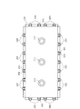
以下、本発明の実施の形態を添付図面を参照して説明する。図1は、本発明のラミネート装置100の要部の構成を示す断面図で、ダイヤフラムをクランプする前の図、図2はクランプした状態を示す断面図で、図3は、ダイヤフラムを取り付けた上チャンバの平面図である。
Embodiments of the present invention will be described below with reference to the accompanying drawings. FIG. 1 is a cross-sectional view showing a configuration of a main part of a
ラミネート装置100は、上チャンバ110と下チャンバ120とを有する。上チャンバ110の下面113及び下チャンバ120の上面122は共に同じ大きさの矩形である。上チャンバ110の上には、図示しない真空ポンプに、接続する3つの吸引口111があり、下チャンバ120の下方には、平面図は図示しないが、同じく3つの吸引口121が設けられている。また、下チャンバ120の内部空間には、支持台130が設けられている。
The
ダイヤフラムの取り付け方は、次の通りである。まず、上チャンバ110を上方に上げ、下チャンバ120の上にダイヤフラム140を拡げて載せる。ダイヤフラム140は下チャンバ120より縦横とも大きいので、その周辺は下チャンバ120の外側にはみ出た状態となる。ダイヤフラム140を拡げて載せたら、下チャンバ120の上に、上チャンバ110を降下させる。ダイヤフラム140は、上チャンバ110と下チャンバ120との重なり部から外側にはみ出した状態となる。このとき、上チャンバ110のクランプ160は開放された状態にしておく。
The method for attaching the diaphragm is as follows. First, the
クランプ160は、操作レバー161と、この操作レバー161より小さい押圧レバー162とを有し、押圧レバー162には、押圧ボルト163が設けられている。押圧ボルト163の長さを調整することで、押圧力を加減することができる。環状バネ164については、後述する。
The
図1の状態で、ダイヤフラム140の下チャンバ120からはみ出た部分を折り曲げて、上チャンバ110の側面112に重ねる。
In the state shown in FIG. 1, the portion protruding from the
次に、クランプ160の操作レバー161を矢印方向に回転する。すると、リンク機構によって押圧レバー162も一緒に矢印方向に回転し、操作レバー161が図2に示す垂直位置になると、押圧ボルト163の先端がダイヤフラム140を上チャンバ110の側面112に押圧し、固定する。操作レバー161が垂直になったら、環状バネ164を掛けて、操作レバー161を垂直位置に付勢する。これによって、操作レバー161が意に反してアンロック位置に回転することを防止することができる。
Next, the
図3に示すように、クランプ160は、上チャンバ110の対向する長辺上および短辺上に多数設けられており、これらを全て図2に示すクランプ状態にすることで、ダイヤフラム140は上チャンバ110に固定される。
As shown in FIG. 3, a large number of
本発明のラミネート装置では、ダイヤフラム140を上チャンバ110に取り付けるのに取付枠を必要としていない。そして、クランプ160は、操作レバー161を回転操作することで、ワンタッチでクランプ状態とアンクランプ状態とに切替でき、非常に簡単である。以上の構成により、ダイヤフラム140を上チャンバ110に簡単に取り付け、取外しができるようになった。
In the laminating apparatus of the present invention, no attachment frame is required to attach the
ダイヤフラム140は上チャンバ110の側面112で固定されるが、下面は全く拘束されていない。したがって、ダイヤフラム140は、自然状態では、図2に示すように、中央で垂れ下がった状態になる。上チャンバ110の下面113には、溝内にOリング170があり、これによって、上チャンバ110とダイヤフラム140との間を気密に保持することができる。
The
この実施例では、上チャンバ110の短辺、長辺ともにクランプ160を設けている。ただしダイヤフラムの大きさが小さい場合や、軽い場合は短辺のクランプを設けなくても良い。
In this embodiment, the
その理由は、上チャンバ110を下チャンバ120上に載せた状態で上チャンバ110の吸引口111から真空ポンプで上チャンバ110内を減圧すると、ダイヤフラム140の大きさが小さい場合や、軽い場合は、短辺部分では上チャンバ110の下面113に吸着され、隙間が無くなる。僅かな漏れがあっても、真空ポンプで引き続けることで、所定の減圧度を保持するのは容易である。
The reason is that when the
なお、真空ポンプはその性格上、通常、予定の圧まで減圧されても停止させることはなく、運転状態を継続している。予定の圧に達した後、漏れがある場合と無い場合を比較すると、漏れがある方が真空ポンプの負荷が若干増加することになる。しかし、殆ど問題にならないレベルの増加に過ぎない。 Note that the vacuum pump normally does not stop even if the vacuum pump is depressurized to a predetermined pressure, and continues to operate. Comparing the case where there is a leak and the case where there is no leak after reaching the predetermined pressure, the load on the vacuum pump slightly increases when there is a leak. However, it is only an increase of the level that hardly becomes a problem.
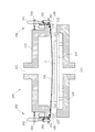
図4は、上チャンバ110と下チャンバ120とを重ね合わせ、支持台130上の被加工物Aを加熱している状態を示す図である。
FIG. 4 is a diagram illustrating a state where the
本発明による太陽電池パネルのラミネート加工の仕方を図4により説明する。被加工物Aとしての太陽電池パネルは、複数の太陽電池セルを接続したストリングを、下側に配置された透明なカバーガラスと上側に配置された裏面材の間に、充填材を介してサンドイッチにした構成である。裏面材としては例えばポリエチレン樹脂などの透明な材料が使用される。充填材には例えばEVA(エチレンビニルアセテート)樹脂などが使用される。 A method of laminating a solar cell panel according to the present invention will be described with reference to FIG. A solar panel as a workpiece A includes a string in which a plurality of solar cells are connected, sandwiched between a transparent cover glass arranged on the lower side and a back material arranged on the upper side via a filler. It is the composition made. As the back material, for example, a transparent material such as polyethylene resin is used. For example, EVA (ethylene vinyl acetate) resin or the like is used as the filler.
上チャンバ110が下チャンバ120の上方の待機位置にあるとき、被加工物Aを搬送ベルト200で搬送し、支持台130の上に達したら、搬送ベルト200を停止させる。また、ダイヤフラム140と被加工物Aとの間には、剥離シート210を介在させている。剥離シート210によって、被加工物A内の充填材が、溶融したときダイヤフラム140に付着しないようにするためである。
When the
支持台130上に被加工物Aが載置されたら、上チャンバ110が降下して下チャンバ120に密着する。下チャンバ120と搬送ベルト200との間は、Oリング170で気密に保持される。そして、吸引口111と121からダイヤフラム140で仕切られた上下の空間内の空気が吸引され、減圧される。上下の空間が所定の圧力まで降下すると、支持台130に内蔵されている熱板が被加工物Aを加熱する。同時に、上チャンバ110内を大気圧に戻す。すると、ダイヤフラム140は、図4に示すように、被加工物Aの外形に沿って膨潤し、被加工物Aを押圧する。この状態で被加工物Aは加熱され、充填材が溶融して架橋反応を起こし、透明になり、太陽電池パネルとなる。
When the workpiece A is placed on the
図4に示すようにダイヤフラム140が膨潤したとき、上下のチャンバ110、120で挟まれたダイヤフラム140の周辺部は、内側に引っ張られ、Oリング170も変形を受ける。従来の取付枠で押さえる形式では、ダイヤフラムが膨潤する時にできたOリングの変形は、ラミネート加工を繰り返すことで、徐々に蓄積され、大きく変形してやがて破損に至るものであった。
As shown in FIG. 4, when the
しかし、本発明では、ラミネート加工が終了すると、上チャンバ110は図2に示すように上方に待機し、ダイヤフラム140は、中央部がやや垂れ下がった自然状態になる。ダイヤフラム140が自由状態に戻るので、Oリング170もラミネート加工時に受けていた変形が消滅し、初期の状態に復帰する。したがって、本発明では、ラミネート加工を繰り返しても、Oリング170の変形は蓄積されることはなく、常に、1回の変形を受けるだけになる。そのため、Oリング170の寿命は永くなる。また、ダイヤフラム140も、ラミネート加工中に、上下のチャンバ110、120で挟まれていた部分が変形をするが、この変形も、図2の状態になったとき、消滅するので、変形が蓄積することがない。さらに、本発明では、ダイヤフラム140を折り曲げて、上チャンバ110の側面で把持するので、把持力が大きい。従来は、膨潤したとき引張力が加わる平面内で圧接により保持していたので、ダイヤフラムの端部がチャンバ内に引き込まれ、真空が破れるということがあったが、本発明では、そのようなことは生じなくなった。
However, in the present invention, when the laminating process is completed, the
図5は、本発明の第2実施例を示す断面図である。この実施例では、クランプ160の押圧ボルト163とダイヤフラム140との間に、板材165を挿入している。板材165で押圧することで、ダイヤフラム140を面で押圧することができ、真空漏れを防止し易くなる。板材165の長さは、任意でよいが、複数のクランプ160を跨ぐ長さにすることで、上チャンバ110の1つの長辺全体で、ダイヤフラム140を押圧することができ、真空漏れをより確実に防止することができる。板材165には、金属製のアングル材を使用してもよい。
FIG. 5 is a sectional view showing a second embodiment of the present invention. In this embodiment, a
なお、板材165は、ダイヤフラム140の交換に際してクランプ160をアンクランプするので、落下しないように、クランプ160の押圧ボルト163に接続するなどの構成とすることが好ましい。
Since the
100 ラミネート装置
110 上チャンバ
112 側面
113 下面
120 下チャンバ
130 支持台
140 ダイヤフラム
160 クランプ
100
Claims (4)
Priority Applications (9)
| Application Number | Priority Date | Filing Date | Title |
|---|---|---|---|
| JP2007155801A JP2008307724A (en) | 2007-06-13 | 2007-06-13 | Laminator |
| US12/155,493 US7726375B2 (en) | 2007-06-13 | 2008-06-05 | Laminator |
| KR1020080054015A KR20080109628A (en) | 2007-06-13 | 2008-06-10 | Laminating apparatus |
| TW097121801A TW200908362A (en) | 2007-06-13 | 2008-06-11 | Laminator |
| ES08158174T ES2363742T3 (en) | 2007-06-13 | 2008-06-12 | LAMINATOR |
| EP08158174A EP2014454B1 (en) | 2007-06-13 | 2008-06-12 | Laminator |
| AT08158174T ATE502763T1 (en) | 2007-06-13 | 2008-06-12 | COATER |
| DE602008005673T DE602008005673D1 (en) | 2007-06-13 | 2008-06-12 | coaters |
| CNA2008101254461A CN101323196A (en) | 2007-06-13 | 2008-06-13 | Laminator |
Applications Claiming Priority (1)
| Application Number | Priority Date | Filing Date | Title |
|---|---|---|---|
| JP2007155801A JP2008307724A (en) | 2007-06-13 | 2007-06-13 | Laminator |
Publications (1)
| Publication Number | Publication Date |
|---|---|
| JP2008307724A true JP2008307724A (en) | 2008-12-25 |
Family
ID=39744766
Family Applications (1)
| Application Number | Title | Priority Date | Filing Date |
|---|---|---|---|
| JP2007155801A Pending JP2008307724A (en) | 2007-06-13 | 2007-06-13 | Laminator |
Country Status (9)
| Country | Link |
|---|---|
| US (1) | US7726375B2 (en) |
| EP (1) | EP2014454B1 (en) |
| JP (1) | JP2008307724A (en) |
| KR (1) | KR20080109628A (en) |
| CN (1) | CN101323196A (en) |
| AT (1) | ATE502763T1 (en) |
| DE (1) | DE602008005673D1 (en) |
| ES (1) | ES2363742T3 (en) |
| TW (1) | TW200908362A (en) |
Cited By (4)
| Publication number | Priority date | Publication date | Assignee | Title |
|---|---|---|---|---|
| JP2010052387A (en) * | 2008-08-29 | 2010-03-11 | Npc Inc | Laminating device, and method for mounting diaphragm in laminating device |
| CN102069627A (en) * | 2010-11-14 | 2011-05-25 | 嘉友联精密机械工程(无锡)有限公司 | Full-automatic solar cell module laminator |
| JP2015188107A (en) * | 2008-01-18 | 2015-10-29 | ロックウェル・コリンズ・インコーポレーテッド | Substrate lamination system and method |
| JP7341457B2 (en) | 2019-07-23 | 2023-09-11 | 新光エンジニアリング株式会社 | Work pasting device |
Families Citing this family (6)
| Publication number | Priority date | Publication date | Assignee | Title |
|---|---|---|---|---|
| CN102470659B (en) | 2009-08-13 | 2014-10-22 | 陶氏环球技术有限责任公司 | A multi-layer laminate structure and manufacturing method |
| KR101146916B1 (en) * | 2010-09-17 | 2012-05-23 | (주)와이에스썸텍 | Laminate Apparatus for Set-Up of Diaphragm |
| CN103348493B (en) | 2010-12-17 | 2016-01-27 | 陶氏环球技术有限责任公司 | The photovoltaic device of improvement |
| CN102179987A (en) * | 2011-03-04 | 2011-09-14 | 浙江长兴亚金机械有限公司 | Sealing structure of solar laminating machine |
| CN105015130B (en) * | 2015-08-04 | 2019-04-02 | 四川杰邦科技有限公司 | A kind of positive/negative-pressure vacuum coating machines |
| KR102215257B1 (en) * | 2020-09-11 | 2021-02-15 | 한화솔루션 주식회사 | Diaphragm sheet for solar cell module laminating process and laminating apparatus including the same |
Citations (9)
| Publication number | Priority date | Publication date | Assignee | Title |
|---|---|---|---|---|
| DE3017273A1 (en) * | 1980-05-06 | 1981-11-12 | Helmut Friz Gmbh & Co, 7102 Weinsberg | Diaphragm press for veneering panels - has diaphragm tensioned by hydraulic cylinders or pneumatic tubes around edge of heated pressure plate |
| JPH0531743A (en) * | 1991-08-02 | 1993-02-09 | Dainippon Printing Co Ltd | Vacuum press laminate molding method and its device |
| JPH05293896A (en) * | 1992-04-20 | 1993-11-09 | Dainippon Printing Co Ltd | Device for laminated molding with vacuum press |
| JPH05293895A (en) * | 1992-04-20 | 1993-11-09 | Dainippon Printing Co Ltd | Device and method for laminated molding with vacuum press |
| JP3025078U (en) * | 1995-11-22 | 1996-06-07 | 博 村上 | Grasping transport device |
| JPH091664A (en) * | 1995-06-19 | 1997-01-07 | Gr Syst | Method and apparatus for joining laminated thermoplastic sheet material |
| JP2000254852A (en) * | 1999-03-08 | 2000-09-19 | Ryobi Ltd | Clamping device for sander |
| JP2002347115A (en) * | 2001-05-22 | 2002-12-04 | Nisshinbo Ind Inc | Method for attaching diaphragm in laminate apparatus and laminate apparatus using the method |
| JP2007054888A (en) * | 2005-07-04 | 2007-03-08 | Meier Vakuumtechnik Gmbh | Membrane press |
Family Cites Families (14)
| Publication number | Priority date | Publication date | Assignee | Title |
|---|---|---|---|---|
| US2575734A (en) * | 1947-12-30 | 1951-11-20 | Westinghouse Electric Corp | Press |
| JPS5810182B2 (en) | 1979-06-04 | 1983-02-24 | 日立精機株式会社 | Machine tool with tool changer |
| DE3322877A1 (en) | 1983-06-24 | 1985-01-10 | Maho Werkzeugmaschinenbau Babel & Co, 8962 Pfronten | MACHINING CENTER FOR MILLING AND BORING |
| JPS62176723A (en) | 1986-01-30 | 1987-08-03 | Yamazaki Mazak Corp | Flexible tool magazine |
| DE3607391A1 (en) | 1986-03-06 | 1987-09-10 | Maho Ag | TOOL TROLLEY FOR LOADING MACHINE TOOLS |
| US4699276A (en) * | 1986-07-31 | 1987-10-13 | Kearney & Trecker Corporation | Chain-type tool storage magazine |
| JPH0337201A (en) | 1989-07-04 | 1991-02-18 | Sekisui Plastics Co Ltd | Production of elastic acrylic particle |
| JPH09141743A (en) | 1995-11-24 | 1997-06-03 | N P C:Kk | Lamination apparatus |
| JP3037201U (en) | 1996-10-25 | 1997-05-16 | 株式会社エヌ・ピー・シー | Laminating equipment |
| JP3655076B2 (en) | 1998-01-07 | 2005-06-02 | 株式会社エヌ・ピー・シー | Laminating equipment |
| DE10163294B4 (en) | 2001-12-21 | 2010-09-09 | Deckel Maho Geretsried Gmbh | Tool change system for program-controlled milling and drilling machines |
| JP3964851B2 (en) | 2003-10-21 | 2007-08-22 | ヤマザキマザック株式会社 | Horizontal machining center |
| US7488242B2 (en) * | 2005-03-14 | 2009-02-10 | Allway Tools, Inc. | Sanding apparatus with molded elastomeric pad |
| JP2007155801A (en) | 2005-11-30 | 2007-06-21 | Mitsumi Electric Co Ltd | Camera module |
-
2007
- 2007-06-13 JP JP2007155801A patent/JP2008307724A/en active Pending
-
2008
- 2008-06-05 US US12/155,493 patent/US7726375B2/en not_active Expired - Fee Related
- 2008-06-10 KR KR1020080054015A patent/KR20080109628A/en not_active Application Discontinuation
- 2008-06-11 TW TW097121801A patent/TW200908362A/en unknown
- 2008-06-12 DE DE602008005673T patent/DE602008005673D1/en active Active
- 2008-06-12 AT AT08158174T patent/ATE502763T1/en not_active IP Right Cessation
- 2008-06-12 ES ES08158174T patent/ES2363742T3/en active Active
- 2008-06-12 EP EP08158174A patent/EP2014454B1/en not_active Not-in-force
- 2008-06-13 CN CNA2008101254461A patent/CN101323196A/en active Pending
Patent Citations (9)
| Publication number | Priority date | Publication date | Assignee | Title |
|---|---|---|---|---|
| DE3017273A1 (en) * | 1980-05-06 | 1981-11-12 | Helmut Friz Gmbh & Co, 7102 Weinsberg | Diaphragm press for veneering panels - has diaphragm tensioned by hydraulic cylinders or pneumatic tubes around edge of heated pressure plate |
| JPH0531743A (en) * | 1991-08-02 | 1993-02-09 | Dainippon Printing Co Ltd | Vacuum press laminate molding method and its device |
| JPH05293896A (en) * | 1992-04-20 | 1993-11-09 | Dainippon Printing Co Ltd | Device for laminated molding with vacuum press |
| JPH05293895A (en) * | 1992-04-20 | 1993-11-09 | Dainippon Printing Co Ltd | Device and method for laminated molding with vacuum press |
| JPH091664A (en) * | 1995-06-19 | 1997-01-07 | Gr Syst | Method and apparatus for joining laminated thermoplastic sheet material |
| JP3025078U (en) * | 1995-11-22 | 1996-06-07 | 博 村上 | Grasping transport device |
| JP2000254852A (en) * | 1999-03-08 | 2000-09-19 | Ryobi Ltd | Clamping device for sander |
| JP2002347115A (en) * | 2001-05-22 | 2002-12-04 | Nisshinbo Ind Inc | Method for attaching diaphragm in laminate apparatus and laminate apparatus using the method |
| JP2007054888A (en) * | 2005-07-04 | 2007-03-08 | Meier Vakuumtechnik Gmbh | Membrane press |
Cited By (4)
| Publication number | Priority date | Publication date | Assignee | Title |
|---|---|---|---|---|
| JP2015188107A (en) * | 2008-01-18 | 2015-10-29 | ロックウェル・コリンズ・インコーポレーテッド | Substrate lamination system and method |
| JP2010052387A (en) * | 2008-08-29 | 2010-03-11 | Npc Inc | Laminating device, and method for mounting diaphragm in laminating device |
| CN102069627A (en) * | 2010-11-14 | 2011-05-25 | 嘉友联精密机械工程(无锡)有限公司 | Full-automatic solar cell module laminator |
| JP7341457B2 (en) | 2019-07-23 | 2023-09-11 | 新光エンジニアリング株式会社 | Work pasting device |
Also Published As
| Publication number | Publication date |
|---|---|
| KR20080109628A (en) | 2008-12-17 |
| US7726375B2 (en) | 2010-06-01 |
| US20090000747A1 (en) | 2009-01-01 |
| EP2014454B1 (en) | 2011-03-23 |
| EP2014454A1 (en) | 2009-01-14 |
| DE602008005673D1 (en) | 2011-05-05 |
| TW200908362A (en) | 2009-02-16 |
| CN101323196A (en) | 2008-12-17 |
| ES2363742T3 (en) | 2011-08-12 |
| ATE502763T1 (en) | 2011-04-15 |
Similar Documents
| Publication | Publication Date | Title |
|---|---|---|
| JP2008307724A (en) | Laminator | |
| JP2008126407A (en) | Laminator | |
| JP5209229B2 (en) | Manufacturing method of solar cell module | |
| JP4308769B2 (en) | Laminating equipment | |
| JP2007123451A (en) | Manufacturing method of solar cell module | |
| JP2009039862A (en) | Vacuum forming apparatus and vacuum forming method | |
| JP2002347115A (en) | Method for attaching diaphragm in laminate apparatus and laminate apparatus using the method | |
| WO2019080520A1 (en) | Laminating device | |
| JP4773938B2 (en) | Solar cell module laminating equipment. | |
| JP5128687B2 (en) | Manufacturing method of solar cell module, and solar cell module manufactured by the manufacturing method | |
| KR101534023B1 (en) | Laminating System and Method | |
| JP5470341B2 (en) | Manufacturing method of solar cell module | |
| JP2007112031A (en) | Apparatus and method for lamination | |
| JP2006021856A (en) | Sheet conveying device, sheet conveying method, and solar cell module manufacturing method using the method | |
| JP2015100941A (en) | Fitting jig of diaphragm for laminating apparatus, and fitting method of diaphragm | |
| JP4842306B2 (en) | Laminating apparatus and method of attaching diaphragm in laminating apparatus | |
| KR20210091765A (en) | Lamination apparatus and method therefor | |
| JP2011251422A (en) | Decorating apparatus | |
| JP2008194947A (en) | Laminating apparatus | |
| JP4347454B2 (en) | Method for sealing solar cell module | |
| KR101146916B1 (en) | Laminate Apparatus for Set-Up of Diaphragm | |
| JP5033840B2 (en) | Laminating method and apparatus for producing solar cell panel | |
| JP2016125605A (en) | Drawing-in prevention jig of diaphragm for laminate device | |
| JP2010192638A (en) | Laminating device | |
| CN112895417B (en) | PE protective film for pasting mobile phone glass cover plate |
Legal Events
| Date | Code | Title | Description |
|---|---|---|---|
| A621 | Written request for application examination |
Free format text: JAPANESE INTERMEDIATE CODE: A621 Effective date: 20100430 |
|
| A977 | Report on retrieval |
Free format text: JAPANESE INTERMEDIATE CODE: A971007 Effective date: 20120210 |
|
| A131 | Notification of reasons for refusal |
Free format text: JAPANESE INTERMEDIATE CODE: A131 Effective date: 20120221 |
|
| A521 | Request for written amendment filed |
Free format text: JAPANESE INTERMEDIATE CODE: A523 Effective date: 20120420 |
|
| A131 | Notification of reasons for refusal |
Free format text: JAPANESE INTERMEDIATE CODE: A131 Effective date: 20121106 |
|
| A02 | Decision of refusal |
Free format text: JAPANESE INTERMEDIATE CODE: A02 Effective date: 20130312 |