JP4682014B2 - Manufacturing method of solar cell module - Google Patents

Manufacturing method of solar cell module Download PDF

Info

Publication number
JP4682014B2
JP4682014B2 JP2005312032A JP2005312032A JP4682014B2 JP 4682014 B2 JP4682014 B2 JP 4682014B2 JP 2005312032 A JP2005312032 A JP 2005312032A JP 2005312032 A JP2005312032 A JP 2005312032A JP 4682014 B2 JP4682014 B2 JP 4682014B2
Authority
JP
Japan
Prior art keywords
sealing
film
substrate
sealing resin
solar cell
Prior art date
Legal status (The legal status is an assumption and is not a legal conclusion. Google has not performed a legal analysis and makes no representation as to the accuracy of the status listed.)
Expired - Fee Related
Application number
JP2005312032A
Other languages
Japanese (ja)
Other versions
JP2007123451A (en
JP2007123451A5 (en
Inventor
健 勇木
勝 秋山
圭三 政田
Current Assignee (The listed assignees may be inaccurate. Google has not performed a legal analysis and makes no representation or warranty as to the accuracy of the list.)
Nakajima Glass Co Inc
Original Assignee
Nakajima Glass Co Inc
Priority date (The priority date is an assumption and is not a legal conclusion. Google has not performed a legal analysis and makes no representation as to the accuracy of the date listed.)
Filing date
Publication date
Application filed by Nakajima Glass Co Inc filed Critical Nakajima Glass Co Inc
Priority to JP2005312032A priority Critical patent/JP4682014B2/en
Publication of JP2007123451A publication Critical patent/JP2007123451A/en
Publication of JP2007123451A5 publication Critical patent/JP2007123451A5/ja
Application granted granted Critical
Publication of JP4682014B2 publication Critical patent/JP4682014B2/en
Expired - Fee Related legal-status Critical Current
Anticipated expiration legal-status Critical

Links

Images

Classifications

    • YGENERAL TAGGING OF NEW TECHNOLOGICAL DEVELOPMENTS; GENERAL TAGGING OF CROSS-SECTIONAL TECHNOLOGIES SPANNING OVER SEVERAL SECTIONS OF THE IPC; TECHNICAL SUBJECTS COVERED BY FORMER USPC CROSS-REFERENCE ART COLLECTIONS [XRACs] AND DIGESTS
    • Y02TECHNOLOGIES OR APPLICATIONS FOR MITIGATION OR ADAPTATION AGAINST CLIMATE CHANGE
    • Y02EREDUCTION OF GREENHOUSE GAS [GHG] EMISSIONS, RELATED TO ENERGY GENERATION, TRANSMISSION OR DISTRIBUTION
    • Y02E10/00Energy generation through renewable energy sources
    • Y02E10/50Photovoltaic [PV] energy

Landscapes

  • Photovoltaic Devices (AREA)

Description

本発明は、太陽電池モジュールの製造方法に関する。特に、基板とフィルムとの間に太陽電池セルが樹脂で封止されてなる太陽電池モジュールの製造方法に関する。   The present invention relates to a method for manufacturing a solar cell module. In particular, the present invention relates to a method for manufacturing a solar cell module in which solar cells are sealed with a resin between a substrate and a film.

近年、環境保護の意識が高まり、太陽光発電はその重要性を一段と増している。太陽電池セルは、保護材で挟まれ、透明樹脂で封止されて太陽電池モジュールとして屋外で使用される。封止のための透明樹脂としては、エチレン−酢酸ビニル共重合体(以下、EVAと略することがある。)樹脂などが使用されており、それを保護材と太陽電池セルの間に挟んで、加熱溶融してから固化させることで封止している。太陽電池セルを効率的に配置して配線するためには、複数の太陽電池セルを一つの太陽電池モジュール内に封止することが好ましい。   In recent years, awareness of environmental protection has increased, and solar power generation has become even more important. The solar battery cell is sandwiched between protective materials, sealed with a transparent resin, and used outdoors as a solar battery module. As a transparent resin for sealing, an ethylene-vinyl acetate copolymer (hereinafter abbreviated as EVA) resin or the like is used, which is sandwiched between a protective material and a solar battery cell. It is sealed by solidifying after heating and melting. In order to arrange and wire solar cells efficiently, it is preferable to seal a plurality of solar cells in one solar cell module.

複数の太陽電池セルを太陽電池モジュール内に封止する方法としては、主として、二重真空室方式のラミネーターを使用する方法と、一重真空室方式のラミネーターを使用する方法とが知られている。二重真空室方式のラミネーターは、気体非透過性の柔軟なシートで隔てられた二室の真空度をそれぞれ独立に調整できるために、封止時に気泡の残留やセル割れを抑制できるが、ラミネーターの構造が複雑である。一方、一重真空方式のラミネーターは気泡の残留やセル割れが発生しやすいが、ラミネーターの構造が簡単である。これらのラミネーターは、太陽電池モジュールの仕様によって使い分けられている。多くの場合、上記いずれのラミネーターにおいても、ヒーターを内蔵したプレートの上に積層体を載せて、当該積層体の存在する空間を真空にしながら、加熱を施して封止している。   As a method for sealing a plurality of solar cells in a solar cell module, a method using a double vacuum chamber type laminator and a method using a single vacuum chamber type laminator are mainly known. The double vacuum chamber type laminator is capable of independently adjusting the degree of vacuum in the two chambers separated by a gas-impermeable flexible sheet. The structure is complicated. On the other hand, a single vacuum type laminator tends to cause residual bubbles and cell cracking, but the laminator structure is simple. These laminators are properly used according to the specifications of the solar cell module. In many cases, in any of the above laminators, a laminate is placed on a plate incorporating a heater, and the space in which the laminate is present is heated and sealed while being evacuated.

基板とフィルムとの間に太陽電池セルが樹脂で封止されてなる構造の太陽電池モジュールは、前述の各種のラミネーターを用いて大量に生産されている。しかしながら、フィルムは柔軟であるために、得られたモジュールにおいて、その表面を平滑にするのが困難であった。   Solar cell modules having a structure in which solar cells are sealed with resin between a substrate and a film are produced in large quantities using the various laminators described above. However, since the film is flexible, it has been difficult to smooth the surface of the obtained module.

特許文献1には、薄膜太陽電池の受光面側にシート状の封止接着剤と表面保護材、非受光面側に封止接着剤と裏面補強材を重ね合わせて一体にラミネートした太陽電池モジュールの製造方法であって、基板の周囲を脱気用枠体で囲み、その上に柔軟なダイヤフラムを被せた構成になる真空ラミネート装置を使用し、該装置の基板と枠体とダイヤフラムとで囲まれたラミネート処理空間内に前記のモジュール構成材料を重ね合わせて配置した上で、ラミネート処理空間を真空引きおよび加熱してラミネート処理を行う際に、前記の真空ラミネート装置に対して、薄膜太陽電池の受光面を上に向けたフェースアップ積層でモジュール構成材料をラミネート処理空間内に配置するとともに、その最受光面側に剛性を有する平坦な当て板材を押し当ててラミネート処理を行うことを特徴とする太陽電池モジュールの製造方法が記載されている。これによって、太陽電池モジュールの受光面を平坦面に仕上げることができるとされている。   Patent Document 1 discloses a solar cell module in which a sheet-like sealing adhesive and a surface protective material are laminated on the light-receiving surface side of a thin film solar cell, and a sealing adhesive and a back surface reinforcing material are laminated on the non-light-receiving surface side. A vacuum laminating apparatus in which a substrate is surrounded by a deaeration frame and a flexible diaphragm is covered on the substrate, and the apparatus is surrounded by the substrate, the frame, and the diaphragm. A thin film solar cell is used for the vacuum laminating apparatus when the laminating process is performed by evacuating and heating the laminating space after the module constituent materials are placed in the laminated laminating space. The module constituent material is placed in the laminating space by face-up lamination with the light receiving surface facing up, and a flat, rigid plate is pressed against the light receiving surface. Method of manufacturing a solar cell module, which comprises carrying out the laminating process is described. Thus, the light receiving surface of the solar cell module can be finished to a flat surface.

しかしながら実際には、特許文献1記載の方法のようにフィルム側を平坦な板で押さえても、得られるモジュールのフィルム表面を平坦にすることは容易ではなかった。封止操作時において、封止されるセルや配線に由来する凹凸や、局所的に発生する圧力差や、加熱によるフィルムの収縮などによってフィルムにシワが発生したり、フィルム表面に凹凸が形成されたりすることが多かった。特に美麗な外観が求められる用途においては、表面の高度な平滑性が要求される場合があり、それを可能にする封止方法が求められている。   However, in practice, even if the film side is pressed with a flat plate as in the method described in Patent Document 1, it is not easy to flatten the film surface of the obtained module. During the sealing operation, wrinkles occur in the film due to unevenness originating from the cells and wiring to be sealed, pressure difference generated locally, shrinkage of the film due to heating, etc., and unevenness is formed on the film surface There were many times. In particular, in applications where a beautiful appearance is required, high smoothness of the surface may be required, and a sealing method that enables this is required.

一方、特許文献2には、受光面側透明板と裏面板との間に複数の太陽電池セルが樹脂で封止されてなる太陽電池モジュールの製造方法において、複数の太陽電池セルを所定の間隔をあけて配列して相互に導線で接続し、受光面側透明板と太陽電池セルの間に受光面側透明板の実質的に全面を覆う第1封止樹脂シートを配置し、裏面板と太陽電池セルの間に裏面板の実質的に全面を覆う第2封止樹脂シートを配置し、太陽電池セル間の間隙部には第1封止樹脂シートと第2封止樹脂シートで挟持されるように太陽電池セルの厚みよりも厚い封止樹脂シート片を配置してから、受光面側透明板と裏面板との間の空気を排出し、加熱して樹脂を溶融させてから冷却して封止することを特徴とする太陽電池モジュールの製造方法が記載されており、複数の太陽電池セルを配列して樹脂で封止する際に、太陽電池セルの破損を防止することができるとされている。   On the other hand, in Patent Document 2, in a method for manufacturing a solar cell module in which a plurality of solar cells are sealed with a resin between a light-receiving surface side transparent plate and a back plate, the plurality of solar cells are arranged at predetermined intervals. The first sealing resin sheet covering the substantially entire surface of the light-receiving surface side transparent plate is disposed between the light-receiving surface side transparent plate and the solar battery cell, A second sealing resin sheet that covers substantially the entire surface of the back plate is disposed between the solar cells, and is sandwiched between the first sealing resin sheet and the second sealing resin sheet in the gap between the solar cells. After placing a sealing resin sheet piece thicker than the thickness of the solar battery cell, discharge the air between the light-receiving surface side transparent plate and the back plate, heat it to melt the resin, and then cool it A method of manufacturing a solar cell module characterized in that By arranging the solar cell on the time of sealing with resin, it is to be able to prevent damage to the solar cells.

特開2004−311571号公報Japanese Patent Laid-Open No. 2004-311571 国際公開第2004/038811号パンフレットInternational Publication No. 2004/038811 Pamphlet

本発明は、上記課題を解決するためになされたものであり、基板とフィルムとの間に太陽電池セルが樹脂で封止され、当該フィルムの表面が極めて平滑な太陽電池モジュールを製造する方法を提供することを目的とするものである。   The present invention has been made in order to solve the above problems, and a method for producing a solar cell module in which solar cells are sealed with a resin between a substrate and a film, and the surface of the film is extremely smooth. It is intended to provide.

上記課題は、基板とフィルムとの間に太陽電池セルが樹脂で封止されてなる太陽電池モジュールの製造方法において、前記基板と前記太陽電池セルとの間に前記基板の実質的に全面を覆う第1封止樹脂シートを配置し、前記フィルムと前記太陽電池セルとの間に前記基板の実質的に全面を覆う第2封止樹脂シートを配置し、前記フィルムの縁部を固定するとともに前記フィルムの外側に該フィルムの実質的に全体を覆うことのできる面積の当て板を配置してから、気体不透過性の柔軟なシートからなる封止処理容器内において、前記基板と前記フィルムとの間の空気を排出し、加熱して樹脂を溶融させてから冷却して封止するに際し、前記フィルムとして熱収縮性を有するフィルムを使用し、該フィルムの縁部を固定することによって封止操作中に収縮しないようにすることを特徴とする太陽電池モジュールの製造方法を提供することによって解決される。 In the method for manufacturing a solar cell module in which solar cells are sealed with a resin between a substrate and a film, the above problem covers substantially the entire surface of the substrate between the substrate and the solar cells. A first sealing resin sheet is disposed, a second sealing resin sheet covering substantially the entire surface of the substrate is disposed between the film and the solar battery cell, and an edge of the film is fixed . In the sealing processing container consisting of a gas-impermeable flexible sheet, a base plate having an area capable of covering substantially the entire film is disposed outside the film, and the substrate, the film, air emissions during, upon heating to melt the resin for sealing then cooled, using a film having a heat-shrinkable as the film, sealing by fixing the edges of the film Is solved by providing a method of manufacturing a solar cell module, characterized in that to avoid shrinkage in Sakuchu.

このとき、前記基板の厚みが2〜25mmであり、フィルムの厚みが0.01〜0.3mmであることが好ましい。前記基板が湾曲していて、前記当て板が前記基板と実質的に同じ曲率で湾曲していることが、本発明の好適な実施態様である At this time, it is preferable that the thickness of the substrate is 2 to 25 mm and the thickness of the film is 0.01 to 0.3 mm. In a preferred embodiment of the present invention, the substrate is curved and the contact plate is curved with substantially the same curvature as the substrate .

前記封止樹脂が、エチレン−酢酸ビニル共重合体、ポリビニルブチラール及びポリウレタンからなる群から選択される一種の樹脂であることが好適である。複数の太陽電池セルを間隔をあけて配列して相互に導線で接続して封止することが本発明の好適な実施態様である。太陽電池セル間の間隙部又は太陽電池セルの外側の余白部に、太陽電池セルの厚みよりも厚い封止樹脂シート片を配置することが好適である。このとき、前記封止樹脂シート片相互の間に間隔をあけて配置し、そこから内部の空気を排出することがより好適である。   It is preferable that the sealing resin is a kind of resin selected from the group consisting of ethylene-vinyl acetate copolymer, polyvinyl butyral, and polyurethane. It is a preferred embodiment of the present invention that a plurality of solar cells are arranged at intervals and are connected to each other by conducting wires and sealed. It is preferable to dispose a sealing resin sheet piece that is thicker than the thickness of the solar battery cell in the gap between the solar battery cells or in the blank space outside the solar battery cell. At this time, it is more preferable that the sealing resin sheet pieces are arranged with a space between them and the internal air is discharged therefrom.

前記フィルムの縁部を前記当て板、前記基板又は枠体に固定することが好適な実施態様であるまた、複数の太陽電池モジュールを重ねて同時に封止し、その際、前記フィルムの縁部を前記基板に固定するとともに、隣接する太陽電池モジュールの基板を前記当て板として使用することも好適な実施態様である。 The edges of the film, said backing plate, it is a preferred embodiment be secured to the substrate or frame. In addition, it is also preferable that a plurality of solar cell modules are stacked and sealed simultaneously, and at that time, the edge of the film is fixed to the substrate, and the substrate of the adjacent solar cell module is used as the contact plate. It is an aspect.

複数の前記封止処理容器をオーブン内に導入して相互に間隔をあけて平行に配置し、前記オーブン内において前記基板と平行の向きに熱風を流すことによって加熱して封止樹脂を溶融させることが好ましい。また、前記封止処理容器内で封止するに際して、封止樹脂の融点未満の温度において封止処理容器内を減圧する工程(工程2)、減圧したままで封止樹脂の融点以上の温度まで昇温する工程(工程3)、前記封止処理容器内の圧力を上昇させる工程(工程4)、及び冷却する工程(工程6)の各工程からなる封止操作を行うことも好ましい。さらに、前記工程2において封止樹脂の融点未満の温度において封止処理容器内を0.01MPa以下の圧力まで減圧するとともに、該工程2に先立って、封止処理容器内の圧力を0.05MPa以上に保って封止樹脂を加熱する工程(工程1)を有することがより好ましい。 A plurality of the sealing treatment containers are introduced into the oven and arranged parallel to each other with a space therebetween, and the sealing resin is melted by heating by flowing hot air in a direction parallel to the substrate in the oven. It is preferable. Further, when sealing in the sealing processing container, a step of reducing the pressure in the sealing processing container at a temperature lower than the melting point of the sealing resin (step 2), up to a temperature equal to or higher than the melting point of the sealing resin with the pressure reduced. It is also preferable to perform a sealing operation consisting of a step of raising the temperature (step 3), a step of raising the pressure in the sealing treatment container (step 4), and a step of cooling (step 6). Further, in the step 2, the inside of the sealing process container is depressurized to a pressure of 0.01 MPa or less at a temperature lower than the melting point of the sealing resin, and prior to the process 2, the pressure in the sealing process container is set to 0.05 MPa. It is more preferable to have a step (step 1) of heating the sealing resin while maintaining the above.

本発明の製造方法によれば、基板とフィルムとの間に太陽電池セルが樹脂で封止され、当該フィルムの表面が極めて平滑な太陽電池モジュールを製造することができる。   According to the production method of the present invention, a solar battery module in which a solar battery cell is sealed with a resin between a substrate and a film and the surface of the film is extremely smooth can be produced.

以下、図面を用いて本発明を詳細に説明する。図1は封止操作後の太陽電池モジュールの一例の断面模式図である。図2〜4は封止操作前の積層体の一例の断面模式図である。図5は複数のモジュールを同時に封止する場合の封止操作前の積層体の断面模式図である。図6は封止処理装置の一例の模式図である。   Hereinafter, the present invention will be described in detail with reference to the drawings. FIG. 1 is a schematic cross-sectional view of an example of a solar cell module after a sealing operation. 2-4 is a cross-sectional schematic diagram of an example of the laminated body before sealing operation. FIG. 5 is a schematic cross-sectional view of a laminate before a sealing operation in the case of simultaneously sealing a plurality of modules. FIG. 6 is a schematic view of an example of a sealing processing apparatus.

本発明の製造方法によって得られる太陽電池モジュール1は、基板2とフィルム3との間に太陽電池セル4が樹脂5で封止されてなるものである。太陽電池モジュール1中に封止される太陽電池セル4の数は、一つであっても良いが、通常、複数の太陽電池セル4が封止されたものである。通常、隣接する太陽電池セル4の受光面6と裏面7とが、導線8を介して接続される。その場合の断面模式図を図1に示す。この例では、基板2側から光が入射するが、フィルム3側から光が入射しても構わない。   The solar cell module 1 obtained by the manufacturing method of the present invention is obtained by sealing solar cells 4 with a resin 5 between a substrate 2 and a film 3. The number of solar cells 4 sealed in the solar cell module 1 may be one, but usually a plurality of solar cells 4 are sealed. Usually, the light receiving surface 6 and the back surface 7 of the adjacent solar battery cell 4 are connected via the conducting wire 8. A schematic cross-sectional view in that case is shown in FIG. In this example, light is incident from the substrate 2 side, but light may be incident from the film 3 side.

本発明で使用される太陽電池セル4は、単結晶シリコン太陽電池、多結晶シリコン太陽電池、アモルファスシリコン太陽電池、化合物半導体太陽電池、薄膜太陽電池など、各種の太陽電池のセルが使用可能である。ここで、薄膜太陽電池を使用する場合、薄膜が形成された基板全体をセルという。これらの太陽電池セルは一般的には2mm以下、より一般的には1mm以下、さらに一般的には0.5mm以下の厚さの薄板であり、1辺が5cm以上の四角形であることが多い。このとき、四角形の角部が面取りされていることも多い。その基板の材質は、シリコンやゲルマニウム等の半導体基板、ガラス基板、プラスチック基板、金属基板などを使用できるが、シリコン基板が、実用的には最も重要である。シリコン基板の場合、コスト面の要請から薄板化が望まれている一方で、硬くて脆い材質であることから、封止時に特に割れ易く、注意して封止することが必要である。   As the solar battery cell 4 used in the present invention, various solar battery cells such as a single crystal silicon solar battery, a polycrystalline silicon solar battery, an amorphous silicon solar battery, a compound semiconductor solar battery, and a thin film solar battery can be used. . Here, when using a thin film solar cell, the whole board | substrate with which the thin film was formed is called a cell. These solar cells are generally thin plates having a thickness of 2 mm or less, more generally 1 mm or less, and more generally 0.5 mm or less, and are often quadrangular with sides of 5 cm or more. . At this time, the corners of the quadrangle are often chamfered. As the material of the substrate, a semiconductor substrate such as silicon or germanium, a glass substrate, a plastic substrate, a metal substrate, or the like can be used, but the silicon substrate is most important in practical use. In the case of a silicon substrate, thinning is desired from the viewpoint of cost. However, since it is a hard and brittle material, it is particularly easy to break at the time of sealing, and it is necessary to seal it carefully.

1つの太陽電池モジュール1に封入される太陽電池セル4の個数は、特に限定されず、1枚だけであっても良い。その場合には太陽電池セル4から外部への配線が接続されるだけになる。1つの太陽電池モジュール1に封入される太陽電池セル4の個数が多いほど、太陽電池モジュール1全体の寸法が大きくなる。大型の太陽電池モジュール1は、フィルム3の面積も大きくなるので、封止時のシワや凹凸が発生しやすく、本発明の製造方法を採用する実益が大きい。したがって、10個以上、好適には20個以上の太陽電池セル4が一つの太陽電池モジュール1内に配置されることが好ましい。また、多数の太陽電池セル4が封入される場合には、気泡が発生しやすくなるし、封止操作中に太陽電池セル4が移動した場合に、外観上問題になりやすい。また、1つの太陽電池モジュール1に封入される太陽電池セル4の個数が多いほど、太陽電池セル4の破損に由来する不良品率が上昇するので、注意して封止することが必要である。   The number of solar cells 4 enclosed in one solar cell module 1 is not particularly limited, and may be only one. In that case, only the wiring from the solar battery cell 4 to the outside is connected. The larger the number of solar cells 4 enclosed in one solar cell module 1, the larger the overall size of the solar cell module 1. Since the large-sized solar cell module 1 has a large area of the film 3, wrinkles and irregularities are easily generated at the time of sealing, and the practical advantage of employing the manufacturing method of the present invention is great. Accordingly, it is preferable that 10 or more, preferably 20 or more solar cells 4 are arranged in one solar cell module 1. Further, when a large number of solar cells 4 are enclosed, bubbles are likely to be generated, and when the solar cells 4 are moved during the sealing operation, it is likely to cause a problem in appearance. Moreover, since the defective product rate resulting from the failure | damage of the photovoltaic cell 4 increases, so that the number of the photovoltaic cells 4 enclosed with one solar cell module 1 increases, it is necessary to seal carefully. .

隣接する太陽電池セル4間の間隙部9の幅は特に限定されないが、通常0.5mm以上であり、これ以下の場合には隣接する太陽電池セル4同士が接触して封止する際にセルが破損するおそれがある。採光性を優先するのであれば間隙部9を広くすることが好ましく、光の利用効率を優先するのであれば間隙部9を狭くすることが好ましい。用途やデザイン面の要請などによって適当に調整される。   The width of the gap 9 between the adjacent solar cells 4 is not particularly limited, but is usually 0.5 mm or more, and in the case of less than this, the cells when the adjacent solar cells 4 come into contact with each other to be sealed May be damaged. If priority is given to daylighting, the gap 9 is preferably widened, and if priority is given to light utilization efficiency, the gap 9 is preferably narrowed. It is adjusted appropriately according to the usage and design requirements.

複数の太陽電池セル4は、所定の幅を介して配列して相互に導線8で接続される。このとき、隣接する太陽電池セル4同士は、受光面6及び裏面7との間で導線8によって接続され、直列方式で多数の太陽電池セル4が接続される。薄膜太陽電池セルの場合には、受光面6側同士を接続する場合がある。導線8による接続は、ハンダ等の導電性接着剤を用いて行われる。また、発生した電流を効率良く集めるために、受光面6上に導電ペーストなどで集電パターンを形成し、それを導線8と導通させるようにすることも好ましい。さらにまた、隣接しないセル同士や離れた位置にある導線8同士を接続する場合や、基板2やフィルム3に孔を開けて導線8を外部に引き出す場合もある。   The plurality of solar cells 4 are arranged with a predetermined width and are connected to each other by a conductive wire 8. At this time, the adjacent solar battery cells 4 are connected to each other by the conductive wire 8 between the light receiving surface 6 and the back surface 7, and a large number of solar battery cells 4 are connected in series. In the case of a thin film solar cell, the light receiving surfaces 6 may be connected to each other. The connection by the conducting wire 8 is performed using a conductive adhesive such as solder. Further, in order to efficiently collect the generated current, it is also preferable to form a current collection pattern with a conductive paste or the like on the light receiving surface 6 so as to be electrically connected to the conductor 8. Furthermore, there may be a case where non-adjacent cells or conductors 8 located at distant positions are connected, or a hole is formed in the substrate 2 or the film 3 so that the conductor 8 is pulled out.

導線8は、インターコネクタとも呼ばれるものであるが、その材質は特に限定されず、銅線などが使用される。基板2とフィルム3との間に挟み込んで配置するため、薄いリボン状の導線8を使用することが好ましく、その厚みは通常0.5mm以下であり、好適には0.3mm以下である。また普通0.05mm以上である。導線8に予めハンダ等の導電性接着剤が塗布されていることが、接続作業が容易になって好ましい。導線8が接続された状態では、太陽電池セル4の表面から導線8の一番高い部分までの高さは、場所によってバラツキがあるが、接続操作によっては、導線8の厚みよりも0.5mm程度厚くなるところもある。このような厚みムラがフィルム3の表面の凹凸形成の原因になることがあるから、本発明の製造方法を採用することが好ましい。   The conductive wire 8 is also called an interconnector, but the material is not particularly limited, and a copper wire or the like is used. In order to sandwich and arrange between the substrate 2 and the film 3, it is preferable to use a thin ribbon-like lead 8, and the thickness is usually 0.5 mm or less, and preferably 0.3 mm or less. Moreover, it is 0.05 mm or more normally. It is preferable that a conductive adhesive such as solder is applied to the conductive wire 8 in advance because the connection work becomes easy. In the state where the conductive wire 8 is connected, the height from the surface of the solar battery cell 4 to the highest portion of the conductive wire 8 varies depending on the location, but depending on the connection operation, the height is 0.5 mm than the thickness of the conductive wire 8. There are places where it gets thicker. Since such thickness unevenness may cause unevenness on the surface of the film 3, it is preferable to employ the manufacturing method of the present invention.

基板2は、太陽電池モジュール1全体の強度を担うものであり、剛性を有する板状体である。基板2の厚みは、2〜25mmであることが好ましい。薄すぎる場合には、モジュール全体の強度が低下するおそれがあり、より好適には3mm以上である。一方、厚すぎる場合にはモジュール全体の重量が重くなりすぎるおそれがあり、より好適には15mm以下である。基板2の面積は用途によって調整されるが、0.5m以上である場合に本発明の製造方法を採用する実益が大きい。基板2の材質は特に限定されず、ガラス、プラスチック、金属、セラミックスなどを使用することができる。受光面側に使用する場合には、太陽光に対して透明である必要があり、ガラスや、ポリカーボネート樹脂やアクリル樹脂などの透明樹脂を使用することができる。 The board | substrate 2 bears the intensity | strength of the solar cell module 1 whole, and is a plate-shaped body which has rigidity. The thickness of the substrate 2 is preferably 2 to 25 mm. If it is too thin, the strength of the entire module may be reduced, and more preferably 3 mm or more. On the other hand, if it is too thick, the weight of the entire module may become too heavy, and is more preferably 15 mm or less. Although the area of the board | substrate 2 is adjusted with an application, when it is 0.5 m < 2 > or more, the actual profit which employ | adopts the manufacturing method of this invention is large. The material of the board | substrate 2 is not specifically limited, Glass, a plastics, a metal, ceramics etc. can be used. When used on the light receiving surface side, it needs to be transparent to sunlight, and a transparent resin such as glass or polycarbonate resin or acrylic resin can be used.

なかでも、耐久性、硬度、難燃性などを考慮するとガラスを使用することが好ましい。屋外に配置された際に飛来物が衝突するおそれがあるし、広い面積の構造材を構成することもあることから、表面圧縮応力が20MPa以上のガラス板であることが、強度の面から好ましい。また、面積が広い場合には日照などによる温度上昇に伴う熱割れも生じやすいので、この点からも表面圧縮応力が20MPa以上のガラス板を使用することが好適である。ここで、板ガラスの表面圧縮応力は、JIS R3222に準じて測定される値である。表面圧縮応力が20MPa以上のガラス板としては、具体的には、倍強度ガラス、強化ガラス、超強化ガラスなどが挙げられる。倍強度ガラスは表面圧縮応力が通常20〜60MPaのものであり、強化ガラスは表面圧縮応力が通常90〜130MPaのものであり、超強化ガラスは表面圧縮応力が通常180〜250MPaのものである。表面圧縮応力を大きくするほど、強度は向上するが、反りが大きくなりやすく製造コストも大きくなりやすい。また倍強度ガラスは、比較的反りの少ないものを製造しやすく、破損したときに細片になって落下することがない点で好ましい。ガラス板は、用途や目的に応じて選択される。   Of these, glass is preferably used in consideration of durability, hardness, flame retardancy, and the like. From the viewpoint of strength, it is preferable that the glass plate has a surface compressive stress of 20 MPa or more because a flying object may collide when placed outdoors and may constitute a structural material having a large area. . In addition, when the area is large, thermal cracking due to temperature rise due to sunshine or the like is likely to occur. From this point, it is preferable to use a glass plate having a surface compressive stress of 20 MPa or more. Here, the surface compressive stress of the plate glass is a value measured according to JIS R3222. Specific examples of the glass plate having a surface compressive stress of 20 MPa or more include double strength glass, tempered glass, and super tempered glass. Double-strength glass usually has a surface compressive stress of 20 to 60 MPa, tempered glass usually has a surface compressive stress of 90 to 130 MPa, and super-tempered glass usually has a surface compressive stress of 180 to 250 MPa. As the surface compressive stress is increased, the strength is improved, but warpage tends to increase and the manufacturing cost tends to increase. The double-strength glass is preferable in that it is easy to produce a glass with relatively little warpage and does not fall into a small piece when dropped. The glass plate is selected according to the use and purpose.

ガラスの材質は特に限定されず、ソーダライムガラスが好適に使用されるが、なかでも、受光面側に使用される場合には、高透過ガラス(いわゆる白板ガラス)が好適に使用される。高透過ガラスは、鉄分の含有量の少ないソーダライムガラスであり、光線透過率の高いものである。また、表面にエンボス模様を形成した型板ガラスも好適に使用される。例えば、屋根の上に太陽電池モジュール1を配置する場合などに、反射光が眩しくて周辺環境に悪影響を与える場合があり、このような場合には適度な凹凸が形成された型板ガラスが好適に使用される。裏面側に使用される場合には、前記高透過ガラスや、鉄分の含有量の比較的多いソーダライムガラス(いわゆる青板ガラス)を使用するほかに、熱線反射ガラス、熱線吸収ガラスなどを使用することも用途によっては好ましい。   The material of the glass is not particularly limited, and soda lime glass is preferably used. In particular, when used on the light receiving surface side, highly transmissive glass (so-called white plate glass) is preferably used. High transmission glass is soda lime glass with a low iron content, and has high light transmittance. Moreover, the template glass which formed the embossed pattern on the surface is also used suitably. For example, when the solar cell module 1 is arranged on the roof, the reflected light may be dazzling and adversely affect the surrounding environment. In such a case, a template glass with appropriate irregularities is preferably used. used. When used on the back side, in addition to using the high transmission glass and soda lime glass (so-called blue plate glass) with a relatively high iron content, use heat ray reflecting glass, heat ray absorbing glass, etc. Is also preferred depending on the application.

基板2は、平坦なものであっても良いし、湾曲を有するものであっても構わない。基板2が湾曲している場合には、従来、フィルム3の表面が平滑になるように封止することが困難であったので、本発明の製造方法を採用する利益が大きい。太陽電池セル4以外の部分は大きく湾曲していても構わないが、通常、太陽電池セル4の存在する領域では曲率半径が500〜10000mmの湾曲を有することが好適である。曲率半径が500mm未満の場合には、セル割れを防止しながら封止することが困難な場合があり、好適には700mm以上である。一方、曲率半径が10000mmを超える場合には、湾曲した基板2を使用して封止する困難性が小さくなるので、本発明を採用する必要性が低下する場合がある。曲率半径は好適には5000mm以下であり、より好適には2000mm以下である。ここで、基板2の形状は円筒の一部であっても構わないし、球の一部であっても構わないが、フィルム3を上手く沿わせるためには円筒の一部であることが好ましい。また、場所や向きによって曲率が変化していてもよく、その場合には、本発明でいう曲率半径は、太陽電池セル4が存在する領域における最小の曲率半径のことをいう。   The substrate 2 may be flat or may be curved. In the case where the substrate 2 is curved, it has been difficult to seal the film 3 so that the surface of the film 3 is smooth. Therefore, the advantage of employing the manufacturing method of the present invention is great. The portion other than the solar battery cell 4 may be greatly curved, but it is usually preferable that the region where the solar battery cell 4 exists has a curvature with a curvature radius of 500 to 10,000 mm. When the radius of curvature is less than 500 mm, it may be difficult to seal while preventing cell cracking, and is preferably 700 mm or more. On the other hand, when the radius of curvature exceeds 10,000 mm, the difficulty of sealing using the curved substrate 2 is reduced, and thus the necessity of adopting the present invention may be reduced. The curvature radius is preferably 5000 mm or less, and more preferably 2000 mm or less. Here, the shape of the substrate 2 may be a part of a cylinder or may be a part of a sphere, but it is preferably a part of the cylinder in order to keep the film 3 along. Further, the curvature may vary depending on the location and orientation. In this case, the curvature radius referred to in the present invention refers to the minimum curvature radius in the region where the solar battery cell 4 is present.

フィルム3の材質は特に限定されないが、通常、樹脂フィルム又は少なくとも1層以上の樹脂層を有する多層フィルムである。使用される樹脂は特に限定されず、ポリエチレンテレフタレートに代表されるポリエステル樹脂や、ポリフッ化ビニリデンに代表されるフッ素系樹脂が好適に使用される。太陽電池モジュールは長時間屋外に配置されることが多いことから、耐候性に優れたフッ素系樹脂が特に好適に使用される。多層フィルムにする場合には、種類の異なる樹脂を積層してもかまわないし、アルミ箔に代表される金属箔などと積層しても構わない。多層フィルムの好適な構成としては、強度や寸法安定性に優れた二軸延伸ポリエチレンテレフタレートフィルムやアルミ箔からなる中間層の両側を、耐候性に優れたフッ素系樹脂層でサンドイッチする方法などが例示される。このとき、適当な接着剤を用いることが好ましい。フィルム3の厚みは通常0.01〜0.3mmである。フィルム3の厚みが0.01mm未満である場合には、フィルムの強度が低下して保護性能が低下するおそれがあり、より好適には0.02mm以上、さらに好適には0.03mm以上である。一方、フィルム3の厚みが0.3mmを超える場合には柔軟性が低下するので、もはや本発明の製造方法を採用する必要性が小さくなり、より好適には0.2mm以下である。フィルムが受光面側に配置される場合には、透明でなければならないが、裏側に配置されるのであれば、透明である必要はなく、着色したものを用いても構わない。   The material of the film 3 is not particularly limited, but is usually a resin film or a multilayer film having at least one resin layer. The resin used is not particularly limited, and a polyester resin typified by polyethylene terephthalate and a fluorine-based resin typified by polyvinylidene fluoride are preferably used. Since the solar cell module is often placed outdoors for a long time, a fluorine resin having excellent weather resistance is particularly preferably used. In the case of a multilayer film, different types of resins may be laminated, or may be laminated with a metal foil typified by an aluminum foil. Examples of suitable constitution of the multilayer film include a biaxially stretched polyethylene terephthalate film excellent in strength and dimensional stability and a method of sandwiching both sides of an intermediate layer made of aluminum foil with a fluorine resin layer excellent in weather resistance. Is done. At this time, it is preferable to use an appropriate adhesive. The thickness of the film 3 is usually 0.01 to 0.3 mm. When the thickness of the film 3 is less than 0.01 mm, there is a possibility that the strength of the film is lowered and the protective performance is lowered, more preferably 0.02 mm or more, and further preferably 0.03 mm or more. . On the other hand, when the thickness of the film 3 exceeds 0.3 mm, the flexibility is lowered, so that the necessity of adopting the production method of the present invention is reduced, more preferably 0.2 mm or less. When the film is disposed on the light receiving surface side, it must be transparent, but if it is disposed on the back side, it need not be transparent, and a colored one may be used.

樹脂5の材質は、透明であって接着性や柔軟性を有するものであればよく、特に限定されないが、エチレン−酢酸ビニル共重合体(EVA)、ポリビニルブチラール及びポリウレタンからなる群から選択される一種の樹脂が好適に使用される。このとき、架橋された樹脂であることが、強度や耐久性の面から好ましい。したがって、樹脂5の原料は、架橋可能な熱可塑性樹脂、特に加熱することによって架橋反応が進行する樹脂であることが好ましい。このような樹脂をシートの形態で基板2とフィルム3との間に挟み、加熱溶融してから、必要に応じて架橋反応を進行させ、その後冷却固化させて太陽電池セル4を封止する。加熱によって架橋されるものを使用することによって、耐久性や接着性に優れたものにすることができる。架橋可能な熱可塑性樹脂としては、加熱した時に架橋反応が進行するものであれば特に限定されないが、エチレン−酢酸ビニル共重合体(EVA)、ポリビニルブチラール及びポリウレタンからなる群から選択される一種の樹脂が好適に使用される。例えばEVAであれば架橋剤を配合して加熱することで架橋させることができるし、ポリウレタンであればイソシアネート基と水酸基とを反応させることによって架橋させることができる。   The material of the resin 5 is not particularly limited as long as it is transparent and has adhesiveness and flexibility, and is selected from the group consisting of ethylene-vinyl acetate copolymer (EVA), polyvinyl butyral, and polyurethane. One kind of resin is preferably used. At this time, a crosslinked resin is preferable from the viewpoint of strength and durability. Therefore, the raw material of the resin 5 is preferably a crosslinkable thermoplastic resin, particularly a resin that undergoes a crosslinking reaction when heated. Such a resin is sandwiched between the substrate 2 and the film 3 in the form of a sheet and heated and melted, and then a crosslinking reaction is allowed to proceed as necessary, followed by cooling and solidification to seal the solar battery cell 4. By using a material that is cross-linked by heating, it can be made excellent in durability and adhesion. The crosslinkable thermoplastic resin is not particularly limited as long as it undergoes a crosslinking reaction when heated, but is a kind selected from the group consisting of ethylene-vinyl acetate copolymer (EVA), polyvinyl butyral, and polyurethane. Resins are preferably used. For example, EVA can be crosslinked by blending and heating a crosslinking agent, and polyurethane can be crosslinked by reacting an isocyanate group and a hydroxyl group.

ポリウレタンの場合には、比較的低温で架橋反応が進行するので、基板2又はフィルム3の少なくとも一方に耐熱性の低いものを使用する場合などに好適である。また、ポリウレタンは柔軟性にも優れているので、プラスチックのように撓みやすい材料の基板2を使用する場合に、剥離が生じにくく好適である。さらにポリウレタンは、貫通強度にも優れている。   In the case of polyurethane, since the crosslinking reaction proceeds at a relatively low temperature, it is suitable when, for example, one having low heat resistance is used for at least one of the substrate 2 and the film 3. In addition, since polyurethane is excellent in flexibility, when the substrate 2 made of a flexible material such as plastic is used, peeling is less likely to occur. Furthermore, polyurethane has excellent penetration strength.

架橋可能な熱可塑性樹脂のうちでも、架橋剤を含有する熱可塑性樹脂を使用することが好適である。このときの熱可塑性樹脂は、架橋剤とともに加熱した時に架橋反応が進行するものであれば特に限定されないが、透明性、柔軟性、耐久性などに優れたエチレン−酢酸ビニル共重合体(EVA)が最も好適に使用される。   Among the crosslinkable thermoplastic resins, it is preferable to use a thermoplastic resin containing a crosslinking agent. The thermoplastic resin at this time is not particularly limited as long as the crosslinking reaction proceeds when heated together with the crosslinking agent, but an ethylene-vinyl acetate copolymer (EVA) excellent in transparency, flexibility, durability and the like. Is most preferably used.

封止樹脂シートを基板2とフィルム3との間に挟み、加熱溶融してから冷却固化させて、太陽電池セル4を封止する。封止樹脂シートがEVA樹脂に架橋剤を含有するものであることが好ましく、この場合には、加熱溶融してから架橋反応を進行させ、その後冷却することで架橋されたEVAで封止することができる。封止樹脂シート中のEVAは、DSC法で測定した融点が50〜80℃のものであることが、透明性と形態保持性のバランスの観点から好ましい。   The sealing resin sheet is sandwiched between the substrate 2 and the film 3, heated and melted, and then cooled and solidified to seal the solar cells 4. It is preferable that the sealing resin sheet contains a crosslinking agent in EVA resin. In this case, the resin is heated and melted and then a crosslinking reaction is allowed to proceed, followed by cooling to seal with the crosslinked EVA. Can do. The EVA in the sealing resin sheet preferably has a melting point of 50 to 80 ° C. measured by the DSC method from the viewpoint of the balance between transparency and form retention.

封止樹脂シートは、その片面又は両面に適当なエンボスを有することがブロッキングを防止でき、気泡残りも抑制しやすいので好ましい。好適なエンボス深さは10〜100μmであり、深すぎると逆に気泡が残存するおそれがある。シート厚みは好適には0.2〜2mm、より好適には0.3〜1mmであり、これを一枚又は複数枚重ねて厚み調節して使用することができる。   It is preferable that the sealing resin sheet has an appropriate embossed surface on one or both sides because blocking can be prevented and remaining bubbles are easily suppressed. A suitable embossing depth is 10 to 100 μm, and if it is too deep, there is a possibility that bubbles remain. The sheet thickness is preferably 0.2 to 2 mm, and more preferably 0.3 to 1 mm, and one or a plurality of the sheets can be stacked to adjust the thickness.

当て板11は、封止する際に、フィルム3の外側に配置される板のことをいう。フィルム3の外側とは、フィルム3の樹脂5と接しない側のことをいう。基板2が平坦である場合には当て板11も平坦なものを使用し、基板2が湾曲している場合には、基板2と同程度の曲率で湾曲したものを使用する。当て板11には、封止操作中に容易に撓むことがない程度の剛性が必要である。当て板11の厚みは、1〜25mmであることが好ましい。薄すぎる場合には、封止時に撓むおそれがあり、より好適には2mm以上である。一方、厚すぎる場合には封止時に過大な荷重がかかって、太陽電池セル4が破損するおそれがあり、より好適には15mm以下である。当て板11の面積は、フィルム3の実質的に全体を覆うことのできる面積であればよい。当て板11の材質は特に限定されず、ガラス、プラスチック、金属、セラミックスなどを使用することができる。後に説明するように、同時に複数の太陽電池モジュール1を製造する場合には、隣接する太陽電池モジュール1の基板2を当て板として使用することもできる。   The backing plate 11 refers to a plate disposed outside the film 3 when sealing. The outside of the film 3 refers to the side of the film 3 that does not contact the resin 5. When the substrate 2 is flat, a flat plate 11 is also used, and when the substrate 2 is curved, one having a curvature similar to that of the substrate 2 is used. The backing plate 11 needs to be rigid enough not to be easily bent during the sealing operation. The thickness of the backing plate 11 is preferably 1 to 25 mm. When it is too thin, there is a possibility of bending at the time of sealing, and it is more preferably 2 mm or more. On the other hand, if it is too thick, an excessive load is applied at the time of sealing, and the solar battery cell 4 may be damaged. The area of the backing plate 11 may be an area that can cover substantially the entire film 3. The material of the backing plate 11 is not particularly limited, and glass, plastic, metal, ceramics, or the like can be used. As will be described later, when a plurality of solar cell modules 1 are manufactured at the same time, the substrate 2 of the adjacent solar cell modules 1 can be used as a backing plate.

以下、本発明の製造方法による封止操作方法を説明する。   Hereinafter, the sealing operation method according to the production method of the present invention will be described.

まず、図2の例について説明する。図2の例は、平坦な基板2を用い、太陽電池セル4の外側の余白部10に、太陽電池セル4の厚みよりも厚い封止樹脂シート片を配置する例である。図2は、封止操作前の積層体60の一例の断面模式図であり、複数の太陽電池セル4が直列に接続される方向に対して平行に切断した断面を示したものである。   First, the example of FIG. 2 will be described. The example of FIG. 2 is an example in which a flat substrate 2 is used, and a sealing resin sheet piece thicker than the thickness of the solar battery cell 4 is disposed in the blank portion 10 outside the solar battery cell 4. FIG. 2 is a schematic cross-sectional view of an example of the laminated body 60 before the sealing operation, and shows a cross section cut in parallel to the direction in which the plurality of solar battery cells 4 are connected in series.

最初に、基板2の上に、実質的にその全面を覆うように第1封止樹脂シート20を重ねる。図2の例では、基板2を下においてから重ねる操作を行ったが、逆の順番で重ねても構わない。第1封止樹脂シート20の厚さは0.3mm以上であることが好ましく、0.5mm以上であることがより好ましい。また、通常5mm以下、好適には3mm以下である。一定以上の厚みとすることで、太陽電池セル4を有効に保護することができる。第1封止樹脂シート20を、複数の封止樹脂シートを積層することによって構成してもよい。第1封止樹脂シート20は、基板2の実質的に全面を覆っていればよく、導線の配置などのために一部が欠落していても構わないし、サイド・バイ・サイドに配置された複数枚の封止樹脂シートから構成されていても構わない。また、基板2の端部近傍においては、第1封止樹脂シート20が存在しない部分が少しあっても構わない。   First, the first sealing resin sheet 20 is overlaid on the substrate 2 so as to substantially cover the entire surface. In the example of FIG. 2, the operation of stacking the substrates 2 from below is performed, but they may be stacked in the reverse order. The thickness of the first sealing resin sheet 20 is preferably 0.3 mm or more, and more preferably 0.5 mm or more. Also, it is usually 5 mm or less, preferably 3 mm or less. By setting the thickness to a certain value or more, the solar battery cell 4 can be effectively protected. The first sealing resin sheet 20 may be configured by laminating a plurality of sealing resin sheets. The first sealing resin sheet 20 only needs to cover substantially the entire surface of the substrate 2, and a part of the first sealing resin sheet 20 may be missing due to the arrangement of the conductive wires or the like, and is disposed side by side. You may be comprised from the several sealing resin sheet. Further, in the vicinity of the end portion of the substrate 2, there may be a small portion where the first sealing resin sheet 20 does not exist.

第1封止樹脂シート20の上に、太陽電池セル4を載置する。このとき、前述の要領で相互に接続した複数の太陽電池セル4を載置して、必要に応じて縦横を揃えて配列する。この場合には、予め接続した太陽電池セル4を載置しても良いし、第1封止樹脂シート20上で接続しても良いし、一部接続したものを載置してから残りを接続しても良い。   On the 1st sealing resin sheet 20, the photovoltaic cell 4 is mounted. At this time, a plurality of solar cells 4 connected to each other in the manner described above are placed, and arranged vertically and horizontally as necessary. In this case, the solar cells 4 that are connected in advance may be placed, may be connected on the first sealing resin sheet 20, or after the part that has been partially connected is placed, You may connect.

続いて、太陽電池セル4の外側の余白部10において、第1封止樹脂シート20の上に、相互に間隔をあけて配置された封止樹脂シート片40を配置する。ここで、太陽電池セル4間の間隙部9が広い場合には、間隙部9に封止樹脂シート片を配置することもできる。封止樹脂シート片40の厚みが、太陽電池セル4の厚みよりも0.2mm以上厚いことがより好ましい。具体的には、封止樹脂シート片40の厚みが0.3〜5mmであることが好適である。封止樹脂シート片40の厚みはより好適には0.5mm以上である。当該厚みが薄すぎる場合には、封止操作時にセル割れが発生するおそれがある。一方、封止樹脂シート片40の厚みはより好適には3mm以下であり、より好適には2mm以下である。当該厚みが厚すぎる場合には、太陽電池セル4の周囲に気泡が残りやすくなる。ここで、封止樹脂シート片40の厚みとは、複数枚の封止樹脂シート片を重ねて使用した場合には、重なった部分の合計の厚みということである。   Then, the sealing resin sheet piece 40 arrange | positioned at intervals on the 1st sealing resin sheet 20 in the blank part 10 of the outer side of the photovoltaic cell 4 is arrange | positioned. Here, when the gap 9 between the solar battery cells 4 is wide, a sealing resin sheet piece can be disposed in the gap 9. More preferably, the thickness of the sealing resin sheet piece 40 is 0.2 mm or more thicker than the thickness of the solar battery cell 4. Specifically, the thickness of the sealing resin sheet piece 40 is preferably 0.3 to 5 mm. The thickness of the sealing resin sheet piece 40 is more preferably 0.5 mm or more. If the thickness is too thin, cell cracks may occur during the sealing operation. On the other hand, the thickness of the sealing resin sheet piece 40 is more preferably 3 mm or less, and more preferably 2 mm or less. When the thickness is too thick, bubbles easily remain around the solar battery cell 4. Here, the thickness of the sealing resin sheet piece 40 is the total thickness of the overlapping portions when a plurality of sealing resin sheet pieces are used in an overlapping manner.

太陽電池セル4の外側の余白部10又は太陽電池セル4間の間隙部9に封止樹脂シート片40を配置することによって、内部を減圧した際に、表裏両面からの大気圧による荷重が太陽電池セル4に直接かかることがなく、封止樹脂シート片40がその荷重を受ける。したがって、モジュール内に配置された太陽電池セル4に対して直接当て板11の荷重が掛からないようにすることができ、減圧工程でのセル割れを防止することができる。また、封止方法によっては、封止操作時に積層体60の上下から大気圧に由来する荷重を受けるので、このような構成とすることが好ましい。そして、温度が上昇するにしたがって樹脂は軟化して荷重のかかった封止樹脂シート片40の厚みが減少していき、太陽電池セル4又は導線8が、第1封止樹脂シート20及び第2封止樹脂シート30と接触する。そのときには樹脂シート全体が軟化しているので局所的な荷重がかかることがなく、太陽電池セル4又は導線8が軟化した封止樹脂シートに埋まりこむように密着する。これによって、減圧工程でのセル割れを防止することができる。1つの太陽電池モジュール1に封入される太陽電池セル4の個数が多いほど、太陽電池セル4の破損に由来する不良品率が上昇することから、当該封止樹脂シート片40を配置する実益が大きい。   When the sealing resin sheet piece 40 is disposed in the blank space 10 outside the solar battery cell 4 or in the gap 9 between the solar battery cells 4, when the inside is depressurized, the load due to the atmospheric pressure from both the front and back surfaces is the sun. The sealing resin sheet piece 40 receives the load without being directly applied to the battery cell 4. Therefore, the load of the contact plate 11 can be prevented from being directly applied to the solar cells 4 arranged in the module, and cell cracking in the decompression step can be prevented. Further, depending on the sealing method, a load derived from atmospheric pressure is applied from above and below the laminate 60 during the sealing operation, and thus such a configuration is preferable. Then, as the temperature rises, the resin softens and the thickness of the encapsulating resin sheet piece 40 under load is reduced, so that the solar cells 4 or the conductive wires 8 are connected to the first encapsulating resin sheet 20 and the second encapsulating sheet. Contact the sealing resin sheet 30. At that time, since the entire resin sheet is softened, no local load is applied, and the solar battery cells 4 or the conductive wires 8 are in close contact with each other so as to be embedded in the softened sealing resin sheet. Thereby, cell cracking in the decompression step can be prevented. As the number of solar battery cells 4 enclosed in one solar battery module 1 increases, the defective product rate resulting from the damage of the solar battery cell 4 increases, and therefore the actual benefit of arranging the sealing resin sheet piece 40 is increased. large.

封止樹脂シート片40を、水平方向に相互に間隔をあけて配置し、そこから内部の空気を排出できるようにすることが好ましい。内部の空気を積極的に排出する通路を確保することで、気泡の残存を抑制することができ、外観の良好な太陽電池モジュール1を製造することができる。このとき、封止樹脂シート片同士が直接重ねられた構成である場合には、その少なくとも1枚において樹脂シート片相互の間に水平方向に間隔をあけて、そこから内部の空気を排出できれば良い。封止樹脂シート片40の寸法は特に限定されず、太陽電池セル4の一辺よりも短い長さであっても構わないし、太陽電池モジュール1の一端から他端まで延びたテープ状のものであっても構わない。   It is preferable that the sealing resin sheet pieces 40 are arranged at intervals in the horizontal direction so that the internal air can be discharged therefrom. By securing a passage for positively discharging the internal air, it is possible to suppress the remaining of bubbles, and it is possible to manufacture the solar cell module 1 having a good appearance. At this time, in the case where the sealing resin sheet pieces are directly stacked, it is sufficient that at least one of the sealing resin sheet pieces has a horizontal space between the resin sheet pieces and the internal air can be discharged therefrom. . The dimension of the sealing resin sheet piece 40 is not particularly limited, and may be shorter than one side of the solar battery cell 4 or may be a tape-like one extending from one end to the other end of the solar battery module 1. It doesn't matter.

こうして、封止樹脂シート片40を載置した後、その上に第2封止樹脂シート30を載置する。第2封止樹脂シート30の好適な構成、形状及び厚さは、第1封止樹脂シート20と同様である。次に、第2封止樹脂シート30の上に、当て板11に縁部12が固定されたフィルム3が載置される。図2の例では、予め当て板11の片面にフィルム3を重ねて、フィルム3の縁部12を折り返して当て板11の裏面側で、耐熱粘着テープ13を用いて固定し、それを第2封止樹脂シート30上に載置している。フィルム3が当て板11に固定されることで、封止操作中にシワや凹凸が発生するのを防止できる。単にフィルム3と当て板11とを重ねただけであれば、フィルム3が収縮するのを防止することができず、シワや凹凸が発生する。フィルム3が樹脂のみからなる場合には、加熱によって収縮する場合がほとんどであるので、その縁部12を固定することが重要である。そして、収縮力に由来する張力がフィルム3にかかった状態で封止することによって、封止後のフィルム3の表面が極めて平滑になる。また、アルミ箔と樹脂を積層した多層フィルムを用いた場合のように収縮率が小さい場合であっても、太陽電池モジュール1の面積が大きな場合にはその収縮量を無視できない。また、封止されるセルや配線の偏在や、減圧時に局所的に発生する圧力差などによって、フィルム3の表面にシワや凹凸が発生するのを効果的に防止するためにも、フィルム3の縁部12を当て板11に固定することが好ましい。以上のようにして準備された積層体60が封止操作に供される。   Thus, after placing the sealing resin sheet piece 40, the second sealing resin sheet 30 is placed thereon. A suitable configuration, shape, and thickness of the second sealing resin sheet 30 are the same as those of the first sealing resin sheet 20. Next, on the second sealing resin sheet 30, the film 3 having the edge 12 fixed to the backing plate 11 is placed. In the example of FIG. 2, the film 3 is preliminarily overlapped on one side of the backing plate 11, the edge 12 of the film 3 is folded back and fixed on the back side of the backing plate 11 using the heat-resistant adhesive tape 13, and the second It is mounted on the sealing resin sheet 30. By fixing the film 3 to the backing plate 11, it is possible to prevent wrinkles and irregularities from occurring during the sealing operation. If the film 3 and the backing plate 11 are simply stacked, the film 3 cannot be prevented from shrinking, and wrinkles and irregularities are generated. In the case where the film 3 is made of only resin, the film 3 is almost shrunk by heating, so it is important to fix the edge 12. And the surface of the film 3 after sealing becomes very smooth by sealing in the state in which the tension | tensile_strength derived from shrinkage force was applied to the film 3. FIG. Even when the shrinkage rate is small as in the case of using a multilayer film in which an aluminum foil and a resin are laminated, if the area of the solar cell module 1 is large, the amount of shrinkage cannot be ignored. Further, in order to effectively prevent wrinkles and irregularities from being generated on the surface of the film 3 due to uneven distribution of cells and wirings to be sealed or a pressure difference generated locally during decompression, the film 3 It is preferable to fix the edge 12 to the backing plate 11. The laminate 60 prepared as described above is subjected to a sealing operation.

次に、図3の例について説明する。図3の例は、基板2が湾曲している例である。図3は、封止操作前の積層体60の一例の断面模式図であり、複数の太陽電池セル4が直列に接続される方向に対して平行に切断した断面を示したものである。作業性の点から、凹面側が上になるように基板2を配置し、その上に封止樹脂シートを重ねることが好適である。   Next, the example of FIG. 3 will be described. The example of FIG. 3 is an example in which the substrate 2 is curved. FIG. 3 is a schematic cross-sectional view of an example of the laminated body 60 before the sealing operation, and shows a cross section cut in parallel to the direction in which the plurality of solar battery cells 4 are connected in series. From the viewpoint of workability, it is preferable to dispose the substrate 2 so that the concave surface side is on, and to overlap the sealing resin sheet thereon.

図3の例では、基板2が、円筒の一部分からなる形状である。基板2の上に、第1封止樹脂シート20、太陽電池セル4、封止樹脂シート片41,42,43,44及び第2封止樹脂シート30をこの順番に重ねる。図3の例では、太陽電池セル4の外側の余白部10において、第1封止樹脂シート20の上に、余白部10の全周にわたり実質的に連続して配置された封止樹脂シート片41と、それと重ねられて相互に間隔をあけて配置された封止樹脂シート片42とを配置する。また、太陽電池セル4間の間隙部9に封止樹脂シート片43,44を配置する。基板2の湾曲によって太陽電池セル4に荷重がかかりやすいため、図2の例よりも厚い封止樹脂シート片を余白部10と間隙部9の両方に配置している。封止樹脂シート片41,42,43,44の配置方法を除けば、ここまでの操作は図2の例とほとんど同じである。   In the example of FIG. 3, the board | substrate 2 is a shape which consists of a part of cylinder. On the board | substrate 2, the 1st sealing resin sheet 20, the photovoltaic cell 4, the sealing resin sheet piece 41,42,43,44, and the 2nd sealing resin sheet 30 are piled up in this order. In the example of FIG. 3, a sealing resin sheet piece disposed substantially continuously over the entire periphery of the blank portion 10 on the first sealing resin sheet 20 in the blank portion 10 outside the solar battery cell 4. 41 and a sealing resin sheet piece 42 that is overlapped with the resin 41 and spaced from each other are arranged. Further, sealing resin sheet pieces 43 and 44 are arranged in the gap portion 9 between the solar cells 4. Since a load is easily applied to the solar battery cell 4 due to the curvature of the substrate 2, thicker sealing resin sheet pieces than the example of FIG. 2 are arranged in both the blank portion 10 and the gap portion 9. Except for the arrangement method of the sealing resin sheet pieces 41, 42, 43, and 44, the operation up to this point is almost the same as the example of FIG.

次に、第2封止樹脂シート30の上に、当て板11に縁部12が固定されたフィルム3が載置される。当て板11は、基板2と実質的に同じ曲率で湾曲したものを使用する。予め当て板11の片面にフィルム3を重ね、フィルム3が湾曲した当て板11の凸面に沿うようにして、フィルム3の縁部12を折り返して当て板11の裏面側で、耐熱粘着テープ13を用いて固定した。フィルム3を当て板11に固定してから、第2封止樹脂シート30の上に載置した。フィルム3が当て板11に固定されることで、封止操作中にシワや凹凸が発生するのを防止できる。基板2が湾曲している場合、単にフィルム3と当て板11とを重ねただけであれば、平坦な場合に比べてフィルムにかかる様々な力が不均一になりやすく、平坦な基板2を用いる場合に比べてシワや凹凸が発生しやすい。したがって、本発明の封止方法を採用する利益が特に大きい。以上のようにして準備された積層体60が封止操作に供される。このとき、基板2が湾曲している場合には、ヒーターからの伝熱によって積層体60を均一に加熱することが困難であるから、後述の封止装置を採用することが特に好適である。また、上下からの不均一な荷重によって基板2が割れるのを防止するには、封止処理容器61が気体不透過性の柔軟なシートからなる袋であることが好ましい。   Next, on the second sealing resin sheet 30, the film 3 having the edge 12 fixed to the backing plate 11 is placed. The backing plate 11 is curved with substantially the same curvature as the substrate 2. The film 3 is preliminarily stacked on one surface of the backing plate 11, and the edge 12 of the film 3 is folded back so that the film 3 is along the convex surface of the curved backing plate 11. Fixed. After fixing the film 3 to the backing plate 11, the film 3 was placed on the second sealing resin sheet 30. By fixing the film 3 to the backing plate 11, it is possible to prevent wrinkles and irregularities from occurring during the sealing operation. When the substrate 2 is curved, if the film 3 and the backing plate 11 are simply overlapped, various forces applied to the film are likely to be non-uniform compared to a flat case, and the flat substrate 2 is used. Wrinkles and irregularities are more likely to occur than in the case. Therefore, the advantage of adopting the sealing method of the present invention is particularly great. The laminate 60 prepared as described above is subjected to a sealing operation. At this time, when the substrate 2 is curved, it is difficult to uniformly heat the laminated body 60 by heat transfer from the heater. Therefore, it is particularly preferable to employ a sealing device described later. In order to prevent the substrate 2 from cracking due to uneven loads from above and below, the sealing treatment container 61 is preferably a bag made of a gas-impermeable flexible sheet.

次に、図4の例について説明する。この例は、封止する際に、フィルム3の縁部12を枠体14に固定する例である。図4は、封止操作前の積層体60の断面模式図であり、複数の太陽電池セル4が直列に接続される方向に対して平行に切断した断面を示したものである。   Next, the example of FIG. 4 will be described. In this example, the edge 12 of the film 3 is fixed to the frame body 14 when sealing. FIG. 4 is a schematic cross-sectional view of the stacked body 60 before the sealing operation, and shows a cross section cut in parallel to the direction in which the plurality of solar battery cells 4 are connected in series.

基板2の上に、第1封止樹脂シート20、太陽電池セル4、封止樹脂シート片40及び第2封止樹脂シート30をこの順番に重ねる。ここまでの操作は図2の例のときと同様である。引き続き、第2封止樹脂シート20の上に、枠体14に縁部12が固定されたフィルム3が載置される。図4の例では、基板2よりも少し広い枠体14を準備し、これにフィルム3の縁部12を固定し、それを第2封止樹脂シート30上に載置している。枠体14は、フィルム3の収縮力によって変形しない程度の剛性を有するものであればよく、金属製やプラスチック製の枠を使用することができる。フィルム3の縁部12を固定する方法は特に限定されず、図2の例のように耐熱粘着テープ13で固定してもよいし、ネジやクランプなどで機械的に固定してもよい。フィルム3が枠体14に固定されることで、封止操作中にシワや凹凸が発生するのを防止できる。フィルム3の上に当て板11が載置される。以上のようにして準備された積層体60が封止操作に供される。   On the board | substrate 2, the 1st sealing resin sheet 20, the photovoltaic cell 4, the sealing resin sheet piece 40, and the 2nd sealing resin sheet 30 are piled up in this order. The operations so far are the same as in the example of FIG. Subsequently, the film 3 in which the edge 12 is fixed to the frame body 14 is placed on the second sealing resin sheet 20. In the example of FIG. 4, a frame body 14 slightly wider than the substrate 2 is prepared, and the edge portion 12 of the film 3 is fixed to the frame body 14, which is placed on the second sealing resin sheet 30. The frame body 14 may have any rigidity that does not deform due to the contraction force of the film 3, and a metal or plastic frame can be used. The method for fixing the edge 12 of the film 3 is not particularly limited, and it may be fixed with the heat-resistant adhesive tape 13 as in the example of FIG. 2, or may be mechanically fixed with a screw or a clamp. By fixing the film 3 to the frame body 14, it can prevent that a wrinkle and an unevenness | corrugation generate | occur | produce during sealing operation. A backing plate 11 is placed on the film 3. The laminate 60 prepared as described above is subjected to a sealing operation.

次に、図5の例について説明する。この例は、1つの封止処理容器61内で複数のモジュールを同時に封止する例である。図5は、複数のモジュールを同時に封止する場合の封止操作前の積層体60の断面模式図であり、複数の太陽電池セル4が直列に接続される方向に対して平行に切断した断面を示したものである。   Next, the example of FIG. 5 will be described. This example is an example in which a plurality of modules are simultaneously sealed in one sealing processing container 61. FIG. 5 is a schematic cross-sectional view of the stacked body 60 before the sealing operation in the case of simultaneously sealing a plurality of modules, and is a cross section cut in parallel to the direction in which the plurality of solar cells 4 are connected in series. Is shown.

基板2の上に、第1封止樹脂シート20、太陽電池セル4、封止樹脂シート片40及び第2封止樹脂シート30をこの順番に重ねる。ここまでの操作は図2の例のときと同様である。次に、第2封止樹脂シート30の上に、フィルム3が載置され、フィルム3の縁部12を折り返して基板2の裏面側で、耐熱粘着テープ13を用いて固定する。これと全く同じ操作で作成したものを3セット重ねる。これによって、上に載せられたセットの基板2が下側のセットの当て板として働くことになる。そして、一番上のセットのフィルム3の上には当て板11が載置される。以上のようにして準備された積層体60が封止操作に供される。この方法によれば、1つの封止処理容器61内で複数のモジュールを同時に封止することができるので、生産性が大きく向上する。前述のように基板2の裏面側で、耐熱粘着テープ13を用いて固定した場合には、その部分においてフィルム3の表面に凹みが発生するので、その部分の凹凸が問題になる用途の場合には、基板2の側面で固定したほうがよい場合もある。   On the board | substrate 2, the 1st sealing resin sheet 20, the photovoltaic cell 4, the sealing resin sheet piece 40, and the 2nd sealing resin sheet 30 are piled up in this order. The operations so far are the same as in the example of FIG. Next, the film 3 is placed on the second sealing resin sheet 30, and the edge 12 of the film 3 is folded back and fixed on the back surface side of the substrate 2 using the heat resistant adhesive tape 13. Overlay three sets created by exactly the same operation. As a result, the set of substrates 2 placed on the top serves as the lower set of plate. A backing plate 11 is placed on the top set of films 3. The laminate 60 prepared as described above is subjected to a sealing operation. According to this method, since a plurality of modules can be sealed simultaneously in one sealing processing vessel 61, the productivity is greatly improved. As described above, when the heat-resistant adhesive tape 13 is used for fixing on the back side of the substrate 2, a dent is generated on the surface of the film 3 at that portion. May be better fixed on the side of the substrate 2 in some cases.

以上、図2〜5を使用して、封止操作前の積層体60の構成について説明した。引き続き、基板2とフィルム3との間の空気を排出し、加熱して樹脂を溶融させてから冷却して封止する。このとき、加熱して樹脂を溶融させ、架橋反応を進行させてから冷却して封止することが好ましい。   In the above, the structure of the laminated body 60 before sealing operation was demonstrated using FIGS. Subsequently, the air between the substrate 2 and the film 3 is discharged and heated to melt the resin, and then cooled and sealed. At this time, it is preferable to heat and melt the resin to advance the crosslinking reaction and then cool and seal.

封止に使用される装置は、空気の排出操作と加熱操作の可能なものであれば良く、特に限定されない。積層体60を内部に収容する封止処理容器61を有し、空気の排出操作と加熱操作の可能なものが好ましく使用される。このとき、当該封止処理容器61はその一部又は全部が気体非透過性の柔軟な膜からなるものであることが好ましい。気体非透過性の柔軟な膜からなる封止処理容器61の外側が大気圧に保たれている、いわゆる一重真空方式も採用できるし、気体非透過性の柔軟な膜からなる隔壁を隔てた二室の両側の真空度を調整できる、いわゆる二重真空方式も採用できる。一重真空方式は設備が簡易な点から好ましい。前記膜の素材は、気体非透過性の柔軟な膜であれば良く、一定以上の柔軟性と強度があって、膜の内部が真空になった時に外気圧が積層体全体に均一にかかるようになるものであれば特に限定されず、ゴムや樹脂のシートやフィルムが使用できる。   The apparatus used for sealing is not particularly limited as long as it can perform an air discharging operation and a heating operation. It is preferable to use a container having a sealing processing container 61 for accommodating the laminated body 60 and capable of discharging air and heating. At this time, it is preferable that a part or all of the sealing processing container 61 is made of a gas non-permeable flexible film. A so-called single vacuum system in which the outside of the sealing treatment vessel 61 made of a gas non-permeable flexible membrane is maintained at atmospheric pressure can also be adopted, and a partition wall made of a gas non-permeable flexible membrane is separated. A so-called double vacuum system that can adjust the degree of vacuum on both sides of the chamber can also be adopted. The single vacuum method is preferable from the viewpoint of simple equipment. The material of the membrane may be a gas-impermeable flexible membrane, and has a certain degree of flexibility and strength, and when the inside of the membrane is evacuated, the external pressure is uniformly applied to the entire laminate. If it becomes, it will not specifically limit, The sheet | seat and film of rubber | gum and resin can be used.

図6は、封止処理装置の一例の模式図である。この封止処理装置は、積層体60を内部に収容する複数の封止処理容器61を有し、空気の排出操作と加熱操作の可能なものである。このとき、封止処理容器61はその一部又は全部が気体非透過性の柔軟な膜からなるものである。当該膜の素材は、気体非透過性の柔軟な膜であれば良く、一定以上の柔軟性と強度があって、膜の内部が真空になった時に外気圧が積層体60全体に均一にかかるようになるものであれば特に限定されず、ゴムや樹脂のシートやフィルムが使用できる。このとき、全体が気体非透過性の柔軟な膜からなる袋を使用することが好ましい。この場合には、封止処理容器61は単なる袋であるから、様々な形状や寸法の太陽電池モジュールを製造する際に柔軟に対応することが可能であり、建材など、多様な寸法の製品を製造することが要求される用途に対して好適である。   FIG. 6 is a schematic diagram of an example of a sealing processing apparatus. This sealing processing apparatus has a plurality of sealing processing containers 61 for accommodating the laminated body 60 therein, and can perform an air discharging operation and a heating operation. At this time, a part or all of the sealing processing container 61 is made of a gas non-permeable flexible film. The material of the film may be a gas non-permeable flexible film, which has a certain degree of flexibility and strength, and when the inside of the film is evacuated, the external pressure is uniformly applied to the entire laminate 60. If it becomes, it will not specifically limit, The sheet | seat and film of rubber | gum and resin can be used. At this time, it is preferable to use a bag made of a flexible film which is entirely impermeable to gas. In this case, since the sealing container 61 is a mere bag, it can be flexibly adapted when manufacturing solar cell modules of various shapes and sizes, and products of various sizes such as building materials can be used. Suitable for applications that require manufacturing.

特に、積層体60において、基板2が湾曲している場合に、このような封止処理容器61を使用することが好ましい。封止処理容器61の内部を減圧して上下からの荷重が積層体60にかかった時に、基板2が割れるのを防止することができる。この場合には、封止処理容器61である袋を、基板2及び当て板11の表面に沿わせてから封止するのが好ましい。   In particular, when the substrate 2 is curved in the laminate 60, it is preferable to use such a sealing processing container 61. It is possible to prevent the substrate 2 from cracking when the inside of the sealing processing container 61 is depressurized and a load from above and below is applied to the laminate 60. In this case, it is preferable to seal the bag, which is the sealing processing container 61, along the surfaces of the substrate 2 and the backing plate 11.

積層体60を封止処理容器61に導入する際には、積層体60の外縁を通気性のある素材からなるブリーダー62で覆って、積層体60内部の溶融樹脂が流出するのを防ぐとともに、積層体60内部からの空気の排出ルートを確保することが好ましい。ブリーダー62に使用される素材としては、織布、編地、不織布などの布帛が使用可能である。   When the laminated body 60 is introduced into the sealing processing container 61, the outer edge of the laminated body 60 is covered with a bleeder 62 made of a breathable material to prevent the molten resin inside the laminated body 60 from flowing out, It is preferable to secure a discharge route for air from inside the laminate 60. As a material used for the bleeder 62, fabrics such as a woven fabric, a knitted fabric, and a non-woven fabric can be used.

このようにして積層体60が入れられた複数の封止処理容器61をオーブン63内に導入して相互に間隔をあけて平行に配置する。これによって、封止処理容器61内の積層体60は相互に平行に配置されることになる。複数の封止処理容器61は、上下方向に、間隔をあけて重ねて配置されることが好ましい。所定の間隔をあけて配置する方法は特に限定されず、所定の間隔を有する棚をオーブン63内に設ける方法などが例示される。   In this way, the plurality of sealing processing containers 61 in which the stacked body 60 is put are introduced into the oven 63 and arranged in parallel with a space between each other. Thereby, the laminated bodies 60 in the sealing processing container 61 are arranged in parallel to each other. The plurality of sealing processing containers 61 are preferably arranged so as to overlap each other in the vertical direction. The method of arranging with a predetermined interval is not particularly limited, and examples thereof include a method of providing a shelf having a predetermined interval in the oven 63.

オーブン63内において積層体60と平行の向きに熱風を流すことによって積層体60を加熱する。積層体60と平行の向きに熱風を流すことによって、積層体60に効率良くかつ均一に熱を伝えることが可能である。このとき、封止処理容器61の下面にも熱風が接触するようにすることが好ましく、そのためには、封止処理容器61と棚との間にスペーサーを配置する方法や、棚自体を網棚にする方法などが好適に採用される。熱風を供給する方法は特に限定されず、オーブン63内にヒーターを設けて、ファンを用いて積層体60と平行の向きに熱風を流しても良い。しかしながら、オーブン63の外部にヒーターを設けて、熱風をオーブン63内に導入する方法が、均一に加熱しやすくて好ましい。この場合、オーブン63が、熱風導入口と、その反対側に設けられた熱風導出口とを有し、熱風導入口から熱風導出口へと流れる通路の間に複数の封止処理容器61が配置されることが好ましい。また、オーブン63内を実質的に大気圧に維持しながら積層体を加熱することが、装置コストの面から好ましい。   The laminated body 60 is heated by flowing hot air in a direction parallel to the laminated body 60 in the oven 63. By flowing hot air in a direction parallel to the stacked body 60, heat can be efficiently and uniformly transmitted to the stacked body 60. At this time, it is preferable that the hot air also contacts the lower surface of the sealing processing container 61. For this purpose, a method of arranging a spacer between the sealing processing container 61 and the shelf, or the shelf itself as a net shelf. The method of performing etc. is employ | adopted suitably. The method for supplying the hot air is not particularly limited, and a heater may be provided in the oven 63 and the hot air may flow in a direction parallel to the stacked body 60 using a fan. However, a method in which a heater is provided outside the oven 63 and hot air is introduced into the oven 63 is preferable because it facilitates uniform heating. In this case, the oven 63 has a hot air inlet and a hot air outlet provided on the opposite side, and a plurality of sealing processing containers 61 are arranged between the passages flowing from the hot air inlet to the hot air outlet. It is preferred that In addition, it is preferable from the viewpoint of apparatus cost that the laminate is heated while maintaining the inside of the oven 63 at substantially atmospheric pressure.

封止処理に際しては、前記封止処理容器61内を減圧して基板2とフィルム3との間の空気を排出する。図6の封止処理装置では、それぞれの封止処理容器61に排気するためのパイプ64が接続されている。パイプ64は、3本まとめられてパイプ65に接続されている。さらにこのようにまとめられたパイプ65が6本(一部図示を省略)、タンク66に接続されている。タンク66は真空ポンプ67に接続されており、これによって封止処理容器61内部の空気を排出することが可能である。封止処理容器61の数は、複数であれば特に限定されないが、生産効率を考慮すれば、6個以上であることが好ましく、12個以上であることがより好ましい。   In the sealing process, the inside of the sealing processing container 61 is depressurized to discharge the air between the substrate 2 and the film 3. In the sealing processing apparatus of FIG. 6, a pipe 64 for exhausting air is connected to each sealing processing container 61. Three pipes 64 are collected and connected to the pipe 65. Further, six pipes 65 (partially omitted) collected in this way are connected to the tank 66. The tank 66 is connected to a vacuum pump 67, whereby the air inside the sealing processing container 61 can be discharged. The number of the sealing processing containers 61 is not particularly limited as long as it is plural, but in consideration of production efficiency, it is preferably 6 or more, and more preferably 12 or more.

6本のパイプ65のそれぞれには、バルブ68を介して圧力計69が接続され、またパイプ65中の流れを遮断することの可能な電磁弁70が設けられている。これによって、パイプ65に接続された封止処理容器61のいずれかに漏れが発生した場合に、圧力計69が圧力の上昇を検知し、制御回路71が電磁弁70に信号を送って電磁弁70を閉じる。これによって、封止操作の途中で一つの封止処理容器61に漏れが発生しても、他の封止処理容器61にその悪影響が及ぶのを防止することができる。本発明で使用する封止処理容器61は、柔軟なシートからなるものであるし、太陽電池モジュールの形態にしたがってさまざまな形状のものを準備する必要があるので、漏れが発生するおそれがある。しかも、太陽電池モジュールはかなり高価である。したがって、このような制御方法を採用することが好ましい。図6の例では、3つの封止処理容器61ごとに一つの制御を行っているが、これは設備コストと効果とのバランスに基づくものである。圧力計69と電磁弁70のセットは、2セット以上あればよいが、好適には3セット以上、より好適には5セット以上である。制御回路71からアラーム信号を出して、オペレーターに知らせることもできる。   A pressure gauge 69 is connected to each of the six pipes 65 via a valve 68, and an electromagnetic valve 70 capable of blocking the flow in the pipe 65 is provided. As a result, when a leak occurs in any of the sealing processing containers 61 connected to the pipe 65, the pressure gauge 69 detects an increase in pressure, and the control circuit 71 sends a signal to the solenoid valve 70 to 70 is closed. Accordingly, even if a leak occurs in one sealing processing container 61 during the sealing operation, it is possible to prevent the other sealing processing containers 61 from being adversely affected. The sealing treatment container 61 used in the present invention is made of a flexible sheet and needs to be prepared in various shapes according to the form of the solar cell module, and thus there is a risk of leakage. Moreover, the solar cell module is quite expensive. Therefore, it is preferable to employ such a control method. In the example of FIG. 6, one control is performed for each of the three sealing processing vessels 61, but this is based on the balance between the equipment cost and the effect. The set of the pressure gauge 69 and the electromagnetic valve 70 may be two sets or more, preferably three sets or more, more preferably five sets or more. An alarm signal can be issued from the control circuit 71 to notify the operator.

6本のパイプ65はタンク66に接続されており、電磁弁70が開いている状態では、全ての封止処理容器61がタンク66と連通している。タンク66の空気は真空ポンプ67によって排出される。また、タンク66にはコントロールバルブ72を介して外気を導入することができる。   The six pipes 65 are connected to the tank 66, and all the sealing processing containers 61 communicate with the tank 66 in a state where the electromagnetic valve 70 is open. The air in the tank 66 is discharged by a vacuum pump 67. Further, outside air can be introduced into the tank 66 via the control valve 72.

後に説明するように、封止処理容器61内の圧力は、厳密に制御する必要がある。図6の封止処理装置においては、タンク66内の圧力を制御することによって全ての封止処理容器61の内部の圧力を同時に制御することができる。タンク66内部の圧力は、バルブ73を介して接続された圧力計74で計測され、この圧力データを受け取った制御回路75がコントロールバルブ72に信号を送って外気を取り入れながら所望の圧力に微調整する。この間真空ポンプ67は運転を継続している。比較的容量の大きなタンク66に対して外気を取り込みながら制御することで封止処理容器61内の圧力の微調整が可能である。   As will be described later, the pressure in the sealing processing container 61 needs to be strictly controlled. In the sealing processing apparatus of FIG. 6, by controlling the pressure in the tank 66, the pressures in all the sealing processing containers 61 can be controlled simultaneously. The pressure inside the tank 66 is measured by a pressure gauge 74 connected via a valve 73, and a control circuit 75 that receives this pressure data sends a signal to the control valve 72 to finely adjust it to a desired pressure while taking in outside air. To do. During this time, the vacuum pump 67 continues to operate. By controlling the tank 66 having a relatively large capacity while taking in outside air, the pressure in the sealing processing container 61 can be finely adjusted.

また、封止処理容器61内の減圧操作を開始する前に、電磁弁70及びコントロールバルブ72を閉めた状態で真空ポンプ67の運転を行うことによって、タンク66内を予め減圧しておくこともできる。この場合には、電磁弁70を開くことによって迅速に封止処理容器61内の空気を排出することができる。これによって、真空ポンプ67の排気能力が小さい場合であっても、封止処理容器61内を迅速に減圧するのに役立つ。   In addition, before starting the decompression operation in the sealing processing container 61, the inside of the tank 66 may be decompressed in advance by operating the vacuum pump 67 with the electromagnetic valve 70 and the control valve 72 closed. it can. In this case, the air in the sealing processing container 61 can be quickly discharged by opening the electromagnetic valve 70. This helps to quickly depressurize the inside of the sealing processing container 61 even when the exhaust capability of the vacuum pump 67 is small.

タンク66の容量は特に限定されるものではないが、10リットル以上であることが好ましく、20リットル以上であることがより好ましい。また、容量が大きすぎる場合には、コントロールバルブ72による圧力制御が迅速にできなくなるおそれがあるので、500リットル以下であることが好ましい。後に説明する実施例で使用した封止処理装置は、50リットルのタンク66を備えていた。   The capacity of the tank 66 is not particularly limited, but is preferably 10 liters or more, and more preferably 20 liters or more. Further, when the capacity is too large, the pressure control by the control valve 72 may not be performed quickly. The sealing processing apparatus used in the examples described later was provided with a 50-liter tank 66.

以上説明したような封止処理装置を用いて基板2とフィルム3との間の空気を排出し、加熱して樹脂を溶融させてから冷却して封止する。このときの温度条件は特に限定されるものではなく、樹脂が溶融することの可能な温度まで上昇させれば良く、結晶性の樹脂であればその樹脂の融点以上まで加熱すれば良い。また、封止樹脂が架橋可能な熱可塑性樹脂であれば、架橋可能な温度まで上昇させて、所定の時間架橋可能な温度に保持する。圧力も積層体60内の空気を排出できて気泡残りが低減できるような圧力まで減圧できるのであればその圧力は特に限定されない。   Using the sealing processing apparatus as described above, the air between the substrate 2 and the film 3 is discharged, heated to melt the resin, and then cooled and sealed. The temperature condition at this time is not particularly limited, and may be increased to a temperature at which the resin can be melted. If the resin is a crystalline resin, it may be heated to the melting point of the resin or higher. Further, if the sealing resin is a crosslinkable thermoplastic resin, the sealing resin is raised to a crosslinkable temperature and maintained at a crosslinkable temperature for a predetermined time. The pressure is not particularly limited as long as the pressure in the stacked body 60 can be reduced to a pressure that can discharge the air in the stacked body 60 and reduce the remaining bubbles.

なかでも、封止処理容器61内で封止するに際して、封止樹脂の融点未満の温度において封止処理容器内を減圧する工程(工程2)、減圧したままで封止樹脂の融点以上の温度まで昇温する工程(工程3)、前記封止処理容器内の圧力を上昇させる工程(工程4)、及び冷却する工程(工程6)の各工程からなる封止操作を行うことが好適である。このとき、工程2において封止樹脂の融点未満の温度において封止処理容器内を0.01MPa以下の圧力まで減圧することがより好ましい。前記工程2において封止樹脂の融点未満の温度において封止処理容器内を0.01MPa以下の圧力まで減圧するとともに、該工程2に先立って、封止処理容器内の圧力を0.05MPa以上に保って封止樹脂を加熱する工程(工程1)を有することがさらに好ましい。以下、各工程について説明する。   Especially, when sealing in the sealing process container 61, the process of depressurizing the inside of the sealing process container at a temperature lower than the melting point of the sealing resin (step 2), the temperature not lower than the melting point of the sealing resin while maintaining the reduced pressure. It is preferable to perform a sealing operation consisting of each step of step (step 3) for raising the temperature to the step (step 3), step (step 4) for raising the pressure in the sealing treatment container, and step (step 6) for cooling. . At this time, it is more preferable to depressurize the inside of the sealing treatment container to a pressure of 0.01 MPa or less at a temperature lower than the melting point of the sealing resin in Step 2. In the step 2, the inside of the sealing treatment container is reduced to a pressure of 0.01 MPa or less at a temperature lower than the melting point of the sealing resin, and prior to the step 2, the pressure in the sealing treatment container is set to 0.05 MPa or more. It is more preferable to have a step (step 1) of maintaining and heating the sealing resin. Hereinafter, each step will be described.

前記工程1は、封止処理容器61内の圧力を0.05MPa以上に保って封止樹脂を加熱する工程である。封止処理容器61内の圧力を0.05MPa以上に保つことによって、積層体60の上下方向からセルに大きな荷重がかかるのを防止することができる。より好適には当該圧力は0.06MPa以上である。封止樹脂シート片を全く使用しない場合、太陽電池セル4の外側の余白部10のみに封止樹脂シート片を配置し、太陽電池セル4間の間隙部9に封止樹脂シート片を配置しない場合、封止樹脂シート片の厚さが薄い場合、基板2の寸法が大きい場合、基板2が湾曲している場合、太陽電池セルが特に割れやすい場合、複数の太陽電池モジュールを1つの封止処理容器内で重ねて封止する場合など、セル割れが発生しやすい場合には特に工程1を採用することが好ましい。   The step 1 is a step of heating the sealing resin while maintaining the pressure in the sealing processing container 61 at 0.05 MPa or more. By maintaining the pressure in the sealing processing container 61 at 0.05 MPa or more, it is possible to prevent a large load from being applied to the cell from the vertical direction of the stacked body 60. More preferably, the pressure is 0.06 MPa or more. When the sealing resin sheet piece is not used at all, the sealing resin sheet piece is disposed only in the blank portion 10 outside the solar battery cell 4 and the sealing resin sheet piece is not disposed in the gap 9 between the solar battery cells 4. In the case where the thickness of the sealing resin sheet piece is thin, the size of the substrate 2 is large, the substrate 2 is curved, or the solar cell is particularly easily broken, a plurality of solar cell modules are sealed in one In the case where cell cracking is likely to occur, such as when sealing in a processing container, it is particularly preferable to employ step 1.

工程1における封止処理容器61内の圧力は実質的に大気圧(0.1MPa)と同じであることが、セルに対して上下からかかる荷重が小さくて好ましい。また、装置や操作が簡便になる点からも好ましい。一方、一旦0.09MPa以下まで減圧することで、封止処理容器61の漏れをチェックすることができる。工程1においては、封止樹脂が未だ溶融していないので、封止処理容器61に漏れがあった場合には、この段階で補修することが可能である。本発明の製造方法で使用する封止処理容器61は柔軟なシートからなり、破損や漏れが生じる場合があるので、このように少し減圧してもよい。大気圧から0.05MPa以上の所定の圧力まで減圧する際には、減圧操作に要する時間を10分以上かけることが好ましい。大きな荷重はかからないものの、急激な減圧操作はセル割れを引き起こす可能性があるからである。   It is preferable that the pressure in the sealing processing container 61 in step 1 is substantially the same as the atmospheric pressure (0.1 MPa) because the load applied to the cell from above and below is small. Moreover, it is preferable also from the point that an apparatus and operation become simple. On the other hand, once the pressure is reduced to 0.09 MPa or less, leakage of the sealing processing container 61 can be checked. In step 1, since the sealing resin is not yet melted, if there is a leak in the sealing processing container 61, it can be repaired at this stage. Since the sealing processing container 61 used in the manufacturing method of the present invention is made of a flexible sheet and may be damaged or leaked, the pressure may be slightly reduced in this way. When the pressure is reduced from atmospheric pressure to a predetermined pressure of 0.05 MPa or more, it is preferable that the time required for the pressure reducing operation is 10 minutes or more. This is because although a large load is not applied, a rapid decompression operation may cause cell cracking.

以上のように、封止処理容器61内の圧力が高い状態で封止樹脂を加熱することによって、封止樹脂を予め軟化させる。このときの加熱によって到達する温度は、封止樹脂が溶融しない温度でありながら、弾性率が低下する温度である。ここで、封止樹脂が溶融しない温度とは、通常、融点(Tm)よりも低い温度ということであり、好適には(Tm−5)℃以下であり、より好適には(Tm−10)℃以下である。封止樹脂が融点を有しない場合には、ここでいう融点をガラス転移点又は軟化点と置き換えて考えればよい。多くの封止樹脂において好適な温度は70℃以下であり、より好適な温度は65℃以下である。当該温度が高すぎると、工程2において封止処理容器61内の圧力が0.01MPa以下まで下がる前に樹脂の流動が開始してしまい、積層体60の内部の空気を排出するための通路が塞がれて、気泡残りが発生するおそれがある。また、前記加熱によって到達する温度は、好適には(Tm−30)℃以上であり、より好適には(Tm−20)℃以上である。多くの封止樹脂において好適な温度は40℃以上であり、より好適な温度は45℃以上である。当該温度が低すぎる場合には、封止樹脂の弾性率の低下が不十分であり、工程2において封止処理容器61内の圧力を下げた場合にセル割れが発生するおそれがある。このような温度範囲で5分以上維持してから工程2の減圧操作を開始することが好ましい。   As described above, the sealing resin is softened in advance by heating the sealing resin in a state where the pressure in the sealing processing container 61 is high. The temperature reached by heating at this time is a temperature at which the elastic modulus is lowered while the sealing resin is not melted. Here, the temperature at which the sealing resin does not melt is usually a temperature lower than the melting point (Tm), preferably (Tm-5) ° C. or less, and more preferably (Tm-10). It is below ℃. When the sealing resin does not have a melting point, the melting point referred to here may be replaced with a glass transition point or a softening point. In many sealing resins, a suitable temperature is 70 ° C. or lower, and a more preferable temperature is 65 ° C. or lower. If the temperature is too high, the flow of the resin starts before the pressure in the sealing treatment container 61 drops to 0.01 MPa or less in Step 2, and a passage for discharging the air inside the laminate 60 is provided. There is a risk of air bubbles remaining due to clogging. The temperature reached by the heating is preferably (Tm-30) ° C. or higher, and more preferably (Tm-20) ° C. or higher. In many sealing resins, a suitable temperature is 40 ° C. or higher, and a more preferable temperature is 45 ° C. or higher. When the said temperature is too low, the fall of the elasticity modulus of sealing resin is inadequate, and when the pressure in the sealing process container 61 is reduced in process 2, there exists a possibility that a cell crack may generate | occur | produce. It is preferable to start the pressure reduction operation in Step 2 after maintaining the temperature in such a temperature range for 5 minutes or more.

工程2は、封止樹脂の融点未満の温度において封止処理容器61内を減圧する工程であり、工程1が採用される場合には、工程1に引き続いて行われる工程である。封止樹脂の融点未満の温度で減圧することによって積層体60の内部の空気が排出される通路が確保されるものである。このとき、封止処理容器61内の圧力は、好適には0.01MPa以下、より好適には0.005MPa以下まで減圧される。十分に減圧することによって封止後の気泡残りを効果的に抑制することができる。工程2において0.05MPaから0.01MPaまで減圧する間の温度は、工程1で説明した前記加熱によって到達する温度と同じ温度範囲に維持されることが好ましい。また、急激な減圧操作によるセル割れを防止するためには、0.05MPaから0.01MPaまで、5分以上かけてゆっくり減圧することが好ましい。   Step 2 is a step of decompressing the inside of the sealing processing container 61 at a temperature lower than the melting point of the sealing resin. When Step 1 is adopted, the step is performed following Step 1. By reducing the pressure at a temperature lower than the melting point of the sealing resin, a passage through which the air inside the laminate 60 is discharged is secured. At this time, the pressure in the sealing treatment container 61 is preferably reduced to 0.01 MPa or less, more preferably 0.005 MPa or less. By sufficiently reducing the pressure, the remaining bubbles after sealing can be effectively suppressed. It is preferable that the temperature during pressure reduction from 0.05 MPa to 0.01 MPa in Step 2 is maintained in the same temperature range as the temperature reached by the heating described in Step 1. Further, in order to prevent cell cracking due to an abrupt depressurization operation, it is preferable to slowly depressurize from 0.05 MPa to 0.01 MPa over 5 minutes or more.

工程3は、減圧したままで封止樹脂の融点以上の温度まで昇温する工程であり、工程2に引き続いて行われる工程である。封止樹脂を昇温すると融点付近で弾性率が大きく低下し高粘度の液体へと変化することになるが、工程3は、そのような温度に到達するまで減圧したままにする工程である。弾性率が高いうちに減圧度を下げて昇圧したのでは、積層体60の内部へ空気が流入してしまい、封止樹脂中に気泡が残留するおそれがある。ここで、工程3の昇温操作で到達する温度の下限値は、好適には(Tm+3)℃以上であり、より好適には(Tm+6)℃以上である。多くの封止樹脂において好適な下限値は72℃以上であり、より好適には77℃以上である。また上限値は、通常200℃以下である。   Step 3 is a step of raising the temperature to a temperature equal to or higher than the melting point of the sealing resin while reducing the pressure, and is a step performed subsequent to Step 2. When the temperature of the encapsulating resin is raised, the elastic modulus is greatly lowered near the melting point and changes to a highly viscous liquid. Step 3 is a step in which the pressure is kept reduced until such temperature is reached. If the pressure is increased by lowering the degree of decompression while the elastic modulus is high, air flows into the laminated body 60, and bubbles may remain in the sealing resin. Here, the lower limit value of the temperature reached by the temperature raising operation in step 3 is preferably (Tm + 3) ° C. or more, and more preferably (Tm + 6) ° C. or more. In many sealing resins, a suitable lower limit is 72 ° C. or higher, and more preferably 77 ° C. or higher. Moreover, an upper limit is 200 degrees C or less normally.

工程3で昇温する速度はゆっくりであることが好ましく、工程3の開始から上記温度まで昇温するのにかかる時間が15分以上であることが好ましく、30分以上であることがより好ましく、1時間以上であることがさらに好ましい。ゆっくり昇温することによって、急に荷重がかかることがなく、セル割れを効率的に防止することができる。このとき、途中で昇温速度を変化させてもよいし、昇温を停止して積層体60の内部の温度分布を解消させる、バランシング操作を施しても良い。生産性の観点から、昇温時間は通常10時間以下であり、好適には5時間以下である。   The rate of temperature increase in step 3 is preferably slow, preferably the time taken to increase the temperature from the start of step 3 to 15 minutes or more, more preferably 30 minutes or more, More preferably, it is 1 hour or more. By slowly raising the temperature, a sudden load is not applied and cell cracking can be efficiently prevented. At this time, the temperature increase rate may be changed in the middle, or a balancing operation may be performed to stop the temperature increase and eliminate the temperature distribution inside the laminate 60. From the viewpoint of productivity, the temperature raising time is usually 10 hours or less, and preferably 5 hours or less.

工程4は封止処理容器61内の圧力を上昇させる工程であり、工程6は冷却する工程であり、いずれも工程3に引き続いて行われる工程である。工程4と工程6は、どちらを先に行っても構わないし、両工程を同時に行っても構わない。   Step 4 is a step of increasing the pressure in the sealing processing container 61, and Step 6 is a step of cooling, both of which are performed subsequent to Step 3. Either step 4 or step 6 may be performed first, or both steps may be performed simultaneously.

工程4において、昇圧に要する時間は特に限定されないが、通常1分以上かけて昇圧する。より好適には2分以上かけて昇圧する。生産性の観点から、昇圧時間は通常5時間以下であり、好適には2時間以下である。昇圧後の圧力は、0.05MPa以上、より好適には0.06MPa以上とすることが好ましく、大気圧と同じ圧力(0.1MPa)まで昇圧することもできる。このとき、段階的に昇圧しても構わない。工程4において、圧力を上昇させる際の温度が高すぎる場合には、不必要に溶融樹脂が流動して、セルの移動が生じるおそれがある。通常120℃以下、好適には100℃以下であることが好ましい。   In step 4, the time required for boosting is not particularly limited, but boosting is usually performed over 1 minute or more. More preferably, the pressure is increased over 2 minutes. From the viewpoint of productivity, the pressurization time is usually 5 hours or less, and preferably 2 hours or less. The pressure after the pressure increase is preferably 0.05 MPa or more, more preferably 0.06 MPa or more, and the pressure can be increased to the same pressure (0.1 MPa) as the atmospheric pressure. At this time, the voltage may be increased stepwise. In step 4, when the temperature at which the pressure is increased is too high, the molten resin may flow unnecessarily and the cell may move. It is usually 120 ° C. or lower, preferably 100 ° C. or lower.

また、工程4において、前記封止処理容器61内の圧力を上昇させながら同時に昇温する過程を有することが好ましい。こうすることによって、徐々に流動性を増していく過程で、積層体60にかかる圧力を徐々に解除することができ、残留気泡の発生を抑制しながら、不必要に溶融樹脂が流動するのを抑制するのに効果的である。この場合には、昇圧開始時の温度を(Tm−10)℃〜(Tm+20)℃、より好適には(Tm−5)℃〜(Tm+15)℃とし、そこから2〜30℃、より好適には4〜20℃温度を上昇させる間に昇圧させることが望ましい。昇温速度(℃/分)に対する昇圧速度(MPa/分)の比は、0.001〜0.1(MPa/℃)であることが好ましく、0.002〜0.05(MPa/℃)であることがより好ましい。   Further, in step 4, it is preferable to have a process of simultaneously raising the temperature while increasing the pressure in the sealing processing vessel 61. In this way, in the process of gradually increasing the fluidity, the pressure applied to the laminate 60 can be gradually released, and the molten resin flows unnecessarily while suppressing the generation of residual bubbles. It is effective to suppress. In this case, the temperature at the start of boosting is (Tm−10) ° C. to (Tm + 20) ° C., more preferably (Tm−5) ° C. to (Tm + 15) ° C., and then 2 to 30 ° C., more preferably It is desirable to increase the pressure while raising the temperature of 4 to 20 ° C. The ratio of the pressure increase rate (MPa / min) to the temperature increase rate (° C / min) is preferably 0.001 to 0.1 (MPa / ° C), 0.002 to 0.05 (MPa / ° C). It is more preferable that

封止樹脂として、架橋可能な熱可塑性樹脂を使用する場合には、減圧したままで封止樹脂の融点付近以上まで昇温する工程(工程3)の後に、前記封止処理容器61内の圧力を上昇させる工程(工程4)を経て、架橋反応が進行する温度範囲まで昇温して架橋反応を進行させる工程(工程5)及び冷却する工程(工程6)を有することが好ましい。   When a crosslinkable thermoplastic resin is used as the sealing resin, the pressure in the sealing process vessel 61 is increased after the step of raising the temperature to near the melting point of the sealing resin while reducing the pressure (step 3). It is preferable to have a step (step 5) for raising the temperature to a temperature range where the crosslinking reaction proceeds and a step (step 6) for cooling and a step (step 6) for cooling.

この場合、工程4で封止処理容器61内の圧力を上昇させた後、一旦融点以下の温度まで冷却してから、工程5で架橋反応が進行する温度範囲まで昇温することも好ましい。圧力を上昇させた後、そのまま架橋反応が進行する温度範囲まで昇温することも可能であるが、一旦冷却することによって、残留する応力が緩和する時間を確保できて、溶融樹脂のはみ出し、ヒケ(端部で樹脂の欠損した部分)、セルの移動がより効果的に抑制できる。このとき、樹脂が十分に流動性を失うまで冷却することが好ましく、(Tm−10)℃以下、より好適には(Tm−20)℃以下まで冷却することが好ましい。   In this case, it is also preferable to raise the pressure in the sealing treatment vessel 61 in Step 4 and then cool it to a temperature below the melting point and then raise the temperature to a temperature range in which the crosslinking reaction proceeds in Step 5. After raising the pressure, it is possible to raise the temperature to the temperature range where the crosslinking reaction proceeds as it is, but by cooling it once, it is possible to secure a time for the residual stress to relax, and the melted resin can overflow and sink. (The portion where the resin is missing at the end), the movement of the cell can be more effectively suppressed. At this time, it is preferable to cool until the resin sufficiently loses fluidity, and it is preferable to cool to (Tm-10) ° C. or lower, more preferably to (Tm-20) ° C. or lower.

以上のように、工程4で封止処理容器61内の圧力を上昇させた後、工程5において架橋反応が進行する温度範囲まで昇温して架橋反応を進行させる。通常100℃以上、好適には120℃以上、より好適には130℃以上、さらに好適には140℃以上に加熱して架橋反応を進行させる。樹脂の劣化を防止するために、通常は200℃以下の架橋温度が採用される。架橋反応が進行する温度範囲に保つ時間は、目指す架橋度などにより異なるが、通常5分〜2時間、好適には10分〜1時間である。   As described above, after the pressure in the sealing treatment container 61 is increased in Step 4, the temperature is raised to a temperature range in which the crosslinking reaction proceeds in Step 5, and the crosslinking reaction proceeds. Usually, the crosslinking reaction proceeds by heating to 100 ° C or higher, preferably 120 ° C or higher, more preferably 130 ° C or higher, and even more preferably 140 ° C or higher. In order to prevent deterioration of the resin, a crosslinking temperature of 200 ° C. or lower is usually employed. The time for maintaining the temperature range in which the crosslinking reaction proceeds varies depending on the desired degree of crosslinking and the like, but is usually 5 minutes to 2 hours, preferably 10 minutes to 1 hour.

工程5で架橋反応を進行させるときの封止処理容器61内の圧力は、好適には0.05MPa以上、より好適には0.06MPa以上である。封止処理容器61内の圧力を上昇させることによって、上下からかかる圧力を低減させることができる。架橋反応は高温で進行するため、その時の封止樹脂の溶融粘度は、融点付近に比べてかなり低い。そのため、このときに上下から不要な圧力をかけず、セルの移動や、樹脂のはみ出しを抑制することが重要である。しかしながら、大気圧と同じ圧力まで昇圧した場合には、積層体60の構成によってはヒケを生じることがあるので、そのようなときには大気圧より低い圧力に設定することが好適である。また、大気圧と同じ圧力まで昇圧した場合には、ブリーダー62が積層体60の周囲を押えることが困難になり樹脂がはみ出すこともあるので、そのようなときにも大気圧より低い圧力に設定することが好適である。その場合の圧力は大気圧よりも0.001MPa以上低い圧力とすることが好ましく、0.01MPa以上低い圧力(この場合、0.09MPa以下)とすることが好ましい。なお、本発明でいう大気圧とは、積極的に加圧あるいは減圧操作を施していない状態をいい、例えばオーブン63の中にファンで強制的に熱風を吹き込むために若干大気圧よりも高くなってしまうような場合であっても、それは大気圧と実質的に同一である。   The pressure in the sealing treatment container 61 when the crosslinking reaction is advanced in Step 5 is preferably 0.05 MPa or more, and more preferably 0.06 MPa or more. By increasing the pressure in the sealing processing container 61, the pressure applied from above and below can be reduced. Since the crosslinking reaction proceeds at a high temperature, the melt viscosity of the sealing resin at that time is considerably lower than the vicinity of the melting point. Therefore, at this time, it is important not to apply unnecessary pressure from above and below, but to suppress the movement of the cell and the protrusion of the resin. However, when the pressure is increased to the same pressure as the atmospheric pressure, sink may occur depending on the configuration of the laminate 60. In such a case, it is preferable to set the pressure lower than the atmospheric pressure. Further, when the pressure is increased to the same pressure as the atmospheric pressure, it is difficult for the bleeder 62 to press around the laminated body 60 and the resin may protrude, so that the pressure lower than the atmospheric pressure is set even in such a case. It is preferable to do. In that case, the pressure is preferably 0.001 MPa or more lower than atmospheric pressure, and preferably 0.01 MPa or more (in this case, 0.09 MPa or less). The atmospheric pressure as used in the present invention refers to a state in which no positive pressure or depressurization operation is performed. For example, since the hot air is forcibly blown into the oven 63 by a fan, the atmospheric pressure is slightly higher than the atmospheric pressure. Even in such a case, it is substantially the same as the atmospheric pressure.

工程5で架橋反応を進行させたあとで、工程6の冷却工程に供する。工程6の冷却工程では、通常室温付近まで冷却するが、冷却速度が早すぎるとガラスが割れるおそれがあるので、好適には10分以上、より好適には20分以上かけて冷却する。封止操作後に耐熱粘着テープ13を剥離して当て板11を外し、余分なフィルム3を切り落とす。   After the crosslinking reaction has proceeded in step 5, it is subjected to the cooling step in step 6. In the cooling step of Step 6, the glass is usually cooled to near room temperature. However, if the cooling rate is too fast, the glass may break, so the cooling is preferably performed for 10 minutes or more, more preferably for 20 minutes or more. After the sealing operation, the heat-resistant adhesive tape 13 is peeled off, the backing plate 11 is removed, and the excess film 3 is cut off.

こうして得られた太陽電池モジュールは、モジュールの周縁部まで封止樹脂が充填されており、封止樹脂層の周縁にスペーサーを有さないものである。接着性や耐久性に優れた封止樹脂で周縁部まで封止することができるので、信頼性の高い太陽電池モジュールを提供することができる。封止樹脂層の厚みは全体で0.8〜6mmであることが好ましい。より好適には1mm以上であり、また4mm以下である。   The solar cell module obtained in this way is filled with sealing resin up to the peripheral edge of the module, and does not have a spacer on the peripheral edge of the sealing resin layer. Since it can seal to a peripheral part with sealing resin excellent in adhesiveness and durability, a highly reliable solar cell module can be provided. The total thickness of the sealing resin layer is preferably 0.8 to 6 mm. More preferably, it is 1 mm or more and 4 mm or less.

本発明の製造方法によれば、基板とフィルムとの間に太陽電池セルが樹脂で封止され、当該フィルムの表面が極めて平滑な太陽電池モジュールを製造することができる。しかも、気泡残りが抑制され、端部からの樹脂のはみ出しも抑制され、正しく整列された太陽電池モジュールを得ることも容易である。したがって、得られる太陽電池モジュールは外観が美麗であり、外観、特にフィルムの表面の外観が重視されるような用途において好適に使用される。   According to the production method of the present invention, a solar battery module in which a solar battery cell is sealed with a resin between a substrate and a film and the surface of the film is extremely smooth can be produced. In addition, it is easy to obtain a correctly aligned solar cell module by suppressing the remaining of bubbles and preventing the resin from protruding from the end. Therefore, the obtained solar cell module has a beautiful appearance, and is suitably used in applications where the appearance, particularly the appearance of the film surface, is important.

本発明の製造方法によれば、多数の太陽電池セルを破損することなく樹脂で封止することも容易なので、大型の太陽電池モジュールを提供することもできる。また、基板が湾曲している場合であっても、封止操作が容易であるので、建築物のデザインの多様化の要求に応えることもできる。したがって、屋根など上に載置される太陽電池モジュールはもちろんのこと、各種建築物の外壁、屋根、窓などにも好適に使用される。   According to the manufacturing method of the present invention, it is easy to seal a large number of solar cells with a resin without damaging them, so that a large-sized solar cell module can be provided. Further, even when the substrate is curved, the sealing operation is easy, so that it is possible to meet the demands for diversifying the design of buildings. Therefore, it is suitably used not only for solar cell modules placed on roofs and the like, but also for outer walls, roofs, windows, etc. of various buildings.

実施例1
太陽電池セル4として、125mm×125mm×0.22mmの正方形の多結晶シリコン太陽電池セルを54枚使用した。四隅は数mm程度面取りがされている。導線8としては、日立電線株式会社製のハンダディップ銅リボン線を使用した。当該リボン線の幅は1.5mmで厚さは約0.1mmである。太陽電池セル4の受光面6と裏面7の導線8を接着する部分には予めハンダを印刷してある。導線8の一端を太陽電池セル4の受光面6のハンダ印刷部に重ねてハンダ付けし、他端を隣接する太陽電池セル4の裏面7のハンダ印刷部に重ねてハンダ付けした。隣接するセル間は2本の導線8で接続し、その間隔が2mmになるようにした。すなわち、間隙部9の幅は2mmである。
Example 1
As the solar cell 4, 54 square polycrystalline silicon solar cells of 125 mm × 125 mm × 0.22 mm were used. The four corners are chamfered about several mm. As the conducting wire 8, a solder dip copper ribbon wire manufactured by Hitachi Cable, Ltd. was used. The ribbon wire has a width of 1.5 mm and a thickness of about 0.1 mm. Solder is printed in advance on a portion where the light receiving surface 6 of the solar battery cell 4 and the conductive wire 8 on the back surface 7 are bonded. One end of the conductor 8 was overlapped and soldered to the solder printing portion of the light receiving surface 6 of the solar battery cell 4, and the other end was overlapped and soldered to the solder printing portion of the back surface 7 of the adjacent solar battery cell 4. Adjacent cells were connected by two conducting wires 8 so that the distance between them was 2 mm. That is, the width of the gap 9 is 2 mm.

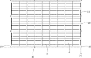
基板2としては、1200mm×802mm×3.2mmのフロート板強化ガラス(白板ガラス)を使用した。基板2は表裏にエンボスが形成された型板ガラスである。基板2の光入射側の面には、小さなエンボスが形成されていて防眩性が付与されている。基板2の太陽電池セル4と向かい合う面には、それより大きなエンボスが形成されており、封止に際して減圧した際に内部の空気が排出されやすくなっている。当該強化ガラスの表面圧縮応力は100MPaである。本実施例において、封止樹脂シートとしては、三井化学ファブロ株式会社製「ソーラーエバSC36」の厚さ0.6mmのものを切断して使用した。当該封止樹脂シートは、エチレン−酢酸ビニル共重合体(EVA)に架橋剤、シランカップリング剤、安定剤などを配合したものであり、架橋前の樹脂のDSC法で測定した融点は71℃である。封止樹脂シートの片面には浅いエンボス模様(梨地)が形成されていて、その深さは約45μmである。基板2の上に、1200mm×802mmの寸法の第1封止樹脂シート20を1枚重ねた。   As the substrate 2, a float plate tempered glass (white plate glass) having a size of 1200 mm × 802 mm × 3.2 mm was used. The substrate 2 is a template glass having embosses formed on the front and back sides. A small emboss is formed on the light incident side surface of the substrate 2 to provide antiglare properties. A larger emboss is formed on the surface of the substrate 2 facing the solar battery cell 4 so that the internal air is easily discharged when the pressure is reduced during sealing. The surface compressive stress of the tempered glass is 100 MPa. In this example, as the sealing resin sheet, “Solar Eva SC36” manufactured by Mitsui Chemicals Fabro Co., Ltd. having a thickness of 0.6 mm was cut and used. The sealing resin sheet is obtained by blending an ethylene-vinyl acetate copolymer (EVA) with a crosslinking agent, a silane coupling agent, a stabilizer and the like, and the melting point measured by the DSC method of the resin before crosslinking is 71 ° C. It is. A shallow embossed pattern (pear texture) is formed on one side of the sealing resin sheet, and the depth is about 45 μm. One first sealing resin sheet 20 having a size of 1200 mm × 802 mm was stacked on the substrate 2.

前述の要領で相互に接続した複数の太陽電池セル4を、第1封止樹脂シート20の上に載置して、縦横を揃えて図7に示すように配列した。引き続き、左右の余白部10において、導線8を導線51で接続した。導線51に対しては外部への引き出し線(図示を省略)が接続される。隣接する太陽電池セル4間の間隙部9の幅は、縦横ともに2mmとした。また、太陽電池セル4の外側の余白部10の幅は、長手方向(9枚のセルが並んでいる方向)で29.5mm、幅方向(6枚のセルが並んでいる方向)で21mmとした。   A plurality of solar cells 4 connected to each other in the manner described above were placed on the first sealing resin sheet 20 and aligned as shown in FIG. Subsequently, the conductor 8 was connected by the conductor 51 in the left and right margins 10. An external lead wire (not shown) is connected to the conductive wire 51. The width of the gap 9 between the adjacent solar cells 4 was set to 2 mm both vertically and horizontally. Further, the width of the outer margin 10 of the solar battery cell 4 is 29.5 mm in the longitudinal direction (the direction in which nine cells are arranged) and 21 mm in the width direction (the direction in which six cells are arranged). did.

続いて、図7に示すように、余白部10において、第1封止樹脂シート20の上に封止樹脂シート片40を12枚配置した。封止樹脂シート片40の寸法は、5×10×0.6mmである。余白部10の封止樹脂シート片40を間欠的に配置することによって、内部の空気を排出する際の通路が確保できて、気泡残りを防止することができる。封止樹脂シート片40を配置してから、その上に1200mm×802mmの寸法の第2封止樹脂シート30を重ねた。   Subsequently, as shown in FIG. 7, twelve sealing resin sheet pieces 40 were arranged on the first sealing resin sheet 20 in the blank portion 10. The dimension of the sealing resin sheet piece 40 is 5 × 10 × 0.6 mm. By disposing the sealing resin sheet pieces 40 of the blank portion 10 intermittently, a passage for discharging the internal air can be secured, and bubbles can be prevented from remaining. After disposing the sealing resin sheet piece 40, the second sealing resin sheet 30 having a size of 1200 mm × 802 mm was stacked thereon.

当て板11として、基板2で使用したのと同じフロート板強化ガラスを使用した。フィルム3として、厚さが50μmのポリフッ化ビニリデンフィルム(デュポン社製「テドラーTST20BG4」)を、当て板11よりも少し大きい寸法に切り出したものを使用した。当て板11の片面をフィルム3で覆い、その端部12を折り返し、耐熱粘着テープ13を用いて当て板11の裏側で固定した。そしてフィルム3が下になるようにして第2封止樹脂シート30の上に重ねた。   As the backing plate 11, the same float plate tempered glass as used in the substrate 2 was used. As the film 3, a polyvinylidene fluoride film having a thickness of 50 μm (“Tedlar TST20BG4” manufactured by DuPont) cut into a size slightly larger than the backing plate 11 was used. One side of the backing plate 11 was covered with the film 3, its end 12 was folded back, and fixed on the back side of the backing plate 11 using a heat-resistant adhesive tape 13. And it piled up on the 2nd sealing resin sheet 30 so that the film 3 might become down.

こうして得られた積層体60を用い、図6に示す封止処理装置を用いて封止操作を行った。まず、積層体60の外縁の全周をブリーダー62で覆い、封止処理容器61であるゴム製の袋の中に投入し、パイプ64と接続してオーブン63に入れた。   Sealing operation was performed using the laminated body 60 obtained in this way, using the sealing processing apparatus shown in FIG. First, the entire periphery of the outer edge of the laminate 60 was covered with a bleeder 62, put into a rubber bag as a sealing processing container 61, connected to a pipe 64, and put into an oven 63.

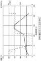
以上のようにセッティングしてから、以下の工程1〜6の封止処理操作を行った。このときの温度と圧力は、表1及び図8に示すとおりに制御した。このときの温度はオーブン63内の温度であり、圧力は圧力計74で測定された圧力である。   After setting as described above, the sealing processing operations of the following steps 1 to 6 were performed. The temperature and pressure at this time were controlled as shown in Table 1 and FIG. The temperature at this time is the temperature in the oven 63, and the pressure is the pressure measured by the pressure gauge 74.

工程1:「封止処理容器内の圧力を0.05MPa以上に保って封止樹脂を加熱する工程」
大気圧(0.1MPa)に保ったままで、室温(30℃)から昇温を開始し、25分かけて53℃まで昇温した。次いで、5分かけて53℃から57℃まで昇温するとともに大気圧から0.08MPaまで減圧した。次いで、57℃に保ったままで、10分かけて0.08MPaから0.05MPaまで減圧した。
Step 1: “Step of heating the sealing resin while maintaining the pressure in the sealing treatment container at 0.05 MPa or more”
While maintaining the atmospheric pressure (0.1 MPa), the temperature increase was started from room temperature (30 ° C.), and the temperature was increased to 53 ° C. over 25 minutes. Next, the temperature was raised from 53 ° C. to 57 ° C. over 5 minutes and the pressure was reduced from atmospheric pressure to 0.08 MPa. Next, while maintaining the temperature at 57 ° C., the pressure was reduced from 0.08 MPa to 0.05 MPa over 10 minutes.

工程2:「封止樹脂の融点未満の温度において封止処理容器内を減圧する工程」
13分かけて57℃から60℃まで昇温するとともに0.05MPaから0.005MPa未満まで減圧した。
Step 2: “Depressurizing the inside of the sealing treatment container at a temperature below the melting point of the sealing resin”
The temperature was raised from 57 ° C. to 60 ° C. over 13 minutes and the pressure was reduced from 0.05 MPa to less than 0.005 MPa.

工程3:「減圧したままで封止樹脂の融点以上の温度まで昇温する工程」
47分かけて60℃から71℃まで昇温し、71℃で5分間維持し、3分かけて71℃から80℃まで昇温した。この間、圧力は0.005MPa未満に維持した。
Step 3: “Step of raising the temperature to a temperature equal to or higher than the melting point of the sealing resin with reduced pressure”
The temperature was raised from 60 ° C. to 71 ° C. over 47 minutes, maintained at 71 ° C. for 5 minutes, and raised from 71 ° C. to 80 ° C. over 3 minutes. During this time, the pressure was maintained below 0.005 MPa.

工程4:「前記封止処理容器内の圧力を上昇させる工程」
2分かけて80℃から85℃まで昇温し、それと同時に、0.005MPa未満であった圧力を0.07MPaまで昇圧した。このときの昇温速度(℃/分)に対する昇圧速度(MPa/分)の比は、0.014(MPa/℃)であった。
Step 4: “Step of increasing the pressure in the sealing treatment container”
The temperature was raised from 80 ° C. to 85 ° C. over 2 minutes, and at the same time, the pressure that was less than 0.005 MPa was increased to 0.07 MPa. The ratio of the pressure increase rate (MPa / min) to the temperature increase rate (° C./min) at this time was 0.014 (MPa / ° C.).

工程5:「架橋反応が進行する温度範囲まで昇温して架橋反応を進行させる工程」
25分かけて85℃から155℃まで昇温し、155℃で17分間維持して架橋反応を進行させた。この間0.07MPaの圧力を維持した。
Step 5: “Step of raising the temperature to a temperature range where the crosslinking reaction proceeds to advance the crosslinking reaction”
The temperature was raised from 85 ° C. to 155 ° C. over 25 minutes and maintained at 155 ° C. for 17 minutes to allow the crosslinking reaction to proceed. During this time, the pressure of 0.07 MPa was maintained.

工程6:「冷却する工程」
0.07MPaの圧力を維持しながら60分かけて155℃から30℃まで冷却した。30℃になったところで約1分かけて0.07MPaから0.1MPa(大気圧)まで昇圧して、オーブン63から取り出した。
Process 6: “Cooling process”
While maintaining a pressure of 0.07 MPa, cooling was performed from 155 ° C. to 30 ° C. over 60 minutes. When the temperature reached 30 ° C., the pressure was increased from 0.07 MPa to 0.1 MPa (atmospheric pressure) over about 1 minute, and the product was taken out from the oven 63.

Figure 0004682014
Figure 0004682014

積層体60をオーブン63に投入する前にはフィルム3には部分的に僅かなたるみが認められていたが、封止処理を終えてオーブン63から取り出したところ、フィルム3は全体がピンと張られていた。このことから、フィルム3の縁部12を固定することによって、封止処理中にフィルム3が収縮しようとするのを効果的に防止することができ、フィルム3が収縮しようとする張力がかかった状態で封止操作が行われたことがわかる。引き続き、耐熱粘着テープ13を剥離して当て板11を外し、余分なフィルム3を切り落とした。得られた太陽電池モジュール1は、セルの割れや欠け、導線の断線は一切なく、気泡残りも観察されず、周辺部での封止樹脂のはみ出しやヒケもほとんど観察されなかった。また、太陽電池セル4は、規則正しく配列されていて、フィルム3の表面は極めて平滑であった。   Before the laminated body 60 was put into the oven 63, a slight slack was partially observed in the film 3. However, when the sealing process was finished and the film 3 was taken out from the oven 63, the film 3 was stretched as a whole. It was. From this, it was possible to effectively prevent the film 3 from contracting during the sealing process by fixing the edge 12 of the film 3, and the film 3 was under tension to contract. It can be seen that the sealing operation was performed in the state. Subsequently, the heat-resistant adhesive tape 13 was peeled off, the backing plate 11 was removed, and the excess film 3 was cut off. The obtained solar cell module 1 had no cell cracking or chipping, no disconnection of the conducting wire, no bubble residue was observed, and no protrusion or sink of the sealing resin in the peripheral portion was observed. Moreover, the photovoltaic cells 4 were regularly arranged, and the surface of the film 3 was extremely smooth.

比較例1
実施例1において、フィルム3を当て板11に固定せずに、第2封止樹脂シート30と当て板11の間に挟んだ点以外は実施例1と同様にして太陽電池モジュール1を製造した。その結果、得られた太陽電池モジュール1は、セルの割れや欠け、導線8の断線は一切なく、気泡残りも観察されず、周辺部での封止樹脂のはみ出しやヒケもほとんど観察されなかった。また、太陽電池セル4は、規則正しく配列されていた。しかしながら、フィルム3の表面にはセルや配線に由来する凹凸が転写されていて、一部領域に局所的なシワが発生していた。
Comparative Example 1
In Example 1, the solar cell module 1 was manufactured in the same manner as in Example 1 except that the film 3 was not fixed to the backing plate 11 and was sandwiched between the second sealing resin sheet 30 and the backing plate 11. . As a result, in the obtained solar cell module 1, there was no cell cracking or chipping, no disconnection of the conducting wire 8, no bubble residue was observed, and no protrusion or sinking of the sealing resin in the peripheral part was observed. . Moreover, the photovoltaic cells 4 were regularly arranged. However, irregularities derived from cells and wirings were transferred to the surface of the film 3, and local wrinkles were generated in some areas.

実施例2
太陽電池セル4として、125mm×125mm×0.35mmの正方形の多結晶シリコン太陽電池セルを24枚使用した。四隅は数mm程度面取りがされている。導線8としては、日立電線株式会社製のハンダディップ銅リボン線を使用した。当該リボン線の幅は1.5mmで厚さは約0.1mmである。太陽電池セル4の受光面6と裏面7の導線8を接着する部分には予めハンダを印刷してある。導線8の一端を太陽電池セル4の受光面6のハンダ印刷部に重ねてハンダ付けし、他端を隣接する太陽電池セル4の裏面7のハンダ印刷部に重ねてハンダ付けした。隣接するセル間は2本の導線8で接続し、その間隔が50mmになるようにした。すなわち、間隙部9の幅は50mmである。ハンダ付けに際しては、太陽電池セル4を、受光面6が上になるようにホットプレートに載せて、加熱しながら導線8を受光面6にハンダ付けしてから、ガラス板上で放冷した。これによって、受光面6が凸面側になる向きに湾曲した。その後、裏面7に導線8をハンダごてでハンダ付けしたが、前記湾曲は維持されたままであった。このようにして導線8が接続された太陽電池セル4は、受光面6が凸面側になるように、直列方向と垂直に2〜3mm程度湾曲していた。
Example 2
As the solar battery cell 4, 24 square polycrystalline silicon solar battery cells of 125 mm × 125 mm × 0.35 mm were used. The four corners are chamfered about several mm. As the conducting wire 8, a solder dip copper ribbon wire manufactured by Hitachi Cable, Ltd. was used. The ribbon wire has a width of 1.5 mm and a thickness of about 0.1 mm. Solder is printed in advance on a portion where the light receiving surface 6 of the solar battery cell 4 and the conductive wire 8 on the back surface 7 are bonded. One end of the conductor 8 was overlapped and soldered to the solder printing portion of the light receiving surface 6 of the solar battery cell 4, and the other end was overlapped and soldered to the solder printing portion of the back surface 7 of the adjacent solar battery cell 4. Adjacent cells were connected by two conducting wires 8 so that the distance between them was 50 mm. That is, the width of the gap 9 is 50 mm. In soldering, the solar battery cell 4 was placed on a hot plate with the light receiving surface 6 facing upward, the conductor 8 was soldered to the light receiving surface 6 while heating, and then allowed to cool on the glass plate. As a result, the light receiving surface 6 was bent in a direction toward the convex surface side. Thereafter, the conductor 8 was soldered to the back surface 7 with a soldering iron, but the curvature was maintained. The solar cells 4 to which the conductive wires 8 were connected in this way were bent about 2 to 3 mm perpendicular to the series direction so that the light receiving surface 6 was on the convex side.

基板2としては、1200mm×800mm×5mmの強化曲げガラス(白板ガラス)を使用した。当該強化曲げガラスの形状は、円筒の一部からなるものであり、その短辺が湾曲しているものである。当該湾曲の曲率半径は1000mmであり、短辺の長さ800mmは、曲線としての長さである。また、当該強化曲げガラスの表面圧縮応力は100MPaである。本実施例において、封止樹脂シートとしては、三井化学ファブロ株式会社製「ソーラーエバSC36」の厚さ0.6mmのものを切断して使用した。当該封止樹脂シートは、エチレン−酢酸ビニル共重合体(EVA)に架橋剤、シランカップリング剤、安定剤などを配合したものであり、架橋前の樹脂のDSC法で測定した融点は71℃である。封止樹脂シートの片面には浅いエンボス模様(梨地)が形成されていて、その深さは約45μmである。基板2の凹面が上になるようにして、その上に1200mm×800mmの寸法の封止樹脂シート21,22,23を3枚重ねた。この3枚の封止樹脂シート21,22,23が厚み1.8mmの第1封止樹脂シート20を構成する。   As the substrate 2, tempered bent glass (white plate glass) of 1200 mm × 800 mm × 5 mm was used. The shape of the tempered bent glass consists of a part of a cylinder, and its short side is curved. The curvature radius of the curve is 1000 mm, and the short side length of 800 mm is the length as a curve. The tempered bent glass has a surface compressive stress of 100 MPa. In this example, as the sealing resin sheet, “Solar Eva SC36” manufactured by Mitsui Chemicals Fabro Co., Ltd. having a thickness of 0.6 mm was cut and used. The sealing resin sheet is obtained by blending an ethylene-vinyl acetate copolymer (EVA) with a crosslinking agent, a silane coupling agent, a stabilizer and the like, and the melting point measured by the DSC method of the resin before crosslinking is 71 ° C. It is. A shallow embossed pattern (pear texture) is formed on one side of the sealing resin sheet, and the depth is about 45 μm. Three sealing resin sheets 21, 22, and 23 having a size of 1200 mm × 800 mm were stacked thereon so that the concave surface of the substrate 2 was on top. The three sealing resin sheets 21, 22, and 23 constitute a first sealing resin sheet 20 having a thickness of 1.8 mm.

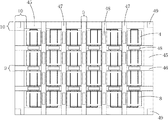
図9に示すように、短辺方向に4枚の太陽電池セル4を直列に接続したものを50mm間隔で平行に6組並べ、合計24枚のセルを、第1封止樹脂シート20の上に配置した。隣接する太陽電池セル4間の間隙部9の幅は、縦横ともに50mmである。太陽電池セル4の端から基板2の端部までの距離、すなわち余白部10の幅は、図9における左右端で100mm、上下端で75mmとした。引き続き、上下の余白部10において、導線8を導線51で接続した。導線51に対しては外部への引き出し線(図示を省略)が接続される。   As shown in FIG. 9, six sets of four solar cells 4 connected in series in the short side direction are arranged in parallel at intervals of 50 mm, and a total of 24 cells are arranged on the first sealing resin sheet 20. Arranged. The width of the gap 9 between the adjacent solar battery cells 4 is 50 mm both vertically and horizontally. The distance from the end of the solar battery cell 4 to the end of the substrate 2, that is, the width of the margin 10, was 100 mm at the left and right ends in FIG. 9 and 75 mm at the upper and lower ends. Subsequently, the conductor 8 was connected by the conductor 51 in the upper and lower margins 10. An external lead wire (not shown) is connected to the conductive wire 51.

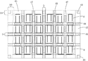
続いて、図10に示すように、余白部10に封止樹脂シート片45を配置する。封止樹脂シート片45は余白部10の全周にわたり、基板2の端部に沿って配置した。左右の余白部10(幅が100mm)では、封止樹脂シート片45の幅は80mmであり、上下の余白部10(幅が75mm)では、封止樹脂シート片45の幅は60mmである。次に、図11に示すように幅45mmで長さ1200mmの封止樹脂シート片46を太陽電池セル4間の間隙部9に3本平行に載置した。封止樹脂シート片46は、両端部において封止樹脂シート片45の上に重なっていて、一部が導線8の上に重なっている。次に、幅45mmで長さ800mmの封止樹脂シート片47を太陽電池セル4間の間隙部9に5本平行に載置した。封止樹脂シート片47は、両端部において封止樹脂シート片45の上に重なっていて、一部が封止樹脂シート片45及び導線の上に重なっている。   Subsequently, as illustrated in FIG. 10, the sealing resin sheet piece 45 is disposed in the blank portion 10. The sealing resin sheet piece 45 was disposed along the edge of the substrate 2 over the entire circumference of the blank portion 10. In the left and right margin portions 10 (width is 100 mm), the width of the sealing resin sheet piece 45 is 80 mm, and in the upper and lower margin portions 10 (width is 75 mm), the width of the sealing resin sheet piece 45 is 60 mm. Next, as shown in FIG. 11, three sealing resin sheet pieces 45 having a width of 45 mm and a length of 1200 mm were placed in parallel in the gap 9 between the solar cells 4. The sealing resin sheet piece 46 overlaps the sealing resin sheet piece 45 at both ends, and a part thereof overlaps the conductive wire 8. Next, five sealing resin sheet pieces 47 having a width of 45 mm and a length of 800 mm were placed in parallel in the gap 9 between the solar cells 4. The sealing resin sheet piece 47 overlaps the sealing resin sheet piece 45 at both ends, and a part thereof overlaps the sealing resin sheet piece 45 and the conductive wire.

引き続き図12に示すように、相互に隣接する太陽電池セル4同士の間隙部9において、封止樹脂シート片46,47の上に40mm×100mmの封止樹脂シート片48を38枚配置した。さらに、モジュールの四隅の封止樹脂シート片45の上に、50mm×50mmの封止樹脂シート片49を4枚配置した。図13において、斜線で示された部分では封止樹脂シート片の厚さが合計で1.2mmであり、その他の部分の封止樹脂シート片の厚さは0.6mmである。このような構成とすることにより、引き続き積層される封止樹脂シート31と封止樹脂シート片45との間に間隙を設けることができ、封止樹脂シート23と封止樹脂シート31の間に形成される空間の空気を円滑に排出することができる。続いて、その上に1200mm×800mmの寸法の封止樹脂シート31,32,33を3枚重ねた。この3枚の封止樹脂シート31,32,33が厚み1.8mmの第2封止樹脂シート30を構成する。   Subsequently, as shown in FIG. 12, 38 sealing resin sheet pieces 48 of 40 mm × 100 mm were arranged on the sealing resin sheet pieces 46 and 47 in the gap 9 between the adjacent solar cells 4. Furthermore, four 50 mm × 50 mm sealing resin sheet pieces 49 were arranged on the sealing resin sheet pieces 45 at the four corners of the module. In FIG. 13, the total thickness of the encapsulating resin sheet piece is 1.2 mm in the portion indicated by hatching, and the thickness of the encapsulating resin sheet piece in the other portion is 0.6 mm. By setting it as such a structure, a clearance gap can be provided between the sealing resin sheet 31 and the sealing resin sheet piece 45 which are laminated | stacked continuously, and between the sealing resin sheet 23 and the sealing resin sheet 31 can be provided. The air in the formed space can be discharged smoothly. Subsequently, three sealing resin sheets 31, 32, and 33 having a size of 1200 mm × 800 mm were stacked thereon. The three sealing resin sheets 31, 32, 33 constitute a second sealing resin sheet 30 having a thickness of 1.8 mm.

当て板11として、基板2で使用したのと同じ強化曲げガラスを使用した。フィルム3として、厚さが50μmのポリフッ化ビニリデンフィルム(デュポン社製「テドラーTST20BG4」)を、当て板11よりも少し大きい寸法に切り出したものを使用した。当て板11の凸面を、表面に沿うようにフィルム3で覆い、その端部12を折り返し、耐熱粘着テープ13を用いて当て板11の裏側で固定した。そしてフィルム3が下になるようにして第2封止樹脂シート30の上に重ねた。   The same tempered bent glass as that used for the substrate 2 was used as the backing plate 11. As the film 3, a polyvinylidene fluoride film having a thickness of 50 μm (“Tedlar TST20BG4” manufactured by DuPont) cut into a size slightly larger than the backing plate 11 was used. The convex surface of the backing plate 11 was covered with the film 3 so as to be along the surface, the end portion 12 was folded back, and fixed on the back side of the backing plate 11 using a heat-resistant adhesive tape 13. And it piled up on the 2nd sealing resin sheet 30 so that the film 3 might become down.

こうして得られた積層体60を用い、図6に示す封止処理装置を用いて封止操作を行った。まず、積層体60の外縁の全周をブリーダー62で覆い、封止処理容器61であるゴム製の袋の中に投入し、パイプ64と接続してオーブン63に入れた。   Sealing operation was performed using the laminated body 60 obtained in this way, using the sealing processing apparatus shown in FIG. First, the entire periphery of the outer edge of the laminate 60 was covered with a bleeder 62, put into a rubber bag as a sealing processing container 61, connected to a pipe 64, and put into an oven 63.

以上のようにセッティングしてから、以下の工程1〜6の封止処理操作を行った。このときの温度と圧力は、表2及び図14に示すとおりに制御した。このときの温度はオーブン63内の温度であり、圧力は圧力計74で測定された圧力である。   After setting as described above, the sealing processing operations of the following steps 1 to 6 were performed. The temperature and pressure at this time were controlled as shown in Table 2 and FIG. The temperature at this time is the temperature in the oven 63, and the pressure is the pressure measured by the pressure gauge 74.

工程1:「封止処理容器内の圧力を0.05MPa以上に保って封止樹脂を加熱する工程」
45分かけて圧力を大気圧(0.1MPa)からゆっくりと0.07MPaまで低下させ、その間、温度を室温(30℃)からゆっくりと50℃まで上昇させた。
Step 1: “Step of heating the sealing resin while maintaining the pressure in the sealing treatment container at 0.05 MPa or more”
The pressure was slowly reduced from atmospheric pressure (0.1 MPa) to 0.07 MPa over 45 minutes, during which time the temperature was slowly increased from room temperature (30 ° C.) to 50 ° C.

工程2:「封止樹脂の融点未満の温度において封止処理容器内を減圧する工程」
30分かけて圧力を0.07MPaから0.005MPa未満まで減圧した。この間、温度を50℃に保った。
Step 2: “Depressurizing the inside of the sealing treatment container at a temperature below the melting point of the sealing resin”
The pressure was reduced from 0.07 MPa to less than 0.005 MPa over 30 minutes. During this time, the temperature was maintained at 50 ° C.

工程3:「減圧したままで封止樹脂の融点以上の温度まで昇温する工程」
50℃から60℃まで120分かけて昇温し、60℃から71℃まで150分かけて昇温し、71℃で10分間維持してから、71℃から78℃まで45分かけて昇温した。この間、封止処理容器内の圧力を0.005MPa未満に維持した。
Step 3: “Step of raising the temperature to a temperature equal to or higher than the melting point of the sealing resin with reduced pressure”
The temperature was raised from 50 ° C. to 60 ° C. over 120 minutes, the temperature was raised from 60 ° C. to 71 ° C. over 150 minutes, maintained at 71 ° C. for 10 minutes, and then heated from 71 ° C. to 78 ° C. over 45 minutes. did. During this time, the pressure in the sealing treatment container was maintained at less than 0.005 MPa.

工程4:「前記封止処理容器内の圧力を上昇させる工程」
前記工程3において、温度が78℃になったところで昇圧を開始し、0.005MPa未満から0.07MPaまで70分かけてゆっくりと昇圧した。この間、温度は78℃から90℃まで75分かけてゆっくりと上昇させた。このときの昇温速度(℃/分)に対する昇圧速度(MPa/分)の比は、0.0063(MPa/℃)であった。この後、90℃で30分間維持し、30分かけて30℃まで冷却し、30℃で5分間維持し、その間0.07MPaの圧力を維持した。
Step 4: “Step of increasing the pressure in the sealing treatment container”
In step 3, when the temperature reached 78 ° C., pressurization was started, and the pressure was slowly increased from less than 0.005 MPa to 0.07 MPa over 70 minutes. During this time, the temperature was slowly increased from 78 ° C. to 90 ° C. over 75 minutes. The ratio of the pressure increase rate (MPa / min) to the temperature increase rate (° C./min) at this time was 0.0063 (MPa / ° C.). Thereafter, the temperature was maintained at 90 ° C. for 30 minutes, cooled to 30 ° C. over 30 minutes, maintained at 30 ° C. for 5 minutes, and a pressure of 0.07 MPa was maintained during that time.

工程5:「架橋反応が進行する温度範囲まで昇温して架橋反応を進行させる工程」
90分かけて30℃から155℃まで昇温し、155℃で36分間維持して架橋反応を進行させた。その間0.07MPaの圧力を維持した。
Step 5: “Step of raising the temperature to a temperature range where the crosslinking reaction proceeds to advance the crosslinking reaction”
The temperature was raised from 30 ° C. to 155 ° C. over 90 minutes and maintained at 155 ° C. for 36 minutes to allow the crosslinking reaction to proceed. Meanwhile, a pressure of 0.07 MPa was maintained.

工程6:「冷却する工程」
60分かけて155℃から30℃まで冷却した。30℃になったところで約1分かけて0.07MPaから0.1MPa(大気圧)まで昇圧して、オーブン63から取り出した。
Process 6: “Cooling process”
Cooled from 155 ° C. to 30 ° C. over 60 minutes. When the temperature reached 30 ° C., the pressure was increased from 0.07 MPa to 0.1 MPa (atmospheric pressure) over about 1 minute, and the product was taken out from the oven 63.

Figure 0004682014
Figure 0004682014

積層体60をオーブン63に投入する前にはフィルム3には部分的に僅かなたるみが認められていたが、封止処理を終えてオーブン63から取り出したところ、フィルム3は全体がピンと張られていた。このことから、フィルム3の縁部12を固定することによって、封止処理中にフィルム3が収縮しようとするのを効果的に防止することができ、フィルム3が収縮しようとする張力がかかった状態で封止操作が行われたことがわかる。引き続き、耐熱粘着テープ13を剥離して当て板11を外し、余分なフィルム3を切り落とした。得られた太陽電池モジュールは、セルの割れや欠け、導線の断線は一切なく、気泡残りも観察されず、周辺部での封止樹脂のはみ出しやヒケもほとんど観察されなかった。また、太陽電池セルは、規則正しく配列されていて、フィルム3の表面は極めて平滑な曲面であった。   Before the laminated body 60 was put into the oven 63, a slight slack was partially observed in the film 3. However, when the sealing process was finished and the film 3 was taken out from the oven 63, the film 3 was stretched as a whole. It was. From this, it was possible to effectively prevent the film 3 from contracting during the sealing process by fixing the edge 12 of the film 3, and the film 3 was under tension to contract. It can be seen that the sealing operation was performed in the state. Subsequently, the heat-resistant adhesive tape 13 was peeled off, the backing plate 11 was removed, and the excess film 3 was cut off. In the obtained solar cell module, there were no cell cracks or chips, no broken wires, no bubble residue was observed, and no protrusion or sink of the sealing resin at the periphery was observed. Moreover, the photovoltaic cells were regularly arranged, and the surface of the film 3 was a very smooth curved surface.

比較例2
実施例2において、フィルム3を当て板11に固定せずに、第2封止樹脂シート30と当て板11の間に挟んだ点以外は実施例2と同様にして太陽電池モジュール1を製造した。その結果、得られた太陽電池モジュール1は、セルの割れや欠け、導線8の断線は一切なく、気泡残りも観察されず、周辺部での封止樹脂のはみ出しやヒケもほとんど観察されなかった。また、太陽電池セル4は、規則正しく配列されていた。しかしながら、フィルム3の表面にはセルや配線に由来する凹凸が転写されていて、一部領域に局所的なシワが発生していた。
Comparative Example 2
In Example 2 , the solar cell module 1 was manufactured in the same manner as in Example 2 except that the film 3 was not fixed to the backing plate 11 and was sandwiched between the second sealing resin sheet 30 and the backing plate 11. . As a result, in the obtained solar cell module 1, there was no cell cracking or chipping, no disconnection of the conducting wire 8, no bubble residue was observed, and no protrusion or sinking of the sealing resin in the peripheral part was observed. . Moreover, the photovoltaic cells 4 were regularly arranged. However, irregularities derived from cells and wirings were transferred to the surface of the film 3, and local wrinkles were generated in some areas.

封止操作後の太陽電池モジュールの一例の断面模式図である。It is a cross-sectional schematic diagram of an example of the solar cell module after sealing operation. 封止操作前の積層体の一例の断面模式図である。It is a cross-sectional schematic diagram of an example of the laminated body before sealing operation. 封止操作前の積層体の他の一例の断面模式図である。It is a cross-sectional schematic diagram of another example of the laminated body before sealing operation. 封止操作前の積層体の他の一例の断面模式図である。It is a cross-sectional schematic diagram of another example of the laminated body before sealing operation. 複数のモジュールを同時に封止する場合の封止操作前の積層体の断面模式図である。It is a cross-sectional schematic diagram of the laminated body before sealing operation in the case of sealing a some module simultaneously. 封止処理装置の一例の模式図である。It is a schematic diagram of an example of a sealing processing apparatus. 実施例1及び比較例1において、第1封止樹脂シート上に太陽電池セルと封止樹脂シート片を載置したところを示す平面模式図である。In Example 1 and Comparative Example 1, it is a plane schematic diagram which shows the place which mounted the photovoltaic cell and the sealing resin sheet piece on the 1st sealing resin sheet. 実施例1及び比較例1における封止処理時の温度と圧力を示した図である。It is the figure which showed the temperature and pressure at the time of the sealing process in Example 1 and Comparative Example 1. FIG. 実施例2及び比較例2における積層工程の手順を示した図(その1)である。It is FIG. (The 1) which showed the procedure of the lamination process in Example 2 and Comparative Example 2. FIG. 実施例2及び比較例2における積層工程の手順を示した図(その2)である。It is the figure (the 2) which showed the procedure of the lamination process in Example 2 and Comparative Example 2. FIG. 実施例2及び比較例2における積層工程の手順を示した図(その3)である。FIG. 6 is a diagram (No. 3) illustrating a procedure of a stacking process in Example 2 and Comparative Example 2. 実施例2及び比較例2における積層工程の手順を示した図(その4)である。It is FIG. (The 4) which showed the procedure of the lamination process in Example 2 and Comparative Example 2. FIG. 実施例2及び比較例2における封止樹脂シート片の厚み分布を示した図である。It is the figure which showed the thickness distribution of the sealing resin sheet piece in Example 2 and Comparative Example 2. 実施例2及び比較例2における封止処理時の温度と圧力を示した図である。It is the figure which showed the temperature and pressure at the time of the sealing process in Example 2 and Comparative Example 2. FIG.

符号の説明Explanation of symbols

1 太陽電池モジュール
2 基板
3 フィルム
4 太陽電池セル
5 樹脂
8 導線
9 間隙部
10 余白部
11 当て板
20 第1封止樹脂シート
30 第2封止樹脂シート
40〜49 封止樹脂シート片
60 積層体
61 封止処理容器
63 オーブン
66 タンク
67 真空ポンプ
DESCRIPTION OF SYMBOLS 1 Solar cell module 2 Board | substrate 3 Film 4 Solar cell 5 Resin 8 Conductor 9 Gap part 10 Blank part 11 Catch plate 20 1st sealing resin sheet 30 2nd sealing resin sheet 40-49 Sealing resin sheet piece 60 Laminate 61 Sealing treatment vessel 63 Oven 66 Tank 67 Vacuum pump

Claims (11)

基板とフィルムとの間に太陽電池セルが樹脂で封止されてなる太陽電池モジュールの製造方法において、前記基板と前記太陽電池セルとの間に前記基板の実質的に全面を覆う第1封止樹脂シートを配置し、前記フィルムと前記太陽電池セルとの間に前記基板の実質的に全面を覆う第2封止樹脂シートを配置し、前記フィルムの縁部を固定するとともに前記フィルムの外側に該フィルムの実質的に全体を覆うことのできる面積の当て板を配置してから、気体不透過性の柔軟なシートからなる封止処理容器内において、前記基板と前記フィルムとの間の空気を排出し、加熱して樹脂を溶融させてから冷却して封止するに際し、前記フィルムとして熱収縮性を有するフィルムを使用し、該フィルムの縁部を固定することによって封止操作中に収縮しないようにすることを特徴とする太陽電池モジュールの製造方法。 In a method for manufacturing a solar cell module in which solar cells are sealed with resin between a substrate and a film, a first seal that covers substantially the entire surface of the substrate between the substrate and the solar cells. A resin sheet is disposed, a second sealing resin sheet covering substantially the entire surface of the substrate is disposed between the film and the solar battery cell, the edge of the film is fixed, and the outside of the film air between from when placing the caul plates of the area capable of substantially covering the whole of the film, the sealing processing chamber composed of gas-impermeable flexible sheet, the substrate and the film discharges, when heated to melt the resin for sealing then cooled, using a film having a heat-shrinkable as the film, shrinkage during sealing operation by fixing the edges of the film Method of manufacturing a solar cell module, which comprises as the no. 前記基板の厚みが2〜25mmであり、フィルムの厚みが0.01〜0.3mmである請求項1記載の太陽電池モジュールの製造方法。   The method for producing a solar cell module according to claim 1, wherein the thickness of the substrate is 2 to 25 mm, and the thickness of the film is 0.01 to 0.3 mm. 前記基板が湾曲していて、前記当て板が前記基板と実質的に同じ曲率で湾曲している請求項1又は2記載の太陽電池モジュールの製造方法。   The method for manufacturing a solar cell module according to claim 1, wherein the substrate is curved, and the contact plate is curved with substantially the same curvature as the substrate. 前記封止樹脂が、エチレン−酢酸ビニル共重合体、ポリビニルブチラール及びポリウレタンからなる群から選択される一種の樹脂である請求項1〜のいずれか記載の太陽電池モジュールの製造方法。 The method for producing a solar cell module according to any one of claims 1 to 3 , wherein the sealing resin is a kind of resin selected from the group consisting of ethylene-vinyl acetate copolymer, polyvinyl butyral, and polyurethane. 複数の太陽電池セルを間隔をあけて配列して相互に導線で接続して封止する請求項1〜のいずれか記載の太陽電池モジュールの製造方法。 The process according to claim 1-4 solar cell module according to any one of the sealing connected by wires to one another a plurality of solar cells are arranged at intervals. 太陽電池セル間の間隙部又は太陽電池セルの外側の余白部に、太陽電池セルの厚みよりも厚い封止樹脂シート片を配置する請求項1〜のいずれか記載の太陽電池モジュールの製造方法。 The method for producing a solar cell module according to any one of claims 1 to 5 , wherein a sealing resin sheet piece thicker than the thickness of the solar battery cell is disposed in a gap between the solar battery cells or a blank part outside the solar battery cell. . 前記封止樹脂シート片相互の間に間隔をあけて配置し、そこから内部の空気を排出する請求項記載の太陽電池モジュールの製造方法。 The manufacturing method of the solar cell module of Claim 6 which arrange | positions at intervals between the said sealing resin sheet pieces, and discharges internal air from there. 前記フィルムの縁部を前記当て板、前記基板又は枠体に固定する請求項1〜のいずれか記載の太陽電池モジュールの製造方法。 The edges of the film, said backing plate, a method for manufacturing a solar cell module according to claim 1 to 7 for fixing to the substrate or frame. 複数の前記封止処理容器をオーブン内に導入して相互に間隔をあけて平行に配置し、前記オーブン内において前記基板と平行の向きに熱風を流すことによって加熱して封止樹脂を溶融させる請求項1〜8のいずれか記載の太陽電池モジュールの製造方法。 A plurality of the sealing treatment containers are introduced into the oven and arranged parallel to each other with a space therebetween, and the sealing resin is melted by heating by flowing hot air in a direction parallel to the substrate in the oven. The manufacturing method of the solar cell module in any one of Claims 1-8 . 前記封止処理容器内で封止するに際して、封止樹脂の融点未満の温度において封止処理容器内を減圧する工程(工程2)、減圧したままで封止樹脂の融点以上の温度まで昇温する工程(工程3)、前記封止処理容器内の圧力を上昇させる工程(工程4)、及び冷却する工程(工程6)の各工程からなる封止操作を行う請求項1〜9のいずれか記載の太陽電池モジュールの製造方法。 When sealing in the sealing treatment container, a step of depressurizing the inside of the sealing treatment container at a temperature lower than the melting point of the sealing resin (Step 2); Any one of Claims 1-9 which perform sealing operation which consists of each process of the process to perform (process 3), the process to raise the pressure in the said sealing process container (process 4), and the process to cool (process 6) . The manufacturing method of the solar cell module of description. 前記工程2において封止樹脂の融点未満の温度において封止処理容器内を0.01MPa以下の圧力まで減圧するとともに、該工程2に先立って、封止処理容器内の圧力を0.05MPa以上に保って封止樹脂を加熱する工程(工程1)を有する請求項10記載の太陽電池モジュールの製造方法。
In the step 2, the inside of the sealing treatment container is reduced to a pressure of 0.01 MPa or less at a temperature lower than the melting point of the sealing resin, and prior to the step 2, the pressure in the sealing treatment container is set to 0.05 MPa or more. The manufacturing method of the solar cell module of Claim 10 which has the process (process 1) which maintains and heats sealing resin.
JP2005312032A 2005-10-26 2005-10-26 Manufacturing method of solar cell module Expired - Fee Related JP4682014B2 (en)

Priority Applications (1)

Application Number Priority Date Filing Date Title
JP2005312032A JP4682014B2 (en) 2005-10-26 2005-10-26 Manufacturing method of solar cell module

Applications Claiming Priority (1)

Application Number Priority Date Filing Date Title
JP2005312032A JP4682014B2 (en) 2005-10-26 2005-10-26 Manufacturing method of solar cell module

Publications (3)

Publication Number Publication Date
JP2007123451A JP2007123451A (en) 2007-05-17
JP2007123451A5 JP2007123451A5 (en) 2008-10-30
JP4682014B2 true JP4682014B2 (en) 2011-05-11

Family

ID=38146987

Family Applications (1)

Application Number Title Priority Date Filing Date
JP2005312032A Expired - Fee Related JP4682014B2 (en) 2005-10-26 2005-10-26 Manufacturing method of solar cell module

Country Status (1)

Country Link
JP (1) JP4682014B2 (en)

Families Citing this family (9)

* Cited by examiner, † Cited by third party
Publication number Priority date Publication date Assignee Title
US20100065105A1 (en) * 2008-09-12 2010-03-18 Francois Andre Koran Thin Film Photovoltaic Module Having a Contoured Substrate
JP2010238714A (en) * 2009-03-30 2010-10-21 Lintec Corp Protection sheet for solar cell module, solar cell module and method of manufacturing solar cell module
JP5385666B2 (en) * 2009-04-08 2014-01-08 株式会社ブリヂストン Manufacturing method of solar cell module
JP2010245375A (en) * 2009-04-08 2010-10-28 Bridgestone Corp Method of manufacturing solar cell module
DE112014004416T5 (en) 2013-09-25 2016-07-28 Panasonic Intellectual Property Management Co., Ltd. Solar cell module manufacturing process
CN105810768B (en) * 2016-04-14 2017-11-21 珠海格力电器股份有限公司 Double-glass assembly
CN107394005A (en) * 2017-07-07 2017-11-24 东方环晟光伏(江苏)有限公司 Reduce the method and laminar structure of solar double-glass assemblies air bubble problem
CN111261741A (en) * 2020-01-23 2020-06-09 成都晔凡科技有限公司 Method for manufacturing laminated assembly and laminated assembly
JP7231600B2 (en) * 2020-11-17 2023-03-01 プライムプラネットエナジー&ソリューションズ株式会社 Electrode plate manufacturing method

Citations (5)

* Cited by examiner, † Cited by third party
Publication number Priority date Publication date Assignee Title
JP2001313404A (en) * 2000-04-28 2001-11-09 Mitsubishi Electric Corp Method of manufacturing solar battery module
JP2002118276A (en) * 2000-10-06 2002-04-19 Sharp Corp Solar battery module and its manufacturing method
WO2004038811A1 (en) * 2002-10-25 2004-05-06 Nakajima Glass Co., Inc. Solar battery module manufacturing method
JP2004179261A (en) * 2002-11-25 2004-06-24 Kyocera Corp Device and method for manufacturing solar battery module
WO2005106969A1 (en) * 2004-04-28 2005-11-10 Nakajima Glass Co., Inc. Solar cell module manufacturing method and solar cell module

Family Cites Families (4)

* Cited by examiner, † Cited by third party
Publication number Priority date Publication date Assignee Title
JPS58155776A (en) * 1982-03-11 1983-09-16 Sharp Corp Enclosing system of solar cell
JP3167907B2 (en) * 1995-12-26 2001-05-21 シャープ株式会社 Method and apparatus for bonding solar cell and cover glass
JP3676074B2 (en) * 1997-03-14 2005-07-27 Tdk株式会社 Hot melt material and laminate and method for producing the same
JP3448198B2 (en) * 1997-12-25 2003-09-16 シャープ株式会社 Method of manufacturing solar cell module

Patent Citations (5)

* Cited by examiner, † Cited by third party
Publication number Priority date Publication date Assignee Title
JP2001313404A (en) * 2000-04-28 2001-11-09 Mitsubishi Electric Corp Method of manufacturing solar battery module
JP2002118276A (en) * 2000-10-06 2002-04-19 Sharp Corp Solar battery module and its manufacturing method
WO2004038811A1 (en) * 2002-10-25 2004-05-06 Nakajima Glass Co., Inc. Solar battery module manufacturing method
JP2004179261A (en) * 2002-11-25 2004-06-24 Kyocera Corp Device and method for manufacturing solar battery module
WO2005106969A1 (en) * 2004-04-28 2005-11-10 Nakajima Glass Co., Inc. Solar cell module manufacturing method and solar cell module

Also Published As

Publication number Publication date
JP2007123451A (en) 2007-05-17

Similar Documents

Publication Publication Date Title
JP5209229B2 (en) Manufacturing method of solar cell module
JP4359308B2 (en) Manufacturing method of solar cell module
JP4682014B2 (en) Manufacturing method of solar cell module
JP3875708B2 (en) Manufacturing method of solar cell module
JP4682237B2 (en) Manufacturing method of solar cell module
US8877540B2 (en) Solar cell module and manufacturing method of solar cell module
US11616154B2 (en) Planarization of photovoltaics
JP4969830B2 (en) Manufacturing method of light emitting element module
JP2005072567A (en) Manufacturing method of solar cell module
JP2002039631A (en) Photothermal hybrid panel, hybrid panel main body using it, and method of manufacturing it
JP5470341B2 (en) Manufacturing method of solar cell module
JP2005317714A (en) Solar cell module and its manufacturing method
JP2005317665A (en) Method of manufacturing solar cell module
JP3875715B2 (en) Manufacturing method of solar cell module
JP2005159181A (en) Method of manufacturing solar cell module
CN113437171A (en) Photovoltaic tile easy to install and preparation method thereof
JP2005044911A (en) Solar cell module and its manufacturing process
JP2005044945A (en) Solar cell module and its manufacturing process
CN118630084A (en) Preparation method of photovoltaic module
CN117012849A (en) Manufacturing method of free-form surface efficient solar cell photovoltaic module

Legal Events

Date Code Title Description
A521 Request for written amendment filed

Free format text: JAPANESE INTERMEDIATE CODE: A523

Effective date: 20080527

A521 Request for written amendment filed

Free format text: JAPANESE INTERMEDIATE CODE: A523

Effective date: 20080910

A621 Written request for application examination

Free format text: JAPANESE INTERMEDIATE CODE: A621

Effective date: 20080910

A131 Notification of reasons for refusal

Free format text: JAPANESE INTERMEDIATE CODE: A131

Effective date: 20100727

A977 Report on retrieval

Free format text: JAPANESE INTERMEDIATE CODE: A971007

Effective date: 20100727

A521 Request for written amendment filed

Free format text: JAPANESE INTERMEDIATE CODE: A523

Effective date: 20100927

TRDD Decision of grant or rejection written
A01 Written decision to grant a patent or to grant a registration (utility model)

Free format text: JAPANESE INTERMEDIATE CODE: A01

Effective date: 20110118

A01 Written decision to grant a patent or to grant a registration (utility model)

Free format text: JAPANESE INTERMEDIATE CODE: A01

A61 First payment of annual fees (during grant procedure)

Free format text: JAPANESE INTERMEDIATE CODE: A61

Effective date: 20110207

R150 Certificate of patent or registration of utility model

Free format text: JAPANESE INTERMEDIATE CODE: R150

FPAY Renewal fee payment (event date is renewal date of database)

Free format text: PAYMENT UNTIL: 20140210

Year of fee payment: 3

R250 Receipt of annual fees

Free format text: JAPANESE INTERMEDIATE CODE: R250

R250 Receipt of annual fees

Free format text: JAPANESE INTERMEDIATE CODE: R250

R250 Receipt of annual fees

Free format text: JAPANESE INTERMEDIATE CODE: R250

LAPS Cancellation because of no payment of annual fees