EP2014371B1 - Hache - Google Patents
Hache Download PDFInfo
- Publication number
- EP2014371B1 EP2014371B1 EP20070013650 EP07013650A EP2014371B1 EP 2014371 B1 EP2014371 B1 EP 2014371B1 EP 20070013650 EP20070013650 EP 20070013650 EP 07013650 A EP07013650 A EP 07013650A EP 2014371 B1 EP2014371 B1 EP 2014371B1
- Authority
- EP
- European Patent Office
- Prior art keywords
- operating position
- shredder
- feed pipe
- rotation
- feed tube
- Prior art date
- Legal status (The legal status is an assumption and is not a legal conclusion. Google has not performed a legal analysis and makes no representation as to the accuracy of the status listed.)
- Active
Links
- 238000005520 cutting process Methods 0.000 claims description 20
- 239000000463 material Substances 0.000 claims description 15
- 230000001154 acute effect Effects 0.000 description 2
- 230000005540 biological transmission Effects 0.000 description 1
- 238000004140 cleaning Methods 0.000 description 1
- 230000008878 coupling Effects 0.000 description 1
- 238000010168 coupling process Methods 0.000 description 1
- 238000005859 coupling reaction Methods 0.000 description 1
- 238000001514 detection method Methods 0.000 description 1
- 230000013011 mating Effects 0.000 description 1
- 230000002028 premature Effects 0.000 description 1
- 230000000284 resting effect Effects 0.000 description 1
- 239000002689 soil Substances 0.000 description 1
Images

Classifications
-
- B—PERFORMING OPERATIONS; TRANSPORTING
- B02—CRUSHING, PULVERISING, OR DISINTEGRATING; PREPARATORY TREATMENT OF GRAIN FOR MILLING
- B02C—CRUSHING, PULVERISING, OR DISINTEGRATING IN GENERAL; MILLING GRAIN
- B02C18/00—Disintegrating by knives or other cutting or tearing members which chop material into fragments
- B02C18/06—Disintegrating by knives or other cutting or tearing members which chop material into fragments with rotating knives
- B02C18/08—Disintegrating by knives or other cutting or tearing members which chop material into fragments with rotating knives within vertical containers
- B02C18/12—Disintegrating by knives or other cutting or tearing members which chop material into fragments with rotating knives within vertical containers with drive arranged below container
-
- B—PERFORMING OPERATIONS; TRANSPORTING
- B02—CRUSHING, PULVERISING, OR DISINTEGRATING; PREPARATORY TREATMENT OF GRAIN FOR MILLING
- B02C—CRUSHING, PULVERISING, OR DISINTEGRATING IN GENERAL; MILLING GRAIN
- B02C18/00—Disintegrating by knives or other cutting or tearing members which chop material into fragments
- B02C18/06—Disintegrating by knives or other cutting or tearing members which chop material into fragments with rotating knives
- B02C18/16—Details
- B02C18/22—Feed or discharge means
- B02C18/2225—Feed means
- B02C18/2291—Feed chute arrangements
-
- B—PERFORMING OPERATIONS; TRANSPORTING
- B02—CRUSHING, PULVERISING, OR DISINTEGRATING; PREPARATORY TREATMENT OF GRAIN FOR MILLING
- B02C—CRUSHING, PULVERISING, OR DISINTEGRATING IN GENERAL; MILLING GRAIN
- B02C2201/00—Codes relating to disintegrating devices adapted for specific materials
- B02C2201/06—Codes relating to disintegrating devices adapted for specific materials for garbage, waste or sewage
- B02C2201/066—Codes relating to disintegrating devices adapted for specific materials for garbage, waste or sewage for garden waste
Definitions
- the invention relates to a shredder specified in the preamble of claim 1 genus.
- a shredder which has as a shredding unit a rotary driven knife disc.
- the shredder has a vertical feed channel for shredded material as well as an inclined Astzu Switzerlandkanal on to be cut branches.
- a shredder which has a hopper for shredding and a feed tube for Schnitzelgut.
- the hopper for shredded material is pivotable about the axis of rotation of the shredder.
- the chopping blades and the slicing knives are arranged in chambers which are spatially separate from each other. As a result, shredded material can only be introduced via the hopper for shredding and Schnitzelgut only on the feed tube for Schnitzelgut.
- the invention has for its object to provide a shredder of the generic type, which is simple and easy to use.
- a single feed tube can be placed in several operating positions for different operating modes of the chopper.
- different materials can be supplied to the feeding angle which is advantageous in each case for these materials with a single feed tube, that is, a single feed nozzle. Disruption of the operator by another feed pipe is not given.
- the first mode of operation of the chopping operation is advantageous, wherein the longitudinal center axis of the feed tube in the first operating position relative to the axis of rotation of the comminution unit is in particular approximately parallel.
- an angle between the longitudinal central axis and the axis of rotation is considered to be less than 5 °.
- the angle between the longitudinal central axis and the axis of rotation is about 0 °. In this orientation of the feed tube, the shreds fall approximately perpendicular to the cutter disk. This achieves a good chopping result.
- the second mode of operation is the Schnitzel Anlagen, wherein the longitudinal central axis of the feed tube is inclined in the second operating position relative to the axis of rotation of the cutter disc by an angle of 20 ° to 70 °.
- the longitudinal center axis of the feed tube encloses an angle of 30 ° to 60 ° with the axis of rotation of the comminution unit, in particular a cutter disc. This achieves a good schnitzel result.
- the knives of the shredding unit provided for the shredding of branches come into contact with the material to be chopped and with possibly added soil or the like in the shredding operation, the knives can quickly become dull.
- the direction of rotation of the comminution unit can be switched between a first direction of rotation and a second direction of rotation, wherein each direction of rotation is assigned to an operating mode of the chopper.
- the knives for shredding operation or the knives for shredding are arranged on the shredding unit, in particular a knife disc so that they come in each case only in one direction of rotation in engagement with good to be shredded. As a result, premature dulling of the blades for the Schnitzel réelle is avoided.
- the direction of rotation of the crushing unit in particular the cutter disk can be switched by the operator.
- the direction of rotation of the crushing unit is controlled in dependence on the operating position of the feed tube.
- the direction of rotation is set for the assigned operating mode of the chopper.
- the operator only needs to change the position of the feed tube.
- the direction of rotation of the shredding unit is automatically switched accordingly, so that a separate switching of the direction of rotation by the operator is eliminated.
- the shredder has a mode indicator indicating the operating mode of the chopper depending on the operating position of the feed tube. Based on the displayed operating mode, the operator can set the direction of rotation of the drive motor. Due to the operating mode display, the operator knows which type of material to be cut is to be supplied in this position of the feed pipe. It can be provided that, depending on the position of the feed tube both the direction of rotation of the drive motor controlled and the operating mode of the chopper is displayed.
- the chopper For switching the direction of rotation of the drive motor and / or for controlling the mode indicator is provided; in that the chopper has at least one switch which is actuated in an operating position of the feed pipe and is not actuated in the other operating position of the feed pipe. In this case, a separate switch can also be provided for each operating position of the feed tube.
- the chopper Has at least one stop for determining an operating position of the feed tube.
- the feed tube is pivotable about an approximately perpendicular to the axis of rotation of the crushing unit pivot axis between the operating positions.
- the feed tube between the operating positions is rotatable about an axis of rotation which is inclined relative to the axis of rotation of the comminution unit by an angle.
- the feed tube is rotatably mounted on a pipe socket on the housing of the chopper, wherein the feed tube is mounted on the pipe socket in a connection plane which is inclined relative to the axis of rotation of the shredding unit.
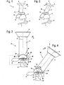
- the in Fig. 1 shown chopper 1 has a housing 2, on which a feed tube 3 is arranged.
- the feed tube 3 has a hopper 4 for filling to be comminuted Good.
- the material to be comminuted passes through the feed tube 3 in the area of a Fig. 1 not shown cutting disc, which comminutes the good. Instead of a knife disc and another shredding device may be advantageous.
- the housing 2 has an ejection 6, over which the comminuted material is ejected from the chopper 1.
- a base 7 is fixed.
- the chopper 1 also has at least one wheel 8 on the base 7, so that the chopper 1 can be easily transported.
- Fig. 1 the chopper 1 is shown in a first operating position 17 of the feed tube 3, in which the longitudinal center axis 5 of the feed tube 3 is approximately perpendicular to the plane of the arranged in the housing 2 cutter disc.
- this operating position 17 can be fed to be chopped Good that falls over the feed tube 3 approximately perpendicular to the cutter disk.
- the feed tube 3 is pivotally mounted about a pivot axis 15. The pivot axis 15 is perpendicular to the longitudinal center axis 5 of the feed tube 3.
- FIGS. 3 and 4 show the chopper 1 in an enlarged and fragmentary representation.
- the chopper 1 has a drive motor 9 which is mounted in the housing 2.
- the drive motor 9 drives a drive shaft 11 about an axis of rotation 12 to rotate.
- a cutter disk 10 is fixed against rotation, which is thus also driven to rotate about the rotation axis 12.
- the feed tube 3 is mounted with its foot 28 on a bearing 16 of the housing 2 about the pivot axis 15 pivotally.
- the foot 28 of the feed tube 3 has for this purpose a part-circular contour, which slides on a corresponding mating contour of the bearing 16.
- Fig. 3 the supply pipe 3 is shown in a first operating position 17, in which the longitudinal center axis 5 of the feed pipe 3 is approximately parallel to the axis of rotation 12 of the cutter disk 10.
- This operating position 17 is provided for chopping operation.
- the angle between the longitudinal center axis 5 of the feed tube 3 and the axis of rotation 12 of the cutter disc 10 is advantageously less than 10 ° and in particular less than 5 °. Particularly advantageous is an angle of 0 ° is considered, in which the longitudinal central axis 5 is parallel to the axis of rotation 12.
- a first stop 19 is provided, against which the feed tube 3 rests in the first operating position 17.
- the stopper 19 thus determines the first operating position 17.
- a second stop 20 is provided, on which the feed tube 3 in the in Fig. 4 shown second operating position 18 is present.
- the housing 2 also has a switch 21, which is actuated in the second operating position 18 of the feed tube 3. As Fig. 3 shows, the switch 21 is not actuated in the first operating position 17.
- the switch 21 is connected to the drive motor 9 and switches the direction of rotation of the drive motor 9. In the in Fig. 3 shown first operating position 17 drives the drive motor 9, the cutter disk 10 in a first direction of rotation 26 on.
- the direction of rotation 26 is provided for the chopping operation of the cutter disk 10.
- a second switch 21 ' may be provided which is actuated in the first operating position 17 and is not actuated in the second operating position 18.
- the drive motor 9 drives the cutter disk 10 in the first direction of rotation 26 when the switch 21 is not actuated.
- the operator can move the feed tube 3 in the direction of the in Fig. 3 shown arrow 22 from the first operating position 17 for Humbleburgteil in the second operating position 18 for Schnitzel réelle.
- the longitudinal center axis 5 of the feed tube 3 is inclined with respect to the plane of the cutter disk 10.
- the longitudinal center axis 5 encloses with the axis of rotation 12 of the cutter disk 10 at an angle ⁇ , which is formed as an acute angle.
- the angle ⁇ is advantageously from 10 ° to 80 °, in particular from 20 ° to 70 ° and preferably from 30 ° to 60 °.
- the switch 21 is actuated.
- the switch 21 switches the drive motor 9 so that the cutter disk 10 is driven in a second direction of rotation 27. This direction of rotation 27 is provided for Schnitzel compassion.
- Fig. 5 the cutter disk 10 is shown schematically in plan view.
- the knife disk 10 has two oppositely disposed cutting blades 13, which lie approximately in the plane of the cutter disk 10. In the direction of rotation 27, the cutting blades 13 come to be comminuted with good. Relative to the second direction of rotation 27 for chips, an opening 24 in the cutter disk 10 is arranged in advance of each cutting blade 13, through which chips can pass into the area below the cutter disk 10.
- the cutting blades 13 are arranged on the outer edge of the cutter disk 10.
- two rupture knives 14 are provided, which are connected to one another via a connecting portion 25 resting against the knife disk 10.
- the two tear knives 14 are arranged so that they engage in a first direction of rotation 26.
- the rupture knives 14 are not active. Due to the fact that the cutting edges of the cutting knives 13 and / or the cutting knives 14 do not engage in cutting in one direction of rotation, excessive wear of the cutting knives 13 during chopping operation or wear of the cutting knives 14 during chip operation is avoided.
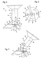
- FIGS. 6 and 7 show an embodiment of a chopper 31.
- the same reference numerals as in the FIGS. 1 to 5 identify the same components.
- the shredder 31 has a feed tube 33, which is rotatably mounted about a rotation axis 36.
- the axis of rotation 36 closes with the axis of rotation 12 of the cutter disk 10 at an angle ⁇ , which is formed as an acute angle.
- the angle ⁇ is advantageously between 0 ° and 45 °, in particular between 10 ° and 35 °.
- An angle ⁇ between 15 ° and 30 ° has been found.
- the feed tube 33 is rotatably mounted on a pipe socket 32 which is fixedly connected to the housing 2.
- the pipe socket 32 and the feed tube 33 are connected to one another at a connecting plane 34 which is inclined perpendicular to the axis of rotation 36 and to the plane of the cutter disk 10.
- the cutter disk 10 may be in Fig. 5 Shaped disc 10 correspond.
- a cover 38 is arranged, which in the in Fig. 6 shown first operating position 17 of the feed tube 33, the region of the cutter disk 10, in which the cutting blades 13 are arranged covers.
- Another cover 40 may be fixed to the housing 2, for example in the region of the pipe socket 32. This ensures that only Humbleburgtrieb the ripper 14 can come into engagement with good to be shredded.
- the cutting blade 13 and the razor 14 can be arranged so that all the knives 13, 14 come in the same direction of rotation with good to be shredded.
- the upper part of the housing 2 can be pivoted together with the feed tube 33 about a pivot axis 47.
- at least one locking button 37 is provided on the housing 2. By opening the lock button 37, the upper part of the housing 2 can be pivoted together with the feed tube 33 into an inoperative position, in which the area of the cutter disk 10 can be cleaned.
- the longitudinal center axis 35 of the feed tube 33 is approximately parallel to the axis of rotation 12 of the cutter disk 10.
- the feed tube 33 in the direction of in Fig. 6 shown arrow 39 is rotated about the axis of rotation 36.
- second operating position 18 includes the longitudinal center axis 35 with the rotation axis 12 an angle ⁇ , which is advantageously from 10 ° to 80 °, in particular from 20 ° to 70 ° and preferably from 30 ° to 60 °.
- the angle ⁇ by which the axis of rotation 36 is inclined relative to the axis of rotation 12 of the cutter disk 10, is half as large as the angle ⁇ .
- the housing-fixed cover 40 is arranged so that it does not hinder the accessibility of the cutting blade 13 in the second operating position 18 of the feed tube 33. Characterized in that the adjustment of the feed tube 33 and the position of at least one cover 38 is adjusted, it is ensured that in the first operating position 17 at Humbleburghorn shredding can only engage with the cutting blades 14 and in the second operating position 18 to be shredded branches and like. can only come with the cutting blades 13 and not with the cutting blades 14 into engagement. As a result, the cutting disc 10 can be driven in both operating modes in the same direction of rotation. However, it can also be a switching of the direction of rotation, for example, depending on the position of the feed tube 33 may be provided.
- FIGS. 8 and 9 Another embodiment is in the FIGS. 8 and 9 shown.
- the in the FIGS. 8 and 9 shown chopper 41 may according to the in Fig. 1 and Fig. 2 shown chopper 1 be constructed. Like reference numerals designate like components.
- the chopper 41 has a mode indicator 42, which is in the first operating position 17 of the feed tube 3 in a display position 44 for the first mode. This clarifies to the operator which is to be filled to be shredded.
- the chopper 41 may have a mode switch 43, with which the direction of rotation of the drive motor can be switched. Based on the mode displayed in the mode display 42, the operator can operate the mode switch 43.
- second operating position 18 of the feed tube 3 is the mode indicator 42 in a second display position 45 for the second mode, namely for the Schnitzel réelle. Again, the operator can operate the mode switch 43 accordingly.
- the chopper 41 in addition to the mode display 42 at least one in the FIGS. 3 and 4 shown Switch 21 has, which allows automatic switching of the direction of rotation of the drive motor 9. This eliminates an operator-operated mode switch 43.
- the mode indicator 42 may be formed both electrically and mechanically.
- the detection of the operating mode by detecting the position of the feed tube can be done electrically, for example via an electrical switch, or mechanically.
Landscapes
- Engineering & Computer Science (AREA)
- Food Science & Technology (AREA)
- Crushing And Pulverization Processes (AREA)
Claims (12)
- Broyeur avec un moteur d'entraînement (9) qui entraîne en rotation au moins une unité de déchiquetage, étant précisé qu'il est prévu au moins un tube d'alimentation (3, 33) pour alimenter l'unité de déchiquetage en produits à déchiqueter,
caractérisé en ce que la position du tube d'amenée (3, 33) est réglable entre une première position de fonctionnement (17) pour le mode de broyage du broyeur (1, 31, 41), et une seconde position de fonctionnement (18) pour le mode de coupe du broyeur (1, 31, 41), étant précisé que l'angle entre l'axe médian longitudinal (5, 35) du tube d'alimentation (3, 33) et l'axe de rotation (12) de l'unité de déchiquetage dans la première position de fonctionnement (17) est de moins de 5°, et que l'axe médian longitudinal (5, 35) du tube d'alimentation (3, 33) forme avec l'axe de rotation (12) de l'unité de déchiquetage dans la seconde position de fonctionnement (18) un angle (α) de 20° à 70°. - Broyeur selon la revendication 1,
caractérisé en ce que l'axe médian longitudinal (5, 35) du tube d'alimentation (3, 33), dans la première position de fonctionnement (17), est parallèle à l'axe de rotation (12) de l'unité de déchiquetage. - Broyeur selon la revendication 1 ou 2,
caractérisé en ce que le sens de rotation de l'unité de déchiquetage peut passer d'un premier sens de rotation (26) à un second sens de rotation (27) et inversement, étant précisé que chaque sens de rotation (26, 27) est associé à un mode de fonctionnement du broyeur (1, 31, 41). - Broyeur selon la revendication 3,
caractérisé en ce que le sens de rotation (26, 27) de l'unité de déchiquetage est commandé en fonction de la position de fonctionnement (17, 18) du tube d'alimentation (3, 33). - Broyeur selon l'une des revendications 1 à 4,
caractérisé en ce que le broyeur (41) présente un indicateur de mode de fonctionnement (42) qui indique le mode de fonctionnement du broyeur (41) en fonction de la position de fonctionnement (17, 18) du tube d'alimentation (3). - Broyeur selon l'une des revendications 1 à 5,
caractérisé en ce que le broyeur (31) présente au moins un recouvrement (38, 40) qui couvre une zone de l'unité de déchiquetage, dans une position de fonctionnement (17, 18) du tube d'alimentation (33), et qui dégage cette zone de l'unité de déchiquetage, dans une autre position de fonctionnement (17, 18). - Broyeur selon la revendication 6,
caractérisé en ce que la position du recouvrement (38) est commandée en fonction de la position de fonctionnement (17, 18) du tube d'alimentation (33). - Broyeur selon l'une des revendications 1 à 7,
caractérisé en ce que le broyeur (1, 31) comporte au moins un commutateur (21, 21') qui est actionné, dans une position de fonctionnement (17, 18) du tube d'alimentation (3, 33), et qui n'est pas actionné, dans l'autre position de fonctionnement (17, 18) du tube d'alimentation (3, 33). - Broyeur selon l'une des revendications 1 à 8,
caractérisé en ce que le broyeur (1) comporte au moins une butée (19, 20) pour bloquer une position de fonctionnement (17, 18) du tube d'alimentation (3). - Broyeur selon l'une des revendications 1 à 9,
caractérisé en ce que le tube d'alimentation (3) est apte à pivoter sur un axe de pivotement (15) à peu près perpendiculaire à l'axe de rotation (12) de l'unité de déchiquetage entre les positions de fonctionnement (17, 18). - Broyeur selon l'une des revendications 1 à 9,
caractérisé en ce que le tube d'alimentation (33) est apte à tourner entre les positions de fonctionnement (17, 18) sur un axe de rotation (36) qui est incliné d'un angle (β) par rapport à l'axe de rotation (12) de l'unité de déchiquetage. - Broyeur selon la revendication 11,
caractérisé en ce que le tube d'alimentation (33) est monté en rotation sur une tubulure (32) sur le carter (2) du broyeur (31), étant précisé que le tube d'alimentation (33) est monté sur la tubulure (32) dans un plan de liaison (34) qui est incliné par rapport à l'axe de rotation (12) de l'unité de déchiquetage.
Priority Applications (1)
| Application Number | Priority Date | Filing Date | Title |
|---|---|---|---|
| EP20070013650 EP2014371B1 (fr) | 2007-07-12 | 2007-07-12 | Hache |
Applications Claiming Priority (1)
| Application Number | Priority Date | Filing Date | Title |
|---|---|---|---|
| EP20070013650 EP2014371B1 (fr) | 2007-07-12 | 2007-07-12 | Hache |
Publications (2)
| Publication Number | Publication Date |
|---|---|
| EP2014371A1 EP2014371A1 (fr) | 2009-01-14 |
| EP2014371B1 true EP2014371B1 (fr) | 2013-11-06 |
Family
ID=38786873
Family Applications (1)
| Application Number | Title | Priority Date | Filing Date |
|---|---|---|---|
| EP20070013650 Active EP2014371B1 (fr) | 2007-07-12 | 2007-07-12 | Hache |
Country Status (1)
| Country | Link |
|---|---|
| EP (1) | EP2014371B1 (fr) |
Families Citing this family (1)
| Publication number | Priority date | Publication date | Assignee | Title |
|---|---|---|---|---|
| DE102015011437A1 (de) * | 2015-09-01 | 2017-03-02 | Julius Tielbürger GmbH & Co. KG | Gartenhäcksler mit einem Fahrgestell |
Family Cites Families (3)
| Publication number | Priority date | Publication date | Assignee | Title |
|---|---|---|---|---|
| DE8618942U1 (de) * | 1986-07-15 | 1986-10-02 | Alois Kober KG, 8871 Kötz | Zerkleinerungsgerät für Pflanzenreste |
| DE8810996U1 (fr) * | 1987-09-03 | 1988-10-20 | Johmann Sen., Bruno, 6951 Limbach, De | |
| DE20321100U1 (de) * | 2003-05-20 | 2006-01-05 | Tuschl, Robert | Vorrichtung zur Zerkleinerung von schneidbaren Materialien |
-
2007
- 2007-07-12 EP EP20070013650 patent/EP2014371B1/fr active Active
Also Published As
| Publication number | Publication date |
|---|---|
| EP2014371A1 (fr) | 2009-01-14 |
Similar Documents
| Publication | Publication Date | Title |
|---|---|---|
| DE2258841C3 (de) | Elektrische schneidemaschine fuer lebensmittel | |
| EP0346661B1 (fr) | Appareil hacheur découpeur | |
| DD297541A5 (de) | Haecksler | |
| DE19749338C2 (de) | Häcksler zum Zerkleinern von Halmgut, vorzugsweise von Stroh | |
| EP1255612A1 (fr) | Procede et dispositif pour broyer des copeaux | |
| EP2386200A1 (fr) | Ramasseuse-hacheuse automobile | |
| EP1442796B1 (fr) | Dispositif de broyage | |
| EP2014371B1 (fr) | Hache | |
| DE4328506C1 (de) | Spänebrecher | |
| DE3335719C1 (de) | Sicherheitsverriegelung fuer Schneidmuehlen | |
| EP1852011B1 (fr) | Ramasseuse-hacheuse automobile | |
| EP1935595B1 (fr) | Dispositif et procédé pour déchiqueter des troncs d'arbre | |
| DE102019108306A1 (de) | Schneidmühle zum schneidenden Zerkleinern von Proben | |
| DE3340136A1 (de) | Zerkleinerungs- und mischmaschine fuer biologisches und organisches zerkleinerungsgut | |
| EP0380811B1 (fr) | Broyeur à impact | |
| DE4406675A1 (de) | Vorrichtung zum schneidenden Zerkleinern von Materialien | |
| EP1547459B1 (fr) | Disque de coupe avec dents déchirantes pour un broyeur | |
| EP2564930B1 (fr) | Hache | |
| EP2944441A1 (fr) | Trancheuse mandoline | |
| WO2003106035A1 (fr) | Machine a emincer de la matiere | |
| DE3527772A1 (de) | Vorrichtung zum zerkleinern von abfaellen | |
| EP0620762B1 (fr) | Broyeur et element tranchant pour broyeur | |
| EP1967271B1 (fr) | Lame de couteau | |
| EP1289662A1 (fr) | Cisaille-guillotine | |
| EP0943278B1 (fr) | Appareil de cuisine |
Legal Events
| Date | Code | Title | Description |
|---|---|---|---|
| PUAI | Public reference made under article 153(3) epc to a published international application that has entered the european phase |
Free format text: ORIGINAL CODE: 0009012 |
|
| AK | Designated contracting states |
Kind code of ref document: A1 Designated state(s): AT BE BG CH CY CZ DE DK EE ES FI FR GB GR HU IE IS IT LI LT LU LV MC MT NL PL PT RO SE SI SK TR |
|
| AX | Request for extension of the european patent |
Extension state: AL BA HR MK RS |
|
| 17P | Request for examination filed |
Effective date: 20090617 |
|
| AKX | Designation fees paid |
Designated state(s): AT BE DE ES FR GB |
|
| 17Q | First examination report despatched |
Effective date: 20100326 |
|
| APBK | Appeal reference recorded |
Free format text: ORIGINAL CODE: EPIDOSNREFNE |
|
| APBN | Date of receipt of notice of appeal recorded |
Free format text: ORIGINAL CODE: EPIDOSNNOA2E |
|
| APBR | Date of receipt of statement of grounds of appeal recorded |
Free format text: ORIGINAL CODE: EPIDOSNNOA3E |
|
| APAF | Appeal reference modified |
Free format text: ORIGINAL CODE: EPIDOSCREFNE |
|
| APBT | Appeal procedure closed |
Free format text: ORIGINAL CODE: EPIDOSNNOA9E |
|
| GRAP | Despatch of communication of intention to grant a patent |
Free format text: ORIGINAL CODE: EPIDOSNIGR1 |
|
| INTG | Intention to grant announced |
Effective date: 20130624 |
|
| GRAS | Grant fee paid |
Free format text: ORIGINAL CODE: EPIDOSNIGR3 |
|
| GRAA | (expected) grant |
Free format text: ORIGINAL CODE: 0009210 |
|
| AK | Designated contracting states |
Kind code of ref document: B1 Designated state(s): AT BE DE ES FR GB |
|
| REG | Reference to a national code |
Ref country code: GB Ref legal event code: FG4D Free format text: NOT ENGLISH |
|
| REG | Reference to a national code |
Ref country code: AT Ref legal event code: REF Ref document number: 639065 Country of ref document: AT Kind code of ref document: T Effective date: 20131215 |
|
| REG | Reference to a national code |
Ref country code: DE Ref legal event code: R096 Ref document number: 502007012452 Country of ref document: DE Effective date: 20140102 |
|
| PG25 | Lapsed in a contracting state [announced via postgrant information from national office to epo] |
Ref country code: ES Free format text: LAPSE BECAUSE OF FAILURE TO SUBMIT A TRANSLATION OF THE DESCRIPTION OR TO PAY THE FEE WITHIN THE PRESCRIBED TIME-LIMIT Effective date: 20131106 |
|
| REG | Reference to a national code |
Ref country code: DE Ref legal event code: R097 Ref document number: 502007012452 Country of ref document: DE |
|
| PLBE | No opposition filed within time limit |
Free format text: ORIGINAL CODE: 0009261 |
|
| STAA | Information on the status of an ep patent application or granted ep patent |
Free format text: STATUS: NO OPPOSITION FILED WITHIN TIME LIMIT |
|
| 26N | No opposition filed |
Effective date: 20140807 |
|
| REG | Reference to a national code |
Ref country code: DE Ref legal event code: R097 Ref document number: 502007012452 Country of ref document: DE Effective date: 20140807 |
|
| REG | Reference to a national code |
Ref country code: AT Ref legal event code: MM01 Ref document number: 639065 Country of ref document: AT Kind code of ref document: T Effective date: 20140712 |
|
| PG25 | Lapsed in a contracting state [announced via postgrant information from national office to epo] |
Ref country code: AT Free format text: LAPSE BECAUSE OF NON-PAYMENT OF DUE FEES Effective date: 20140712 |
|
| REG | Reference to a national code |
Ref country code: FR Ref legal event code: PLFP Year of fee payment: 10 |
|
| PG25 | Lapsed in a contracting state [announced via postgrant information from national office to epo] |
Ref country code: BE Free format text: LAPSE BECAUSE OF FAILURE TO SUBMIT A TRANSLATION OF THE DESCRIPTION OR TO PAY THE FEE WITHIN THE PRESCRIBED TIME-LIMIT Effective date: 20140731 |
|
| REG | Reference to a national code |
Ref country code: FR Ref legal event code: PLFP Year of fee payment: 11 |
|
| REG | Reference to a national code |
Ref country code: FR Ref legal event code: PLFP Year of fee payment: 12 |
|
| REG | Reference to a national code |
Ref country code: DE Ref legal event code: R082 Ref document number: 502007012452 Country of ref document: DE Representative=s name: PATENTANWAELTE DIPL.-ING. W. JACKISCH & PARTNE, DE Ref country code: DE Ref legal event code: R082 Ref document number: 502007012452 Country of ref document: DE Representative=s name: PATENTANWAELTE DIPL.-ING. WALTER JACKISCH & PA, DE Ref country code: DE Ref legal event code: R081 Ref document number: 502007012452 Country of ref document: DE Owner name: ANDREAS STIHL AG & CO. KG, DE Free format text: FORMER OWNER: VIKING GMBH, LANGKAMPFEN, AT |
|
| REG | Reference to a national code |
Ref country code: GB Ref legal event code: 732E Free format text: REGISTERED BETWEEN 20180927 AND 20181005 |
|
| PGFP | Annual fee paid to national office [announced via postgrant information from national office to epo] |
Ref country code: GB Payment date: 20230725 Year of fee payment: 17 |
|
| PGFP | Annual fee paid to national office [announced via postgrant information from national office to epo] |
Ref country code: FR Payment date: 20230725 Year of fee payment: 17 Ref country code: DE Payment date: 20230726 Year of fee payment: 17 |