EP2014150B1 - Ballenpresse mit Bindematerialversorgung - Google Patents
Ballenpresse mit Bindematerialversorgung Download PDFInfo
- Publication number
- EP2014150B1 EP2014150B1 EP08011749A EP08011749A EP2014150B1 EP 2014150 B1 EP2014150 B1 EP 2014150B1 EP 08011749 A EP08011749 A EP 08011749A EP 08011749 A EP08011749 A EP 08011749A EP 2014150 B1 EP2014150 B1 EP 2014150B1
- Authority
- EP
- European Patent Office
- Prior art keywords
- roller
- binding
- binding material
- baling press
- feeding unit
- Prior art date
- Legal status (The legal status is an assumption and is not a legal conclusion. Google has not performed a legal analysis and makes no representation as to the accuracy of the status listed.)
- Active
Links
Images
Classifications
-
- A—HUMAN NECESSITIES
- A01—AGRICULTURE; FORESTRY; ANIMAL HUSBANDRY; HUNTING; TRAPPING; FISHING
- A01F—PROCESSING OF HARVESTED PRODUCE; HAY OR STRAW PRESSES; DEVICES FOR STORING AGRICULTURAL OR HORTICULTURAL PRODUCE
- A01F15/00—Baling presses for straw, hay or the like
- A01F15/07—Rotobalers, i.e. machines for forming cylindrical bales by winding and pressing
- A01F15/071—Wrapping devices
- A01F15/0715—Wrapping the bale in the press chamber before opening said chamber
Definitions
- the present invention relates to a baler for pressing agricultural crop having a baling chamber having at least one roller coupled to rotation of a bale in the baling chamber, a binder dispenser, a binder feed unit for feeding binder material dispensed from the binder dispenser to an inlet gap of the baling chamber and a capping device for severing the binding material, wherein the binding material conveying unit is movable between a rest position and a working position.
- a baler is out US Pat. No. 6,981,352 B2 ( US 2004 016204 A1 ) known.
- the object of the present invention is to provide a binder with binding material supply, in which the insertion of the binding material into the pressing chamber at the beginning of a binding process succeeds with high reliability.
- the binder material conveying unit having a drive roller in a baling press of the type specified, which is driven in the working position by non-positive contact, in particular frictional contact, with the role of the pressing chamber and is parked in the rest position of the roller of the pressing chamber.
- the binding material feed unit is driven via the drive roller, the binding material from the conveyor unit can be actively inserted into the gap of the pressing chamber, so that it does not matter if and how far already when moving to the working position, a leading portion of the binding material over the top of the Binder material delivery unit survives.
- the capping means is coupled to the movement of the binding material conveying unit between the rest position and the operative position to cap the binding material upon reaching the rest position.
- a separate motor for the capping is then not required.
- the binding material conveying unit preferably comprises a frame carrying at least one roller wrapped in the binding material and an arm supporting the drive roller pivotally connected to the frame about the axis of the roller and via which the drive roller is rotationally coupled to the roller is.
- the looped roller is rotated as soon as the drive roller has come into frictional contact with the roller of the pressing chamber.
- the drive roller and the looped roller are preferably coupled together by a belt or chain drive.
- the looped roller In order to reliably drive the binding material even when it is not under tension and thereby pressed against the looped roller limited the looped roller preferably together with a counterpressure roller a gap clamping the binding material.
- the peripheral speed of the driven roller driven over the drive roller is preferably smaller than that of the bale, and a freewheel is arranged between the drive roller and the looped roller, to enable it to rotate at a higher peripheral speed once the binding material has been caught by the bale rotating in the bale chamber and taken along.
- the roller of the pressing chamber is driven via a freewheel, which allows rotation of the looped roller at a higher peripheral speed.
- the binding material conveying unit In order to move the binding material conveying unit between the rest position and the working position, the binding material conveying unit is preferably pivotable about a second roller wrapped by the binding material. Such a pivoting movement allows an adjustment of the binding material conveying unit between the rest position and working position virtually without a related movement of the leading end of the binding material with respect to the tip of the conveyor unit. There is therefore no danger that due to the movement between Working and rest position shifts the binding material in the conveyor unit.
- the capping means may comprise, in a manner known per se, a knife pivotable about an axis.
- a cam track member is preferably further provided, which is rotatably connected to the knife and is engaged with the binding material conveying unit. Such a cam member may serve to drive the knife coupled to the movement of the binding material conveying unit between working and rest position.
- the binding material conveying unit is closer to the axis of the knife in the rest position than in the working position.
- the lever arm between the cam track member and the engaging therewith binding material conveying unit towards the end of its movement into the rest position becomes shorter and shorter. Accordingly, the knife becomes faster towards the end of the movement to the rest position and can penetrate the binding material strand well.
- the capping means is arranged to sever the binding material within the binding material conveying unit.
- the capping means is arranged to sever the binding material within the binding material conveying unit.
- the tip of the binding material conveying unit is formed by a guide plate, on the underside of the binding material is guided along, and in the rest position, the capping device cuts through the binding material on the guide plate.
- the binding material does not have to protrude beyond the tip of the guide plate, it can reliably penetrate even in the gap of the pressing chamber against any resistance and place the leading end of the binding material strand there.
- the leading end of the binder web is close enough to the tip to subsequently, when the binder web is driven, reliably find the path through the nip.
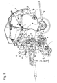
- Round baler shown in side view has a housing 2 surrounding a pressing chamber 1 and a Erntegutier philosophical 3 for collecting cut crop from the ground and feeding the crop to the pressing chamber 1.
- a rotating knife roller 5 arranged for crushing the crop.
- the knife roller 5 conveys the crop through an inlet gap 6 between two rollers 7, 8 in the pressing chamber.
- the pressing chamber is limited in a conventional manner by two sets of endless belts 9, which rotate on rollers. Of these rollers, at least some, designated by 10 in the figure, are movable in order to adapt the size of the pressing chamber 1 to a pressing bale 11 formed therein from the crop.
- the pressed bale 11 When the pressed bale 11 has reached a target size, it must be output from the press. For this purpose, it is first wrapped with a binding material to prevent the billet 11 outside the press dissolves again, then a rear half of the housing 2 is folded up, so that the bale 11 from the press out a ramp 12 to the ground can roll.
- the binding material used may be different, for example a net, a foil or a yarn.
- a supply roll 13 of the binding material is mounted in a binding material dispenser 14 on the front side of the housing 2.
- the binding material dispenser 14 comprises a plurality of rollers 15, on which the supply roll 13 stably rests, and a height-adjustable semi-trailer 16, which in Fig. 1 is shown spaced from the supply roll 13, but in operation rests on the supply roll 13 to prevent them from being ejected by occurring during the movement of the baler vibrations from a depression formed by the rollers 15.
- a binding material web 17 extends from the dispenser 14 through a chicane 18 to a binding material conveyor 19.
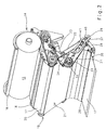
- the binding material dispenser 14, the chicane 18 and the binding material conveyor 19 are shown in FIG Fig. 2 and 3 each shown in a perspective view and a side view.
- the baffle 18 comprises three small-diameter rollers between which the binder material web 17 is passed under directional changes. It serves to equalize the running and tension of the binding material web 17 during the wrapping of the pressing bale 11 with the binding material.
- One of the binder material web 17 wrapped roller 20 with respect to the housing 2 fixed axis forms the entrance of the binding material conveyor 19.
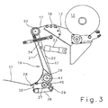
- Two between them a curved guide plate 21 supporting arms 22 are about the axis of the roller 20, driven by a hydraulic actuator 23, between a in Fig. 1 shown rest position and a working position in which a remote from the roller 20 lower edge 28 of the guide plate 21 engages in a gap 24 between the roller 7 and a looped by the belt 9 roller 25. While the pressed bale 11 is formed, the arms 22 are in the rest position, so that the gap 24 is open, and pressed material, by the reference to Fig.
- FIG. 3 shows the binding material web 17 from the stationary roller 20 via a side facing away from the pressing chamber 1 side of the guide plate 21 steeply down to one of the rubberized roller 26 carried around the arms 22, around it and through a nip between the rubberized roller 26 and a counter-pressure roller 27 also carried by the arms 22, and from there on a gently sloping path to the lower edge 28.
- one arm 31 is pivoted about the axis 41 of the rubberized roller 26 to one of the arms 22 an arm.
- the arm 31 carries at its free end a friction roller 32 and a hand wheel 33.
- the friction roller 32 and the handwheel 33 are rotatably connected to each other and rotatably coupled via a concealed in the interior of the arm 31 chain or belt drive to the rubberized roller 26.
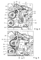
- the friction roller 32 has a slightly smaller diameter than the handwheel 33 and is therefore in the side view of Fig. 4 obscured by the latter.
- a spring 34 spreads the free upper end of the arm 31 from the arm 22.
- the hydraulic actuator 23 is extended to the binding material conveyor 19 from the rest position of the Fig. 1 or 4 in their in Fig. 5 shown working position, in which the lower Edge of the guide plate 21 engages in the gap 24.
- the binding material conveyor 19 in the working position their friction roller 32 comes into frictional contact with a complementary friction roller 35, which via a toothed belt 36 or a chain (see Fig. 1 ) is rotationally coupled to the roller 25.
- the rubberized roller 26 is coupled to the orbital motion of the belt 9 and is thereby rotationally driven. Characterized the clamped in the gap between the rubberized roller 26 and the platen roller 27 binding material web 17 is conveyed forward.
- a freewheel is provided, which ensures the transmission of the rotation of the shaft 43 to the roller 26, but allows rotation of the roller 26 without a corresponding rotation of the shaft 43.
- the freewheel is of any, known per se and can be at any suitable location, eg. B may be placed on the arm 31 or inside the friction roller 35 and is therefore not specifically shown in the figures.
- the pivoting freedom and the dimensions of the arm 31 are selected so that the frictional engagement between the rollers 32, 35 is generated only when the lower edge 28 of the guide plate 21 and with it the tip of the binding material web 17 dips into the gap 24. The then on the edge 28 of the guide plate 21 advancing tip of the Binder material web 17 is detected by the rotating clockwise roller 7 and taken to the pressed bales 11. In the course of one or more revolutions of the press bale 11 is completely enveloped by the binding material.
- a capping device for separating the binder material web 17 wound around the pressed bales comprises an arm 38, which is pivotable about a housing-fixed axis 29 and which carries a knife blade 30.
- the axis 29 is closely adjacent to the rollers 26, 27, and the arm 38 extends substantially parallel to the course of the binding material web 17 between the rollers 26, 27 on the one hand and the lower edge 28 on the other hand, so that the knife blade 30 shortly before the lower edge 28 strikes the binding material web 17.
- the actuator 23 pulls the binding material conveyor 19 into the inoperative position of FIG Fig. 1 respectively.
- Fig. 4 back.
- the movement of the knife blade 30 is coupled about the axis 29 to the movement of the binding material conveyor 19 between working and rest position by a cam member 37 which is rotatably connected to the knife blade 30 supporting arm 38 and has a curved path 39, in the a protruding from one of the arms 22 and a roller bearing pin 40 engages. While the binding material conveyor 19 in the working position of Fig.
- the pin 40 at an off-axis end of the cam track 39; in the resting position of Fig. 4
- the cam track 39 has a circular arc-shaped off-axis portion, which is centered in the working position on the roller 20, and a radially aligned to the axis 29 portion. If, during the transition from the working to the rest position of the pin passes through the arcuate portion, the cam member 37 remains at rest; only when the pin 40 reaches the radial portion, the curved track member and with it the knife blade 30 begins to pivot.
- the press bale 11 is further rotated after cutting the binder material web 17 between the belt 9 until the rear end of the cut binding material portion on the pressed bales 11 wound up. Then, the case 2 can be opened and the press bale 11 can be discharged, and the generation of a new press bale can begin.
Landscapes
- Life Sciences & Earth Sciences (AREA)
- Environmental Sciences (AREA)
- Basic Packing Technique (AREA)
- Press Drives And Press Lines (AREA)
- Catching Or Destruction (AREA)
Priority Applications (1)
| Application Number | Priority Date | Filing Date | Title |
|---|---|---|---|
| PL08011749T PL2014150T3 (pl) | 2007-07-12 | 2008-06-28 | Prasa do belowania z dostarczaniem materiału opakowaniowego |
Applications Claiming Priority (1)
| Application Number | Priority Date | Filing Date | Title |
|---|---|---|---|
| DE102007032859A DE102007032859A1 (de) | 2007-07-12 | 2007-07-12 | Ballenpresse mit Bindematerialversorgung |
Publications (2)
| Publication Number | Publication Date |
|---|---|
| EP2014150A1 EP2014150A1 (de) | 2009-01-14 |
| EP2014150B1 true EP2014150B1 (de) | 2010-07-21 |
Family
ID=39791771
Family Applications (1)
| Application Number | Title | Priority Date | Filing Date |
|---|---|---|---|
| EP08011749A Active EP2014150B1 (de) | 2007-07-12 | 2008-06-28 | Ballenpresse mit Bindematerialversorgung |
Country Status (4)
| Country | Link |
|---|---|
| EP (1) | EP2014150B1 (pl) |
| AT (1) | ATE474451T1 (pl) |
| DE (2) | DE102007032859A1 (pl) |
| PL (1) | PL2014150T3 (pl) |
Families Citing this family (6)
| Publication number | Priority date | Publication date | Assignee | Title |
|---|---|---|---|---|
| IES20090710A2 (en) * | 2009-09-17 | 2011-03-30 | Welmount Ltd | A baler |
| DE102012006833B9 (de) * | 2012-04-03 | 2013-12-24 | Maschinenfabrik Bernard Krone Gmbh | Rundballenpresse |
| BE1021149B1 (nl) * | 2013-05-27 | 2016-01-19 | Cnh Industrial Belgium Nv | Baalinwikkelmechanisme |
| DE202015003273U1 (de) * | 2015-05-04 | 2016-08-05 | Alois Pöttinger Maschinenfabrik Ges.m.b.H. | Ballenpresse für landwirtschaftliches Erntegut |
| CN112027756B (zh) * | 2020-09-16 | 2025-06-03 | 太古农业科技(南通)有限公司 | 一种薄膜牵引传送的导向机构 |
| EP4091434A1 (en) * | 2021-05-10 | 2022-11-23 | AGCO International GmbH | Baling apparatus |
Family Cites Families (4)
| Publication number | Priority date | Publication date | Assignee | Title |
|---|---|---|---|---|
| US4956968A (en) * | 1989-12-11 | 1990-09-18 | Ford New Holland, Inc. | Round baler with mechanism for dispensing wrapping material |
| US6209450B1 (en) * | 1998-08-03 | 2001-04-03 | New Holland North America, Inc. | Round baler with improved twine wrap control |
| US6981352B2 (en) | 2002-07-26 | 2006-01-03 | Cnh America Llc | Round baler low net indication |
| ITRM20040176A1 (it) * | 2004-04-07 | 2004-07-07 | Ohg Ing A Ferabol I S P A | Dispositivo di legatura di una balla di foraggio o simili, mediante una rete o un foglio di altro materiale. |
-
2007
- 2007-07-12 DE DE102007032859A patent/DE102007032859A1/de not_active Withdrawn
-
2008
- 2008-06-28 DE DE502008000975T patent/DE502008000975D1/de active Active
- 2008-06-28 AT AT08011749T patent/ATE474451T1/de active
- 2008-06-28 EP EP08011749A patent/EP2014150B1/de active Active
- 2008-06-28 PL PL08011749T patent/PL2014150T3/pl unknown
Also Published As
| Publication number | Publication date |
|---|---|
| EP2014150A1 (de) | 2009-01-14 |
| PL2014150T3 (pl) | 2011-03-31 |
| DE502008000975D1 (de) | 2010-09-02 |
| DE102007032859A1 (de) | 2009-01-15 |
| ATE474451T1 (de) | 2010-08-15 |
Similar Documents
| Publication | Publication Date | Title |
|---|---|---|
| DE69102990T2 (de) | Anbringervorrichtung für umhüllnetz in eine rundballenpresse. | |
| DE69709981T2 (de) | Rundballenpresse | |
| DE69323738T2 (de) | Ballenpresszuführmechanismus | |
| EP2014150B1 (de) | Ballenpresse mit Bindematerialversorgung | |
| DE69909188T2 (de) | Umhüllungsvorrichtung für Rundballen | |
| DE602005000693T2 (de) | Doppelknotensystem für landwirtschaftliche Ballenpresse | |
| EP1064839B1 (de) | Vorrichtung zum Sichern eines losen Garnendes auf einem Rundballen | |
| DE19849936B4 (de) | Verfahren und Vorrichtung zum Entfernen einer Hülle von einem in der Hülle befindlichen Lebensmittel | |
| DE60317998T2 (de) | Vorrichtung zum Umreifen mit verbesserter Spanntrommel | |
| DE19822359C1 (de) | Rundballenpresse für landwirtschaftliches Erntegut | |
| EP0535532A2 (de) | Verfahren zum Binden eines Ballens und Vorrichtung hierfür | |
| EP2767153B1 (de) | Rundballenpresse | |
| EP1813145B1 (de) | Vorrichtung zum Umhüllen eines Ballens mit einer Hüllbahn und Ballenpresse | |
| DE2530320C3 (de) | Bindevorrichtung für Wickelballenpressen | |
| DE102005055375B4 (de) | Rundballenpresse | |
| EP1254761B1 (de) | Rundballenpresse für Abfallmaterialien | |
| EP1829445A1 (de) | Ballenpresse | |
| EP1219419B1 (de) | Vorrichtung zum Zu- und Abführen von Druckplatten auf den Plattenzylinder von Druckmaschinen | |
| EP3501261B1 (de) | Leitmittel, ballenpresse und verfahren | |
| DE3002988C2 (pl) | ||
| EP1614341B1 (de) | Rückhaltemittel für das Bindemittel an Rundballenpressen | |
| EP1745691B1 (de) | Garnknoter, insbesondere für Ballenpressen | |
| EP1099367B1 (de) | Hüllmittelzufuhrvorrichtung | |
| EP0858734A1 (de) | Rundballenpresse | |
| DE19720542A1 (de) | Vorrichtung und Verfahren zur Sicherung von Garnenden |
Legal Events
| Date | Code | Title | Description |
|---|---|---|---|
| PUAI | Public reference made under article 153(3) epc to a published international application that has entered the european phase |
Free format text: ORIGINAL CODE: 0009012 |
|
| 17P | Request for examination filed |
Effective date: 20081128 |
|
| AK | Designated contracting states |
Kind code of ref document: A1 Designated state(s): AT BE BG CH CY CZ DE DK EE ES FI FR GB GR HR HU IE IS IT LI LT LU LV MC MT NL NO PL PT RO SE SI SK TR |
|
| AX | Request for extension of the european patent |
Extension state: AL BA MK RS |
|
| AKX | Designation fees paid |
Designated state(s): AT BE BG CH CY CZ DE DK EE ES FI FR GB GR HR HU IE IS IT LI LT LU LV MC MT NL NO PL PT RO SE SI SK TR |
|
| GRAP | Despatch of communication of intention to grant a patent |
Free format text: ORIGINAL CODE: EPIDOSNIGR1 |
|
| GRAS | Grant fee paid |
Free format text: ORIGINAL CODE: EPIDOSNIGR3 |
|
| GRAA | (expected) grant |
Free format text: ORIGINAL CODE: 0009210 |
|
| AK | Designated contracting states |
Kind code of ref document: B1 Designated state(s): AT BE BG CH CY CZ DE DK EE ES FI FR GB GR HR HU IE IS IT LI LT LU LV MC MT NL NO PL PT RO SE SI SK TR |
|
| REG | Reference to a national code |
Ref country code: GB Ref legal event code: FG4D Free format text: NOT ENGLISH |
|
| REG | Reference to a national code |
Ref country code: CH Ref legal event code: EP |
|
| REG | Reference to a national code |
Ref country code: IE Ref legal event code: FG4D |
|
| REF | Corresponds to: |
Ref document number: 502008000975 Country of ref document: DE Date of ref document: 20100902 Kind code of ref document: P |
|
| REG | Reference to a national code |
Ref country code: NL Ref legal event code: VDEP Effective date: 20100721 |
|
| LTIE | Lt: invalidation of european patent or patent extension |
Effective date: 20100721 |
|
| PG25 | Lapsed in a contracting state [announced via postgrant information from national office to epo] |
Ref country code: NO Free format text: LAPSE BECAUSE OF FAILURE TO SUBMIT A TRANSLATION OF THE DESCRIPTION OR TO PAY THE FEE WITHIN THE PRESCRIBED TIME-LIMIT Effective date: 20101021 Ref country code: NL Free format text: LAPSE BECAUSE OF FAILURE TO SUBMIT A TRANSLATION OF THE DESCRIPTION OR TO PAY THE FEE WITHIN THE PRESCRIBED TIME-LIMIT Effective date: 20100721 Ref country code: FI Free format text: LAPSE BECAUSE OF FAILURE TO SUBMIT A TRANSLATION OF THE DESCRIPTION OR TO PAY THE FEE WITHIN THE PRESCRIBED TIME-LIMIT Effective date: 20100721 Ref country code: LT Free format text: LAPSE BECAUSE OF FAILURE TO SUBMIT A TRANSLATION OF THE DESCRIPTION OR TO PAY THE FEE WITHIN THE PRESCRIBED TIME-LIMIT Effective date: 20100721 |
|
| REG | Reference to a national code |
Ref country code: IE Ref legal event code: FD4D |
|
| PG25 | Lapsed in a contracting state [announced via postgrant information from national office to epo] |
Ref country code: IS Free format text: LAPSE BECAUSE OF FAILURE TO SUBMIT A TRANSLATION OF THE DESCRIPTION OR TO PAY THE FEE WITHIN THE PRESCRIBED TIME-LIMIT Effective date: 20101121 Ref country code: CY Free format text: LAPSE BECAUSE OF FAILURE TO SUBMIT A TRANSLATION OF THE DESCRIPTION OR TO PAY THE FEE WITHIN THE PRESCRIBED TIME-LIMIT Effective date: 20100721 Ref country code: HR Free format text: LAPSE BECAUSE OF FAILURE TO SUBMIT A TRANSLATION OF THE DESCRIPTION OR TO PAY THE FEE WITHIN THE PRESCRIBED TIME-LIMIT Effective date: 20100721 Ref country code: SI Free format text: LAPSE BECAUSE OF FAILURE TO SUBMIT A TRANSLATION OF THE DESCRIPTION OR TO PAY THE FEE WITHIN THE PRESCRIBED TIME-LIMIT Effective date: 20100721 Ref country code: BG Free format text: LAPSE BECAUSE OF FAILURE TO SUBMIT A TRANSLATION OF THE DESCRIPTION OR TO PAY THE FEE WITHIN THE PRESCRIBED TIME-LIMIT Effective date: 20101021 |
|
| PG25 | Lapsed in a contracting state [announced via postgrant information from national office to epo] |
Ref country code: SE Free format text: LAPSE BECAUSE OF FAILURE TO SUBMIT A TRANSLATION OF THE DESCRIPTION OR TO PAY THE FEE WITHIN THE PRESCRIBED TIME-LIMIT Effective date: 20100721 Ref country code: GR Free format text: LAPSE BECAUSE OF FAILURE TO SUBMIT A TRANSLATION OF THE DESCRIPTION OR TO PAY THE FEE WITHIN THE PRESCRIBED TIME-LIMIT Effective date: 20101022 Ref country code: LV Free format text: LAPSE BECAUSE OF FAILURE TO SUBMIT A TRANSLATION OF THE DESCRIPTION OR TO PAY THE FEE WITHIN THE PRESCRIBED TIME-LIMIT Effective date: 20100721 |
|
| REG | Reference to a national code |
Ref country code: PL Ref legal event code: T3 |
|
| PG25 | Lapsed in a contracting state [announced via postgrant information from national office to epo] |
Ref country code: IE Free format text: LAPSE BECAUSE OF FAILURE TO SUBMIT A TRANSLATION OF THE DESCRIPTION OR TO PAY THE FEE WITHIN THE PRESCRIBED TIME-LIMIT Effective date: 20100721 Ref country code: DK Free format text: LAPSE BECAUSE OF FAILURE TO SUBMIT A TRANSLATION OF THE DESCRIPTION OR TO PAY THE FEE WITHIN THE PRESCRIBED TIME-LIMIT Effective date: 20100721 |
|
| PLBE | No opposition filed within time limit |
Free format text: ORIGINAL CODE: 0009261 |
|
| STAA | Information on the status of an ep patent application or granted ep patent |
Free format text: STATUS: NO OPPOSITION FILED WITHIN TIME LIMIT |
|
| PG25 | Lapsed in a contracting state [announced via postgrant information from national office to epo] |
Ref country code: CZ Free format text: LAPSE BECAUSE OF FAILURE TO SUBMIT A TRANSLATION OF THE DESCRIPTION OR TO PAY THE FEE WITHIN THE PRESCRIBED TIME-LIMIT Effective date: 20100721 Ref country code: EE Free format text: LAPSE BECAUSE OF FAILURE TO SUBMIT A TRANSLATION OF THE DESCRIPTION OR TO PAY THE FEE WITHIN THE PRESCRIBED TIME-LIMIT Effective date: 20100721 Ref country code: RO Free format text: LAPSE BECAUSE OF FAILURE TO SUBMIT A TRANSLATION OF THE DESCRIPTION OR TO PAY THE FEE WITHIN THE PRESCRIBED TIME-LIMIT Effective date: 20100721 Ref country code: SK Free format text: LAPSE BECAUSE OF FAILURE TO SUBMIT A TRANSLATION OF THE DESCRIPTION OR TO PAY THE FEE WITHIN THE PRESCRIBED TIME-LIMIT Effective date: 20100721 Ref country code: IT Free format text: LAPSE BECAUSE OF FAILURE TO SUBMIT A TRANSLATION OF THE DESCRIPTION OR TO PAY THE FEE WITHIN THE PRESCRIBED TIME-LIMIT Effective date: 20100721 |
|
| 26N | No opposition filed |
Effective date: 20110426 |
|
| PG25 | Lapsed in a contracting state [announced via postgrant information from national office to epo] |
Ref country code: ES Free format text: LAPSE BECAUSE OF FAILURE TO SUBMIT A TRANSLATION OF THE DESCRIPTION OR TO PAY THE FEE WITHIN THE PRESCRIBED TIME-LIMIT Effective date: 20101101 |
|
| REG | Reference to a national code |
Ref country code: DE Ref legal event code: R097 Ref document number: 502008000975 Country of ref document: DE Effective date: 20110426 |
|
| PG25 | Lapsed in a contracting state [announced via postgrant information from national office to epo] |
Ref country code: MT Free format text: LAPSE BECAUSE OF FAILURE TO SUBMIT A TRANSLATION OF THE DESCRIPTION OR TO PAY THE FEE WITHIN THE PRESCRIBED TIME-LIMIT Effective date: 20100721 |
|
| REG | Reference to a national code |
Ref country code: CH Ref legal event code: PL |
|
| REG | Reference to a national code |
Ref country code: CH Ref legal event code: PL |
|
| GBPC | Gb: european patent ceased through non-payment of renewal fee |
Effective date: 20120628 |
|
| PG25 | Lapsed in a contracting state [announced via postgrant information from national office to epo] |
Ref country code: LI Free format text: LAPSE BECAUSE OF NON-PAYMENT OF DUE FEES Effective date: 20120630 Ref country code: GB Free format text: LAPSE BECAUSE OF NON-PAYMENT OF DUE FEES Effective date: 20120628 Ref country code: MC Free format text: LAPSE BECAUSE OF NON-PAYMENT OF DUE FEES Effective date: 20110630 Ref country code: CH Free format text: LAPSE BECAUSE OF NON-PAYMENT OF DUE FEES Effective date: 20120630 |
|
| PG25 | Lapsed in a contracting state [announced via postgrant information from national office to epo] |
Ref country code: LU Free format text: LAPSE BECAUSE OF NON-PAYMENT OF DUE FEES Effective date: 20110628 |
|
| PG25 | Lapsed in a contracting state [announced via postgrant information from national office to epo] |
Ref country code: TR Free format text: LAPSE BECAUSE OF FAILURE TO SUBMIT A TRANSLATION OF THE DESCRIPTION OR TO PAY THE FEE WITHIN THE PRESCRIBED TIME-LIMIT Effective date: 20100721 |
|
| PG25 | Lapsed in a contracting state [announced via postgrant information from national office to epo] |
Ref country code: HU Free format text: LAPSE BECAUSE OF FAILURE TO SUBMIT A TRANSLATION OF THE DESCRIPTION OR TO PAY THE FEE WITHIN THE PRESCRIBED TIME-LIMIT Effective date: 20100721 |
|
| PG25 | Lapsed in a contracting state [announced via postgrant information from national office to epo] |
Ref country code: PT Free format text: LAPSE BECAUSE OF FAILURE TO SUBMIT A TRANSLATION OF THE DESCRIPTION OR TO PAY THE FEE WITHIN THE PRESCRIBED TIME-LIMIT Effective date: 20100721 |
|
| REG | Reference to a national code |
Ref country code: AT Ref legal event code: MM01 Ref document number: 474451 Country of ref document: AT Kind code of ref document: T Effective date: 20130628 |
|
| PG25 | Lapsed in a contracting state [announced via postgrant information from national office to epo] |
Ref country code: AT Free format text: LAPSE BECAUSE OF NON-PAYMENT OF DUE FEES Effective date: 20130628 |
|
| REG | Reference to a national code |
Ref country code: FR Ref legal event code: ST Effective date: 20150227 |
|
| PG25 | Lapsed in a contracting state [announced via postgrant information from national office to epo] |
Ref country code: FR Free format text: LAPSE BECAUSE OF NON-PAYMENT OF DUE FEES Effective date: 20140630 |
|
| REG | Reference to a national code |
Ref country code: FR Ref legal event code: D3 Effective date: 20150519 |
|
| PGRI | Patent reinstated in contracting state [announced from national office to epo] |
Ref country code: FR Effective date: 20150519 |
|
| REG | Reference to a national code |
Ref country code: FR Ref legal event code: PLFP Year of fee payment: 9 |
|
| REG | Reference to a national code |
Ref country code: FR Ref legal event code: PLFP Year of fee payment: 10 |
|
| REG | Reference to a national code |
Ref country code: DE Ref legal event code: R082 Ref document number: 502008000975 Country of ref document: DE Representative=s name: BEETZ & PARTNER MBB PATENTANWAELTE, DE Ref country code: DE Ref legal event code: R082 Ref document number: 502008000975 Country of ref document: DE Representative=s name: BEETZ & PARTNER MBB PATENT- UND RECHTSANWAELTE, DE |
|
| REG | Reference to a national code |
Ref country code: FR Ref legal event code: PLFP Year of fee payment: 11 |
|
| P01 | Opt-out of the competence of the unified patent court (upc) registered |
Effective date: 20230515 |
|
| REG | Reference to a national code |
Ref country code: DE Ref legal event code: R084 Ref document number: 502008000975 Country of ref document: DE |
|
| PGFP | Annual fee paid to national office [announced via postgrant information from national office to epo] |
Ref country code: PL Payment date: 20250523 Year of fee payment: 18 |
|
| PGFP | Annual fee paid to national office [announced via postgrant information from national office to epo] |
Ref country code: BE Payment date: 20250618 Year of fee payment: 18 |
|
| PGFP | Annual fee paid to national office [announced via postgrant information from national office to epo] |
Ref country code: FR Payment date: 20250620 Year of fee payment: 18 |
|
| PGFP | Annual fee paid to national office [announced via postgrant information from national office to epo] |
Ref country code: DE Payment date: 20250618 Year of fee payment: 18 |