EP2014104B1 - Hochauflösende autostereoskopische anzeigevorrichtung mit verschachteltem bild - Google Patents
Hochauflösende autostereoskopische anzeigevorrichtung mit verschachteltem bild Download PDFInfo
- Publication number
- EP2014104B1 EP2014104B1 EP07746047.5A EP07746047A EP2014104B1 EP 2014104 B1 EP2014104 B1 EP 2014104B1 EP 07746047 A EP07746047 A EP 07746047A EP 2014104 B1 EP2014104 B1 EP 2014104B1
- Authority
- EP
- European Patent Office
- Prior art keywords
- birefringent
- birefringent elements
- light modulator
- spatial light
- horizontal
- Prior art date
- Legal status (The legal status is an assumption and is not a legal conclusion. Google has not performed a legal analysis and makes no representation as to the accuracy of the status listed.)
- Ceased
Links
Images


Classifications
-
- H—ELECTRICITY
- H04—ELECTRIC COMMUNICATION TECHNIQUE
- H04N—PICTORIAL COMMUNICATION, e.g. TELEVISION
- H04N13/00—Stereoscopic video systems; Multi-view video systems; Details thereof
- H04N13/30—Image reproducers
- H04N13/302—Image reproducers for viewing without the aid of special glasses, i.e. using autostereoscopic displays
- H04N13/32—Image reproducers for viewing without the aid of special glasses, i.e. using autostereoscopic displays using arrays of controllable light sources; using moving apertures or moving light sources
-
- H—ELECTRICITY
- H04—ELECTRIC COMMUNICATION TECHNIQUE
- H04N—PICTORIAL COMMUNICATION, e.g. TELEVISION
- H04N13/00—Stereoscopic video systems; Multi-view video systems; Details thereof
-
- H—ELECTRICITY
- H04—ELECTRIC COMMUNICATION TECHNIQUE
- H04N—PICTORIAL COMMUNICATION, e.g. TELEVISION
- H04N13/00—Stereoscopic video systems; Multi-view video systems; Details thereof
- H04N13/30—Image reproducers
- H04N13/302—Image reproducers for viewing without the aid of special glasses, i.e. using autostereoscopic displays
- H04N13/305—Image reproducers for viewing without the aid of special glasses, i.e. using autostereoscopic displays using lenticular lenses, e.g. arrangements of cylindrical lenses
Definitions
- Apparatuses consistent with the present invention relate to a high resolution au-tostereoscopic display, and more particularly, to a high resolution autostereoscopic display apparatus in which resolution is not decreased and cross talk does not occur as an image is displayed in an interlaced method.
- An autostereoscopic display apparatus is used to display an image for the left eye and an image for the right eye that exhibit binocular parallax respectively to the left and right eyes of a viewer.
- the viewer can view a 3-D image by recognizing the left eye image and the right eye image provided by the autostereoscopic display apparatus through the retinas of both eyes.
- Autostereoscopic display apparatuses include apparatuses using a parallax barrier method and apparatuses using a lenticular method.
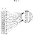
- a related art lenticular type autostereoscopic display apparatus includes a display panel 11, alternately displaying image signals for the left and right eyes, and a lenticular sheet 12, installed in front of the display panel 11, which separates the images for the left and right eyes.
- a time-sharing type autostereoscopic display apparatus that can provide a stereoscopic image without a decrease in the resolution, using a high speed responsive liquid crystal display (LCD) having a refresh rate of 120 Hz.
- LCD liquid crystal display
- Japanese Patent Publication No. 2004-325494 discloses an autostereoscopic display apparatus having a display panel, an image separating unit, and a light deflecting unit.
- the display panel periodically shifts, by a pixel, the left and right images that are alternately displayed.
- a related art image separating unit such as a parallax barrier arranged on the front surface of the display panel separates the left and right images that are alternately displayed by the display panel.
- the light deflecting unit that is periodically shifted in synchronization with the left and right shift period of the display panel deflects an image for the left eye to the left eye and an image for the right eye to the right eye.
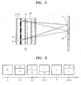
- U.S. Patent No. 5,969,850 discloses an autostereoscopic display apparatus 20 which includes a backlight unit 21, a spatial light modulator 22, a lenticular lens sheet 23, and a high speed responsive LCD display panel 26, as illustrated in FIG. 2 .
- the spatial light modulator 22 is formed of a plurality of left eye and right eye cells 24 and 25 that switch between a transparent state and an opaque state according to the ON/OFF state of power.
- the high speed responsive LCD display panel 26 alternately displays the images for the left eye over the whole screen in a very fast time period.
- the spatial light modulator 22 switches the cells 24 and 25 in synchronization with the left and right image switching time of the high speed responsive LCD display panel 26.
- the spatial light modulator 22 switches the left eye cell 24 to a transparent state so that the light emitted from the backlight unit 21 is directed only towards a left eye viewing zone 28 of a user. Also, while the high speed responsive LCD display panel 26 displays the right eye image, the spatial light modulator 22 turns on the right eye cell 25 so that the light emitted from the backlight unit 21 is directed only towards a right eye viewing zone 27 of the user. In a conventional 2-D mode, all the left eye and right eye cells 24 and 25 of the spatial light modulator 22 are turned on.
- EP 0 788 008 A1 describes the invention relating to a stereoscopic image display apparatus comprising a light source for emitting light from plural apertures, an optical element array composed of an array of optical elements having different optical functions in the horizontal and vertical directions, for giving directivity to the light emerging from the apertures, and a transmissive display device for displaying a stripe image, obtained by dividing each of a parallax image for the right eye and a parallax image for the left eye in the vertical direction to obtain right stripe pixels and left stripe pixels and arranging the right and left stripe pixels alternately in a predetermined order, wherein the plural apertures are provided corresponding to each of the optical elements constituting the optical element array, for each stripe pixel, and are adapted to cause the light, passing through the right or left stripe pixel, to reach a predetermined area.
- a related art autostereoscopic display apparatus can display an image at a scanning speed of about 50-60 Hz or more.
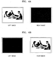
- FIG. 4A at an instant, an image is only viewed by the left eye while no image is viewed by the right eye.
- FIG. 4B at another instant, an image is only viewed by the right eye while no image is viewed by the left eye.
- an autostereoscopic display apparatus has a simple structure and is relatively inexpensive.
- each of the backlight unit and the spatial light modulator is divided into a plurality of segments and each of the segments is operated in synchronization with the vertical scanning time of the LCD panel, cross talk of the left and right images hardly occurs.
- the display panel displays the left and right images by interlacing the left and right images, even when a related art display panel having a relatively slow refresh rate is used, a decrease in the resolution and flickering of the left and right images hardly occurs.
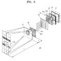
- FIG. 5 is an exploded perspective view schematically illustrating the structure of a high resolution autostereoscopic display apparatus 30 according to an exemplary embodiment of the present invention.
- the high resolution autostereoscopic display apparatus 30 in the present embodiment includes a division type backlight unit 31; a polarizing plate 32 which only transmits light, incident from the backlight unit 31, having a particular polarization direction; a spatial light modulator 33 changing the polarization direction of incident light according to electric control; a first birefringent element array 34 in which a plurality of first and second vertical birefringent elements 34a and 34b, alternately arranged along the horizontal direction, which change the polarization direction of incident light; a lenticular lens sheet 35 separating the incident light into a left eye viewing zone and a right eye viewing zone; a second birefringent element array 36 in which a plurality of third and fourth horizontal birefringent elements 36a and 36b are alternately arranged along the vertical direction; and an LCD panel 37 displaying an image
- the spatial light modulator 33 may be switched between a first status, a second status, and a third status, in which the polarization direction of light passing through the spatial light modulator 33 is different respectively by 45°.
- the spatial light modulator 33 has a first status in which the polarization direction of incident light is not converted, a second status in which the polarization direction of incident light is converted by +45°, and a third status in which the polarization direction of incident light is converted by +90°.
- the conversion angle of the polarization direction in each status of the spatial light modulator 33 is exemplary, the conversion angle can be differently designed according to the polarization directions of the polarizing plate 32 and polarizers of the LCD panel 37.
- the difference between the polarization directions of light is 45° when the spatial light modulator 33 is in each of the first, second, and third statuses.
- the spatial light modulator 33 may be designed such that in the second status, the light is circularly polarized light, not linearly polarized light.
- the spatial light modulator 33 includes an electrically controllable device having three anisotropic states according to the amount of applied voltage.
- a liquid crystal retarder that is formed of an optical compensation bend (OCB) twist nematic liquid crystal panel or a ferro-electric liquid crystal panel and is electrically controllable can be used as the spatial light modulator 33.
- a liquid crystal retarder having a switching speed of about 180 Hz may be available at a relatively low cost.
- the spatial light modulator 33 includes a liquid crystal retarder, for example, the incident light is not delayed in the first status, the incident light is delayed by a phase of 1/4 the wavelength ( ⁇ /4) in the second status, and the incident light is delayed by a phase of 1/2 the wavelength ( ⁇ /2) in the third status.
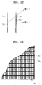
- the first birefringent element array 34 is formed by alternately arranging first and second vertical birefringent elements 34a and 34b along the horizontal direction. That is, the first and second vertical birefringent elements 34a and 34b are respectively formed lengthwise in the longitudinal direction of the autostereoscopic display apparatus 30 and alternately arranged along the horizontal direction.
- the first birefringent element array 34 converts the polarization direction of the incident light such that the polarization directions of light passing through the first and second vertical birefringent elements 34a and 34b are perpendicular to each other.
- each of the first and second vertical birefringent elements 34a and 34b can comprise a polarizer having a polarization plane in a predetermined direction.
- the polarization plane of a polarizer forming the first vertical birefringent element 34a and the polarization plane of a polarizer forming the second vertical birefringent element 34b are perpendicular to each other.
- the first and second vertical birefringent elements 34a and 34b can comprise retarders that delay the incident light by a predetermined phase.
- the retarders forming the first vertical birefringent elements 34a and the retarders forming the second vertical birefringent element 34b are formed such that a phase delay difference therebetween is ⁇ /2.
- the first vertical birefringent element 34a does not delay the phase while the second vertical birefringent element 34b delays the phase by ⁇ /2
- the first vertical birefringent element 34a delays the phase by - ⁇ /4 while the second vertical birefringent element 34b delays the phase by + ⁇ /4.
- the first and second vertical birefringent elements 34a and 34b can comprise rotators that rotate the incident light by a predetermined angle.
- the rotator forming the first vertical birefringent element 34a and the rotator forming the second vertical birefringent element 34b are formed such that a rotation angle difference is 90°.
- the first vertical birefringent element 34a does not rotate the incident light while the second vertical birefringent element 34b rotates the incident light by 90°
- the first vertical birefringent element 34a rotates the incident light by -45° while the second vertical birefringent element 34b rotates the incident light by +45°.
- the light passing through the spatial light modulator 33 and the first birefringent element array 34 may have one of the following polarization directions according to the status of the spatial light modulator 33. That is, first, the polarization direction of light passing through the first vertical birefringent element 34a may be perpendicular to the polarization direction of a polarizer 38a (refer to FIG. 6 ) on the incident side of the LCD panel 37 while the polarization direction of light passing through the second vertical birefringent element 34b is parallel to the polarization direction of the polarizer 38a on the incident side of the LCD panel 37.
- the polarization direction of light passing through the first vertical birefringent element 34a may be parallel to the polarization direction of the polarizer 38a on the incident side of the LCD panel 37 while the polarization direction of light passing through the second vertical birefringent element 34b is perpendicular to the polarization direction of the polarizer 38a on the incident side of the LCD panel 37.
- light passing through the first and second vertical birefringent elements 34a and 34b may be either circularly polarized or linearly polarized and inclined by 45° with respect to the polarization direction of the polarizer 38a on the incident side of the LCD panel 37.
- the lenticular lens sheet 35 includes a plurality of vertical lenticular lens elements that are horizontally arranged.
- each vertical lenticular lens element is formed lengthwise in the vertical direction of the autostereoscopic display apparatus 30, parallel to the first and second vertical birefringent elements 34a and 34b of the first birefringent element array 34.
- the lenticular lens sheet 35 separates the incident light into left and right eye viewing zones. That is, according to the incident position of the incident light, the light passing through the lenticular lens sheet 35 is separated into the left and right eye viewing zones, at a viewing distance, and forms images.
- the light emitted from the first vertical birefringent element 34a can be guided to the left eye viewing zone through the lenticular lens sheet 35 while the light emitted from the second vertical birefringent element 34b can be guided to the right eye viewing zone.
- the interval between the left and right eye viewing zones at a viewing distance may be about 65 mm.
- the pitch between the vertical lenticular lens elements of the lenticular lens sheet 35 may be the same as or less than the pitch between a pair of the first and second vertical birefringent elements 34a and 34b. That is, the width of one vertical lenticular lens element is the same as or slightly less than the sum of the widths of the first and second vertical birefringent elements 34a and 34b. Also, the distance between the lenticular lens sheet 35 and the first birefringent element array 34 is the same as or slightly greater than the focal length of the vertical lenticular lens element.
- the second birefringent element array 36 is arranged in front of the lenticular lens sheet 35.
- the second birefringent element array 36 includes the third and fourth horizontal birefringent elements 36a and 36b that are alternately arranged along the vertical direction of the autostereoscopic display apparatus 30. That is, the third and fourth horizontal birefringent elements 36a and 36b are formed lengthwise in the latitudinal direction of the autostereoscopic display apparatus 30 and alternately arranged along the vertical direction of the autostereoscopic display apparatus 30.
- the second birefringent element array 36 changes the polarization direction of the incident light such that the polarization directions of the light passing through the third and fourth horizontal birefringent elements 36a and 36b are perpendicular to each other.
- each of the third and fourth horizontal birefringent elements 36a and 36b may comprise a polarizer having a polarized plane in a predetermined direction.
- the polarized plane of the polarizer of the third horizontal birefringent element 36a is perpendicular to the polarized plane of the polarizer of the fourth birefringent element 36b.
- the third and fourth horizontal birefringent elements 36a and 36b may be retarders that delay the incident light by a predetermined phase.
- the phase delay difference between the retarder forming the third horizontal birefringent element 36a and the retarder forming the fourth horizontal birefringent element 36b is ⁇ /2.
- the third horizontal birefringent element 36a does not delay the phase of the incident light while the fourth horizontal birefringent element 36b delays the phase of the incident light by ⁇ /2, or the third horizontal birefringent element 36a delays the phase of the incident light by - ⁇ /4 while the fourth horizontal birefringent element 36b delays the phase by + ⁇ /4.
- the third and fourth horizontal birefringent elements 36a and 36b can comprise rotators that rotate the incident light by a predetermined angle.
- the rotator forming the third horizontal birefringent element 36a and the rotator forming the fourth horizontal birefringent element 36b are formed such that a rotation angle difference is 90°.
- the third horizontal birefringent element 36a does not rotate the incident light while the fourth horizontal birefringent element 36b rotates the incident light by 90°
- the third horizontal birefringent element 36a rotates the incident light by -45° while the fourth horizontal birefringent element 36b rotates the incident light by +45°.
- each of the third and fourth horizontal birefringent elements 36a and 36b of the second birefringent element array 36 corresponds to one of the pixel lines of the LCD panel 37.
- the number of third and fourth horizontal birefringent elements 36a and 36b of the second birefringent element array 36 is the same as of the number of pixel lines of the LCD panel 37.
- the third and fourth horizontal birefringent elements 36a and 36b of the second birefringent element array 36 are arranged parallel to the pixel lines of the LCD panel 37.
- the pitch of the third and fourth horizontal birefringent elements 36a and 36b of the second birefringent element array 36 may be slightly greater than that of the pixel lines of the LCD panel 37.
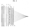
- FIG. 6 is a cross-sectional view for explaining the above relationship that illustrates the vertically crossed section of the autostereoscopic display apparatus 30 of FIG. 5 .
- the third and fourth horizontal birefringent elements 36a and 36b of the second birefringent element array 36 are arranged alternately in the vertical direction in the rear of the LCD panel 37 when viewed by a viewer.
- a plurality of pixels 38c are arranged in 2-dimensions in the vertical and horizontal directions on the LCD panel 37.
- FIG. 6 only the pixels 38c arranged in the vertical direction are illustrated.
- the eye of a viewer is positioned at a certain point in front of the LCD panel 37.
- the third and fourth horizontal birefringent elements 36a and 36b, corresponding to the pixel lines of the LCD panel 37 located higher or lower than the position of the eye of the viewer need to be arranged at positions higher or lower than the corresponding pixel lines as illustrated in FIG. 6 .
- the pitch of the third and fourth horizontal birefringent elements 36a and 36b of the second birefringent element array 36 is slightly greater than the pitch of the pixel lines of the LCD panel 37.
- the pitch of the third and fourth horizontal birefringent elements 36a and 36b of the second birefringent element array 36 is about 0.266 mm.
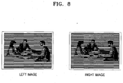
- the LCD panel 37 displays images by interlacing the images for the left and right eyes. For example, in the first frame, the left eye image is displayed on odd pixel lines while the right eye image is displayed on even pixel lines. In the next frame, the right eye image is displayed on the odd pixel lines while the left eye image is displayed on the even pixel lines.
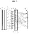
- FIG. 7 is a cross-sectional view illustrating the operation of the autostereoscopic display apparatus 30 of FIG. 5 in which the spatial light modulator 33 is in the first status.
- the polarizers 38a and 38b are attached to the incident side and the exit side of the LCD panel 37.
- the polarizing plate 32 and the polarizer 38a at the incident side of the LCD panel 37 are assumed to have a horizontal polarization direction.
- the spatial light modulator 33 is assumed to be a liquid crystal retarder having a first status in which the polarization direction of the incident light does not change, a second status in which the polarization direction of the incident light changes by 45°, and a third status in which the polarization direction of the incident light changes by 90°.
- first vertical birefringent elements 34a of the first birefringent element array 34 do not delay the phase of light while the second vertical birefringent elements 34b of the first birefringent element array 34 delay the phase of light by half a wavelength ( ⁇ /2).
- the second birefringent element array 36 has third horizontal birefringent elements 36a at the odd rows and fourth horizontal birefringent elements 36b at the even rows.
- the polarization direction of light that passes through the polarizing plate 32 and is incident upon the spatial light modulator 33 does not change.
- the light passing through the spatial light modulator 33 has a horizontal polarization direction.
- the light passing through the first and second vertical birefringent elements 34a and 34b the light passing through the first vertical birefringent element 34a maintains the horizontal polarization direction while the polarization direction of light passing through the second vertical birefringent element 34b changes by 90° so as to have a vertical polarization direction.
- the light passing through the first and second vertical birefringent elements 34a and 34b is separated by the lenticular lens sheet 35 into the left and right eye zones L and R and guided by the lenticular lens sheet 35 towards the left and right eye zones. That is, the light passing through the first vertical birefringent element 34a proceeds towards the left eye zone L of a viewing zone 100 while the light passing through the second vertical birefringent element 34b proceeds towards the right eye zone R of the viewing zone 100.
- the light separated by the lenticular lens sheet 35 passes through the third and fourth horizontal birefringent elements 36a and 36b arranged along the vertical direction.
- the light passing through the third horizontal birefringent element 36a maintains the horizontal polarization direction while the polarization direction of light passing through the fourth horizontal birefringent element 36b changes by 90° so as to have a vertical polarization direction.
- the light passing through the third horizontal birefringent element 36a maintains the vertical polarization direction while the polarization direction of light passing through the fourth horizontal birefringent element 36b changes by 90° so as to have a horizontal polarization direction. That is, of the light proceeding towards the left eye viewing zone L of the viewing zone 100, the light passing through the odd rows of the second birefringent element array 36 has a horizontal polarization direction while the light passing through the even rows of the second birefringent element array 36 has a vertical polarization direction. Also, of the light proceeding towards the right eye viewing zone R of the viewing zone 100, the light passing through the odd rows of the second birefringent element array 36 has a vertical polarization direction while the light passing through the even rows has a horizontal polarization direction.
- the polarizer 38a at the incident side of the LCD panel 37 has a horizontal polarization direction.
- the light passing through the odd rows of the second birefringent element array 36 passes through the polarizer 38a, but the light passing through the even rows of the second birefringent element array 36 does not pass through the polarizer 38a.
- the light passing through the odd rows of the second birefringent element array 36 does not pass through the polarizer 38a at the incident side of the LCD panel 37, but the light passing through the even rows of the second birefringent element array 36 passes through the polarizer 38a at the incident side of the LCD panel 37.
- the third and fourth horizontal birefringent elements 36a and 36b of the second birefringent element array 36 correspond to the pixel lines of the LCD panel 37.
- the image displayed from the odd rows of the pixel lines of the LCD panel 37 proceeds towards the left eye viewing zone L of the viewing zone 100 while the image displayed from the even rows of the pixel lines of the LCD panel 37 proceeds towards the right eye viewing zone R of the viewing zone 100.
- the image of the odd rows of the pixel lines of the LCD panel 37 is recognized by the left eye while the image of the even rows of the pixel lines of the LCD panel 37 is recognized by the right eye.
- FIG. 9 illustrates a cross-sectional view of the operation of the autostereoscopic display apparatus 30 according to the present invention.
- the polarization direction of light passing through the polarizing plate 32 and incident on the spatial light modulator 33 changes by 90°.
- the light passing through the spatial light modulator 33 has a vertical polarization direction.
- the light passing through the first vertical birefringent elements 34a maintains the vertical polarization direction while the polarization direction of light passing through the second vertical birefringent elements 34b changes by 90° so as to have a horizontal polarization direction.
- the light passing through the first and second vertical birefringent elements 34a and 34b are separated into the left and right eye viewing zones by the lenticular lens sheet 35 and guided by the lenticular lens sheet 35 towards the left and right eye viewing zones. That is, the light passing through the first vertical birefringent elements 34a proceeds to the left eye viewing zone L of the viewing zone 100 as directed by the lenticular lens sheet 35 and the light passing through the second vertical birefringent elements 34b proceeds to the right eye viewing zone R of the viewing zone 100 as directed by the lenticular lens sheet 35.
- the light separated by the lenticular lens sheet 35 passes through the third and fourth horizontal birefringent elements 36a and 36b.
- the light passing through the third horizontal birefringent element 36a maintains the vertical polarization direction while the polarization direction of light passing through the fourth horizontal birefringent elements 36b changes by 90° so as to have a horizontal polarization direction.
- the light passing through the third horizontal birefringent elements 36a maintains the horizontal polarization direction while the polarization direction of light passing through the fourth horizontal birefringent elements 36b changes by 90° so as to have a vertical polarization direction. That is, of the light proceeding towards the left eye viewing zone L of the viewing zone 100, the light passing through the odd rows of the second birefringent element array 36 has a vertical polarization direction while the light passing through the even rows of the second birefringent element array 36 has a horizontal polarization direction.
- the light passing through the odd rows of the second birefringent element array 36 has a horizontal polarization direction while the light passing through the even rows of the second birefringent element array 36 has a vertical polarization direction.
- the polarizer 38a at the incident side of the LCD panel 37 has a horizontal polarization direction.
- the light passing through the odd rows of the second birefringent element array 36 does not pass through the polarizer 38a at the incident side of the LCD panel 37, while only the light passing through the even rows of the second birefringent element array 36 can pass through the polarizer 38a at the incident side of the LCD panel 37.
- the light passing through the odd rows of the second birefringent element array 36 can pass through the polarizer 38a at the incident side of the LCD panel 37, but the light passing through the even rows of the second birefr ingent element array 36 cannot pass through the polarizer 38a at the incident side of the LCD panel 37.
- the image displayed from the odd rows of the pixel lines of the LCD panel 37 proceeds towards the right eye viewing zone R of the viewing zone 100 while the image displayed from the even rows of the pixel lines of the LCD panel 37 proceeds towards the left eye viewing zone L of the viewing zone 100.
- the image of the odd pixel lines of the LCD panel 37 is recognized by the right eye while the image of the even pixel lines of the LCD panel 37 is recognized by the left eye.
- the spatial light modulator 33 switches to the first status. In the next frame, while the LCD panel 37 displays the right eye image in the odd pixel lines and the left eye image in the even pixel lines, the spatial light modulator 33 switches to the third status.
- the spatial light modulator 33, the first birefringent element array 34, and the second birefringent element array 36 together control the polarization direction such that the light proceeding towards the left eye viewing zone L of the viewing zone 100 is incident on the pixel lines of the LCD panel 37 where the left eye image is displayed and the light proceeding towards the right eye viewing zone R of the viewing zone 100 is incident on the pixel lines of the LCD panel 37 where the right eye image is displayed.
- the spatial light modulator 33, the first birefringent element array 34, and the second birefringent element array 36 together constitute a single polarization switch.
- an image is displayed by scanning twice, that is, once for odd rows and once for even rows.
- an image can be displayed without decreasing resolution and simultaneously preventing flickering at a relatively slow scanning speed of 25 Hz (PAL) or 30 Hz (NTSC).
- PAL 25 Hz
- NTSC 30 Hz
- the flickering and decrease of resolution are hardly noticeable when the related art LCD panel 37 having a vertical scanning speed, that is, a refresh rate, of 60-75 Hz, is used.
- a 2-dimensional image mode 2D mode
- the spatial light modulator 33 may be repeatedly switched between the first and third statuses so that the LCD panel 37 displays the same 2D image continuously twice.
- the odd rows of the same 2D image are recognized by the left eye and the even rows of the same 2D image are recognized by the right eye.
- the even rows of the same 2D image are recognized by the left eye and the odd rows of the same 2D image are recognized by the right eye.
- a viewer can sense a 2D image.
- the spatial light modulator 33 is maintained in the second status and the LCD panel 37 displays a 2D image frame by frame in a conventional manner.
- the polarization direction of light passing through the polarizing plate 32 and incident on the spatial light modulator 33 changes by 45°.
- the light passing through the spatial light modulator 33 has a polarization direction of 45°, that is, in a diagonal direction.
- the light continuously passes through the first and second vertical birefringent elements 34a and 34b and the third and fourth horizontal birefringent elements 36a and 36b.
- the first through fourth birefringent elements 34a, 34b, 36a, and 36b do not change the polarization direction of the incident light or change the polarization direction of the incident light by 90°.
- the light passes through the LCD panel 37 and forms an image in both of the left and right viewing zones L and R of the viewing zone 100.
- the LCD panel 37 displays a 2D image
- a user can view the 2D image through the left and right eyes.
- the spatial light modulator 33 when the spatial light modulator 33 is in the second status, instead of changing the polarization direction of the incident light by 45°, the polarization state of the incident light can be changed so that the exit light becomes circularly polarized light.
- the spatial light modulator 33 does not change the polarization direction of the incident light in the first status, however, it changes the polarization direction of the incident light by 90° in the third status, and changes the incident light to circularly polarized light in the second status.
- the incident light changes to circularly polarized light in the second status, the same result as the case in which the polarization direction of the incident light changes by 45° can be obtained.
- the autostereoscopic display apparatus 30 uses the backlight unit 31 and the spatial light modulator 33 which are divided into N-segments. That is, the backlight unit 31 and the spatial light modulator 33 are divided into a plurality of horizontal segments that are sequentially switched in synchronization with the vertical scanning time of the LCD panel 37. The horizontal segments of the backlight unit 31 and spatial light modulator 33 can be independently switched and are arranged along the vertical direction.
- the number of horizontal segments of the backlight unit 31 and of the spatial light modulator 33 can be appropriately chosen according to the design.
- a horizontal segment of the backlight unit 31 and of the spatial light modulator 33 may correspond to a pixel line of the LCD panel 37.
- manufacturing costs are high.
- the horizontal segments of each of the backlight unit 31 and of the spatial light modulator 33 may instead correspond to the number of pixel lines of the LCD panel 37.
- a horizontal segment of the backlight unit 31 and a horizontal segment of the spatial light modulator 33 may correspond to 100 pixel lines of the LCD panel 37.
- the number of horizontal segments of the backlight unit 31 may be the same as that of the spatial light modulator 33.
- each horizontal segment of the spatial light modulator 33 for example, switches to the first status when the pixel lines of the LCD panel 37 corresponding thereto display an image of a frame and to the third status when the image of the next frame is displayed.
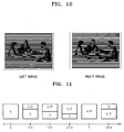
- FIG. 11 illustrates the switching operation of the spatial light modulator 33.
- the spatial light modulator 33 is a four-division spatial light modulator that is divided into four segments and a liquid crystal retarder that does not delay the incident light in the first status and delays the phase of the incident light by 1/2 a wavelength ( ⁇ /2) in the third status. As illustrated in FIG. 11 , the spatial light modulator 33 is entirely in the first status at time "0" and entirely in the third status at time "T". The spatial light modulator 33 continuously changes from the first status to the third status between the time 0 and the time T in synchronization with the LCD panel 37. The switching operation of the spatial light modulator 33 is controlled in order to be accurately synchronized with the time when the LCD panel 37 displays the image of each frame. As a result, cross talk hardly occurs during the time when the images of two frames share the screen and the left eye image and the right eye image can be accurately separated.
- FIG. 12 is a cross-sectional view for explaining the reason for the generation of ⁇ cross talk according to the viewing height of a viewer.
- the third horizontal birefringent element 36a and the fourth horizontal birefringent element 36b accurately correspond to a first pixel Px1 and a second pixel Px2, respectively.
- the viewer views the image at a height H' that is higher than the normal height H, it seems as if the first pixel Px1 corresponds to the fourth horizontal birefringent device 36b.
- the viewer sees an autostereoscopic image in which the left and right images are reversed and at a height between the height H and height H', the viewer sees an image in which the left and right images are not clearly separated.
- a black matrix 38d existing between the pixels 38c of the LCD panel 37 is used.
- the black matrix 38d having a width D2 in the vertical direction is formed between the pixels 38c of the LCD panel 37 in order to separate the pixels 38c of the LCD panel 37.
- an opaque mask 36c having a strip shape corresponding to the black matrix 38d of the LCD panel 37 is horizontally arranged between the third and fourth horizontal birefringent elements 36a and 36b.
- the width of the opaque mask 36c in the vertical direction is indicated by D1.
- the pitch of the second birefringent element array 36 is P1
- the pitch of the pixel 38c of the LCD panel 37 is P2
- the range of height at which the left and right images are clearly separate is H2
- the range of height at which the left and right images are reversed is H1
- the distance between the second birefringent element array 36 and the pixel 38c of the LCD panel 37 is t
- the viewing distance from the pixel 38c of the LCD panel 37 to a viewer is L.
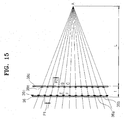
- Equation 1 can be obtained from triangles AEF and ABC in FIG. 15 .
- P 2 / L P 1 / L + t
- Equation 2 can be obtained from trapezoids CEFG, and ABFG and the following Equation 3 can be obtained from trapezoids CEFG and ABCE.
- t / L P 2 + D 2 / H 2 .
- Equation 4 L / t D 1 + D 2 + t / L D 2
- Equation 5 as the widths D1 and D2 of the opaque mask 36c of the second birefringent element array 36 and the black matrix 38d of the LCD panel 37 increase, the range H2 of the height at which the left and right images are clearly separate can be increased.
- the width of the opaque mask 36c is maximized within a range in which reduction of the brightness of a displayed image is minimized. By doing so, the range H2 of a height at which the left and right images are clearly separate can be increased to about 150-200 mm.
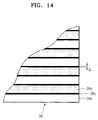
- FIG. 17 illustrates the structure of the viewing zone 100 formed by the autostereoscopic display apparatus 30 according to the present invention. As illustrated in FIG. 17 , in the range H2, a clearly separate autostereoscopic image can be viewed; in the range H1, an area 100a, the left and right images are not clearly separate; and an area 100b the left and right images are reversed.
- FIG. 18 is an exploded perspective view schematically illustrating the structure of a high resolution autostereoscopic display apparatus 40 according to another exemplary embodiment of the present invention.
- the high resolution autostereoscopic display apparatus 40 includes a backlight unit 41, a spatial light modulator 42 that switches between a transparent state and an opaque state according to electric control, a lenticular lens sheet 45 separating the incident light into the left eye viewing zone L and the right eye viewing zone R, and a LCD panel 47 displaying an image.
- the backlight unit 41 does not need to be a division type and a related art backlight unit can be used.
- the division type backlight unit 31 can be used as the backlight unit 41.
- the LCD panel 47 like the embodiment illustrated in FIG. 5 , displays an image according to the interlaced method instead of a time-sharing type method. That is, the LCD panel 37 displays the left and right eye images by interlacing the left and right eye images. For example, in the first frame, the left eye image is displayed in the odd pixel lines and the right eye image is displayed in the even pixel lines. In the next frame, the right eye image is displayed in the odd pixel lines and the left eye image is displayed in the even pixel lines.
- the spatial light modulator 42 includes a plurality of cells that are arranged in two dimensions along rows and columns and are independently controllable.
- the number of rows of the spatial light modulator 42 that is, the number of cells in the vertical direction, may be the same as the number of pixel lines of the LCD panel 47.
- the spatial light modulator 42 can be switched between three statuses. That is, the spatial light modulator 42 switches between the first status in which all cells of the spatial light modulator 42 are transparent, the second status in which the transparent cells and opaque cells are arranged in a checkered pattern, and the third status, which is complementary to the second status, in which the transparent cells in the second status become opaque and the opaque cells in the second status become transparent.
- the spatial light modulator 42 can be switched at a high speed between the second and third statuses sequentially line by line in synchronization with the vertical scanning time of the LCD panel 47.
- the spatial light modulator 42 can use a structure in which, for example, an optical compensation bend (OCB) twist nematic (TN) liquid crystal panel or a ferro-electric liquid crystal (FELC) panel is arranged between two polarizers. Since a polarizer is arranged on the incident surface of the LCD panel 47, the spatial light modulator 42 according to the present embodiment can comprise a polarizer and a liquid crystal panel.
- OBC optical compensation bend
- TN optical compensation bend
- FELC ferro-electric liquid crystal
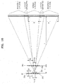
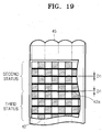
- FIG. 19 illustrates in detail the relative arrangement of the spatial light modulator 42 and the lenticular lens sheet 45 of the high resolution autostereoscopic display apparatus 40 illustrated in FIG. 18 , according to an exemplary embodiment of the present invention.
- the lenticular lens sheet 45 is arranged to face and be parallel to the spatial light modulator 42.
- the lenticular lens sheet 45 is arranged such that a lens element of the lenticular lens sheet 45 corresponds to two columns of the spatial light modulator 42.
- the pitch between the lens elements of the lenticular lens sheet 45 is equal to, or slightly greater than twice pitch between the columns of the spatial light modulator 42.
- the distance t2 between the lenticular lens sheet 45 and the spatial light modulator 42 is the same as or slightly greater than the focal length of the lenticular lens element of the lenticular lens sheet 45.
- cross talk in which the left and right images are mixed or reversed according to the viewing height of a viewer may occur for the same reason as explained above with reference to FIG. 12 .
- an opaque mask 42a having a striped shape and a width D1 is arranged in the horizontal direction between the rows of the respective cells of the spatial light modulator 42.
- the pitch in the vertical direction between the opaque masks 42a in the horizontal direction of the spatial light modulator 42 may be slightly greater than the pitch between the pixel lines of the LCD panel 47.
- the width of the opaque mask 42a of the spatial light modulator 42 is D1
- the width of the black matrix between the pixels of the LCD panel 47 is D2
- the distance between the black matrix of the LCD panel 47 and the opaque mask 42a of the spatial light modulator 42 is t1
- the viewing distance from the LCD panel 47 is L
- the distance t1 between the black matrix and the opaque mask 42a can be a sum of the optical thicknesses (i.e. physical thickness/ refractive index) of a substrate of the spatial light modulator 42, a substrate of the LCD panel 47, and the lenticular lens sheet 45.
- the thickness of the substrate of the spatial light modulator 42 is 0.7 mm
- the thickness of the lenticular lens sheet 45 is 0.2 mm
- the thickness of the substrate of the LCD panel 47 is 0.7 mm
- the thickness of the polarizer is 0.2 mm
- the average refractive index n of the above devices is 1.5
- the width of the opaque mask 42a D1 is 0.1 mm
- the width D2 of the black matrix is 0.05 mm
- the viewing distance L from the LCD panel 47 is 700 mm
- each lens element of the lenticular lens sheet 45 corresponds to two columns of the spatial light modulator 42.
- the light passing through the odd columns of the spatial light modulator 42 is always deflected to the right and proceeds towards the left eye of the viewer.
- the light passing through the even columns of the spatial light modulator 42 is always deflected to the left by the lenticular lens sheet 45 and proceeds towards the right eye of the viewer.
- the spatial light modulator 42 when the spatial light modulator 42 is in the second status and viewing in the direction in which the light proceeds, it is assumed that in the odd rows of the spatial light modulator 42, the odd columns of the spatial light modulator 42 are transparent and the even columns of the spatial light modulator 42 are opaque and, in the even rows of the spatial light modulator 42, the odd columns of the spatial light modulator 42 are opaque and the even columns of the spatial light modulator 42 are transparent (see the upper portion of the spatial light modulator 42 of FIG. 19 ). In this case, since only the odd columns of the spatial light modulator 42 transmit light in the odd rows of the spatial light modulator 42, the light passing through the odd rows of the spatial light modulator 42 proceeds towards the left eye of the viewer.
- the even columns of the spatial light modulator 42 transmit the light in the even rows of the spatial light modulator 42
- the light passing through the even rows of the spatial light modulator 42 proceeds towards the right eye of the viewer.
- a portion of the LCD panel 47 corresponding to a portion in the second status of the spatial light modulator 42 displays the left eye image in the odd pixel lines and the right eye image in the even pixel lines.
- the spatial light modulator 42 when the spatial light modulator 42 is in the third status and viewed from the direction in which the light proceeds, it is assumed that in the odd rows of the spatial light modulator 42, the odd columns of the spatial light modulator 42 are opaque and the even columns of the spatial light modulator 42 are transparent and in the even rows of the spatial light modulator 42, the odd columns of the spatial light modulator 42 are transparent and the even columns of the spatial light modulator 42 are opaque (see the lower portion of the spatial light modulator 42 of FIG. 19 ). In this case, since only the even columns of the spatial light modulator 42 transmit light in the odd rows of the spatial light modulator 42, the light passing through the odd rows of the spatial light modulator 42 proceeds towards the right eye of the viewer.
- the LCD panel 47 corresponding to a portion in the third status of the spatial light modulator 42 displays the right eye image in the odd pixel lines and the left eye image in the even pixel lines.
- the spatial light modulator 42 switches to the second status when the LCD panel 47 displays the first frame and to the third status when the LCD panel 47 displays the second frame.
- the spatial light modulator 42 since the spatial light modulator 42 according to the present embodiment switches between the second and third statuses sequentially line by line in synchronization with the vertical scanning time of the LCD panel 47, cross talk does not occur during when the LCD panel 47 displays the first and second frames at the same time. Also, since the LCD panel 47 displays the image according to the interlaced method, the decrease in the resolution and the generation of flickering can be minimized.
- the 2-dimensional image mode (2D mode) can be embodied in a number of ways.
- the spatial light modulator 42 switches between the second and third statuses and the LCD panel 47 and continuously displays the same 2D image twice. Then, the odd rows of the same 2D image are recognized by the left eye and the even rows of the same 2D image are recognized by the right eye. Next, the even rows of the same 2D image are recognized by the left eye and the odd rows of the same 2D image are recognized by the right eye.
- a viewer can sense a 2D image.
- the spatial light modulator 42 while the spatial light modulator 42 is maintained in the first status in which all cells are transparent, the LCD panel 47 displays a 2D image in a conventional method.
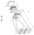
- FIG. 20 is an exploded perspective view schematically illustrating the structure of a high resolution autostereoscopic display apparatus 50 according to another exemplary embodiment of the present invention.
- the high resolution autostereoscopic display apparatus 50 includes a backlight unit 51, a polarizing plate 52 transmitting light having a particular polarization direction of light emitted from the backlight unit 51, a spatial light modulator 53 changing the polarization direction of incident light according to electric control, a lenticular lens sheet 55 separating the incident light into the left eye viewing zone L and the right eye viewing zone R, a birefringent element array 56 in which a plurality of first and second horizontal birefringent elements 56a and 56b are alternately arranged in the vertical direction, and an LCD panel 57 displaying an image.
- the backlight unit 51 does not need to be a division type and a related art backlight unit can be used. However, like the embodiment illustrated in FIG. 5 , a division type backlight unit 51 can be used.
- the LCD panel 57 displays an image according to the interlaced method instead of the time-sharing type method. That is, the LCD panel 57 displays the left and right eye images by interlacing the left and right eye images. For example, in the first frame, the left eye image is displayed from the odd pixel lines and the right eye image is displayed from the even pixel lines. In the next frame, the right eye image is displayed from the odd pixel lines and the left eye image is displayed from the even pixel lines.
- the spatial light modulator 53 includes a plurality of vertical columns that are independently controllable. According to the present embodiment, the spatial light modulator 53 can switch between two statuses. That is, the spatial light modulator 53 switches between the first status in which the odd vertical columns (hereinafter, referred to as the odd columns) do not change the polarization direction of the incident light and the even vertical columns (hereinafter, referred to as the even columns) change the polarization direction of the incident light by +90° or -90° and the second status in which the odd columns change the polarization direction of the incident light by +90° or -90° and the even columns do not change the polarization direction of the incident light.
- the first status in which the odd vertical columns (hereinafter, referred to as the odd columns) do not change the polarization direction of the incident light
- the even vertical columns hereinafter, referred to as the even columns
- the second status in which the odd columns change the polarization direction of the incident light by +90° or -90° and the even columns
- the odd columns of the spatial light modulator 53 do not delay a phase of light while the even columns delay a phase of light by +1/2 wavelength, or by -1/2 wavelength.
- the odd columns delay a phase of light by +1/2 wavelength, or by -1/2 wavelength while the even columns of the spatial light modulator 53 do not delay the phase of light.
- the spatial light modulator 53 can be switched at a high speed between the first and second statuses sequentially line by line in synchronization with the vertical scanning time of the LCD panel 57.
- FIG. 22 illustrates in detail the structure of the spatial light modulator 53 of the high resolution autostereoscopic display apparatus 50 illustrated in FIG. 20 , according to an exemplary embodiment of the present invention.
- the spatial light modulator 53 may be a liquid crystal panel including a liquid crystal layer 53a of an OCB TN type or FELC type, an even column electrode 53b and an odd column electrode 53c arranged in the vertical direction on the front surface of the liquid crystal layer 53a in an inter-digit method, and a common electrode 53d arranged on the rear surface of the liquid crystal layer 53a.
- the even column electrode 53b and odd column electrode 53c are electrically independent from each other.
- the spatial light modulator 53 is driven such that a voltage is not applied to the odd column electrode 53c while the voltage is applied to the even column electrode 53b, or contrarily the voltage is not applied to the even column electrode 53d while the voltage is applied to the odd column electrode 53c.
- the common electrode 53d is divided into a plurality of horizontal segments so that the spatial light modulator 53 is sequentially switched in synchronization with the vertical scanning time of the LCD panel 57.
- the horizontal segments of the common electrode 53d may be electrically independent of one another.
- the driving voltage can be sequentially applied to each of the horizontal segments of the common electrode 53d according to the vertical scanning time of the LCD panel 57.
- the spatial light modulator 53 can be operated by including the separate plurality of horizontal segments, for example, the spatial light modulator 53 switches such that the upper portion of the spatial light modulator 53 can switch to the first status and the lower portion of the spatial light modulator 53 can switch to the second status.
- the lenticular lens sheet 55 faces the spatial light modulator 53 and is parallel to the spatial light modulator 53.
- the lenticular lens sheet 55 is arranged such that each lens element of the lenticular lens sheet 55 corresponds to two columns of the spatial light modulator 53.
- the pitch between the lens elements of the lenticular lens sheet 44 is the same as or slightly less than twice of the pitch of the columns of the spatial light modulator 53. That is, the width of one vertical lenticular lens element is the same as or slightly less than the width of two columns of the spatial light modulator 53.
- the distance between the lenticular lens sheet 55 and the spatial light modulator 53 is the same as or slightly greater than the focal length of the vertical lenticular lens element.
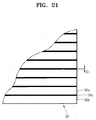
- FIG. 21 schematically illustrates the structure of the birefringent element array 56 of the high resolution autostereoscopic display apparatus 50 illustrated in FIG. 20 , according to an exemplary embodiment of the present invention.
- the birefringent element array 56 includes the plurality of first and second horizontal birefringent elements 56a and 56b that are alternately arranged in the vertical direction.
- the first and second birefringent elements 56a and 56b are formed to change the polarization direction of the incident light such that the polarization directions of light passing through the first and second birefringent elements 56a and 56b are perpendicular to each other.
- the first birefringent elements 56a do not delay a phase of the light and the second birefringent elements 56b may be retarders that delay the phase of the light by -1/2 wavelength or by +1/2 wavelength.
- the birefringent element array 56 further includes an opaque mask 56c in a striped shape having a width D1 and arranged in the horizontal direction between the first and second birefringent elements 56a and 56b.
- the first and second birefringent elements 56a and 56b of the birefringent element array 56 correspond to the pixel lines of the LCD panel 57.
- the number of first and second birefringent elements 56a and 56b of the birefringent element array 56 is the same as that of the pixel lines of the LCD panel 57.
- the pitch of the first and second birefringent elements 56a and 56b of the birefringent element array 56 may be slightly greater than that of the pixel lines of the LCD panel 57.
- the birefringent element array 56 can be a thin film type.
- the birefringent element array 56 of a film type can be directly attached to the polarizer at the incident side of the LCD panel 57.
- the distance t between the black matrix in the LCD panel 57 and the opaque mask 56c of the birefringent element array 56 is very short. Then, the height H2 of the viewing zone having no cross talk can be greatly increased.
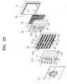
- FIG. 23 shows the operation of the autostereoscopic display apparatus 50 illustrated in FIG. 20 , according to an exemplary embodiment of the present invention.
- the polarizing plate 52 has a polarization direction of 45° and a polarizer 57a at the incident side of the LCD panel 57 has a polarization direction of 135°.
- the upper portion of the LCD panel 57 displays the left eye image in the odd pixel liens and the right eye image in the even pixel lines.
- the lower portion of the LCD panel 57 displays the right eye image in the odd pixel lines and the left eye image in the even pixel lines.
- the upper portion of the spatial light modulator 53 is in the second status in which the odd columns change the polarization direction of the incident light by +90° and the even columns do not change the polarization direction of the incident light, when viewed in the direction in which the light proceeds.
- the lower portion of the spatial light modulator 53 is in the first status in which the even columns change the polarization direction of the incident light by +90° and the odd columns dodoes not change the polarization direction of the incident light. It is assumed that the first birefringent elements 56a of the birefringent element array 56 do not change the polarization direction of the incident light and the second birefringent elements 56b change the polarization direction of the incident light by +90°.
- the light proceeding towards the upper portion of the LCD panel 57 will be described.
- the light emitted from the backlight unit 51 proceeds to the polarizing plate 52 in order to have a polarization direction of 45°. Since the upper portion of the spatial light modulator 53 is in the second status when viewed in the direction in which the light proceeds, the light passing through the odd columns of the upper portion of the spatial light modulator 53 has a polarization direction of 135° and the light passing through the even columns of the upper portion of the spatial light modulator 53 has a polarization direction of 45°.
- each lens element of the lenticular lens sheet 55 corresponds to two columns of the spatial light modulator 53
- the light passing through the odd columns of the spatial light modulator 53 is always deflected to the right by the lenticular lens sheet 55 in order to proceed towards the left eye of the viewer.
- the light passing through the even columns of the spatial light modulator 53 is always deflected to the left by the lenticular lens sheet 55 in order to proceed towards the right eye of the viewer.
- the light passing through the lenticular lens sheet 55 and proceeding towards the left eye of the viewer has a polarization direction of 135° and the light proceeding towards the right eye of the viewer has a polarization direction of 45°.
- the first birefringent elements 56a of the birefringent element array 56 allow the light to pass as the light is, the light passing through the first birefringent elements 56a of the birefringent element array 56 and proceeding towards the left eye of the viewer has a polarization direction of 135° and the light proceeding towards the right eye of the viewer has a polarization direction of 45°.
- the second birefringent elements 56b of the birefringent element array 56 change the polarization direction of the incident light by +90°, the light passing through the second birefringent elements 56b of the birefringent element array 56 and proceeding towards the left eye of the viewer has a polarization direction of 45° and the light proceeding towards the right eye of the viewer has a polarization direction of 135°.
- the light passing through the birefringent element array 56 is incident on the polarizer 57a at the incident side of the LCD panel 57.
- the polarizer 57a at the incident side of the LCD panel 57 has a polarization direction of 135°, only the light passing through the first birefringent elements 56a of the birefringent element array 56 and proceeding towards the left eye of the viewer can pass through the polarizer 57a.
- the light passing through the second birefringent device 56b of the LCD panel 57 the light proceeding towards the right eye of the viewer can only pass through the polarizer 57a.
- the light proceeding towards the left eye of the viewer is incident on the odd pixel lines of the LCD panel 57 and the light proceeding towards the right eye of the viewer is incident on the even pixel lines of the LCD panel 57.
- the upper portion of the LCD panel 57 displays the left eye image in the odd pixel lines and the right eye image in the even pixel lines.
- the left eye image can proceed towards the left eye of the viewer and the right eye image proceeds towards the right eye of the viewer.
- the above description describes the light proceeding towards the upper portion of the LCD panel 57.
- the light proceeding towards the lower portion of the LCD panel 57 can be described with the same principles as described above.
- the light passing through the odd columns of the lower portion of the spatial light modulator 53 has a polarization direction of 45° and the light passing through the even columns of the spatial light modulator 53 has a polarization direction of 135°.
- the light proceeding towards the left eye of the viewer is incident on the even pixel lines of the LCD panel 57 and the light proceeding towards the right eye of the viewer is incident on the odd pixel lines of the LCD panel 57.
- the lower portion of the LCD panel 57 displays the right eye image in the odd pixel lines and the left eye image in the even pixel lines.
- the left eye image can proceed towards the left eye of the viewer and the right eye image proceeds towards the right eye of the viewer.
- the spatial light modulator 53 and the birefringent element array 56 together control the light proceeding towards the left eye viewing zone to be incident on the pixel lines of the display panel 57 displaying the left eye image and the light proceeding towards the right eye viewing zone to be incident on the pixel lines of the display panel 57 displaying the right eye image.
- the spatial light modulator 33 and the birefringent element array 56 together constitute a polarization switch.
Landscapes
- Engineering & Computer Science (AREA)
- Multimedia (AREA)
- Signal Processing (AREA)
- Testing, Inspecting, Measuring Of Stereoscopic Televisions And Televisions (AREA)
Claims (26)
- Autostereoskopische Anzeigevorrichtung (30), umfassend:eine Hintergrundbeleuchtungseinheit (31);eine vor der Hintergrundbeleuchtungseinheit (31) angeordnete Polarisierungsplatte (32);einen zwischen der Polarisierungsplatte (32) und einem lentikularen Linsenblatt (35) angeordneten räumlichen Lichtmodulator (33), der zwischen einem ersten, zweiten und dritten Status umschaltet, worin sich die Polarisationsrichtung von einfallendem Licht gemäß elektrischer Steuerung ändert, dem ersten Status, worin die Polarisationsrichtung des einfallenden Lichts nicht geändert wird, dem zweiten Status, worin der Polarisationszustand des einfallenden Lichts in zirkular polarisiertes Licht umgeändert wird, und dem dritten Status, worin die Polarisationsrichtung des einfallenden Lichts um 90° geändert wird;ein zwischen dem räumlichen Lichtmodulator (33) und dem lentikularen Linsenblatt (35) angeordnetes erstes Doppelbrechungselementarray (34) mit mehreren ersten und zweiten Vertikal-Doppelbrechungselementen (34a, 34b), die sich in der horizontalen Richtung abwechseln und die die Polarisationsrichtung von einfallendem Licht so ändern, dass die Polarisationsrichtung von die ersten Doppelbrechungselemente (34a) durchlaufendem Licht senkrecht zu der Polarisationsrichtung von durch die zweiten Doppelbrechungselemente (34b) verlaufendem Licht ist;das zwischen der Polarisationsplatte (32) und einem Anzeigepanel (37) angeordnete lentikulare Linsenblatt (34), das von der Hintergrundbeleuchtungseinheit (31) emittiertes Licht in eine Links-Augensichtzone (L) und eine Rechts-Augensichtzone (R) auftrennt und dergestalt angeordnet ist, dass Licht, das durch die ersten Doppelbrechungselemente (34a) verläuft, durch das lentikulare Linsenblatt (35) verläuft, um in Richtung der ersten Augensichtzone voranzuschreiten, und Licht, das durch die zweiten Doppelbrechungselemente (34b) verläuft, durch das lentikulare Linsenblatt (35) verläuft, um in Richtung der zweiten Augensichtzone voranzuschreiten;ein zwischen dem lentikularen Linsenblatt (35) und dem Anzeigepanel (37) angeordnetes zweites Doppelbrechungselementarray (36) mit mehreren dritten und vierten Horizontal-Doppelbrechungselementen (36a, 36b), die sich in der vertikalen Richtung abwechseln und die die Polarisationsrichtung von einfallendem Licht so ändern, dass die Polarisationsrichtung von Licht, das durch die dritten Doppelbrechungselemente (36a) verläuft, senkrecht zu der Polarisationsrichtung von Licht ist, das durch die vierten Doppelbrechungselemente (36b) verläuft;einen Polarisierer (38a) an einer Einfallsseite eines Anzeigepanels (37), wobei der Polarisierer (38a) eine Polarisationsrichtung parallel zu einer der Polarisationsrichtungen aufweist, die von einem der dritten oder vierten Doppelbrechungselemente (36a, 36b) ausgegeben werden, unddas Anzeigepanel (37), das dafür ausgelegt ist, ein Links-Augenbild und ein Rechts-Augenbild anzuzeigen, indem Horizontal-Pixelleitungen des Links- und Rechts-Augenbildes sequenziell auf abwechselnden Pixelzeilen des Anzeigepanels (37) verschachtelt werden, wodurch das Anzeigepanel (37) wiederholt ein Bild für eine erste Augensichtzone eines ersten Teilbildes in ungeraden Pixelzeilen und ein Bild für eine zweite Augensichtzone des ersten Teilbildes in geraden Pixelzeilen anzeigt und ein Bild für die erste Augensichtzone eines zweiten Teilbildes in den geraden Pixelzeilen und ein Bild für die zweite Augensichtzone des zweiten Teilbildes in den ungeraden Pixelzeilen anzeigt,wobei die Hintergrundbeleuchtungseinheit (31) und der räumliche Lichtmodulator (33) jeweils in mehrere horizontale Segmente aufgeteilt sind, die sequenziell synchron mit einer Vertikalabtastzeit des Anzeigepanels (37) geschaltet werden, wobei in jedem horizontalen Segment des räumlichen Lichtmodulators (33) der erste und dritte Status des räumlichen Lichtmodulators (33) zeitsequenziell und abwechselnd synchron mit dem Anzeigepanel (37) geschaltet werden,wodurch das in Richtung der Links-Augensichtzone (L) voranschreitende Licht auf die Pixelzeilen des Anzeigepanels (37) einfällt, die das Links-Augenbild anzeigen, und das in Richtung der Rechts-Augensichtzone (R) voranschreitende Licht auf die Pixelzeilen des Anzeigepanels (37) einfällt, die das Rechts-Augenbild anzeigen.
- Vorrichtung nach Anspruch 1, wobei die dritten und vierten Doppelbrechungselemente (36a, 36b) des zweiten Doppelbrechungselementarrays (36) jeweils einer der Pixelleitungen des Anzeigepanels (37) entsprechen.
- Vorrichtung nach Anspruch 1, wobei das zweite Doppelbrechungselementarray (36) ferner eine opake Maske (36c) umfasst, die eine gestreifte Form aufweist, die zwischen den dritten und vierten Doppelbrechungselementen (36a, 36b) angeordnet ist.
- Vorrichtung nach Anspruch 3, die ferner eine zwischen Pixeln des Anzeigepanels (37) angeordnete Schwarzmatrix (38d) umfasst, wobei eine Breite der Schwarzmatrix (38d) D2 ist, eine Breite der opaken Maske (36c) D1 ist, ein Abstand zwischen den Pixeln (38c) des Anzeigepanels (37) und dem zweiten Doppelbrechungselementarray (36) t ist, ein Sichtabstand von dem Anzeigepanel (37) L ist und eine Höhe H2 einer Sichtzone, die kein Übersprechen aufweist, eine Gleichung erfüllt, mit

- Vorrichtung nach Anspruch 1, wobei ein Rasterabstand in einer vertikalen Richtung zwischen den dritten und vierten Doppelbrechungselementen (36a, 36b) des zweiten Doppelbrechungselementarrays (36) größer als ein Rasterabstand in der vertikalen Richtung zwischen Pixelleitungen des Anzeigepanels (37) ist.
- Vorrichtung nach Anspruch 1, wobei jedes der ersten, zweiten, dritten und vierten Doppelbrechungselemente (34a, 34b, 36a, 36b) einen Polarisierer umfasst, der eine vorbestimmte Polarisationsebene aufweist, so dass die Polarisationsebene der Polarisierer der ersten Doppelbrechungselemente (34a) senkrecht zu der Polarisationsebene der Polarisierer der zweiten Doppelbrechungselemente (34b) ist und die Polarisationsebene der Polarisierer der dritten Doppelbrechungselemente (36a) senkrecht zu der Polarisationsebene der Polarisierer der vierten Doppelbrechungselemente (36b) ist.
- Vorrichtung nach Anspruch 1, wobei jedes der ersten, zweiten, dritten und vierten Doppelbrechungselemente (34a, 34b, 36a, 36b) eine Retardierer umfasst, der das einfallende Licht um eine vorbestimmte Phase verzögert, wobei eine Phasenverzögerungsdifferenz zwischen den Retardierern der ersten und zweiten Doppelbrechungselemente (34a, 34b) [lambda]/2 ist und eine Phasenverzögerungsdifferenz zwischen den Retardierern der dritten und vierten Doppelbrechungselemente (36a, 36b) [lambda]/2 ist.
- Vorrichtung nach Anspruch 1, wobei jedes der ersten, zweiten, dritten und vierten Doppelbrechungselemente (34a, 34b, 36a, 36b) einen Dreher umfasst, der das einfallende Licht um einen vorbestimmten Winkel dreht, wobei eine Drehwinkeldifferenz zwischen den Drehern der ersten und zweiten Doppelbrechungselemente (34a, 34b) 90° ist und eine Drehwinkeldifferenz zwischen den Drehern der dritten und vierten Doppelbrechungselemente (36a, 36b) 90° ist.
- Vorrichtung nach Anspruch 1, wobei der räumliche Lichtmodulator (33) ein Flüssigkristallretardierer ist, der elektrisch steuerbar ist.
- Vorrichtung nach Anspruch 1, wobei, wenn sich der räumliche Lichtmodulator (33) in dem ersten Status befindet, Licht, dass die dritten Doppelbrechungselemente (36a) durchläuft, in Richtung der ersten Augensichtzone voranschreitet und Licht, dass durch die vierten Doppelbrechungselemente (36b) verläuft, in Richtung der zweiten Augensichtzone voranschreitet.
- Vorrichtung nach Anspruch 10, wobei, wenn sich der räumliche Lichtmodulator (33) in dem dritten Status befindet, Licht, dass die dritten Doppelbrechungselemente (36a) durchläuft, in Richtung der zweiten Augensichtzone voranschreitet und Licht, dass durch die vierten Doppelbrechungselemente (36b) verläuft, in Richtung der ersten Augensichtzone voranschreitet.
- Vorrichtung nach Anspruch 1, wobei das lentikulare Linsenblatt (35) mehrere vertikale lentikulare Linsenelemente umfasst, die entlang der horizontalen Richtung und parallel zu den ersten und zweiten Doppelbrechungselementen (34a, 34b) des ersten Doppelbrechungselementarrays (34) angeordnet sind.
- Vorrichtung nach Anspruch 12, wobei ein Rasterabstand zwischen den vertikalen lentikularen Linsenelementen des lentikularen Linsenblatts (35) nicht größer als ein Rasterabstand zwischen Paaren der ersten und zweiten Doppelbrechungselemente (34a, 34b) des ersten Doppelbrechungselementarrays (34) ist.
- Vorrichtung nach Anspruch 12, wobei ein Abstand zwischen dem lentikularen Linsenblatt (35) und dem ersten Doppelbrechungselementarray (34) nicht kleiner als eine Brennweite der vertikalen lentikularen Linsenelemente ist.
- Vorrichtung nach Anspruch 1, wobei die Hintergrundbeleuchtungseinheit (31) und der räumliche Lichtmodulator (33) so aufgeteilt sind, dass mehrere horizontale Segmente, die unabhängig geschaltet werden können, entlang der vertikalen Richtung angeordnet sind und die Anzahl der horizontalen Segmente der Hintergrundbeleuchtungseinheit (31) dieselbe wie die Anzahl horizontaler Segmente des räumlichen Lichtmodulators (33) ist.
- Vorrichtung nach Anspruch 15, wobei entsprechende horizontale Segmente der Hintergrundbeleuchtungseinheit (31) und des räumlichen Lichtmodulators (33) simultan geschaltet werden.
- Vorrichtung nach Anspruch 1, wobei die horizontalen Segmente jeweils der Hintergrundbeleuchtungseinheit (31) und des räumlichen Lichtmodulators (33) mehreren Pixelleitungen des Anzeigepanels (37) entsprechen.
- Autostereoskopische Anzeigevorrichtung (50), umfassend:eine Hintergrundbeleuchtungseinheit (51);eine vor der Hintergrundbeleuchtungseinheit (51) angeordnete Polarisierungsplatte (52);einen zwischen der Polarisierungsplatte (52) und dem lentikularen Linsenblatt (55) angeordneten räumlichen Lichtmodulator mit mehreren ersten vertikalen Spalten und zweiten vertikalen Spalten, die abwechselnd bereitgestellt sind, wobei der räumliche Lichtmodulator (53) ausgelegt ist zum Schalten zwischen einem ersten Status, worin die ersten vertikalen Spalten eine Polarisation von einfallendem Licht nicht ändern und die zweiten vertikalen Spalten eine Polarisationsrichtung von einfallendem Licht um +90° oder -90° ändern; und einem zweiten Status, worin die ersten vertikalen Spalten eine Polarisationsrichtung von einfallendem Licht um +90° oder -90° ändern und die zweiten vertikalen Spalten eine Polarisationsrichtung von einfallendem Licht nicht ändern, wobei die ersten vertikalen Spalten des räumlichen Lichtmodulators dadurch aufgereiht werden, um einfallendes Licht durch das lentikulare Linsenblatt (55) in Richtung einer einer ersten oder zweiten Augensichtzone abzulenken, während die zweiten vertikalen Spalten des räumlichen Lichtmodulators aufgereiht sind, um einfallendes Licht durch das lentikulare Linsenblatt (55) in Richtung der anderen der ersten und zweiten Augensichtzone abzulenken;das zwischen der Polarisierungsplatte (52) und einem Anzeigepanel (57) angeordnete lentikulare Linsenblatt (55), das von der Hintergrundbeleuchtungseinheit (51) emittiertes Licht in eine Links-Augensichtzone (L) und eine Rechts-Augensichtzone (R) auftrennt;ein zwischen dem lentikularen Linsenblatt (55) und dem Anzeigepanel (57) angeordnetes Doppelbrechungselementarray (56) mit mehreren ersten und zweiten Horizontal-Doppelbrechungselementen (56a, 56b), die sich in der vertikalen Richtung abwechseln, wobei die ersten Horizontal-Doppelbrechungselemente (56a), die Polarisationsrichtung von einfallendem Licht aufrechterhalten, während die zweiten Doppelbrechungselemente (566) die Polarisationsrichtung von einfallendem Licht so ändern, dass eine Polarisationsrichtung von Licht, das durch die ersten Doppelbrechungselemente (56a) verläuft, senkrecht zu einer Polarisationsrichtung von Licht ist, das durch die zweiten Doppelbrechungselemente (56b) verläuft;einen Polarisierer (57a) an einer Einfallsseite des Anzeigepanels (57), wobei der Polarisierer (57a) eine Polarisationsrichtung parallel zu einer der von einem der ersten oder zweiten Doppelbrechungselemente (56a, 56b) ausgegebenen Polarisationsrichtungen aufweist, unddas Anzeigepanel (57), das ausgelegt ist zum Anzeigen eines Links-Augenbildes und eines Rechts-Augenbildes durch sequenzielles Verschachteln von Horizontal-Pixelleitungen des Links- und Rechts-Augenbildes auf abwechselnden Pixelzeilen des Anzeigepanels (57), wodurch das Anzeigepanel (57) wiederholt ein Bild für eine erste Augensichtzone eines ersten Teilbildes in ungeraden Pixelzeilen und ein Bild für eine zweite Augensichtzone des ersten Teilbildes in geraden Pixelzeilen anzeigt und ein Bild für die erste Augensichtzone eines zweiten Teilbildes in den geraden Pixelzeilen und ein Bild für die zweite Augensichtzone des zweiten Teilbildes in den ungeraden Pixelzeilen anzeigt,wobei der räumliche Lichtmodulator (53) mehrere horizontale Segmente umfasst, die sequenziell synchron mit einer Vertikal-Abtastzeit des Anzeigepanels (57) geschaltet werden,wodurch das in Richtung der Links-Augensichtzone (L) voranschreitende Licht auf die Pixelzeilen des Anzeigepanels (57) einfällt, die das Links-Augenbild anzeigen, und das in Richtung der Rechts-Augensichtzone (R) voranschreitende Licht auf die Pixelzeilen des Anzeigepanels (57) einfällt, die das Rechts-Augenbild anzeigen.
- Vorrichtung nach Anspruch 18, wobei die ersten und zweiten Horizontal-Doppelbrechungselemente (56a, 56b) des Doppelbrechungselementarrays (56) jeweils einer der Pixelleitungen des Anzeigepanels (57) entsprechen.
- Vorrichtung nach Anspruch 18, wobei das Doppelbrechungselementarray (56) ferner eine opake Maske (56c) umfasst, die eine gestreifte Form aufweist, die zwischen den ersten und zweiten Horizontal-Doppelbrechungselementen (56a, 56b) angeordnet ist.
- Vorrichtung nach Anspruch 18, wobei ein Rasterabstand in der vertikalen Richtung zwischen den ersten und zweiten Horizontal-Doppelbrechungselementen (56a, 56b) des Doppelbrechungselementarrays (56) größer als ein Rasterabstand in der vertikalen Richtung zwischen den Pixelleitungen des Anzeigepanels (57) ist.
- Vorrichtung nach Anspruch 18, wobei die ersten und zweiten Horizontal-Doppelbrechungselemente (56a, 56b) jeweils einen Retardierer umfassen, der die Phase des einfallenden Lichts verzögert, wobei eine Phasenverzögerungsdifferenz der Retardierer der ersten Horizontal-Doppelbrechungselemente (56a) und der Retardierer der zweiten Horizontal-Doppelbrechungselemente (56b) [lambda]/2 ist.
- Vorrichtung nach Anspruch 18, wobei das lentikulare Linsenblatt (55) mehrere vertikale lentikulare Linsenelemente umfasst, die entlang der horizontalen Richtung und parallel zu den vertikalen Spalten des räumlichen Lichtmodulators (53) angeordnet sind.
- Vorrichtung nach Anspruch 23, wobei ein Rasterabstand zwischen den vertikalen lentikularen Linsenelementen des lentikularen Linsenblatts (55) nicht größer als zweimal ein Rasterabstand zwischen den vertikalen Spalten des räumlichen Lichtmodulators (53) ist.
- Vorrichtung nach Anspruch 23, wobei ein Abstand zwischen dem lentikularen Linsenblatt (55) und dem räumlichen Lichtmodulator (53) nicht kleiner als eine Brennweite des vertikalen lentikularen Linsenelements ist.
- Vorrichtung nach Anspruch 18, wobei der räumliche Lichtmodulator (53) Folgendes umfasst:eine Flüssigkristallschicht (53a);erste und zweite Vertikal-Spaltenelektroden (53c, 53b), die in der vertikalen Richtung auf einer vorderen Oberfläche der Flüssigkristallschicht (53a) einander in einem verschränkten Array zugewandt angeordnet sind; undeine gemeinsame Elektrode (53d), die auf einer hinteren Oberfläche der Flüssigkristallschicht (53a) angeordnet ist, wobei die gemeinsame Elektrode (53d) mehrere horizontale Segmente umfasst.
Applications Claiming Priority (3)
| Application Number | Priority Date | Filing Date | Title |
|---|---|---|---|
| US79737306P | 2006-05-04 | 2006-05-04 | |
| KR1020060067301A KR101255209B1 (ko) | 2006-05-04 | 2006-07-19 | 인터레이스 방식으로 영상을 디스플레이 하는 고해상도입체 영상 디스플레이 장치 |
| PCT/KR2007/001884 WO2007129816A1 (en) | 2006-05-04 | 2007-04-18 | High resolution autostereoscopic display apparatus with interlaced image |
Publications (3)
| Publication Number | Publication Date |
|---|---|
| EP2014104A1 EP2014104A1 (de) | 2009-01-14 |
| EP2014104A4 EP2014104A4 (de) | 2012-01-25 |
| EP2014104B1 true EP2014104B1 (de) | 2016-03-23 |
Family
ID=39063150
Family Applications (1)
| Application Number | Title | Priority Date | Filing Date |
|---|---|---|---|
| EP07746047.5A Ceased EP2014104B1 (de) | 2006-05-04 | 2007-04-18 | Hochauflösende autostereoskopische anzeigevorrichtung mit verschachteltem bild |
Country Status (4)
| Country | Link |
|---|---|
| US (2) | US8284241B2 (de) |
| EP (1) | EP2014104B1 (de) |
| KR (1) | KR101255209B1 (de) |
| WO (1) | WO2007129816A1 (de) |
Families Citing this family (65)
| Publication number | Priority date | Publication date | Assignee | Title |
|---|---|---|---|---|
| GB2428345A (en) * | 2005-07-13 | 2007-01-24 | Sharp Kk | A display having multiple view and single view modes |
| KR100782831B1 (ko) * | 2006-01-03 | 2007-12-06 | 삼성전자주식회사 | 고해상도의 필드 순차 오토스테레오스코픽 디스플레이 장치 |
| KR101255210B1 (ko) * | 2006-05-04 | 2013-04-23 | 삼성전자주식회사 | 다시점 입체 영상 디스플레이 장치 |
| DE602007007238D1 (de) * | 2006-12-19 | 2010-07-29 | Koninkl Philips Electronics Nv | Autostereoskopische anzeigeeinrichtung und system damit |
| US8339444B2 (en) * | 2007-04-09 | 2012-12-25 | 3M Innovative Properties Company | Autostereoscopic liquid crystal display apparatus |
| US8659641B2 (en) * | 2007-05-18 | 2014-02-25 | 3M Innovative Properties Company | Stereoscopic 3D liquid crystal display apparatus with black data insertion |
| JP4835659B2 (ja) * | 2007-07-30 | 2011-12-14 | コワングウーン ユニバーシティー リサーチ インスティテュート フォー インダストリー コーオペレーション | 集積映像背景を有する2次元−3次元兼用ディスプレイ方法及び装置 |
| US8511827B2 (en) | 2008-01-22 | 2013-08-20 | The Arizona Board Of Regents On Behalf Of The University Of Arizona | Head-mounted projection display using reflective microdisplays |
| KR20100123710A (ko) * | 2008-02-08 | 2010-11-24 | 코닌클리케 필립스 일렉트로닉스 엔.브이. | 자동 입체 디스플레이 디바이스 |
| KR100943906B1 (ko) * | 2008-03-14 | 2010-02-24 | 엘지전자 주식회사 | 입체 영상 디스플레이 |
| US8134591B2 (en) * | 2008-05-07 | 2012-03-13 | Eastman Kodak Company | Display using bidirectionally scanned linear modulator |
| US20090315883A1 (en) * | 2008-06-19 | 2009-12-24 | 3M Innovative Properties Company | Autostereoscopic display with pixelated luminaire |
| KR20100064864A (ko) * | 2008-12-05 | 2010-06-15 | 삼성에스디아이 주식회사 | 디스플레이 장치 및 3차원 입체 영상 필터 |
| JP5674757B2 (ja) | 2009-03-17 | 2015-02-25 | コーニンクレッカ フィリップス エヌ ヴェ | カラーシーケンシャルディスプレイを駆動する方法 |
| KR20110024970A (ko) * | 2009-09-03 | 2011-03-09 | 삼성전자주식회사 | 입체영상 표시 장치 |
| US20110075257A1 (en) | 2009-09-14 | 2011-03-31 | The Arizona Board Of Regents On Behalf Of The University Of Arizona | 3-Dimensional electro-optical see-through displays |
| JP5603042B2 (ja) * | 2009-09-14 | 2014-10-08 | 株式会社有沢製作所 | 立体画像表示装置 |
| JP5299300B2 (ja) * | 2010-01-29 | 2013-09-25 | 株式会社Jvcケンウッド | 表示装置および表示方法 |
| EP2564259B1 (de) | 2010-04-30 | 2015-01-21 | Beijing Institute Of Technology | Kopfmontierte hochauflösende weitwinkel- und mosaikanzeigevorrichtung |
| KR101255710B1 (ko) * | 2010-05-14 | 2013-04-17 | 엘지디스플레이 주식회사 | 영상표시장치 |
| DE102010022613A1 (de) * | 2010-06-01 | 2011-12-01 | Visumotion Gmbh | Verfahren und Anordnung zur räumlichen Darstellung |
| WO2012015106A1 (ko) * | 2010-07-24 | 2012-02-02 | Chung Hyun In | 인테그럴 포토그라피 기술을 응용한 인터레이스 패턴구조 및 입체영상 장치 |
| KR101230067B1 (ko) * | 2010-09-13 | 2013-02-05 | 가부시키가이샤 아리사와 세이사쿠쇼 | 입체 화상 표시장치 |
| KR20120069432A (ko) * | 2010-12-20 | 2012-06-28 | 삼성전자주식회사 | 입체영상표시장치 및 그 구동 방법 |
| KR20120075319A (ko) * | 2010-12-28 | 2012-07-06 | 엘지디스플레이 주식회사 | 영상 표시장치 |
| GB2486935B (en) * | 2010-12-28 | 2013-09-25 | Lg Display Co Ltd | Image display device |
| US20130300958A1 (en) * | 2011-01-12 | 2013-11-14 | Arisawa Mfg. Co., Ltd. | Stereoscopic image display apparatus |
| US8797391B2 (en) * | 2011-01-14 | 2014-08-05 | Himax Media Solutions, Inc. | Stereo image displaying method |
| EP2665279A4 (de) * | 2011-01-14 | 2015-11-11 | Central China Display Lab Ltd | Stereopolarisierendes elektronisches anzeigesystem mit grossem bildschirm und herstellungsverfahren dafür |
| US10298919B2 (en) | 2011-01-14 | 2019-05-21 | Central China Display Laboratories, Ltd. | Large-scale polarizing 3D electronic display system having two individual electronic pixels in each physical pixel and method for manufacturing the same |
| CN102176756A (zh) * | 2011-01-30 | 2011-09-07 | 深圳创维-Rgb电子有限公司 | 一种显示立体图像的方法、装置和显示器 |
| CN102768823B (zh) | 2011-05-04 | 2015-09-16 | 上海中航光电子有限公司 | 背光控制方法、装置和3d显示系统 |
| JP6154323B2 (ja) | 2011-06-20 | 2017-06-28 | パナソニック インテレクチュアル プロパティ コーポレーション オブ アメリカPanasonic Intellectual Property Corporation of America | 映像表示装置 |
| US9338445B2 (en) * | 2011-08-04 | 2016-05-10 | Dolby Laboratories Licensing Corporation | Method and apparatus for full resolution 3D display |
| TWI490551B (zh) * | 2011-08-05 | 2015-07-01 | Lg Chemical Ltd | 顯示裝置 |
| TW201330594A (zh) * | 2011-11-23 | 2013-07-16 | Corning Inc | 用以減輕自動立體顯示中之波紋效應的稜鏡陣列 |
| KR20130075253A (ko) * | 2011-12-27 | 2013-07-05 | 한국전자통신연구원 | 픽셀 매핑을 이용한 입체영상 디스플레이 방법 및 그 장치 |
| NZ627582A (en) | 2012-01-24 | 2016-11-25 | Univ Arizona State | Compact eye-tracked head-mounted display |
| US9160900B2 (en) * | 2012-02-29 | 2015-10-13 | Canon Kabushiki Kaisha | Systems and methods for compressive light sensing using multiple spatial light modulators |
| US9031356B2 (en) * | 2012-03-20 | 2015-05-12 | Dolby Laboratories Licensing Corporation | Applying perceptually correct 3D film noise |
| CN102800291B (zh) * | 2012-08-16 | 2014-12-10 | 京东方科技集团股份有限公司 | 3d显示驱动方法、图像处理方法及3d显示装置 |
| NZ739225A (en) | 2012-10-18 | 2020-02-28 | Univ Arizona | Stereoscopic displays with addressable focus cues |
| PL403496A1 (pl) | 2013-04-10 | 2014-10-13 | Sławomir Strojnowski | Gablota prezentacyjna do arkuszy z obrazem wywierającym na obserwatorze wrażenie obrazu trójwymiarowego |
| US9013564B2 (en) * | 2013-05-07 | 2015-04-21 | Elwha Llc | Controllable lenticular lenslets |
| US9304617B2 (en) | 2013-09-19 | 2016-04-05 | Atmel Corporation | Mesh design for touch sensors |
| US9454252B2 (en) | 2014-02-14 | 2016-09-27 | Atmel Corporation | Touch-sensor mesh design for display with complex-shaped sub-pixels |
| AU2015227092B2 (en) | 2014-03-05 | 2019-07-04 | Arizona Board Of Regents On Behalf Of The University Of Arizona | Wearable 3D augmented reality display |
| US9280246B2 (en) | 2014-04-08 | 2016-03-08 | Atmel Corporation | Line spacing in mesh designs for touch sensors |
| US9285942B1 (en) | 2014-10-27 | 2016-03-15 | Atmel Corporation | Optical-band visibility for touch-sensor mesh designs |
| PL3237966T3 (pl) * | 2014-12-24 | 2019-08-30 | Koninklijke Philips N.V. | Autostereoskopowe urządzenie wyświetlające |
| US10176961B2 (en) | 2015-02-09 | 2019-01-08 | The Arizona Board Of Regents On Behalf Of The University Of Arizona | Small portable night vision system |
| JP6558088B2 (ja) * | 2015-06-12 | 2019-08-14 | リコーイメージング株式会社 | 撮影装置、撮影制御装置及び撮影制御方法 |
| US10217810B2 (en) * | 2015-12-07 | 2019-02-26 | Microchip Technology Incorporated | Capacitor formed on heavily doped substrate |
| TWI621877B (zh) * | 2016-11-04 | 2018-04-21 | 台達電子工業股份有限公司 | 立體顯示裝置 |
| KR102687101B1 (ko) | 2017-03-09 | 2024-07-19 | 아리조나 보드 오브 리전츠 온 비해프 오브 더 유니버시티 오브 아리조나 | 통합 이미징 및 릴레이 옵틱스를 구비한 헤드 장착 광 필드 디스플레이 |
| AU2018231083B2 (en) | 2017-03-09 | 2023-03-09 | Arizona Board Of Regents On Behalf Of The University Of Arizona | Head-mounted light field display with integral imaging and waveguide prism |
| EP3625614A4 (de) * | 2017-05-18 | 2020-12-30 | The Arizona Board of Regents on behalf of the University of Arizona | Mehrschichtige kopfmontierte anzeige mit hohem dynamikbereich |
| CN107479243B (zh) * | 2017-08-16 | 2020-12-22 | 京东方科技集团股份有限公司 | 显示面板、其驱动方法和显示装置 |
| EP4030753A1 (de) | 2017-08-23 | 2022-07-20 | InterDigital Madison Patent Holdings, SAS | Verfahren für lichtfeldbild-engine und vorrichtung zur erzeugung von projizierten 3d-lichtfeldern |
| JP2019082390A (ja) * | 2017-10-30 | 2019-05-30 | 富士ゼロックス株式会社 | 表面特性取得装置 |
| KR102501470B1 (ko) | 2018-02-19 | 2023-02-20 | 삼성전자주식회사 | 빔 편향기 및 이를 구비하는 홀로그래픽 입체 영상 표시 장치 |
| CN111869204B (zh) | 2018-03-22 | 2023-10-03 | 亚利桑那大学评议会 | 为基于积分成像的光场显示来渲染光场图像的方法 |
| EP3844949B1 (de) * | 2018-08-29 | 2025-05-07 | InterDigital Madison Patent Holdings, SAS | Vorrichtung und verfahren zum anzeigen von voxeln |
| KR20230053098A (ko) | 2021-10-14 | 2023-04-21 | 삼성전자주식회사 | 반도체 패키지 및 반도체 패키지의 제조 방법 |
| TWI812011B (zh) * | 2022-02-16 | 2023-08-11 | 友達光電股份有限公司 | 顯示裝置 |
Family Cites Families (18)
| Publication number | Priority date | Publication date | Assignee | Title |
|---|---|---|---|---|
| DE69735736T2 (de) | 1996-01-31 | 2006-11-02 | Canon K.K. | Stereoskopische Bilddarstellungsvorrichtung mit verbreitertem Beobachtungsfeld |
| DE69732820T2 (de) * | 1996-09-12 | 2006-04-13 | Sharp K.K. | Parallaxeschranke und Anzeigevorrichtung |
| GB2317710A (en) | 1996-09-27 | 1998-04-01 | Sharp Kk | Spatial light modulator and directional display |
| DK0921449T3 (da) * | 1997-11-20 | 2001-08-06 | Europ Economic Community | Computerstyret holografisk metode og indretning |
| US6859240B1 (en) * | 2000-01-27 | 2005-02-22 | Mems Optical Inc. | Autostereoscopic display |
| JP2002250895A (ja) * | 2001-02-23 | 2002-09-06 | Mixed Reality Systems Laboratory Inc | 立体画像表示方法及びそれを用いた立体画像表示装置 |
| GB0116873D0 (en) * | 2001-07-11 | 2001-09-05 | Koninkl Philips Electronics Nv | Colour autostereoscopic display apparatus |
| GB0119176D0 (en) * | 2001-08-06 | 2001-09-26 | Ocuity Ltd | Optical switching apparatus |
| US7365908B2 (en) * | 2001-11-08 | 2008-04-29 | Eugene Dolgoff | Tiling of panels for multiple-image displays |
| US7466485B2 (en) * | 2003-02-05 | 2008-12-16 | Au Optronics Corp. | Switchable display apparatus |
| JP4252352B2 (ja) | 2003-04-21 | 2009-04-08 | 株式会社リコー | 立体画像表示方法および装置 |
| KR100583038B1 (ko) * | 2003-10-22 | 2006-05-24 | 주식회사 엘지에스 | 입체영상 표시장치 |
| GB2410116A (en) * | 2004-01-17 | 2005-07-20 | Sharp Kk | Illumination system and display device |
| US7227568B2 (en) * | 2004-04-03 | 2007-06-05 | Li Sun | Dual polarizing light filter for 2-D and 3-D display |
| GB0410551D0 (en) * | 2004-05-12 | 2004-06-16 | Ller Christian M | 3d autostereoscopic display |
| JP4934974B2 (ja) * | 2005-03-17 | 2012-05-23 | エプソンイメージングデバイス株式会社 | 画像表示装置 |
| US8675125B2 (en) * | 2005-04-27 | 2014-03-18 | Parellel Consulting Limited Liability Company | Minimized-thickness angular scanner of electromagnetic radiation |
| KR100813975B1 (ko) * | 2006-02-27 | 2008-03-14 | 삼성전자주식회사 | 2차원/3차원 영상 호환용 고해상도 입체 영상 표시 장치 |
-
2006
- 2006-07-19 KR KR1020060067301A patent/KR101255209B1/ko not_active Expired - Fee Related
-
2007
- 2007-04-09 US US11/783,303 patent/US8284241B2/en not_active Expired - Fee Related
- 2007-04-18 EP EP07746047.5A patent/EP2014104B1/de not_active Ceased
- 2007-04-18 WO PCT/KR2007/001884 patent/WO2007129816A1/en not_active Ceased
-
2012
- 2012-09-12 US US13/612,492 patent/US20130002665A1/en not_active Abandoned
Also Published As
| Publication number | Publication date |
|---|---|
| US8284241B2 (en) | 2012-10-09 |
| EP2014104A4 (de) | 2012-01-25 |
| US20130002665A1 (en) | 2013-01-03 |
| WO2007129816A1 (en) | 2007-11-15 |
| EP2014104A1 (de) | 2009-01-14 |
| KR20070108045A (ko) | 2007-11-08 |
| KR101255209B1 (ko) | 2013-04-23 |
| US20080036853A1 (en) | 2008-02-14 |
Similar Documents
| Publication | Publication Date | Title |
|---|---|---|
| EP2014104B1 (de) | Hochauflösende autostereoskopische anzeigevorrichtung mit verschachteltem bild | |
| EP2014103B1 (de) | Autostereoskopische anzeige mit mehreren ansichten | |
| EP2062444B1 (de) | Autostereoskopische mehrfachansicht-anzeige mit verbesserter auflösung | |
| US6970290B1 (en) | Stereoscopic image display device without glasses | |
| CN101356832B (zh) | 具有隔行扫描图像的高分辨率自动立体显示设备 | |
| EP1742492B1 (de) | Autostereoskopische Bildanzeigevorrichtung | |
| US7646537B2 (en) | High-resolution field sequential autostereoscopic display | |
| EP2055110B1 (de) | Anzeigevorrichtung | |
| EP1750459B1 (de) | Hochauflösende autostereoskopische Anzeigevorrichtung | |
| KR100728204B1 (ko) | 2차원 영상과 3차원 영상 겸용 디스플레이 장치 | |
| JP3229824B2 (ja) | 立体映像表示装置 | |
| JP4925702B2 (ja) | 偏光格子スクリーンを利用した2次元/3次元映像互換用の立体映像ディスプレイ装置 | |
| EP1950980B1 (de) | Autostereoskopische 2D-/3D-umschaltbare Anzeigevorrichtung hoher Lichtausbeute, mit Linsenrasterschirm und Zeitmultiplexsteuerung der 3D-Ansichten | |
| GB2317710A (en) | Spatial light modulator and directional display | |
| GB2403863A (en) | Colour pixel configuration for an autostereoscopic display | |
| GB2428857A (en) | Directional display and dual mode illumination system |
Legal Events
| Date | Code | Title | Description |
|---|---|---|---|
| PUAI | Public reference made under article 153(3) epc to a published international application that has entered the european phase |
Free format text: ORIGINAL CODE: 0009012 |
|
| 17P | Request for examination filed |
Effective date: 20080328 |
|
| AK | Designated contracting states |
Kind code of ref document: A1 Designated state(s): AT BE BG CH CY CZ DE DK EE ES FI FR GB GR HU IE IS IT LI LT LU LV MC MT NL PL PT RO SE SI SK TR |
|
| AX | Request for extension of the european patent |
Extension state: AL BA HR MK RS |
|
| DAX | Request for extension of the european patent (deleted) | ||
| RBV | Designated contracting states (corrected) |
Designated state(s): DE FR GB IT NL |
|
| A4 | Supplementary search report drawn up and despatched |
Effective date: 20111223 |
|
| RIC1 | Information provided on ipc code assigned before grant |
Ipc: H04N 13/04 20060101AFI20111219BHEP |
|
| RAP1 | Party data changed (applicant data changed or rights of an application transferred) |
Owner name: SAMSUNG ELECTRONICS CO., LTD. |
|
| 17Q | First examination report despatched |
Effective date: 20130911 |
|
| GRAP | Despatch of communication of intention to grant a patent |
Free format text: ORIGINAL CODE: EPIDOSNIGR1 |
|
| INTG | Intention to grant announced |
Effective date: 20151026 |
|
| GRAS | Grant fee paid |
Free format text: ORIGINAL CODE: EPIDOSNIGR3 |
|
| GRAA | (expected) grant |
Free format text: ORIGINAL CODE: 0009210 |
|
| AK | Designated contracting states |
Kind code of ref document: B1 Designated state(s): DE FR GB IT NL |
|
| REG | Reference to a national code |
Ref country code: GB Ref legal event code: FG4D |
|
| REG | Reference to a national code |
Ref country code: FR Ref legal event code: PLFP Year of fee payment: 10 |
|
| REG | Reference to a national code |
Ref country code: DE Ref legal event code: R096 Ref document number: 602007045422 Country of ref document: DE |
|
| REG | Reference to a national code |
Ref country code: NL Ref legal event code: FP |
|
| PG25 | Lapsed in a contracting state [announced via postgrant information from national office to epo] |
Ref country code: IT Free format text: LAPSE BECAUSE OF FAILURE TO SUBMIT A TRANSLATION OF THE DESCRIPTION OR TO PAY THE FEE WITHIN THE PRESCRIBED TIME-LIMIT Effective date: 20160323 |
|
| REG | Reference to a national code |
Ref country code: DE Ref legal event code: R097 Ref document number: 602007045422 Country of ref document: DE |
|
| PLBE | No opposition filed within time limit |
Free format text: ORIGINAL CODE: 0009261 |
|
| STAA | Information on the status of an ep patent application or granted ep patent |
Free format text: STATUS: NO OPPOSITION FILED WITHIN TIME LIMIT |
|
| 26N | No opposition filed |
Effective date: 20170102 |
|
| REG | Reference to a national code |
Ref country code: FR Ref legal event code: PLFP Year of fee payment: 11 |
|
| REG | Reference to a national code |
Ref country code: DE Ref legal event code: R079 Ref document number: 602007045422 Country of ref document: DE Free format text: PREVIOUS MAIN CLASS: H04N0013040000 Ipc: H04N0013300000 |
|
| REG | Reference to a national code |
Ref country code: FR Ref legal event code: PLFP Year of fee payment: 12 |
|
| PGFP | Annual fee paid to national office [announced via postgrant information from national office to epo] |
Ref country code: DE Payment date: 20190108 Year of fee payment: 15 |
|
| PGFP | Annual fee paid to national office [announced via postgrant information from national office to epo] |
Ref country code: NL Payment date: 20190321 Year of fee payment: 13 |
|
| PGFP | Annual fee paid to national office [announced via postgrant information from national office to epo] |
Ref country code: GB Payment date: 20200325 Year of fee payment: 14 |
|
| REG | Reference to a national code |
Ref country code: NL Ref legal event code: MM Effective date: 20200501 |
|
| PG25 | Lapsed in a contracting state [announced via postgrant information from national office to epo] |
Ref country code: FR Free format text: LAPSE BECAUSE OF NON-PAYMENT OF DUE FEES Effective date: 20200430 |
|
| PG25 | Lapsed in a contracting state [announced via postgrant information from national office to epo] |
Ref country code: NL Free format text: LAPSE BECAUSE OF NON-PAYMENT OF DUE FEES Effective date: 20200501 |
|
| REG | Reference to a national code |
Ref country code: DE Ref legal event code: R119 Ref document number: 602007045422 Country of ref document: DE |
|
| GBPC | Gb: european patent ceased through non-payment of renewal fee |
Effective date: 20210418 |
|
| PG25 | Lapsed in a contracting state [announced via postgrant information from national office to epo] |
Ref country code: GB Free format text: LAPSE BECAUSE OF NON-PAYMENT OF DUE FEES Effective date: 20210418 Ref country code: DE Free format text: LAPSE BECAUSE OF NON-PAYMENT OF DUE FEES Effective date: 20211103 |