EP2013654B1 - Bewegungsdetektierendes modulares mikroskopsystem - Google Patents
Bewegungsdetektierendes modulares mikroskopsystem Download PDFInfo
- Publication number
- EP2013654B1 EP2013654B1 EP07724642.9A EP07724642A EP2013654B1 EP 2013654 B1 EP2013654 B1 EP 2013654B1 EP 07724642 A EP07724642 A EP 07724642A EP 2013654 B1 EP2013654 B1 EP 2013654B1
- Authority
- EP
- European Patent Office
- Prior art keywords
- microscope system
- detection module
- module
- microscope
- reference beam
- Prior art date
- Legal status (The legal status is an assumption and is not a legal conclusion. Google has not performed a legal analysis and makes no representation as to the accuracy of the status listed.)
- Not-in-force
Links
Images



Classifications
-
- G—PHYSICS
- G02—OPTICS
- G02B—OPTICAL ELEMENTS, SYSTEMS OR APPARATUS
- G02B21/00—Microscopes
- G02B21/02—Objectives
-
- G—PHYSICS
- G02—OPTICS
- G02B—OPTICAL ELEMENTS, SYSTEMS OR APPARATUS
- G02B21/00—Microscopes
- G02B21/18—Arrangements with more than one light path, e.g. for comparing two specimens
-
- G—PHYSICS
- G02—OPTICS
- G02B—OPTICAL ELEMENTS, SYSTEMS OR APPARATUS
- G02B21/00—Microscopes
- G02B21/24—Base structure
Definitions
- the present invention relates to a detection module for connection to a microscope for producing a motion-detecting microscope system and a motion-detecting microscope system for visualizing dynamic processes and processes, based on the principle of a photorefractive news filter.
- a photorefractive beam coupling based optical novelty filter as such is known in the art. This provides a temporal high-pass filter, which makes visible only dynamic changes in an image and suppresses a stationary background.
- the novelty filter based on the photorefractive beam coupling is therefore ideal for investigations of flow fields and their temporal density fluctuations, which directly affect the spatial phase distribution of a light beam.
- a modular microscope system which consists of composite basic body modules and the other modules can be assigned.
- the modular microscope system can be produced in a service-friendly component assembly.
- the microscope system is not designed to analyze dynamic processes.
- Microscope systems are known based on a punctiform object scanning work. Such microscopy systems are principally not usable for the analysis of dynamic processes or processes with high movement speeds in two-dimensional image fields.
- a camera adapter by which it is possible to connect any video and photo cameras to a beam splitter of a microscope.
- the camera adapter to be arranged between the beam splitter and the camera consists of a housing with two connecting pieces.
- a 90 ° prism and a mirror are arranged as additional radiation-directing elements so that the optical axes of the connecting pieces enclose an angle of less than 180 °.
- An adapter for a microscope has an imaging lens.
- a prism twice reflects incident light to emit the light in a direction which is at an angle of 135 ° with the optical axis of incidence.
- a double mirror can pivot about an axis of rotation such that it can be selectively positioned in one of two positions.
- the adapter is coupled together with a mounting bushing of the microscope.
- a mute and a TV camera are also connected to corresponding sockets of the adapter.
- the photorefractive novelty filters known from the prior art have hitherto hardly been suitable for commercial use, since the individual beam parameters, such as beam intensity, polarization direction and a relative beam, are used for efficient coupling of object and reference beams Phase of the coupling in the photorefractive medium with each other beams must be precisely adjusted and readjusted if necessary.
- the operation of a photorefractive news filter is thus far reserved for professionals in the field of nonlinear optics, who have profound knowledge about the adjustment and the basic structure of such a system.
- the present invention is therefore based on the object to offer a way to provide a user-friendly, low-maintenance and also very versatile motion-detecting microscope system that can be operated by end users who have little knowledge of microscopy in general.
- the microscope system should be versatile and be formed using commercially available microscopes.
- the invention relates to a detection module having the features of claim 1 for a motion-detecting modular microscope system, which is provided with a beam for the object of the Microscope provided recording on the tube of the microscope is detachably arranged.
- the detection module has a non-linear optical medium in which the object beam imaged by the microscope objective is coupled to a reference beam coherent thereto.
- the receptacle for connection to the tube of the microscope is preferably designed as a round opening, with which the detection module can be pushed instead of an eyepiece on the microscope tube and there releasably secured. It is advantageous in this case if both the microscope tube and the receptacle of the detection module have a standardized diameter and / or a standardized thread measure or the like fastening means.
- both the microscope tube and the recording of the detection module are designed as C-mount.
- the choice of such or a comparable standard measure for the connection between the individual modules of the microscope system is advantageous for a versatility of the individual modules.
- the detection module in which ultimately the beam coupling takes place has in particular means for relative adjustment and calibration for the object beam and / or the reference beam, so that the most effective beam coupling, preferably automatically by the system can be adjusted.
- the detection module is designed such that on a tube opposite the tube Beam exit opening an image acquisition system can be releasably attached.
- connection means such as a C-mount interface
- CCD Charge-Coupled Device
- CCD Charge-Coupled Device
- the two-dimensional images recorded by means of the image acquisition system can then be fed to a computer system or the like image evaluation system for electronic further processing.
- a beam injection unit for coupling the reference beam into the non-linear optical medium is provided for the detection module.
- This beam injection unit preferably has a fiber coupling, to which a reference beam leading optical fiber can be coupled.
- the fiber coupling is designed in such a way that the reference beam provided by the fiber always strikes the nonlinear optical medium at the same predetermined angle to the optical axis of the object beam.
- the detection module is provided in particular that the beam injection unit is at least but the fiber coupling in at least two, preferably in all three spatial directions adjustable.
- the reference beam can be precisely adjusted to a predetermined position on the non-linear medium, which can also be changed manually if necessary.
- the detection module has at least one inner housing part and an outer housing part, inner and outer housing parts being displaceable relative to one another in the direction of the optical axis of the object beam.
- the two housing parts by means of an electrically controllable actuator are mutually displaceable.
- the inner housing part is at least partially guided in the outer housing part of the detection module.
- the two housing parts preferably have a cylindrical geometry, wherein individual axially extending recesses are provided on the wall of the outer housing part, which allow a relative axial displacement of the two housing parts, for example, if externally supplied functional parts, such as the jet coupling unit to the Inner housing part are attached.
- optical path length between the non-linear optical medium and the lens of the microscope by relative displacement of the inner and outer housing part is adjustable.
- An axial displacement of the focal point of the object beam due to a change of objective can therefore be compensated by corresponding displacement of inner and outer housing part, so that ultimately it can always be ensured that the nonlinear optical Medium is at a constant distance to the focal point of the object beam.
- the beam coupling unit is arranged laterally and at an angle to the optical axis of the object beam on the inner housing part.
- the nonlinear optical medium is also arranged exchangeably in the detection module.
- the medium is in this case preferably in direct mechanical operative connection with the inner housing part, so that the position of the nonlinear optical medium remains substantially constant relative to the beam coupling unit. Essentially, the reference beam coupled in via the fiber remains fixed with respect to the nonlinear medium.
- At least one focusing optical element is provided in the detection module for focusing the reference beam into the nonlinear optical medium. This is preferably located in the region of the laterally arranged beam coupling unit. Focusing the reference beam is advantageous for increasing the coupling efficiency between the object beam and the reference beam.
- the beam injection unit of the detection module has at least one photodetector.
- reliable measurements can be made about the actual intensity of the nonlinear medium Reference beam can be obtained.
- the measured values which can be determined by the photodetector can be used to control an optimal coupling in the non-linear medium.
- the total intensity of the object and reference beam and the intensity ratio of the two beams can be precisely determined and readjusted accordingly automatically.
- the invention relates to a motion-detecting microscope system comprising a beam module and a detection module.
- a microscope which has at least one objective and a tube.
- the beam module is provided for generating at least one reference beam and an object beam substantially coherent thereto, while the detection module for coupling the reference beam with the object beam has a nonlinear optical medium.
- the beam to be generated by the beam beam reference beam and object beam are coupled in the detection module in a nonlinear optical medium, the object beam previously interacts with an object to be examined, such as a substantially transparent phase object, and thus becomes the carrier of an object-specific image information.
- the coherent superposition of the object beam and the reference beam in the nonlinear optical medium, such as a photorefractive crystal, allows instantaneous and two-dimensional visualization of dynamic changes of the object based on the nonlinear coupling between the two beams.
- the movement-detecting microscope system according to the invention is characterized in particular by its modular structure.
- the modules for beam generation and for coupling of object and reference beam are provided in particular for adaptation to commercially available microscopes, so that in principle any commercially available optical microscope can be upgraded or adapted by means of a beam module and a matching detection module to form a motion-detecting modular microscope system according to the invention.
- each of these individual combinable modules, beam module, detection module has its own function.
- the microscope which has at least one objective and a tube, serves to enlarge the object beam, as a result of which an enlarged image of the object to be observed can ultimately be generated.
- the beam module has the task of making available both the object and the reference beam for the entire system, taking into account all the parameters relevant for beam coupling, such as transverse beam geometry and beam path, intensity and / or polarization.
- the optical path length between the non-linear optical medium and the objective of the microscope can be set variably.
- the optical path length between the nonlinear optical medium and the objective is adjustable by means of at least one electrically actuatable actuator.
- the non-linear optical medium is movable either within the detection module on the optical axis of the object beam, or that parts of the detection module or even the entire detection module relative to the position of the lens along the optical axis of the object beam can be selectively moved.
- the non-linear optical medium can thus always be displaced to a position on the optical axis of the object beam which is particularly well suited for non-linear coupling with the reference beam.
- Such an optimal position for the non-linear optical medium can be predetermined, for example, by a focal point of the object beam within the optical system microscope or detection module.
- At least one focusing optical element for focusing the object beam into the nonlinear optical medium, at least one focusing optical element, in particular a focusing lens, can be provided.
- This lens is preferably arranged in the propagation direction of the object beam behind an image plane of the microscope. You can do this, for example, be arranged in the tube but also in the detection module.
- the focusing optical element can also be realized by a lens system which is formed both in the microscope tube and in the detection module. Alternatively come as focusing optical elements also basically so-called diffractive optical elements in question.
- beam intensity and polarization direction of the object beam and / or reference beam and / or the phase relationship between the object beam and the reference beam can be set by means of electromechanical optical elements.
- Rotatable or displaceable optical elements such as ⁇ / 2 or ⁇ / 4 retardation plates, rotatable linear polarizers and mirrors which can be displaced by means of piezo mechanics are used for this purpose in particular.
- the electromechanical control of the optical elements is typically carried out by means of stepper and / or linear motors.
- the linear movement of the mirror mounted on piezocrystals can be done in a simple manner by applying voltage of suitable amplitude. Setting all the parameters of the object and reference beam eliminates the need for manual intervention by a user.
- electromechanically controllable optical elements By the electromechanically controllable optical elements a maximum of automation can be made available, which allows an automatic adjustment and calibration of the system.
- the sensitive and usually difficult to be freed of impurities and dust optical components can be accommodated in a dust-tight sealed housing.
- a manual intervention of the user is unnecessary and on the other hand, those modules in which these optical elements are arranged, the user inadequately and effectively protected from contamination, be formed tightly closed.
- an optical fiber preferably a mono-mode fiber
- the optical fiber can be detachably fastened both to the beam module and to the detection module by means of corresponding fiber couplings.
- the transmission of the reference beam by means of an optical fiber allows a universal and flexible arrangement of the beam module and the detection module. It even allows the universal exchange of different beam or detection modules.
- the fiber input and output for the reference beam provides interoperability, by means of which it is possible in principle to connect the beam and detection modules according to the invention to almost any light microscope.
- the use of a mono-mode fiber also has the advantage that only the fundamental spatial mode of the reference beam, namely its Gaussian mode is transmitted, so that a mode-filtered reference beam is coupled with a homogeneous or symmetrical beam profile in the detection module.
- a non-linear optical medium is a photorefractive material, in particular a photorefractive polymer or a photorefractive crystal, including in particular lithium niobate or barium titanate is provided.
- a photorefractive material in particular a photorefractive polymer or a photorefractive crystal, including in particular lithium niobate or barium titanate is provided.
- suitable materials are, for example, lithium tantalate, photopolymers, electro-optical photorefractive polymers or polymer or liquid-crystal mixing systems.
- Photorefractive crystals are characterized by high nonlinearities and high coupling constants for the two-beam coupling, which occur especially at very low light power in the range of some microwatts or even some nano-watt. Therefore, the use of such crystals is advantageous if the object to be examined is not to be exposed to high radiation power.
- barium titanate belongs to the class of diffusion-dominated photorefractive materials whose inscribed refractive index grating adapts to a changed intensity distribution within the material after a period of time ⁇
- lithium niobate has a time constant ⁇ on the order of a few hours, which allows a refractive index structure in the material to be durable save.
- Lithium niobate is therefore suitable for comparison with a reference image previously stored in the material in a refractive-filtering system, while barium titanate is capable of visualizing sudden dynamic changes that, if there is no further change in the object beam, fade in intensity and typically after a period of time Seconds as static Background at the exit of the news filter is no longer recognizable as news.
- the beam coupling unit of the detection module has an adjustable polarizer, which allows a precise adjustment of the polarization direction of the object beam and the reference beam directly before a coupling into the non-linear optical medium.
- control module for the microscope system, which is designed to set the intensity and / or polarization direction of the object beam and / or reference beam. In addition, it may be provided as an alternative or in addition to adjusting the phase between the object beam and the reference beam.
- the control module is used primarily for electrical control of electromechanical optical elements for the regulation of all beam parameters.
- the control module can in this case in the microscope system, for example in the beam module or in the detection module be integrated.
- the control module can also be implemented as an external, independent module, which can optionally be coupled as required for calibrating and / or operating the microscope system to individual components or modules of the microscope system.
- control means are provided for the control module, which are formed according to the focus position of the object beam and / or the object focal length of the microscope for automatically adjusting the optical path length between the lens and the non-linear optical medium.
- the control module further has at least one interface for transmitting data and / or control commands between the control module and the beam module and / or the detection module and / or an external control module. Furthermore, input and output means are also provided on the control module which allow the user to directly control the microscope system via the control module.
- a beam module has electromechanical optical elements which are designed to set the intensity and / or polarization direction of the object beam and / or reference beam and / or to adjust the phase between the object beam and the reference beam.
- the electromechanical optical elements provided in the beam module can in particular be controlled directly via the control module.
- the beam module has at least one optical interface for coupling radiation of an external beam source.
- an externally existing beam source can also be used, which can be coupled to the beam module and to the microscope system, in particular using fiber optic means. This allows efficient use and utilization of an expensive in the purchase laser light source.
- a plurality of optical interfaces for coupling a plurality of reference and / or object beams for a plurality of microscopes are provided on the beam module.
- a single beam module can serve as a beam source for a plurality of microscopes, which can also be set up and operated spatially separated from each other. Since both the object and the reference beam must have a rather high degree of coherence for efficient coupling, only a high-quality and relatively expensive laser light source can be used as the light source.
- the ability to feed a variety of microscopes or microscope systems with a single beam module using optical fibers reduces the cost and significantly makes the system universally applicable.
- the beam module is designed to generate at least two object beams and / or two reference beams of different wavelengths.
- the reference and object beams in this case have pairs of identical wavelengths, so that they in pairs in nonlinear medium can interact with each other.
- both the two object beams of different wavelengths and the two reference beams of different wavelengths co-propagate through the microscope system at the same time.
- the other modules including in particular the detection module, can be adapted in a corresponding manner to a two- or four-beam configuration when the beam module is equipped with two light sources of different wavelengths.
- a computer program product with program means for controlling the microscope system can be provided.
- the program means are configured to query the data stored in a database or in a memory about the nonlinear optical medium used in the detection module, to determine the intensity of the reference beam and / or object beam, to determine an intensity ratio optimum for the beam coupling of the object beam and the reference beam , And to control the electromechanical optical elements of the microscope system such that an optimal intensity ratio is adjusted for the beam coupling between the reference beam and the object beam.
- the computer program product can have program means for determining the focal length of the objective used and be designed to control electric actuators in such a way that the nonlinear optical medium arranged in the detection module is positioned in the focus area of the object beam.
- the determination of the focal length of the lens can be done for example via a memory or database query.
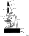
- FIG. 1 shows the microscope system 10, which has at least one commercially available microscope 18, a beam module 12 and a detection module 14.
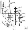
- the jet module 12 has, as in FIG. 2 a laser light source 54, whose light beam is split by means of a polarizing beam splitter 56 into a reference beam 26 and into an object beam 28.
- the object beam is coupled into an optical fiber 60 for beam cleaning purposes. After propagation through this optical fiber, the object beam 28 ideally emerges only as a Gaussian mode at the fiber end 62, which is coupled out of the beam module by means of a lens and a mirror 58 at an angle to the image plane of the figure and fed into the microscope 18 ,
- the object beam 28 takes a normal course within the microscope 18. It illuminates the slide and the object to be examined in the region of the object table and is ultimately continued by the lens 16 in the tube 20 of the microscope, so that in the image plane lying in the tube an image of examining object arises.
- the detection module 14 is arranged on the tube 20 of the microscope 18, in which the object beam 28 is non-linearly coupled to the reference beam 26.
- a photorefractive medium 24 for example in the form of a photorefractive polymer or a photorefractive crystal provided.
- the reference beam 26 is in this case coupled via a laterally and at an angle to the detection module 14 extending coupling unit 36 into the detection module 14. The object beam 28 and the reference beam 26 thus meet each other at a predetermined angle in the nonlinear optical medium 24.
- an image acquisition system 42 which typically has a two-dimensional CCD chip, so that the processes running dynamically in the object can be further processed electronically in a simple manner.
- a photodetector 40 is provided, which is designed to measure the beam intensity of the reference beam 26.
- a beam part 52 part of the reference beam 26 is coupled out to the photodetector 40 from the reference beam 26.
- a polarizer 50 for the reference beam 26 is provided in the coupling-in unit 36. This makes it possible that the polarization direction of object beam 28 and reference beam 26 can be matched to each other immediately before arrival and before the coupling in the medium 24.
- the photorefractive medium 24 is preferably arranged interchangeably in the detection module 14, so that fundamentally different materials can be used for different operating modes of the microscope system 10.
- the angle at which the object beam 28 and the reference beam 26 meet in the material 24 is substantially constant.
- an adjustment possibility for the coupling-in unit 36 or for the fiber coupling 37 of the reference beam 26 is provided.
- the reference beam 26 is detected by an optical fiber 22 from the in FIG. 2 illustrated jet module in the in FIG. 3 Coupled detection module shown.
- the fiber coupling between detection module 14 and beam module 12 provides great flexibility and interoperability for the whole Microscope system 10.
- the modular motion-detecting microscope system can thus be universally coupled to a variety of commercially available microscopes 18. As a result, in particular the adjustment effort for the coupling of the reference beam 26 into the detection module 14 can be reduced to a minimum.
- jet module 12 has a plurality of electrically controllable and adjustable optical elements, such as a filter (neutral density filter NDF) 44, a piezo-mechanically adjustable mirror 46, a rotatable ⁇ / 2-delay plate 48 on.
- a filter neutral density filter NDF
- piezo-mechanically adjustable mirror 46 a piezo-mechanically adjustable mirror 46
- rotatable ⁇ / 2-delay plate 48 The combination of rotatable A / 2 retardation plate and polarizing beam splitter 56 allows for adjustment of the intensity ratio of reference beam 26 and object beam 28.
- the phase relationship between the object beam 28 and the reference beam 26 can be adjusted in a targeted manner.
- the ⁇ / 4 retardation plate 47 rotates the polarization direction of the reference beam 26 so that, in the end, the reference beam 26 and the object beam 28 have an approximately same direction of polarization.
- the rotatable by means of an actuator NDF 44 serves to control the intensity of the object beam 28th
- polarizer 50 can finally be made a further intensity control of the reference beam 26. It is therefore intended that Also, the polarizer 50 is formed by means of an actuator electromechanically adjustable.
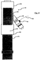
- FIG. 4 shows a schematic representation of the placed on the microscope tube 20 detection module 14, which has an outer 32 and an inner housing part 34.
- the coupling unit 36 for the reference beam 26 is in this case arranged on the inner housing part 34, in which the photorefractive medium 24 is located.
- the lens 30 provided for the focusing of the object beam 28 is arranged here in an overlapping region of the detection module 14 and the microscope tube 20.
- the opening 80 with which the detection module 14 can be pushed onto the eyepiece attachment of the tube 20, typically has a standard dimension, such as a C-mount connection, thus enabling easy and safe replacement of the detection module 14.
- Similar connection possibilities for the Jardinakquisesystem 42 has the output port 82 of the detection module 14, which is formed at the front end portion of the outer housing part 32.
- the inner 34 and the outer 32 housing part are formed along the optical axis of the object beam 28 against each other displaceable. In this way, the am Inner housing part 34 arranged non-linear medium 24 are moved on the optical axis of the object beam 28 such that the focal point of the object beam 28 always comes to rest even with a replacement of the lens 16 of the microscope 18 within the medium 24.
- the different and universally interchangeable lenses 16 of the microscope 18 associated focus positions of the object beam 28 are typically stored in a mapping table and can be read and processed for automatic and largely automated adjustment of inner and outer housing part 32, 34.
- FIG. 3 shows a schematic external view of a detection module 14 placed on a tube 20 FIG. 4 .
- Inner and outer housing part 34, 32 are formed as a substantially cylindrical sleeve, wherein the outer sleeve 32 has axially extending openings on the outer wall. These recesses in the outer cylinder jacket are required for the axial displacement of the inner sleeve 34 since the coupling unit 36 for the reference beam 26 is arranged laterally thereon.
- the detectable by the photodetector 40 intensity of the reference beam 26 is forwarded by means of a cable 68 to a control or evaluation module.
- FIG. 6 shows a schematic block diagram of the microscope system with a control module 70, which has input and output means 74 as well as processor-controlled control means 72.
- the object beam generated by the beam module 12 through the microscope 18 and through the Detection module 14 propagates and ultimately hits the CCD chip 42, the reference beam is coupled directly from the beam module via fiber coupling 22 in the detection module 14.
- all optical components of the beam module 12 and the detection module 14 can be controlled directly via the control module 70.
- the intensity values measured by the photodetector 40 can be evaluated system-internally.
- the control module can be controlled via input and output means 74 directly by a user of the microscope system 10.
- the control module 70 has an interface for coupling to a network 76, so that the entire system can also be controlled and operated by means of external control modules 78.
- an interface or transmission means in particular RS 232, Ethernet, W-LAN, IRDA, Bluetooth and the like in question.
- the external control can take place here via a web interface or via web services, for example by means of a CGI interface.
- FIG. 7 is a block diagram of a schematic coupling of a single beam module 84 with a plurality of microscopes or microscope systems 98, 100, 102 shown.
- the beam module has for this purpose a plurality of optical interfaces 86, 88, 90, by means of which the individual microscopes 98, 100, 102 can be coupled to the beam module 82 via light-conducting fibers 92, 94, 96.
- the fiber couplings 92, 94, 96 are examples of a coupling of each object beam and reference beam.
- an external beam source in particular from a laser 104
- existing and external light sources can be universally coupled to the system, so that ultimately multiple and possibly spatially separately positioned beam modules and / or microscope system can be powered by a common light source, which can contribute to further cost minimization.
Landscapes
- Physics & Mathematics (AREA)
- Chemical & Material Sciences (AREA)
- Analytical Chemistry (AREA)
- General Physics & Mathematics (AREA)
- Optics & Photonics (AREA)
- Microscoopes, Condenser (AREA)
- Investigating Or Analysing Materials By Optical Means (AREA)
- Optical Couplings Of Light Guides (AREA)
Description
- Die vorliegende Erfindung betrifft ein Detektionsmodul zur Anbindung an ein Mikroskop zur Herstellung eines bewegungsdetektierenden Mikroskopsystems und ein bewegungsdetektierendes Mikroskopsystem zur Visualisierung dynamischer Vorgänge und Prozesse, basierend auf dem Prinzip eines photorefraktiven Neuigkeitsfilters.
- Ein auf photorefraktiver Strahlkopplung basierender optischer Neuigkeitsfilter ist als solches im Stand der Technik bekannt. Dieser stellt einen zeitlichen Hochpassfilter zur Verfügung, der ausschließlich dynamische Veränderungen in einem Bild sichtbar macht und einen stationären Hintergrund unterdrückt.
- So ist beispielsweise in der
US 5,005,927 ein nichtlinear optisches Mikroskopsystem beschrieben, welches eine nichtlineare Kopplung optischer Strahlen in einem photorefraktiven Bariumtitanatkristall ausnutzt. Hierbei werden ein Referenzstrahl und ein mit Bildinformationen versehener Objektstrahl fortwährend in einem photorefraktiven Material kohärent überlagert, sodass in der Schnittebene der beiden Strahlen ein transientes Volumenhologramm im Material gespeichert wird. - Abhängig von der Intensitätsverteilung und Phasenlage der beiden nichtlinear miteinander koppelnden Strahlen entsteht eine Brechungsindexmodulation im photorefraktiven Medium, die im Falle eines Bariumtitanatkristalls um 90 Grad zur Intensitätsverteilung der Strahlen phasenverschoben ist. Bei einem stationären Objektstrahl kommt es aufgrund dieser Phasenverschiebung zur destruktiven Interferenz, sodass letztlich ein vollständig schwarzes Bild am Kristallausgang zu beobachten ist. Unterliegt der Objektstrahl jedoch einer zeitlichen Intensitäts- oder Phasenänderung, so wird diese instantan am Kristallausgang sichtbar, da eine entsprechende Änderung der Brechungsindexmodifikation des Materials eine gewisse Zeitdauer in Anspruch nimmt innerhalb welcher die Bedingungen für eine vollständige destruktive Interferenz nicht erfüllt sind. Auf diese Art und Weise können Intensitäts- und Phasenveränderungen des Objektstrahls instantan und in Echtzeit visualisiert werden.
- Der auf der photorefraktiven Strahlkopplung basierende Neuigkeitsfilter eignet sich daher hervorragend für Untersuchungen von Strömungsfeldern und deren zeitlichen Dichteschwankungen, die sich unmittelbar auf die räumliche Phasenverteilung eines Lichtstrahls auswirken.
- Aus
DE 42 31 470 A1 ist ein modulares Mikroskopsystem bekannt, das aus zusammengesetzten Grundkörpermodulen besteht und dem weitere Module zugeordnet werden können. Das modular konzipierte Mikroskopsystem ist in servicefreundlicher Baugruppenmontage herstellbar. Zur Analyse von dynamischen Vorgängen ist das Mikroskopsystem nicht ausgelegt. - Aus
DE 103 50 918 B3 und ausDE 101 00 247 A1 sind Mikroskopsysteme bekannt, die auf der Basis einer punktförmigen Objektabtastung arbeiten. Solche Mikroskopiesysteme sind zur Analyse dynamischer Vorgänge oder Prozesse mit hohen Bewegungsgeschwindigkeiten in zweidimensionalen Bildfeldern prinzipiell nicht verwendbar. - Aus
WO 2004/023185 A1 ist ein Kamera-Adapter bekannt, durch den es möglich ist, beliebige Video- und Fotokameras an einen Strahlenteiler eines Mikroskops anzuschließen. Der zwischen dem Strahlenteiler und der Kamera anzuordnende Kamera-Adapter besteht aus einem Gehäuse mit zwei Anschlussstutzen. Im Gehäuse des Kamera-Adapters sind ein 90°-Prisma und ein Spiegel als zusätzliche strahlenlenkende Elemente so angeordnet, dass die optischen Achsen der Anschlussstutzen einen Winkel kleiner als 180° einschließen. - Aus
DE 38 04 198 A1 ist ein Adapter für ein Mikroskop bekannt. Der Adapter weist eine Abbildungslinse auf. Ein Prisma reflektiert einfallendes Licht zweimal, um das Licht in einer Richtung zu emittieren, die unter einem Winkel vom 135° mit der optischen Einfallsachse verläuft. Ein Doppelspiegel kann derart um eine Drehachse schwenken, dass er wahlweise in einer von zwei Positionen angeordnet werden kann. Der Adapter wird mit einer Montagebuchse des Mikroskops zusammengekoppelt. Eine Stumm- und eine TV-Kamera werden ebenfalls an entsprechende Buchsen des Adapters angeschlossen. - In den Lebenswissenschaften, insbesondere in der Systembiologie ist die Beobachtung von sich bewegenden Mikro- und Nano-Objekten sowie die ganzheitliche in Vivo Analyse der Dynamik in biologischen Funktionssystemen erforderlich. Es können prinzipiell Aufschlüsse über die Entwicklung und das Verhalten von lebenden Organismen, über Vorgänge in Organen, über Stoffwechselvorgänge oder über die intra- und interzelluläre Dynamik gewonnen werden. Gleichzeitig treten in diesen Anwendungsgebieten zunehmend strömungsmechanische Fragestellungen im mikroskopischen Längenmaßstab auf. Insbesondere in der Medizin ist die Charakterisierung und Untersuchung der Strömungsverhältnisse in biologischen oder künstlichen Kapillaren zur Erkennung und zur Prävention von Krankheiten äußerst wichtig.
- Eine herkömmliche mikroskopische Beobachtung solch biologischer Objekte und chemischer Reaktanten ist kaum möglich, da die Objekte zumeist vollständig transparent sind. Zwar kann prinzipiell das Zernickesche Phasenkontrastverfahren verwendet werden, doch wird hierbei auch gleichzeitig ein von einer Trägersubstanz oder von anderen stationären Mikroobjekten rührender stationärer Hintergrund sichtbar, was gerade für die Beobachtung dynamischer Prozesse von Nachteil ist. Andere Mikroskopieverfahren, wie etwa die konfokale Mikroskopie, arbeiten auf einem Abtastprinzip und sind daher a priori nicht in der Lage, dynamische Vorgänge oder Prozesse mit hohen Bewegungsgeschwindigkeiten in zweidimensionalen Bildfeldern zuverlässig zu analysieren.
- Die aus dem Stand der Technik bekannten photorefraktiven Neuigkeitsfilter sind bislang für eine gewerbliche Anwendung kaum geeignet, da für eine effiziente Kopplung von Objekt- und Referenzstrahl die einzelnen Strahlparameter, wie etwa Strahlintensität, Polarisationsrichtung sowie eine relative Phase der im photorefraktiven Medium miteinander koppelnden Strahlen präzise eingestellt und gegebenenfalls nachjustiert werden müssen. Der Betrieb eines photorefraktiven Neuigkeitsfilters ist daher bislang Fachkräften auf dem Gebiet der nichtlinearen Optik vorbehalten, die profunde Kenntnisse zur Justage und über den grundlegenden Aufbau eines solchen Systems verfügen.
- Der vorliegenden Erfindung liegt daher die Aufgabe zugrunde, eine Möglichkeit anzubieten, ein bedienerfreundliches, wartungsarmes und zudem vielseitig einsetzbares bewegungsdetektierendes Mikroskopsystem zur Verfügung zu stellen, das auch von Endbenutzern bedienbar ist, die nur über geringe Kenntnisse zur Mikroskopie im Allgemeinen verfügen. Darüber hinaus soll das Mikroskopsystem vielseitig einsetzbar und unter Verwendung handelsüblicher Mikroskope, ausgebildet sein.
- Das der Erfindung zugrunde liegende Problem wird mittels eines Detektionsmoduls gemäß Patentanspruch 1 bzw. eines Mikroskopsystems gemäß Patentanspruch 8 gelöst. Weitere vorteilhafte Ausführungsformen der Erfindung sind in den Unteransprüchen angegeben.
- Die Erfindung betrifft ein Detektionsmodul mit den Merkmalen des Anspruchs 1 für ein bewegungsdetektierendes modulares Mikroskopsystem, das mit einer für den Objektstrahl des Mikroskops vorgesehenen Aufnahme am Tubus des Mikroskops lösbar anordenbar ist. Das Detektionsmodul weist insbesondere ein nichtlinear optisches Medium auf, in welchem der vom Mikroskopobjektiv abgebildete Objektstrahl mit einem dazu kohärenten Referenzstrahl koppelt.
- Die Aufnahme zur Anbindung an den Tubus des Mikroskops ist vorzugsweise als runde Öffnung ausgestaltet, mit welcher das Detektionsmodul anstelle eines Okulars auf den Mikroskoptubus aufgeschoben und dort lösbar befestigt werden kann. Von Vorteil ist hierbei, wenn sowohl der Mikroskoptubus als auch die Aufnahme des Detektionsmoduls einen standardisierten Durchmesser und/oder ein standardisiertes Gewindemaß oder dergleichen Befestigungsmittel aufweisen.
- Beispielsweise sind sowohl der Mikroskoptubus als auch die Aufnahme des Detektionsmoduls als C-Mount ausgebildet. Die Wahl eines solchen oder eines vergleichbaren Standardmaßes für die Anbindung zwischen den einzelnen Modulen des Mikroskopsystems ist für eine vielseitige Verwendbarkeit der einzelnen Module von Vorteil.
- Das Detektionsmodul, in welchem letztlich die Strahlkopplung stattfindet, weist insbesondere Mittel zur relativen Justage und Kalibrierung für den Objektstrahl und/oder den Referenzstrahl auf, sodass eine möglichst effektive Strahlkopplung, vorzugsweise selbsttätig durch das System eingestellt werden kann.
- Nach einer weiteren Ausführungsform ist das Detektionsmodul dazu ausgebildet, dass an einer dem Tubus gegenüberliegenden Strahlaustrittsöffnung ein Bilderfassungssystem lösbar befestigt werden kann. Beispielsweise können auch hier, ähnlich wie bei der Anbindung des Detektionsmoduls an den Tubus vergleichbare beziehungsweise ähnlich standardisierte Verbindungsmittel, wie etwa eine C-Mount-Schnittstelle, Verwendung finden.
- Als Bilderfassungssystem kommen vorzugsweise Charge Coupled Device (CCD) Kameras (CCD) zum Einsatz, die zur unmittelbaren Bildakquise eines zweidimensionalen Bildes am Ausgang des Detektionsmoduls geeignet sind. Die mittels des Bilderfassungssystems aufgenommenen zweidimensionalen Bilder können anschließend zur elektronischen Weiterverarbeitung einem Computersystem oder dergleichen Bildauswertesystem zugeführt werden.
- Weiterhin ist für das Detektionsmodul eine Strahleinkopplungseinheit zur Einkopplung des Referenzstrahls in das nichtlineare optische Medium vorgesehen. Diese Strahleinkopplungseinheit weist vorzugsweise eine Faserkupplung auf, an welcher eine den Referenzstrahl führende optische Faser gekoppelt werden kann. Die Faserkupplung ist derart ausgebildet, dass der von der Faser zur Verfügung gestellte Referenzstrahl stets unter dem gleichen vorgegebenen Winkel zur optischen Achse des Objektstrahls auf das nichtlinear optische Medium trifft.
- Zur Justage und/oder Kalibrierung das Detektionsmoduls ist insbesondere vorgesehen, dass die Strahleinkopplungseinheit zumindest aber deren Faserkupplung in wenigstens zwei, vorzugsweise in allen drei Raumrichtungen justierbar ist.
- Somit kann der Referenzstrahl exakt an eine vorgegebene Position auf das nichtlineare Medium justiert werden, welche im Bedarfsfall auch manuell geändert werden kann.
- Des Weiteren ist vorgesehen, dass das Detektionsmodul zumindest ein inneres Gehäuseteil und ein äußeres Gehäuseteil aufweist, wobei inneres und äußeres Gehäuseteil in Richtung zur optischen Achse des Objektstrahls zueinander verschiebbar sind. Hierbei ist insbesondere vorgesehen, dass die beiden Gehäuseteile mittels eines elektrisch ansteuerbaren Stellantriebs gegeneinander verschiebbar sind.
- Nach einer weiteren Ausführungsform ist das innere Gehäuseteil zumindest bereichsweise in dem äußeren Gehäuseteil des Detektionsmoduls geführt. Die beiden Gehäuseteile weisen vorzugsweise eine zylindrische Geometrie auf, wobei an der Wandung des äußeren Gehäuseteils einzelne in Axialrichtung verlaufende Aussparungen vorgesehen sind, die eine relative axiale Verschiebbarkeit der beiden Gehäuseteile auch dann ermöglichen, wenn beispielsweise von außen zugeführte Funktionsteile, wie etwa die Strahleinkopplungseinheit an dem inneren Gehäuseteil befestigt sind.
- Von Vorteil ist weiterhin, dass die optische Weglänge zwischen dem nichtlinear optischen Medium und dem Objektiv des Mikroskops durch relatives Verschieben von innerem und äußerem Gehäuseteil einstellbar ist. Einer Axialverschiebung des Fokuspunktes des Objektstrahls infolge eines Objektivwechsels kann daher durch entsprechendes Verschieben von innerem und äußerem Gehäuseteil kompensiert werden, sodass letztlich stets sichergestellt werden kann, dass sich das nichtlinear optische Medium in einem konstanten Abstand zum Fokuspunkt des Objektstrahls befindet.
- Nach einer weiteren Ausführungsform ist die Strahleinkopplungseinheit seitlich und unter einem Winkel zur optischen Achse des Objektstrahls an dem inneren Gehäuseteil angeordnet.
- Des Weiteren ist auch das nichtlinear optische Medium austauschbar im Detektionsmodul angeordnet. Das Medium steht hierbei vorzugsweise in direkter mechanischer Wirkverbindung mit dem inneren Gehäuseteil, sodass die Position des nichtlinear optischen Mediums relativ zur Strahleinkopplungseinheit im Wesentlichen konstant bleibt. Im Wesentlichen bleibt der über die Faser eingekoppelte Referenzstrahl bezüglich des nichtlinearen Mediums fixiert.
- Nach einer weiteren vorteilhaften Ausführungsform der Erfindung ist zur Fokussierung des Referenzstrahls in das nichtlinear optische Medium zumindest ein fokussierendes optisches Element im Detektionsmodul vorgesehen. Dieses befindet sich vorzugsweise im Bereich der seitlich angeordneten Strahleinkopplungseinheit. Eine Fokussierung des Referenzstrahls ist zur Steigerung der Kopplungseffizienz zwischen Objektstrahl und Referenzstrahl von Vorteil.
- Weiterhin ist vorgesehen, dass zur Bestimmung der Intensität des Referenzstrahls die Strahleinkopplungseinheit des Detektionsmoduls zumindest einen Fotodetektor aufweist. Somit können zuverlässige Messwerte über die tatsächlich am nichtlinearen Medium vorliegende Intensität des Referenzstrahls gewonnen werden. Die vom Fotodetektor ermittelbaren Messwerte können zur Regelung einer optimalen Kopplung im nichtlinearen Medium Verwendung finden. So können beispielsweise die Gesamtintensität von Objekt- und Referenzstrahl als auch das Intensitätsverhältnis der beiden Strahlen präzise bestimmt und entsprechend selbsttätig nachgeregelt werden.
- Nach einem unabhängigen Aspekt betrifft die Erfindung ein bewegungsdetektierendes Mikroskopsystem, welches ein Strahlmodul und ein Detektionsmodul aufweist. Zudem ist ein Mikroskop vorgesehen, das zumindest ein Objektiv und einen Tubus aufweist. Das Strahlmodul ist zur Erzeugung zumindest eines Referenzstrahls und eines dazu im Wesentlichen kohärenten Objektstrahls vorgesehen, während das Detektionsmodul zur Kopplung des Referenzstrahls mit dem Objektstrahl ein nichtlinear optisches Medium aufweist.
- Die vom Strahlmodul erzeugbaren Strahlen Referenzstrahl und Objektstrahl werden im Detektionsmodul in einem nichtlinear optischen Medium gekoppelt, wobei der Objektstrahl zuvor mit einem zu untersuchendem Objekt, wie etwa einem im Wesentlichen transparenten Phasenobjekt, wechselwirkt und somit zum Träger einer objektspezifischen Bildinformation wird. Durch die kohärente Überlagerung von Objektstrahl und Referenzstrahl im nichtlinear optischen Medium, wie etwa einem photorefraktiven Kristall, können dynamische Veränderungen des Objekts anhand der nichtlinearen Kopplung zwischen den beiden Strahlen instantan und zweidimensional ortsaufgelöst visualisiert werden.
- Das erfindungsgemäße bewegungsdetektierende Mikroskopsystem zeichnet sich insbesondere durch seinen modularen Aufbau aus. Die Module zur Strahlerzeugung und zur Kopplung von Objekt- und Referenzstrahl sind insbesondere für eine Adaption an handelsübliche Mikroskope vorgesehen, sodass prinzipiell jedes kommerziell erhältliche optische Mikroskop mittels eines Strahlmoduls und eines darauf abgestimmten Detektionsmoduls zu einem erfindungsgemäßen bewegungsdetektierenden modularen Mikroskopsystem aufgerüstet oder adaptiert werden kann.
- Jedem dieser einzelnen miteinander kombinierbaren Module, Strahlmodul, Detektionsmodul kommt eine eigene Funktion zu. So dient das zumindest ein Objektiv und einen Tubus aufweisende Mikroskop zur Vergrößerung des Objektstrahls, wodurch letztlich ein vergrößertes Abbild des zu beobachtenden Objekts erzeugt werden kann. Das Strahlmodul hat hierbei die Aufgabe, unter Berücksichtigung sämtlicher für die Strahlkopplung relevanter Parameter, wie etwa transversale Strahlgeometrie und Strahlverlauf, Intensität und/oder Polarisation sowohl den Objekt- als auch den Referenzstrahl für das Gesamtsystem zur Verfügung zu stellen.
- Die optische Weglänge zwischen dem nichtlinear optischen Medium und dem Objektiv des Mikroskops kann variabel eingestellt werden.
- Es ist hierbei insbesondere vorgesehen, dass die optische Weglänge zwischen dem nichtlinear optischen Medium und dem Objektiv mittels zumindest eines elektrisch betätigbaren Stellantriebs einstellbar ist. In diesem Zusammenhang ist beispielsweise vorgesehen, dass das nichtlinear optische Medium entweder innerhalb des Detektionsmoduls auf der optischen Achse des Objektstrahls verfahrbar ist, oder dass Teile des Detektionsmoduls oder gar das gesamte Detektionsmodul bezogen auf die Position des Objektivs entlang der optischen Achse des Objektstrahls gezielt verschoben werden kann.
- Je nach verwendetem Mikroskopobjektiv und Mikroskoptyp kann somit das nichtlinear optische Medium stets an eine Position auf der optischen Achse des Objektstrahls verschoben werden, die für eine nichtlineare Kopplung mit dem Referenzstrahl besonders gut geeignet ist. Eine solche für das nichtlinear optische Medium optimale Position kann etwa durch einen Fokuspunkt des Objektstrahls innerhalb des optischen Systems Mikroskop oder Detektionsmodul vorgegeben sein.
- Zur Fokussierung des Objektstrahls in das nichtlinear optische Medium kann zumindest ein fokussierendes optisches Element, insbesondere eine fokussierende Linse vorgesehen sein. Diese Linse ist vorzugsweise in Propagationsrichtung des Objektstrahls hinter einer Bildebene des Mikroskops angeordnet. Sie kann hierzu beispielsweise im Tubus aber auch im Detektionsmodul angeordnet sein. Das fokussierende optische Element kann natürlich auch durch ein Linsensystem realisiert werden, das sowohl im Mikroskoptubus als auch im Detektionsmodul ausgebildet ist. Alternativ kommen als fokussierende optische Elemente auch grundsätzlich so genannte diffraktive optische Elemente infrage.
- Weiterhin ist vorgesehen, dass Strahlintensität und Polarisationsrichtung von Objektstrahl und/oder Referenzstrahl und/oder die Phasenbeziehung zwischen Objektstrahl und Referenzstrahl mittels elektromechanischer optischer Elemente einstellbar ist. Hierfür kommen insbesondere drehbare oder verschiebbare optische Elemente, wie λ/2- oder λ/4-Verzögerungsplatten, drehbare lineare Polarisatoren sowie mittels Piezomechanik verschiebbare Spiegel zum Einsatz.
- Die elektromechanische Ansteuerung der optischen Elemente erfolgt typischerweise mittels Schritt- und/oder Linearmotoren. Die Linearbewegung der auf Piezokristallen befestigten Spiegel kann in einfacher Art und Weise durch Beaufschlagung mit elektrischer Spannung geeigneter Amplitude erfolgen. Das Einstellen sämtlicher Parameter von Objekt- und Referenzstrahl macht ein manuelles Eingreifen eines Anwenders überflüssig.
- Durch die elektromechanisch ansteuerbaren optischen Elemente kann ein Höchstmaß an Automatisierung zur Verfügung gestellt werden, die eine selbsttätige Justage und Kalibrierung des Systems ermöglicht. Zudem können die sensiblen und zumeist nur schwierig von Verunreinigungen und Staub zu befreienden optischen Komponenten in einem staubdicht verschlossenen Gehäuse untergebracht werden. Somit wird zum einen ein manuelles Eingreifen des Anwenders überflüssig und zum anderen können diejenigen Module, in denen diese optischen Elemente angeordnet sind, für den Anwender unzulänglich und effektiv vor Verunreinigungen geschützt, fest verschlossen ausgebildet werden.
- Des Weiteren ist ein derartiger nach außen verschlossener Aufbau hinsichtlich Laserschutzbestimmungen von Vorteil, da ein unbeabsichtigtes Austreten von Laserstrahlung aus dem Strahlmodul effektiv vermieden werden kann.
- Für die Übertragung des Referenzstrahls vom Strahlmodul zum Detektionsmodul kann eine optische Faser, vorzugsweise eine Mono-Mode Faser vorgesehen sein. Hierbei ist insbesondere von Vorteil, dass die optische Faser sowohl am Strahlmodul als auch am Detektionsmodul mittels entsprechender Faserkopplungen lösbar befestigt werden kann. Die Übertragung des Referenzstrahls mittels einer optischen Faser erlaubt eine universelle und flexible Anordnung von Strahlmodul und Detektionsmodul. Sie ermöglicht sogar das universelle Austauschen unterschiedlicher Strahl- oder Detektionsmodule.
- Die Faserein- bzw. -auskopplung für den Referenzstrahl stellt eine Interoperabilität zur Verfügung, mittels derer es prinzipiell möglich ist, die erfindungsgemäßen Strahl- und Detektionsmodule an nahezu jedes Lichtmikroskop anzubinden.
- Die Verwendung einer Mono-Mode Faser hat zudem den Vorteil, dass lediglich die räumliche Grundmode des Referenzstrahls, nämlich dessen Gauß-Mode übertragen wird, sodass ein modengefilterter Referenzstrahl mit einem homogenen beziehungsweise symmetrischen Strahlprofil in das Detektionsmodul eingekoppelt wird.
- Für das Mikroskopsystem ist weiterhin vorgesehen, dass als nichtlinear optisches Medium ein photorefraktives Material, insbesondere ein photorefraktives Polymer oder ein photorefraktiver Kristall, hierunter insbesondere Lithiumniobat oder Bariumtitanat vorgesehen ist. Weitere in Frage kommende Materialien sind zum Beispiel Lithiumtantalat, Photopolymere, elektrooptische photorefraktive Polymere oder Polymer- beziehungsweise Flüssigkristallmischsysteme.
- Photorefraktive Kristalle zeichnen sich durch hohe Nichtlinearitäten und hohe Kopplungskonstanten für die Zweistrahl-Kopplung aus, die vor allem bereits bei sehr geringer Lichtleistung im Bereich einiger Mikrowatt oder gar einiger Nano-Watt auftreten. Von daher ist die Verwendung derartiger Kristalle vorteilhaft wenn das zu untersuchende Objekt keiner hohen Strahlungsleistung ausgesetzt werden soll.
- Während Bariumtitanat zur Klasse der diffusions-dominierten photorefraktiven Materialien zählt, deren eingeschriebenes Brechungsindexgitter sich nach einer Zeitdauer τ an eine geänderte Intensitätsverteilung innerhalb des Materials anpasst, weist Lithiumniobat eine Zeitkonstante τ in der Größenordnung einiger Stunden auf, die es ermöglicht, dauerhaft eine Brechungsindexstruktur im Material zu speichern.
- Lithiumniobat eignet sich daher in einem neuigkeitsfilternden System zu einem Vergleich mit einem zuvor im Material gespeicherten Referenzbild, während Bariumtitanat zur Visualisierung plötzlicher dynamischer Veränderungen geeignet ist, die - sofern keine weitere Veränderung im Objektstrahl auftritt - in ihrer Intensität abklingt und nach einer Zeitdauer von typischerweise einigen Sekunden als statischer Hintergrund am Ausgang des Neuigkeitsfilters nicht mehr als Neuigkeit zu erkennen ist.
- Da Lithiumniobat nicht zu den diffusionsbestimmten Kristallen zählt und somit auch keine merkliche Zweistrahlkopplung zeigt, ist es für die Implementierung eines neuigkeitsfilternden Systems erforderlich, einen künstlichen Phasenversatz auf den Referenzstrahl zu geben, nachdem das ursprüngliche Gitter in den Kristall geschrieben ist. Nähere Informationen zur Neuigkeitsfilterung mit photorefraktivem Lithiumniobat gehen aus V. Krishnamachari, Grothe et al. "Novelty filtering with a photorefractive lithium-niobate crystal", Applied Physics letters 87, 071105 (2005) hervor, deren Inhalt vollumfänglich zum Offenbarungsgehalt dieser Anmeldung zu zählen ist.
- Weiterhin ist vorgesehen, dass die Strahleinkopplungseinheit des Detektionsmoduls einen verstellbaren Polarisator aufweist, der eine präzise Abstimmung der Polarisationsrichtung von Objektstrahl und Referenzstrahl direkt vor einer Einkopplung in das nichtlinear optische Medium ermöglicht.
- Es ist ein Steuermodul für das Mikroskopsystem vorgesehen, welches zum Einstellen der Intensität und/oder Polarisationsrichtung von Objektstrahl und/oder Referenzstrahl ausgebildet ist. Darüber hinaus kann es alternativ oder ergänzend zum Einstellen der Phase zwischen Objektstrahl und Referenzstrahl vorgesehen werden. Das Steuermodul dient in erster Linie einer elektrischen Ansteuerung von elektromechanischen optischen Elementen zur Regulierung sämtlicher Strahlparameter. Das Steuermodul kann hierbei in das Mikroskopsystem, beispielsweise in das Strahlmodul oder in das Detektionsmodul integriert sein. Wahlweise kann das Steuermodul jedoch auch als externes eigenständiges Modul implementiert werden, welches wahlweise zur Kalibrierung und/oder zum Betrieb des Mikroskopsystems an einzelne Komponenten oder Module des Mikroskopsystems nach Bedarf ankoppelbar ist.
- Nach einer weiteren Ausführungsform sind für das Steuermodul Steuermittel vorgesehen, die der Fokusposition des Objektstrahls und/oder der Objektbrennweite des Mikroskops entsprechend zum selbsttätigen Einstellen der optischen Weglänge zwischen Objektiv und dem nichtlinear optischen Medium ausgebildet sind.
- Das Steuermodul weist weiterhin zumindest eine Schnittstelle zur Übertragung von Daten und/oder Steuerbefehlen zwischen dem Steuermodul und dem Strahlmodul und/oder dem Detektionsmodul und/oder einem externen Kontrollmodul auf. Es sind ferner auch Eingabe- und Ausgabemittel am Steuermodul vorgesehen, die dem Benutzer die unmittelbare Kontrolle des Mikroskopsystems über das Steuermodul ermöglichen.
- Ein Strahlmodul weist elektromechanische optische Elemente auf, die zum Einstellen von Intensität und/oder Polarisationsrichtung von Objektstrahl und/oder Referenzstrahl und/oder die zum Einstellen der Phase zwischen dem Objektstrahl und dem Referenzstrahl ausgebildet sind. Die im Strahlmodul vorgesehenen elektromechanischen optischen Elemente sind insbesondere über das Steuermodul direkt ansteuerbar.
- Weiterhin ist vorgesehen, dass das Strahlmodul zumindest eine optische Schnittstelle zur Einkopplung von Strahlung einer externen Strahlquelle aufweist. Somit kann anstelle oder alternativ zur Strahlquelle des Strahlmoduls auch eine extern vorhandene Strahlquelle Verwendung finden, die insbesondere mit faseroptischen Mitteln an das Strahlmodul und an das Mikroskopsystem angekoppelt werden kann. Dies erlaubt eine effiziente Nutzung und Auslastung einer in der Anschaffung kostenintensiven Laserlichtquelle.
- In einer weiteren vorteilhaften Ausführungsform sind an dem Strahlmodul mehrere optische Schnittstellen zur Kopplung mehrerer Referenz- und/oder Objektstrahlen für eine Vielzahl von Mikroskopen vorgesehen. Auf diese Art und Weise kann ein einziges Strahlmodul als Strahlquelle für eine Vielzahl von Mikroskopen dienen, die auch räumlich getrennt voneinander aufgestellt und betrieben werden können. Da für eine effiziente Kopplung sowohl der Objekt- als auch der Referenzstrahl einen recht hohen Kohärenzgrad aufweisen müssen, kommt als Lichtquelle zumeist nur eine hochwertige und in der Anschaffung recht kostenintensive Laserlichtquelle infrage. Die Möglichkeit, eine Vielzahl von Mikroskopen oder Mikroskopsystemen mit einem einzigen Strahlmodul unter Einsatz lichtleitender Fasern zu speisen, reduziert den Kostenaufwand erheblich und macht das System universell einsetzbar.
- Von Vorteil ist weiterhin, dass das Strahlmodul zur Erzeugung von zumindest zwei Objektstrahlen und/oder zwei Referenzstrahlen unterschiedlicher Wellenlänge ausgebildet ist. Die Referenz- und Objektstrahlen weisen hierbei paarweise identische Wellenlängen auf, so dass sie paarweise im nichtlinearen Medium miteinander wechselwirken können. Insbesondere ist hierbei vorgesehen, dass sowohl die beiden Objektstrahlen unterschiedlicher Wellenlänge als auch die beiden Referenzstrahlen unterschiedlicher Wellenlänge durch das Mikroskopsystem gleichzeitig ko-propagieren.
- Auf diese Art und Weise wird zum Beispiel eine die Messung von Phasenverschiebungen in einem Bereich größer als π ermöglicht, was somit zu einer Steigerung des Messbereichs des Mikroskopsystems führt. Als typische Wellenlängen kommen insbesondere λ=488nm oder 532nm oder λ=633nm in Frage.
- Es versteht sich von selbst, dass die anderen Module, hierunter insbesondere das Detektionsmodul, bei einer Ausstattung des Strahlmoduls mit zwei Lichtquellen unterschiedlicher Wellenlänge in entsprechender Weise an eine Zwei- beziehungsweise Vierstrahlkonfiguration angepasst werden kann.
- Es kann ein Computerprogrammprodukt mit Programmmitteln zur Steuerung des Mikroskopsystems vorgesehen sein. Die Programmmittel sind hierbei dazu ausgebildet, die in einer Datenbank oder in einem Speicher abgelegten Angaben über das im Detektionsmodul eingesetzte nichtlinear optische Medium abzufragen, die Intensität von Referenzstrahl und/oder Objektstrahl zu ermitteln, ein für die Strahlkopplung von Objektstrahl und Referenzstrahl optimales Intensitätsverhältnis zu bestimmen, und die elektromechanischen optischen Elemente des Mikroskopsystems derart anzusteuern, dass ein optimales Intensitätsverhältnis für die Strahlkopplung zwischen Referenzstrahl und Objektstrahl eingestellt wird.
- Das Computerprogrammprodukt kann Programmmittel zum Ermitteln der Brennweite des verwendeten Objektivs aufweisen und dazu ausgebildet sein, elektrische Stellantriebe derart anzusteuern, dass das im Detektionsmodul angeordnete nichtlinear optische Medium im Fokusbereich des Objektstrahl positioniert wird. Die Ermittlung der Brennweite des Objektivs kann beispielsweise über eine Speicher- oder Datenbankabfrage erfolgen.
- Weitere Merkmale, Ziele, Vorteile sowie Anwendungsmöglichkeiten der vorliegenden Erfindung ergeben sich aus der nachfolgenden Beschreibung von Ausführungsbeispielen anhand der Zeichnungen. Dabei bilden sämtliche beschriebenen und/oder bildlich dargestellten Merkmale in ihrer sinnvollen Kombination den Gegenstand der vorliegenden Erfindung, auch unabhängig von den Patentansprüchen oder deren Rückbeziehung. Es zeigen:
- Figur 1
- eine schematische Abbildung des bewegungsdetektierenden Mikroskopsystems,
- Figur 2
- die optischen Komponenten des Strahlmoduls,
- Figur 3
- die Komponenten des Detektionsmoduls,
- Figur 4
- eine schematische Darstellung des Detektionsmoduls im Querschnitt,
- Figur 5
- das Gehäuse des Detektionsmoduls,
- Figur 6
- ein Blockdiagramm der einzelnen Module des Mikroskopsystems und
- Figur 7
- ein Blockdiagramm mehrerer Mikroskope, die von einem gemeinsamen Strahlmodul gespeist werden.
-
Figur 1 zeigt das Mikroskopsystem 10, welches zumindest ein handelsübliches Mikroskop 18, ein Strahlmodul 12 sowie ein Detektionsmodul 14 aufweist. Das Strahlmodul 12 weist, wie inFigur 2 gezeigt, eine Laserlichtquelle 54 auf, deren Lichtstrahl mittels eines polarisierenden Strahlteilers 56 in einen Referenzstrahl 26 und in einen Objektstrahl 28 aufgeteilt wird. Der Objektstrahl wird zu Strahlreinigungszwecken in eine optische Faser 60 eingekoppelt. Nach erfolgter Propagation durch diese optische Faser tritt der Objektstrahl 28 idealerweise nur noch als Gauß-Mode am Faserende 62 aus, die mittels einer Linse und einem schräg zur Bildebene der Figur stehenden Spiegel 58 nach oben aus dem Strahlmodul ausgekoppelt und in das Mikroskop 18 eingespeist wird. - Der Objektstrahl 28 nimmt einen gewöhnlichen Verlauf innerhalb des Mikroskops 18. Er beleuchtet den Objektträger und das zu untersuchende Objekt im Bereich des Objekttisches und wird letztlich vom Objektiv 16 in den Tubus 20 des Mikroskops weitergeführt, sodass in der im Tubus liegenden Bildebene ein Abbild des zu untersuchenden Objekts entsteht.
- Anstelle eines Okulars ist am Tubus 20 des Mikroskops 18 das Detektionsmodul 14 angeordnet, in welchem der Objektstrahl 28 mit dem Referenzstrahl 26 nichtlinear koppelt. Für die nichtlineare Kopplung ist, wie in
Figur 3 dargestellt, ein photorefraktives Medium 24, etwa in Form eines photorefraktiven Polymers oder eines photorefraktiven Kristalls vorgesehen. Der Referenzstrahl 26 wird hierbei über eine seitlich und in einem Winkel zum Detektionsmodul 14 verlaufende Einkopplungseinheit 36 in das Detektionsmodul 14 eingekoppelt. Der Objektstrahl 28 und der Referenzstrahl 26 treffen somit in einem vorgegebenen Winkel im nichtlinear optischen Medium 24 aufeinander. - Hinter dem photorefraktiven Medium 24 ist ein Bildakquisesystem 42 vorgesehen, welches typischerweise einen zweidimensionalen CCD-Chip aufweist, sodass die im Objekt dynamisch ablaufenden Prozesse auf einfache Art und Weise elektronisch weiterverarbeitet werden können.
- Zur Erzielung einer optimalen Kopplungseffizienz zwischen Objektstrahl 28 und Referenzstrahl 26 ist insbesondere vorgesehen, dass beide Strahlen mittels entsprechender fokussierender optischer Elemente 30, 38 in das Medium 24 fokussiert werden. Weiterhin ist am Detektionsmodul 14 beziehungsweise an seiner Einkopplungseinheit 36 ein Fotodetektor 40 vorgesehen, der zur Messung der Strahlintensität des Referenzstrahls 26 ausgebildet ist. Mittels eines Strahlteiles 52 wird ein Teil des Referenzstrahls 26 zum Fotodetektor 40 aus dem Referenzstrahl 26 ausgekoppelt.
- Weiterhin ist in der Einkopplungseinheit 36 ein Polarisator 50 für den Referenzstrahl 26 vorgesehen. Hierdurch wird ermöglicht, dass die Polarisationsrichtung von Objektstrahl 28 und Referenzstrahl 26 unmittelbar vor Eintreffen und vor der Kopplung im Medium 24 aufeinander abgestimmt werden können.
- Das photorefraktive Medium 24 ist vorzugsweise austauschbar im Detektionsmodul 14 angeordnet, sodass prinzipiell unterschiedliche Materialien für unterschiedliche Betriebsmodi des Mikroskopsystems 10 Verwendung finden können.
- Der Winkel, unter welchem der Objektstrahl 28 und der Referenzstrahl 26 im Material 24 aufeinander treffen, ist im Wesentlichen konstant. Für eine Kalibrierung des Systems, insbesondere nach einem Wechsel des Mediums 24 ist jedoch eine Justagemöglichkeit für die Einkopplungseinheit 36 beziehungsweise für die Faserkupplung 37 des Referenzstrahls 26 vorgesehen.
- Der Referenzstrahl 26 wird mittels einer optischen Faser 22 vom in
Figur 2 dargestellten Strahlmodul in das inFigur 3 gezeigte Detektionsmodul eingekoppelt. Die Faserkopplung zwischen Detektionsmodul 14 und Strahlmodul 12 schafft eine große Flexibilität und Interoperabilität für das ganze Mikroskopsystem 10. Das modulare bewegungsdetektierende Mikroskopsystem kann somit an eine Vielzahl handelsüblicher Mikroskope 18 universell angekoppelt werden. Hierdurch kann insbesondere der Justageaufwand für die Einkopplung des Referenzstrahls 26 in das Detektionsmodul 14 auf ein Minimum reduziert werden. - Das in
Figur 2 schematisch dargestellte Strahlmodul 12 weist eine Vielzahl elektrisch ansteuerbarer und verstellbarer optischer Elemente, wie zum Beispiel einen Filter (neutral density filter NDF) 44, einen piezomechanisch verstellbaren Spiegel 46, eine drehbare λ/2-Verzögerungsplatte 48 auf. Die Kombination von drehbarer A/2-Verzögerungsplatte und polarisierendem Strahlteiler 56 ermöglicht eine Regulierung des Intensitätsverhältnisses von Referenzstrahl 26 und Objektstrahl 28. - Mittels des Spiegels 46 kann die Phasenbeziehung zwischen Objektstrahl 28 und Referenzstrahl 26 gezielt eingestellt werden. Die λ/4-Verzögerungsplatte 47 dreht die Polarisationsrichtung des Referenzstrahls 26, sodass im Endeffekt Referenzstrahl 26 als auch Objektstrahl 28 eine annähernd gleiche Polarisationsrichtung aufweisen. Der mittels eines Stellantriebs drehbare NDF 44 dient einer Intensitätsregulierung des Objektstrahls 28.
- Über den in
Figur 3 gezeigten und in der Einkopplungseinheit 36 des Detektionsmoduls 14 angeordneten Polarisator 50 kann schließlich eine weitere Intensitätsregulierung des Referenzstrahls 26 erfolgen. Es ist daher vorgesehen, dass auch der Polarisator 50 mittels eines Stellantriebs elektromechanisch verstellbar ausgebildet ist. - Die elektrische Ansteuerbarkeit sämtlicher optischer Komponenten 44, 46, 48, 50 ermöglichen eine weitgehend automatisierte Kalibrierung und Abstimmung des modularen Mikroskopsystems 10.
-
Figur 4 zeigt eine schematische Darstellung des auf den Mikroskoptubus 20 aufgesetzten Detektionsmoduls 14, welches ein äußeres 32 und ein inneres Gehäuseteil 34 aufweist. Die Einkopplungseinheit 36 für den Referenzstrahl 26 ist hierbei an das innere Gehäuseteil 34 angeordnet, in welchem sich auch das photorefraktive Medium 24 befindet. Die für die Fokussierung des Objektstrahls 28 vorgesehene Linse 30 ist hier in einem Überlappungsbereich von Detektionsmodul 14 und Mikroskoptubus 20 angeordnet. - Die Öffnung 80, mit welcher das Detektionsmodul 14 auf den Okularansatz des Tubus 20 aufgeschoben werden kann, weist typischerweise ein Standardmaß, wie etwa einen C-Mount-Anschluss auf, womit ein leichtes und sicheres Auswechseln des Detektionsmoduls 14 ermöglicht wird. Ähnliche Anschlussmöglichkeiten für das Bildakquisesystem 42 weist die Ausgangsöffnung 82 des Detektionsmoduls 14 auf, die am stirnseitigen Endabschnitt des äußeren Gehäuseteils 32 ausgebildet ist.
- Das innere 34 und das äußere 32 Gehäuseteil sind entlang der optischen Achse des Objektstrahls 28 gegeneinander verschiebbar ausgebildet. Auf diese Art und Weise kann das am inneren Gehäuseteil 34 angeordnete nichtlineare Medium 24 auf der optischen Achse des Objektstrahles 28 derart verschoben werden, dass der Fokuspunkt des Objektstrahls 28 auch bei einem Auswechseln des Objektivs 16 des Mikroskops 18 stets innerhalb des Mediums 24 zu liegen kommt.
- Die den unterschiedlichen und universell auswechselbaren Objektiven 16 des Mikroskops 18 zugeordneten Fokuspositionen des Objektstrahls 28 werden typischerweise in einer Zuordnungstabelle hinterlegt und können zum selbsttätigen und weitgehend automatisierten Verstellen von innerem und äußerem Gehäuseteil 32, 34 ausgelesen und verarbeitet werden.
-
Figur 5 zeigt schließlich eine schematische Außenansicht eines auf einen Tubus 20 aufgesetzten Detektionsmoduls 14 gemäßFigur 4 . Inneres und äußeres Gehäuseteil 34, 32 sind als im Wesentlichen zylindrische Hülse ausgebildet, wobei die äußere Hülse 32 in Axialrichtung verlaufende Durchbrechungen an der Außenwandung aufweist. Diese Ausnehmungen im äußeren Zylindermantel sind für das axiale Verschieben der inneren Hülse 34 erforderlich, da an dieser die Einkopplungseinheit 36 für den Referenzstrahl 26 seitlich angeordnet ist. Die vom Fotodetektor 40 ermittelbare Intensität des Referenzstrahls 26 wird mittels eines Kabels 68 an ein Steuer- oder Auswertemodul weitergeleitet. -
Figur 6 zeigt ein schematisches Blockdiagramm des Mikroskopsystems mit einem Steuermodul 70, welches über Ein- und Ausgabemittel 74 als auch über prozessorgesteuerte Steuermittel 72 verfügt. Während der vom Strahlmodul 12 erzeugte Objektstrahl durch das Mikroskop 18 und durch das Detektionsmodul 14 propagiert und letztlich auf den CCD-Chip 42 trifft, wird der Referenzstrahl direkt vom Strahlmodul via Faserkopplung 22 in das Detektionsmodul 14 eingekoppelt. - Zur Regulierung sämtlicher Strahlparameter wie etwa relative Phasenbeziehung, Polarisationsrichtung, Intensität und Größe des Fokuspunktes im nichtlinearen Medium 24 können sämtliche optische Komponenten des Strahlmoduls 12 als auch des Detektionsmoduls 14 unmittelbar über das Steuermodul 70 angesteuert werden. Es ist insbesondere vorgesehen, dass zum Einstellen optimaler Strahlparameter für eine möglichst hohe Kopplungseffizienz die vom Fotodetektor 40 gemessenen Intensitätswerte systemintern ausgewertet werden können.
- Das Steuermodul ist über Ein- und Ausgabemittel 74 direkt von einem Anwender des Mikroskopsystems 10 steuerbar. Alternativ oder ergänzend hierzu weist das Steuermodul 70 eine Schnittstelle zur Kopplung an ein Netzwerk 76 auf, sodass das gesamte System auch mittels externer Kontrollmodule 78 gesteuert und betrieben werden kann. Als Schnittstelle oder Übertragungsmittel kommen insbesondere RS 232, Ethernet, W-LAN, IRDA, Bluetooth und dergleichen infrage. Die externe Ansteuerung kann hierbei über ein Web-Interface oder über Web-Services etwa mittels einer CGI-Schnittstelle erfolgen.
- In
Figur 7 ist mittels eines Blockdiagramms eine schematische Kopplung eines einzigen Strahlmoduls 84 mit einer Vielzahl von Mikroskopen oder Mikroskopsystemen 98, 100, 102 gezeigt. Das Strahlmodul weist hierfür mehrere optische Schnittstellen 86, 88, 90 auf, mittels derer die einzelnen Mikroskope 98, 100, 102 über lichtleitende Fasern 92, 94, 96 an das Strahlmodul 82 gekoppelt werden können. - Die Faserkopplungen 92, 94, 96 stehen hier exemplarisch für eine Kopplung von jeweils Objektstrahl und Referenzstrahl. Der Betrieb einer Vielzahl unterschiedlicher und räumlich voneinander getrennt aufgestellter Mikroskope 98, 100, 102 reduziert in vorteilhafter Weise die Anschaffungskosten für das Mikroskopsystem und ermöglicht eine optimale Auslastung der hochwertigen Laserlichtquelle des Strahlmoduls 84.
- Des Weiteren besteht zusätzlich oder optional die Möglichkeit, Licht einer externen Strahlquelle, insbesondere eines Lasers 104, über eine optische Faser 97 und eine entsprechende optische Schnittstelle 89 in das Strahlmodul 84 einzukoppeln. Somit können vorhandene und externe Lichtquellen universell an das System gekoppelt werden, sodass letztlich mehrere und möglicherweise voneinander räumlich getrennt positionierte Strahlmodule und/oder Mikroskopsystems mittels einer gemeinsamen Lichtquelle gespeist werden können, was zu einer weiteren Kostenminimierung beitragen kann.
-
- 10
- Mikroskopsystem
- 12
- Strahlmodul
- 14
- Detektionsmodul
- 16
- Objektiv
- 18
- Mikroskop
- 20
- Tubus
- 22
- Faser
- 24
- Photorefraktives Medium
- 26
- Referenzstrahl
- 28
- Objektstrahl
- 30
- Linse
- 32
- Äußeres Gehäuse
- 34
- Inneres Gehäuse
- 36
- Einkopplungseinheit
- 37
- Faserkopplung
- 38
- Linse
- 40
- Fotodetektor
- 42
- CCD-Chip
- 44
- NDF
- 46
- Piezomechanischer Spiegel
- 47
- λ/4-Platte
- 48
- λ/2-Platte
- 50
- Polarisator
- 52
- Strahlteiler
- 54
- Laser
- 56
- Polarisierender Strahlteiler
- 58
- Spiegel
- 60
- Faserkupplung
- 62
- Faserkupplung
- 64
- Polarisator
- 66
- Faserkupplung
- 68
- Kabel
- 70
- Steuermodul
- 72
- Prozessor
- 74
- Ein-/Ausgabemittel
- 76
- Netzwerk
- 78
- Kontrollmodul
- 80
- Aufnahme
- 82
- Strahlaustrittsöffnung
- 84
- Strahlmodul
- 86
- Faserkupplungen
- 88
- Faserkupplungen
- 89
- Faserkupplung
- 90
- Faserkupplungen
- 92
- Faser
- 94
- Faser
- 96
- Faser
- 98
- Mikroskop
- 100
- Mikroskop
- 102
- Mikroskop
- 104
- Laser
Claims (23)
- Detektionsmodul (14) zur Anbindung an ein Mikroskop (18) zur Herstellung eines bewegungsdetektierenden Mikroskopsystems , umfassend zumindest ein inneres Gehäuseteil (34) und ein äußeres Gehäuseteil (32), die in Richtung zur optischen Achse des Objektstrahls (28) zueinander verschiebbar sind, ein nichtlineares optisches photorefraktives Medium (24), eine Strahleinkopplungseinheit (36) zur Einkopplung eines Referenzstrahls (26) in das nichtlinear optische Medium (24), eine am äußeren Gehäuseteil angeordnete Aufnahme (80) mit der das Detektionsmodul (14) am Tubus eines Mikroskops (18) derart lösbar anordenbar ist, dass ein vom Mikroskopobjektiv abgebildeter und zum Referenzstrahl kohärenter Objektstrahl (28) in dem nichtlinearen optischen Medium mit dem Referenzstrahl (26) koppelt, Mittel zur relativen Justage des Objektstrahls (28) und/oder Referenzstrahls (26), eine dem Tubus (20) gegenüberliegende Strahlaustrittsöffnung (82) im äußeren Gehäuseteil, an der ein Bilderfassungssystem (42) lösbar befestigbar ist, wobei das nichtlineare optische Medium (24) und die Strahleinkopplungseinheit (36) in bzw. an dem inneren Gehäuseteil angeordnet und mit diesem auf der optischen Achse des Objektstrahls verschiebbar sind.
- Detektionsmodul (14) nach Anspruch 1, dadurch gekennzeichnet, dass das innere Gehäuseteil (34) zumindest bereichsweise in dem äußeren Gehäuseteil (32) geführt ist.
- Detektionsmodul (14) nach einem der Ansprüche 1 oder 2, dadurch gekennzeichnet, dass die optische Weglänge zwischen dem nichtlinear optischen Medium (24) und dem Objektiv (16) durch relatives Verschieben von innerem (34) und äußerem (32) Gehäuseteil einstellbar ist.
- Detektionsmodul (14) nach einem oder mehreren der vorhergehenden Ansprüche 1 bis 3, dadurch gekennzeichnet, dass die Strahleinkopplungseinheit (36) seitlich und unter einem Winkel zur optischen Achse des Objektstrahls (26) an dem inneren Gehäuseteil (34) angeordnet ist.
- Detektionsmodul (14) nach einem oder mehreren der vorhergehenden Ansprüche 1 bis 4, dadurch gekennzeichnet, dass das nichtlineare photorefraktive optische Medium (24) austauschbar im Detektionsmodul (14) angeordnet ist.
- Detektionsmodul (14) nach einem oder mehreren der vorhergehenden Ansprüche 1 bis 5, dadurch gekennzeichnet, dass zur Fokussierung des Referenzstrahls (26) in das nichtlinear optische Medium (24) zumindest ein fokussierendes optisches Element (38) in der Strahleinkopplungseinheit (36) vorgesehen ist.
- Detektionsmodul (14) nach einem oder mehreren der vorhergehenden Ansprüche 1 bis 6, dadurch gekennzeichnet, dass Detektionsmodul (14) zur Bestimmung der Intensität des Referenzstrahls (26) die Strahleinkopplungseinheit (36) zumindest einen Photodetektor (40) aufweist.
- Bewegungsdetektierendes Mikroskopsystem (10) mit einem Mikroskop (18), das zumindest ein Objektiv (16) und einen Tubus (20) aufweist, und mit einem Detektionsmodul (14) nach einem der Ansprüche 1 bis 7 und mit einem Strahlmodul (12), wobei das Strahlmodul (12) zur Erzeugung zumindest eines Referenzstrahls (26) und eines dazu im Wesentlichen kohärenten Objektstrahls (28) vorgesehen ist.
- Mikroskopsystem (10) nach Anspruch 8, dadurch gekennzeichnet, dass die optische Weglänge zwischen dem nichtlinear optischen Medium (24) und dem Objektiv (16) variabel einstellbar ist.
- Mikroskopsystem (10) nach einem der Ansprüche 8 oder 9, dadurch gekennzeichnet, dass die optische Weglänge zwischen dem nichtlinear optischen Medium (24) und dem Objektiv (16) mittels zumindest eines elektrisch betätigbaren Stellantriebs einstellbar ist.
- Mikroskopsystem (10) nach einem der Ansprüche 8 bis 10, dadurch gekennzeichnet, dass zur Fokussierung des Objektsstrahls (28) in das nichtlinear optische Medium zumindest ein fokussierendes optisches Element (30), insbesondere eine fokussierende Linse vorgesehen ist.
- Mikroskopsystem (10) nach einem der Ansprüche 8 bis 11, dadurch gekennzeichnet, dass Strahlintensität und Polarisationsrichtung von Objektstrahl (28) und/oder Referenzstrahl (26) und/oder die Phase zwischen Objektstrahl (28) und Referenzstrahl (26) mittels elektromechanisch ansteuerbaren optischen Elementen (44, 46, 48; 50) einstellbar ist.
- Mikroskopsystem (10) nach einem der Ansprüche 8 bis 12, dadurch gekennzeichnet, dass für die Übertragung des Referenzstrahls (28) vom Strahlmodul (12) zum Detektionsmodul (14) eine optische Faser (22), vorzugsweise eine Mono-Mode Faser vorgesehen ist.
- Mikroskopsystem (10) nach einem der Ansprüche 8 bis 13, dadurch gekennzeichnet, dass als nichtlinear optisches Medium (24) ein photorefraktives Polymer oder ein photorefraktiver Kristall, etwa Lithiumniobat, Bariumtitanat, Lithiumtantalat, Photopolymere, elektrooptische photorefraktive Polymere oder Polymerbeziehungsweise Flüssigkristallmischsysteme vorgesehen ist.
- Mikroskopsystem (10) nach einem der Ansprüche 8 bis 14, dadurch gekennzeichnet, dass das Strahlmodul zum Einstellen von Strahlintensität und/oder Polarisationsrichtung von Objektstrahl (28) und/oder Referenzstrahl (26) und/oder der Phase zwischen Objektstrahl (28) und Referenzstrahl (26) elektromechanische optische (44, 46, 48; 50) Elemente aufweist.
- Mikroskopsystem (10) nach einem der Ansprüche 8 bis 15, dadurch gekennzeichnet, dass Strahlmodul eine optische Schnittstelle (89) zur Einkopplung von Strahlung einer externen Strahlquelle (104) aufweist.
- Mikroskopsystem (10) nach einem der Ansprüche 8 bis 16, dadurch gekennzeichnet, dass das Strahlmodul zumindest Schnittstellen (86, 88, 90) zur Einkopplung mehrerer Referenz- (26) und/oder Objektstrahlen (28) in mehrere Mikroskope (98, 100, 102) aufweist.
- Mikroskopsystem (10) nach einem der Ansprüche 8 bis 17, dadurch gekennzeichnet, dass das Strahlmodul zur Erzeugung von zumindest zwei Objektstrahlen (28) und/oder zwei Referenzstrahlen (26) unterschiedlicher Wellenlänge ausgebildet ist.
- Mikroskopsystem (10) nach einem der Ansprüche 8 bis 18, dadurch gekennzeichnet, dass ein Steuermodul vorgesehen ist, das zum Einstellen von Strahlintensität und/oder Polarisationsrichtung von Objektstrahl (28) und/oder Referenzstrahl (26) und/oder zum Einstellen der Phase zwischen Objektstrahl (28) und Referenzstrahl (26) ausgebildet ist.
- Mikroskopsystem (10) nach einem der Ansprüche 8 bis 19, dadurch gekennzeichnet, dass ein Steuermodul vorgesehen ist, bei dem Steuermittel vorgesehen sind, die der Fokusposition des Objektstrahls (28) und/oder der Objektivbrennweite entsprechend zum selbsttätigen Einstellen der optischen Weglänge zwischen Objektiv (16) und dem nichtlinear optischen Medium (24) ausgebildet sind.
- Mikroskopsystem (10) nach einem der Ansprüche 8 bis 20, dadurch gekennzeichnet, dass ein Steuermodul vorgesehen ist, bei dem zumindest eine Schnittstelle zur Übertragung von Daten und Steuerbefehlen zwischen dem Steuermodul und dem Strahlmodul (12) und/oder dem Detektionsmodul (14) und/oder einem externen Kontrollmodul vorgesehen ist.
- Mikroskopsystem (10) nach einem der Ansprüche 8 bis 21, gekennzeichnet durch ein Computerprogrammprodukt mit Programmmitteln zur Steuerung eines Mikroskopsystems (10) mit folgenden Schritten:Abfragen von in einer Datenbank gespeicherten Angaben über das im Detektionsmodul (24) eingesetzte nichtlinear optische Medium,Ermitteln der Intensität von Referenzstrahl (26) und/oder Objektstrahl (26),Bestimmen eines für die Strahlkopplung von Objektstrahl (26) und Referenzstrahl (28) optimalen Intensitätsverhältnisses,Ansteuern elektromechanischer optischer Elemente (44 , 46 , 48 ; 50 ) zum Einstellen von Strahlintensität des Referenzstrahls (26 ) und/oder des Objektstrahls (28).
- Mikroskopsystem (10) nach Anspruch 22, gekennzeichnet durch Programmmittel zum:Ermitteln der Brennweite des Objektivs (16),Ansteuern elektromechanischer optischer Elemente (44 , 46 , 48 ; 50 ) zur Positionierung des nichtlinear optischen Mediums (24 ) im Fokusbereich des Objektstrahls (28 ).
Applications Claiming Priority (2)
| Application Number | Priority Date | Filing Date | Title |
|---|---|---|---|
| DE200610020737 DE102006020737A1 (de) | 2006-05-04 | 2006-05-04 | Bewegungsdetektierendes modulares Mikroskopsystem |
| PCT/EP2007/003712 WO2007128433A2 (de) | 2006-05-04 | 2007-04-27 | Bewegungsdetektierendes modulares mikroskopsystem |
Publications (2)
| Publication Number | Publication Date |
|---|---|
| EP2013654A2 EP2013654A2 (de) | 2009-01-14 |
| EP2013654B1 true EP2013654B1 (de) | 2016-02-24 |
Family
ID=38335667
Family Applications (1)
| Application Number | Title | Priority Date | Filing Date |
|---|---|---|---|
| EP07724642.9A Not-in-force EP2013654B1 (de) | 2006-05-04 | 2007-04-27 | Bewegungsdetektierendes modulares mikroskopsystem |
Country Status (4)
| Country | Link |
|---|---|
| EP (1) | EP2013654B1 (de) |
| JP (1) | JP5487499B2 (de) |
| DE (1) | DE102006020737A1 (de) |
| WO (1) | WO2007128433A2 (de) |
Families Citing this family (1)
| Publication number | Priority date | Publication date | Assignee | Title |
|---|---|---|---|---|
| CN112711130B (zh) * | 2020-10-31 | 2022-02-11 | 浙江大学 | 基于电光调制技术的相位调制荧光差分显微成像方法和装置 |
Citations (4)
| Publication number | Priority date | Publication date | Assignee | Title |
|---|---|---|---|---|
| DE3804198A1 (de) * | 1987-02-16 | 1988-08-25 | Olympus Optical Co | Adapter fuer mikroskope |
| DE10100247A1 (de) * | 2001-01-05 | 2002-07-11 | Leica Microsystems | Interferenzmikroskop und Verfahren zum Betrieb eines Interferenzmikroskops |
| WO2004023185A1 (de) * | 2002-09-04 | 2004-03-18 | Carl Zeiss Meditec Ag | Kamera-adapter füroptische geräte, insbesondere mikroskope |
| DE10350918B3 (de) * | 2003-10-31 | 2005-04-14 | Evotec Technologies Gmbh | Vorrichtung und Verfahren zur Messung der Transmission eines Objekts |
Family Cites Families (8)
| Publication number | Priority date | Publication date | Assignee | Title |
|---|---|---|---|---|
| US5005927A (en) * | 1989-03-28 | 1991-04-09 | The United States Of America As Represented By The Secretary Of The Air Force | Nonlinear optical microscope |
| DE4245063B4 (de) * | 1992-09-19 | 2007-12-13 | Leica Microsystems Cms Gmbh | Mikroskop und Verfahren zu seiner Herstellung |
| US6108081A (en) * | 1998-07-20 | 2000-08-22 | Battelle Memorial Institute | Nonlinear vibrational microscopy |
| JP2000310799A (ja) * | 1999-04-28 | 2000-11-07 | Univ Waseda | 非線形顕微方法 |
| DE10150934A1 (de) * | 2001-10-09 | 2003-04-10 | Zeiss Carl Jena Gmbh | Verfahren und Anordnung zur tiefenaufgelösten Erfassung von Proben |
| JP3726148B2 (ja) * | 2002-04-25 | 2005-12-14 | 株式会社アサヒ | 伸展柔軟運動用補助具 |
| DE10311440A1 (de) * | 2003-03-15 | 2004-09-23 | Leica Microsystems Heidelberg Gmbh | Konfokales 4PI-Mikroskop und Verfahren zur konfokalen 4PI-Mikroskopie |
| DE102004034998A1 (de) * | 2004-07-16 | 2006-02-02 | Carl Zeiss Jena Gmbh | Lichtrastermikroskop mit bewegter Lochscheibe und Verwendung |
-
2006
- 2006-05-04 DE DE200610020737 patent/DE102006020737A1/de not_active Withdrawn
-
2007
- 2007-04-27 EP EP07724642.9A patent/EP2013654B1/de not_active Not-in-force
- 2007-04-27 WO PCT/EP2007/003712 patent/WO2007128433A2/de not_active Ceased
- 2007-04-27 JP JP2009508178A patent/JP5487499B2/ja not_active Expired - Fee Related
Patent Citations (4)
| Publication number | Priority date | Publication date | Assignee | Title |
|---|---|---|---|---|
| DE3804198A1 (de) * | 1987-02-16 | 1988-08-25 | Olympus Optical Co | Adapter fuer mikroskope |
| DE10100247A1 (de) * | 2001-01-05 | 2002-07-11 | Leica Microsystems | Interferenzmikroskop und Verfahren zum Betrieb eines Interferenzmikroskops |
| WO2004023185A1 (de) * | 2002-09-04 | 2004-03-18 | Carl Zeiss Meditec Ag | Kamera-adapter füroptische geräte, insbesondere mikroskope |
| DE10350918B3 (de) * | 2003-10-31 | 2005-04-14 | Evotec Technologies Gmbh | Vorrichtung und Verfahren zur Messung der Transmission eines Objekts |
Also Published As
| Publication number | Publication date |
|---|---|
| JP5487499B2 (ja) | 2014-05-07 |
| EP2013654A2 (de) | 2009-01-14 |
| WO2007128433A2 (de) | 2007-11-15 |
| JP2009535629A (ja) | 2009-10-01 |
| DE102006020737A1 (de) | 2007-11-08 |
| WO2007128433A3 (de) | 2008-01-10 |
Similar Documents
| Publication | Publication Date | Title |
|---|---|---|
| DE68918751T2 (de) | Bildaufnahme- und Verarbeitungseinrichtung. | |
| DE102007047464B4 (de) | Optische Anordnung zur Photomanipulation | |
| EP1164406B1 (de) | Verfahren und Vorrichtung zur Beleuchtung eines Objekts | |
| EP3073307B1 (de) | Vorrichtung zum aufnehmen eines bildes eines objektfelds an einem menschlichen oder tierischen körper | |
| EP2838414B1 (de) | Rotationsvorrichtung zum rotieren eines endoskops | |
| DE19827140C2 (de) | Laserscanmikroskop mit AOTF | |
| EP2149070B1 (de) | Durchstimmbares akusto-optisches filterelement | |
| DE102012017917B4 (de) | Mikroskopmodul und Lichtmikroskop sowie Verfahren und Datenspeicherträger | |
| DE69914886T2 (de) | Abbildungsgerät | |
| DE10039520A1 (de) | Vorrichtung zur Untersuchung und Manipulation von mikroskopischen Objekten | |
| DE3610165A1 (de) | Optisches abtastmikroskop | |
| WO1998003892A1 (de) | Konfokales mikroskop mit einem doppelobjektiv-system | |
| DE102015001032B4 (de) | Raman-Spektroskopie-Beleuchtungs- und Auslesesystem | |
| DE20216583U1 (de) | Mikroskop und Durchflusszytometer | |
| WO2005119355A2 (de) | Breitbandlichtquelle mit einer mikrostrukturierten lichtleitfaser für endoskopische und fluoreszenzmikroskopische untersuchungseinrichtungen, insbesondere für spezielle einrichtungen zur optischen biopsie | |
| DE102007058558A1 (de) | Phasenkontrastmikroskop mit einer Anordnung zur Variation der Phase des Lichtes | |
| DE102004034961A1 (de) | Lichtrastermikroskop mit linienförmiger Abtastung und Verwendung | |
| WO2019038407A1 (de) | Optische anordnung zum scannen von anregungsstrahlung und/oder manipulationsstrahlung in einem laser-scanning-mikroskop und laser-scanning-mikroskop | |
| EP0908709B1 (de) | Vorrichtung zur berührungslosen Schwingungsmessung | |
| EP0734539B1 (de) | Vorrichtung zum einkoppeln des lichtstrahls eines uv-lasers in ein laser-scanmikroskop | |
| EP2465001A1 (de) | Mikroskop zur messung von totalreflexions-fluoreszenz | |
| DE4243556A1 (de) | Stereoskopisches Mikroskop zur Darstellung dreidimensionaler Abbildungen auf einem elektronischen Bildschirm | |
| EP2847541B1 (de) | KOORDINATENMESSGERÄT MIT WEIßLICHTSENSOR | |
| WO2006084654A2 (de) | Fokussierung und astigmatismuskompensator für eine funduskamera | |
| EP2290423A1 (de) | Mikroskop oder Makroskop zum optische Abtasten von Proben, mit einer Streuscheibe vor einem Durchlicht-Detektor |
Legal Events
| Date | Code | Title | Description |
|---|---|---|---|
| PUAI | Public reference made under article 153(3) epc to a published international application that has entered the european phase |
Free format text: ORIGINAL CODE: 0009012 |
|
| 17P | Request for examination filed |
Effective date: 20081106 |
|
| AK | Designated contracting states |
Kind code of ref document: A2 Designated state(s): AT BE BG CH CY CZ DE DK EE ES FI FR GB GR HU IE IS IT LI LT LU LV MC MT NL PL PT RO SE SI SK TR |
|
| AX | Request for extension of the european patent |
Extension state: AL BA HR MK RS |
|
| DAX | Request for extension of the european patent (deleted) | ||
| 17Q | First examination report despatched |
Effective date: 20100628 |
|
| REG | Reference to a national code |
Ref country code: DE Ref legal event code: R079 Ref document number: 502007014575 Country of ref document: DE Free format text: PREVIOUS MAIN CLASS: G02B0021000000 Ipc: G02B0021020000 |
|
| RIC1 | Information provided on ipc code assigned before grant |
Ipc: G02B 21/24 20060101ALI20150319BHEP Ipc: G02B 21/18 20060101ALI20150319BHEP Ipc: G02B 21/02 20060101AFI20150319BHEP |
|
| GRAP | Despatch of communication of intention to grant a patent |
Free format text: ORIGINAL CODE: EPIDOSNIGR1 |
|
| INTG | Intention to grant announced |
Effective date: 20150826 |
|
| GRAS | Grant fee paid |
Free format text: ORIGINAL CODE: EPIDOSNIGR3 |
|
| GRAA | (expected) grant |
Free format text: ORIGINAL CODE: 0009210 |
|
| AK | Designated contracting states |
Kind code of ref document: B1 Designated state(s): AT BE BG CH CY CZ DE DK EE ES FI FR GB GR HU IE IS IT LI LT LU LV MC MT NL PL PT RO SE SI SK TR |
|
| REG | Reference to a national code |
Ref country code: GB Ref legal event code: FG4D Free format text: NOT ENGLISH |
|
| REG | Reference to a national code |
Ref country code: CH Ref legal event code: EP |
|
| REG | Reference to a national code |
Ref country code: AT Ref legal event code: REF Ref document number: 777014 Country of ref document: AT Kind code of ref document: T Effective date: 20160315 |
|
| REG | Reference to a national code |
Ref country code: IE Ref legal event code: FG4D Free format text: LANGUAGE OF EP DOCUMENT: GERMAN |
|
| REG | Reference to a national code |
Ref country code: DE Ref legal event code: R096 Ref document number: 502007014575 Country of ref document: DE |
|
| REG | Reference to a national code |
Ref country code: FR Ref legal event code: PLFP Year of fee payment: 10 |
|
| REG | Reference to a national code |
Ref country code: LT Ref legal event code: MG4D |
|
| REG | Reference to a national code |
Ref country code: NL Ref legal event code: MP Effective date: 20160224 |
|
| PG25 | Lapsed in a contracting state [announced via postgrant information from national office to epo] |
Ref country code: FI Free format text: LAPSE BECAUSE OF FAILURE TO SUBMIT A TRANSLATION OF THE DESCRIPTION OR TO PAY THE FEE WITHIN THE PRESCRIBED TIME-LIMIT Effective date: 20160224 Ref country code: IT Free format text: LAPSE BECAUSE OF FAILURE TO SUBMIT A TRANSLATION OF THE DESCRIPTION OR TO PAY THE FEE WITHIN THE PRESCRIBED TIME-LIMIT Effective date: 20160224 Ref country code: ES Free format text: LAPSE BECAUSE OF FAILURE TO SUBMIT A TRANSLATION OF THE DESCRIPTION OR TO PAY THE FEE WITHIN THE PRESCRIBED TIME-LIMIT Effective date: 20160224 Ref country code: GR Free format text: LAPSE BECAUSE OF FAILURE TO SUBMIT A TRANSLATION OF THE DESCRIPTION OR TO PAY THE FEE WITHIN THE PRESCRIBED TIME-LIMIT Effective date: 20160525 |
|
| PG25 | Lapsed in a contracting state [announced via postgrant information from national office to epo] |
Ref country code: NL Free format text: LAPSE BECAUSE OF FAILURE TO SUBMIT A TRANSLATION OF THE DESCRIPTION OR TO PAY THE FEE WITHIN THE PRESCRIBED TIME-LIMIT Effective date: 20160224 Ref country code: LT Free format text: LAPSE BECAUSE OF FAILURE TO SUBMIT A TRANSLATION OF THE DESCRIPTION OR TO PAY THE FEE WITHIN THE PRESCRIBED TIME-LIMIT Effective date: 20160224 Ref country code: LV Free format text: LAPSE BECAUSE OF FAILURE TO SUBMIT A TRANSLATION OF THE DESCRIPTION OR TO PAY THE FEE WITHIN THE PRESCRIBED TIME-LIMIT Effective date: 20160224 Ref country code: PT Free format text: LAPSE BECAUSE OF FAILURE TO SUBMIT A TRANSLATION OF THE DESCRIPTION OR TO PAY THE FEE WITHIN THE PRESCRIBED TIME-LIMIT Effective date: 20160624 Ref country code: PL Free format text: LAPSE BECAUSE OF FAILURE TO SUBMIT A TRANSLATION OF THE DESCRIPTION OR TO PAY THE FEE WITHIN THE PRESCRIBED TIME-LIMIT Effective date: 20160224 Ref country code: BE Free format text: LAPSE BECAUSE OF NON-PAYMENT OF DUE FEES Effective date: 20160430 Ref country code: SE Free format text: LAPSE BECAUSE OF FAILURE TO SUBMIT A TRANSLATION OF THE DESCRIPTION OR TO PAY THE FEE WITHIN THE PRESCRIBED TIME-LIMIT Effective date: 20160224 |
|
| PG25 | Lapsed in a contracting state [announced via postgrant information from national office to epo] |
Ref country code: DK Free format text: LAPSE BECAUSE OF FAILURE TO SUBMIT A TRANSLATION OF THE DESCRIPTION OR TO PAY THE FEE WITHIN THE PRESCRIBED TIME-LIMIT Effective date: 20160224 Ref country code: EE Free format text: LAPSE BECAUSE OF FAILURE TO SUBMIT A TRANSLATION OF THE DESCRIPTION OR TO PAY THE FEE WITHIN THE PRESCRIBED TIME-LIMIT Effective date: 20160224 |
|
| REG | Reference to a national code |
Ref country code: DE Ref legal event code: R097 Ref document number: 502007014575 Country of ref document: DE |
|
| PG25 | Lapsed in a contracting state [announced via postgrant information from national office to epo] |
Ref country code: CZ Free format text: LAPSE BECAUSE OF FAILURE TO SUBMIT A TRANSLATION OF THE DESCRIPTION OR TO PAY THE FEE WITHIN THE PRESCRIBED TIME-LIMIT Effective date: 20160224 Ref country code: SK Free format text: LAPSE BECAUSE OF FAILURE TO SUBMIT A TRANSLATION OF THE DESCRIPTION OR TO PAY THE FEE WITHIN THE PRESCRIBED TIME-LIMIT Effective date: 20160224 Ref country code: RO Free format text: LAPSE BECAUSE OF FAILURE TO SUBMIT A TRANSLATION OF THE DESCRIPTION OR TO PAY THE FEE WITHIN THE PRESCRIBED TIME-LIMIT Effective date: 20160224 |
|
| REG | Reference to a national code |
Ref country code: CH Ref legal event code: PL |
|
| PG25 | Lapsed in a contracting state [announced via postgrant information from national office to epo] |
Ref country code: LU Free format text: LAPSE BECAUSE OF FAILURE TO SUBMIT A TRANSLATION OF THE DESCRIPTION OR TO PAY THE FEE WITHIN THE PRESCRIBED TIME-LIMIT Effective date: 20160427 |
|
| PLBE | No opposition filed within time limit |
Free format text: ORIGINAL CODE: 0009261 |
|
| STAA | Information on the status of an ep patent application or granted ep patent |
Free format text: STATUS: NO OPPOSITION FILED WITHIN TIME LIMIT |
|
| REG | Reference to a national code |
Ref country code: IE Ref legal event code: MM4A |
|
| PG25 | Lapsed in a contracting state [announced via postgrant information from national office to epo] |
Ref country code: CH Free format text: LAPSE BECAUSE OF NON-PAYMENT OF DUE FEES Effective date: 20160430 Ref country code: LI Free format text: LAPSE BECAUSE OF NON-PAYMENT OF DUE FEES Effective date: 20160430 |
|
| 26N | No opposition filed |
Effective date: 20161125 |
|
| PG25 | Lapsed in a contracting state [announced via postgrant information from national office to epo] |
Ref country code: BG Free format text: LAPSE BECAUSE OF FAILURE TO SUBMIT A TRANSLATION OF THE DESCRIPTION OR TO PAY THE FEE WITHIN THE PRESCRIBED TIME-LIMIT Effective date: 20160524 Ref country code: SI Free format text: LAPSE BECAUSE OF FAILURE TO SUBMIT A TRANSLATION OF THE DESCRIPTION OR TO PAY THE FEE WITHIN THE PRESCRIBED TIME-LIMIT Effective date: 20160224 |
|
| REG | Reference to a national code |
Ref country code: FR Ref legal event code: PLFP Year of fee payment: 11 |
|
| PG25 | Lapsed in a contracting state [announced via postgrant information from national office to epo] |
Ref country code: IE Free format text: LAPSE BECAUSE OF NON-PAYMENT OF DUE FEES Effective date: 20160427 |
|
| REG | Reference to a national code |
Ref country code: AT Ref legal event code: MM01 Ref document number: 777014 Country of ref document: AT Kind code of ref document: T Effective date: 20160427 |
|
| PGFP | Annual fee paid to national office [announced via postgrant information from national office to epo] |
Ref country code: GB Payment date: 20170419 Year of fee payment: 11 Ref country code: DE Payment date: 20170430 Year of fee payment: 11 Ref country code: FR Payment date: 20170419 Year of fee payment: 11 |
|
| PG25 | Lapsed in a contracting state [announced via postgrant information from national office to epo] |
Ref country code: AT Free format text: LAPSE BECAUSE OF NON-PAYMENT OF DUE FEES Effective date: 20160427 |
|
| PG25 | Lapsed in a contracting state [announced via postgrant information from national office to epo] |
Ref country code: CY Free format text: LAPSE BECAUSE OF FAILURE TO SUBMIT A TRANSLATION OF THE DESCRIPTION OR TO PAY THE FEE WITHIN THE PRESCRIBED TIME-LIMIT Effective date: 20160224 Ref country code: HU Free format text: LAPSE BECAUSE OF FAILURE TO SUBMIT A TRANSLATION OF THE DESCRIPTION OR TO PAY THE FEE WITHIN THE PRESCRIBED TIME-LIMIT; INVALID AB INITIO Effective date: 20070427 |
|
| PG25 | Lapsed in a contracting state [announced via postgrant information from national office to epo] |
Ref country code: MC Free format text: LAPSE BECAUSE OF FAILURE TO SUBMIT A TRANSLATION OF THE DESCRIPTION OR TO PAY THE FEE WITHIN THE PRESCRIBED TIME-LIMIT Effective date: 20160224 Ref country code: TR Free format text: LAPSE BECAUSE OF FAILURE TO SUBMIT A TRANSLATION OF THE DESCRIPTION OR TO PAY THE FEE WITHIN THE PRESCRIBED TIME-LIMIT Effective date: 20160224 Ref country code: IS Free format text: LAPSE BECAUSE OF FAILURE TO SUBMIT A TRANSLATION OF THE DESCRIPTION OR TO PAY THE FEE WITHIN THE PRESCRIBED TIME-LIMIT Effective date: 20160224 Ref country code: MT Free format text: LAPSE BECAUSE OF FAILURE TO SUBMIT A TRANSLATION OF THE DESCRIPTION OR TO PAY THE FEE WITHIN THE PRESCRIBED TIME-LIMIT Effective date: 20160224 |
|
| REG | Reference to a national code |
Ref country code: DE Ref legal event code: R119 Ref document number: 502007014575 Country of ref document: DE |
|
| GBPC | Gb: european patent ceased through non-payment of renewal fee |
Effective date: 20180427 |
|
| PG25 | Lapsed in a contracting state [announced via postgrant information from national office to epo] |
Ref country code: DE Free format text: LAPSE BECAUSE OF NON-PAYMENT OF DUE FEES Effective date: 20181101 |
|
| PG25 | Lapsed in a contracting state [announced via postgrant information from national office to epo] |
Ref country code: GB Free format text: LAPSE BECAUSE OF NON-PAYMENT OF DUE FEES Effective date: 20180427 |
|
| PG25 | Lapsed in a contracting state [announced via postgrant information from national office to epo] |
Ref country code: FR Free format text: LAPSE BECAUSE OF NON-PAYMENT OF DUE FEES Effective date: 20180430 |