EP2013481B1 - A compressor - Google Patents
A compressor Download PDFInfo
- Publication number
- EP2013481B1 EP2013481B1 EP07728617.7A EP07728617A EP2013481B1 EP 2013481 B1 EP2013481 B1 EP 2013481B1 EP 07728617 A EP07728617 A EP 07728617A EP 2013481 B1 EP2013481 B1 EP 2013481B1
- Authority
- EP
- European Patent Office
- Prior art keywords
- discharge
- cylinder
- valve
- discharge valve
- stopper
- Prior art date
- Legal status (The legal status is an assumption and is not a legal conclusion. Google has not performed a legal analysis and makes no representation as to the accuracy of the status listed.)
- Active
Links
Images



Classifications
-
- F—MECHANICAL ENGINEERING; LIGHTING; HEATING; WEAPONS; BLASTING
- F04—POSITIVE - DISPLACEMENT MACHINES FOR LIQUIDS; PUMPS FOR LIQUIDS OR ELASTIC FLUIDS
- F04B—POSITIVE-DISPLACEMENT MACHINES FOR LIQUIDS; PUMPS
- F04B39/00—Component parts, details, or accessories, of pumps or pumping systems specially adapted for elastic fluids, not otherwise provided for in, or of interest apart from, groups F04B25/00 - F04B37/00
- F04B39/10—Adaptations or arrangements of distribution members
- F04B39/1073—Adaptations or arrangements of distribution members the members being reed valves
Definitions
- the present invention relates to a compressor comprising a valve plate and which is used in cooling devices.
- the discharge valve has to open and close in time and at the desired cylinder pressure value in order to prevent the discharge loss that occurs during the passage of the refrigerant fluid into the discharge chamber.
- the oil in the compressor casing is also present on the surfaces of the discharge valve and the stopper and the discharge valve that contacts the stopper may adhere to the stopper due to the adhesion force of oil and since it can't retract during the suction process in the cylinder, the discharge passage is left open.
- the refrigerant gas causes discharge loss by passing through the discharge passage, receding back to the cylinder and the compressor capacity is reduced.
- valve unit used in hermetic reciprocating compressors.
- the discharge valve is mounted within a stepped recess formed in an outer side of the valve plate for opening and closing the discharge passage and, by means of this recess, the length of the discharge passage between the piston dead spot and the discharge chamber is shortened, reducing the amount of gas remaining in this passage before starting the cycle, thus increasing compressor capacity.
- the movement of the discharge valve is constrained by a bending spring overlying said discharge valve and the movement of the discharge valve and the bending spring is restrained by a stopper member overlying both.
- a reciprocating piston machine with at least one inlet and/or outlet valve that has a strip, tongue or lamella shaped closing member.
- the opening movements of the closing member are limited through a stroke restrictor assigned to each valve.
- the stroke restrictor has or defines at least one ventilation hole inside the contact area of the closing member. This ventilation hole prevents the formation of air cushions between the closing member and the corresponding stroke restrictor effectively. In the absence of the ventilation hole, the air cushion can limit the opening movements of the closing member prematurely, which in turn could lead to the generation of additional noise.
- the aim of the present invention is the realization of a compressor wherein the performance of the valves situated on the valve plate is improved.
- the refrigerant fluid is sucked and pumped by a piston moving in the cylinder and is delivered from the suction chamber to the cylinder and to the discharge chamber from the cylinder by means of the opening, closing of the suction and exhaust valves disposed on the valve plate situated between the cylinder and the cylinder head.
- the movement of the discharge valve during opening is constrained by a stopper mounted on the valve plate.
- the contact area between the stopper and the discharge valve is decreased, reducing the adhesion effect particularly due to the oil therebetween and providing the exhaust valve to close by preventing it from remaining adhered to the stopper when it has to close.
- cut-outs are provided on the stopper decreasing the contact area of the discharge valve.
- the discharge valve when opened, only contacts those surfaces excluding the cut-out and the adhesion force is reduced.
- the contact of the upper surface of the discharge valve with the high pressure gas in the discharge chamber is provided by means of the cut-out formed on the stopper, thus gas pressure acts on the upper surface of the discharge valve decreasing the pressure imbalance between the two surfaces of the discharge valve and providing easier opening and closing.
- the stopper comprises protrusions that decrease the contact area of the discharge valve, providing the discharge valve, when opened, to only contact the ends thereof.
- the discharge valve when opened, it only contacts the ends of the protrusions on the stopper thus reducing the adhesion force.
- the circulation of the refrigerant fluid is provided by a compressor (1).
- the compressor (1) comprises a casing (2) wherein the components within are held, a cylinder (3) for pumping the refrigerant fluid, a piston (4) operating in the cylinder (3), a cylinder head (5) providing the circulation of the refrigerant fluid sucked and pumped by the reciprocation of the piston (4), a valve plate (6) disposed between the cylinder (3) and the cylinder head (5), a suction chamber (7) under the cylinder head (5) wherein the sucked refrigerant is accumulated, a discharge chamber (8) wherein the pumped refrigerant fluid accumulates, an inlet passage (9) and a discharge passage (10) situated on the valve plate (6) providing entry and exit of the refrigerant fluid in the suction and discharge chambers(7, 8) into/from the cylinder (3).
- the compressor (1) furthermore comprises a suction valve (11) situated on one side of the valve plate (6), that opens and closes the inlet passage (9) during the reciprocation of the piston (4) providing the refrigerant fluid to be aspirated into the cylinder (3) and a discharge valve (12) on the other side of the valve plate (6), that opens and closes the discharge passage (10) during the reciprocation of the piston (4) providing the refrigerant fluid to be discharged from the cylinder (3).
- a suction valve (11) situated on one side of the valve plate (6), that opens and closes the inlet passage (9) during the reciprocation of the piston (4) providing the refrigerant fluid to be aspirated into the cylinder (3)
- a discharge valve (12) on the other side of the valve plate (6), that opens and closes the discharge passage (10) during the reciprocation of the piston (4) providing the refrigerant fluid to be discharged from the cylinder (3).
- the oil put into the casing provides the components in the compressor (1) to move with ease.
- the compressor (1) of the present invention comprises a stopper (13) that
- the cut-out (14) is preferably shaped like a hole bored on the stopper (13) having various sizes ( Figures 7 , 8 , 9 , 10 ).
- the cut-out (14) is made by hollowing out a part on the stopper (13) by perforating or drilling process.
- the discharge valve (12) When the discharge valve (12) opens, it impacts on the surfaces of the stopper (13) excluding the cut-outs (14) and contact is maintained on the surface of the stopper (13) in an area less than the area of the discharge valve (12). Consequently, the adhesion force effect of the oil between the discharge valve (12) and the stopper (13) is reduced, minimizing the thermodynamic losses that occur in the discharge phase of the refrigerant cycle.
- the discharge valve (12) opens contacting the stopper (13) and when the piston (4) is in the sucking stroke, the discharge valve (12), released from the stopper (13), closes the discharge passage (10) in time since the contact surface therebetween is reduced due to the cut-outs (14) and accordingly the discharge gas leakage is prevented.
- the refrigerant fluid pumped into the discharge chamber (8) is not aspirated back into the cylinder (3) again and the compressor (1) capacity is enhanced since the discharge passage (10) is closed in time during the suction process of the refrigerant fluid pumped into the discharge chamber (8).
- the upper surface of the discharge valve (12) is furthermore provided to come into contact with the high pressure gas in the discharge chamber (8). Accordingly, gas pressure acts on the upper surface of the discharge valve (12) and the pressure imbalance between the two surfaces of the discharge valve (12) is reduced providing easier opening and closing.
- the rotational movement of the motor is transmitted to the piston (4) by means of the crank-connecting rod mechanism providing the reciprocative movement of the piston (4).
- the process of sucking of the refrigerant fluid to/from the cylinder (3) is provided.
- the refrigerant fluid entering the cylinder (3) by means of the inlet passage (9) on the valve plate (6) and by the opening, closing suction valve (11), is compressed to maintain the desired pressure.
- the refrigerant fluid is delivered into the discharge chamber (8) by means of the discharge passage (10) on the valve plate (6) and the opening, closing discharge valve (12).
- the discharge valve (12) When the discharge valve (12) opens and closes, the movement is restrained by the stopper (13) and the refrigerant fluid with the desired pressure is collected in the discharge chamber (8).
- the discharge valve (12) is released from the stopper (13) by retracting, closing on the discharge passage (10) just as the piston (4) starts the suction stroke by retracting and the refrigerant fluid in the discharge chamber (8) is prevented from receding back into the cylinder (3).
- the stopper (13) comprises one or more protrusions (15) that reduces the contact area of the discharge valve (12), thus providing the discharge valve (12), when opened, to only contact the ends thereof.
- the discharge valve (12) when opened, only contacts the protrusions (15) on the stopper (13) and the adhesion force is reduced.
- More than one cut-out (14) is formed on the surface of the stopper (13) contacting the discharge valve (12) and the protrusions (15) are arranged between the cut-outs (14) ( Figure 6 ).
- the contact area between the discharge valve (12) and the stopper (13) is reduced by means of the cut-out (14) and/or the protrusion (15) formed on the stopper (13).
- the adhesion force due to the oil therebetween is reduced in direct proportion.
- the closing time of the discharge valve (12) is expedited and the compressed gas in the discharge chamber (8) is prevented from receding back into the cylinder (3) volume.
- a significant increase in the efficiency of the compressor (1) is provided by reducing the losses incurred in the delivery of the refrigerant gas, compressed to a certain pressure value in the cylinder (3) volume, to the cylinder head (5) discharge chamber (8).
Landscapes
- Engineering & Computer Science (AREA)
- Mechanical Engineering (AREA)
- General Engineering & Computer Science (AREA)
- Compressor (AREA)
Description
- The present invention relates to a compressor comprising a valve plate and which is used in cooling devices.
- In hermetic reciprocating compressors, a considerable amount of the losses incurred in the delivery of the refrigerant gas to the refrigerant cycle occur during the compression of the gas in the cylinder and delivery to the cylinder head discharge volume passing through the opened discharge valve. During the compression stroke of the piston in the cylinder, the gas fills into the discharge chamber of the cylinder head by passing through the discharge passage on the valve plate and the discharge valve at the orifice of the discharge passage that moves by opening and closing and from here is delivered to the refrigerant cycle. The opening movement of the discharge valve is constrained by a stopper situated thereupon. The discharge valve opens as much as allowed by the stopper during the compression of the gas in the cylinder and thus the desired gas pressure is maintained in the discharge chamber. The discharge valve has to open and close in time and at the desired cylinder pressure value in order to prevent the discharge loss that occurs during the passage of the refrigerant fluid into the discharge chamber. The oil in the compressor casing is also present on the surfaces of the discharge valve and the stopper and the discharge valve that contacts the stopper may adhere to the stopper due to the adhesion force of oil and since it can't retract during the suction process in the cylinder, the discharge passage is left open. The refrigerant gas causes discharge loss by passing through the discharge passage, receding back to the cylinder and the compressor capacity is reduced.
- In the United States of America patent document no.
US5209260 , the explanation is given for the valve unit used in hermetic reciprocating compressors. The discharge valve is mounted within a stepped recess formed in an outer side of the valve plate for opening and closing the discharge passage and, by means of this recess, the length of the discharge passage between the piston dead spot and the discharge chamber is shortened, reducing the amount of gas remaining in this passage before starting the cycle, thus increasing compressor capacity. The movement of the discharge valve is constrained by a bending spring overlying said discharge valve and the movement of the discharge valve and the bending spring is restrained by a stopper member overlying both. - In the state of the art patent document no.
US2003095883 , A reciprocating piston machine is disclosed with at least one inlet and/or outlet valve that has a strip, tongue or lamella shaped closing member. The opening movements of the closing member are limited through a stroke restrictor assigned to each valve. The stroke restrictor has or defines at least one ventilation hole inside the contact area of the closing member. This ventilation hole prevents the formation of air cushions between the closing member and the corresponding stroke restrictor effectively. In the absence of the ventilation hole, the air cushion can limit the opening movements of the closing member prematurely, which in turn could lead to the generation of additional noise. - The aim of the present invention is the realization of a compressor wherein the performance of the valves situated on the valve plate is improved.
- The compressor realized in order to attain the aim of the present invention is explicated in the claims.
- In compressors, the refrigerant fluid is sucked and pumped by a piston moving in the cylinder and is delivered from the suction chamber to the cylinder and to the discharge chamber from the cylinder by means of the opening, closing of the suction and exhaust valves disposed on the valve plate situated between the cylinder and the cylinder head. The movement of the discharge valve during opening is constrained by a stopper mounted on the valve plate.
- The contact area between the stopper and the discharge valve is decreased, reducing the adhesion effect particularly due to the oil therebetween and providing the exhaust valve to close by preventing it from remaining adhered to the stopper when it has to close.
- In the present invention, cut-outs are provided on the stopper decreasing the contact area of the discharge valve. In this embodiment, the discharge valve, when opened, only contacts those surfaces excluding the cut-out and the adhesion force is reduced.
- Furthermore, the contact of the upper surface of the discharge valve with the high pressure gas in the discharge chamber is provided by means of the cut-out formed on the stopper, thus gas pressure acts on the upper surface of the discharge valve decreasing the pressure imbalance between the two surfaces of the discharge valve and providing easier opening and closing.
- In the present invention, the stopper comprises protrusions that decrease the contact area of the discharge valve, providing the discharge valve, when opened, to only contact the ends thereof. In this embodiment, when the discharge valve opens, it only contacts the ends of the protrusions on the stopper thus reducing the adhesion force.
- The compressor realized in order to attain the aim of the present invention is illustrated in the attached figures, where:
-
Figure 1 - is the cross-sectional view of a compressor. -
Figure 2 - is the exploded view of a valve plate, the suction and exhaust valves and a stopper. -
Figure 3 - is the perspective view of a valve plate, and a discharge valve and stopper mounted on the valve plate. -
Figure 4 - is the schematic view of a valve plate situated on a cylinder and the suction and exhaust valves and a stopper thereon. -
Figure 5 - is the schematic view of a valve plate situated on a cylinder and the suction and exhaust valves and a stopper thereon in another embodiment of the present invention. -
Figure 6 - is the detailed schematic view of the stopper and the discharge valve in the embodiment inFigure 5 . -
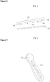
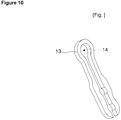
Figures 7 ,8 ,9 ,10 - are the perspective views of stoppers having cut-outs of various shapes. - The elements illustrated in the figures are numbered as follows:
- 1. Compressor
- 2. Casing
- 3. Cylinder
- 4. Piston
- 5. Cylinder head
- 6. Valve plate
- 7. Suction chamber
- 8. Discharge chamber
- 9. Inlet passage
- 10. Discharge passage
- 11. Suction valve
- 12. Discharge valve
- 13. Stopper
- 14. Cut-out
- 15. Protrusion
- In cooling devices, for example refrigerators, the circulation of the refrigerant fluid is provided by a compressor (1).
- The compressor (1) comprises a casing (2) wherein the components within are held, a cylinder (3) for pumping the refrigerant fluid, a piston (4) operating in the cylinder (3), a cylinder head (5) providing the circulation of the refrigerant fluid sucked and pumped by the reciprocation of the piston (4), a valve plate (6) disposed between the cylinder (3) and the cylinder head (5), a suction chamber (7) under the cylinder head (5) wherein the sucked refrigerant is accumulated, a discharge chamber (8) wherein the pumped refrigerant fluid accumulates, an inlet passage (9) and a discharge passage (10) situated on the valve plate (6) providing entry and exit of the refrigerant fluid in the suction and discharge chambers(7, 8) into/from the cylinder (3).
- The compressor (1) furthermore comprises a suction valve (11) situated on one side of the valve plate (6), that opens and closes the inlet passage (9) during the reciprocation of the piston (4) providing the refrigerant fluid to be aspirated into the cylinder (3) and a discharge valve (12) on the other side of the valve plate (6), that opens and closes the discharge passage (10) during the reciprocation of the piston (4) providing the refrigerant fluid to be discharged from the cylinder (3).
- The oil put into the casing provides the components in the compressor (1) to move with ease.
- The compressor (1) of the present invention comprises a stopper (13) that
- is situated on the discharge valve (12) at the valve plate (6),
- allowing the discharge valve (12) to open to a little extent by restraining the movement and thus maintaining the desired pressure in the discharge chamber (8) and
- has one or more cut-outs (14) providing to reduce the surface area that the discharge valve (12) contacts.
- The cut-out (14) is preferably shaped like a hole bored on the stopper (13) having various sizes (
Figures 7 ,8 ,9 ,10 ). - The cut-out (14) is made by hollowing out a part on the stopper (13) by perforating or drilling process.
- When the discharge valve (12) opens, it impacts on the surfaces of the stopper (13) excluding the cut-outs (14) and contact is maintained on the surface of the stopper (13) in an area less than the area of the discharge valve (12). Consequently, the adhesion force effect of the oil between the discharge valve (12) and the stopper (13) is reduced, minimizing the thermodynamic losses that occur in the discharge phase of the refrigerant cycle.
- When the piston (4) makes the compression stroke in the cylinder (3), the discharge valve (12) opens contacting the stopper (13) and when the piston (4) is in the sucking stroke, the discharge valve (12), released from the stopper (13), closes the discharge passage (10) in time since the contact surface therebetween is reduced due to the cut-outs (14) and accordingly the discharge gas leakage is prevented. The refrigerant fluid pumped into the discharge chamber (8) is not aspirated back into the cylinder (3) again and the compressor (1) capacity is enhanced since the discharge passage (10) is closed in time during the suction process of the refrigerant fluid pumped into the discharge chamber (8).
- By means of the cut-outs (14) formed on the stopper (13), the upper surface of the discharge valve (12) is furthermore provided to come into contact with the high pressure gas in the discharge chamber (8). Accordingly, gas pressure acts on the upper surface of the discharge valve (12) and the pressure imbalance between the two surfaces of the discharge valve (12) is reduced providing easier opening and closing.
- In the compressor (1) the rotational movement of the motor is transmitted to the piston (4) by means of the crank-connecting rod mechanism providing the reciprocative movement of the piston (4). By the movement of the piston (4) the process of sucking of the refrigerant fluid to/from the cylinder (3) is provided. The refrigerant fluid entering the cylinder (3) by means of the inlet passage (9) on the valve plate (6) and by the opening, closing suction valve (11), is compressed to maintain the desired pressure. The refrigerant fluid is delivered into the discharge chamber (8) by means of the discharge passage (10) on the valve plate (6) and the opening, closing discharge valve (12). When the discharge valve (12) opens and closes, the movement is restrained by the stopper (13) and the refrigerant fluid with the desired pressure is collected in the discharge chamber (8). The discharge valve (12) is released from the stopper (13) by retracting, closing on the discharge passage (10) just as the piston (4) starts the suction stroke by retracting and the refrigerant fluid in the discharge chamber (8) is prevented from receding back into the cylinder (3).
- In the present invention, the stopper (13) comprises one or more protrusions (15) that reduces the contact area of the discharge valve (12), thus providing the discharge valve (12), when opened, to only contact the ends thereof. In this embodiment, the discharge valve (12), when opened, only contacts the protrusions (15) on the stopper (13) and the adhesion force is reduced.
- More than one cut-out (14) is formed on the surface of the stopper (13) contacting the discharge valve (12) and the protrusions (15) are arranged between the cut-outs (14) (
Figure 6 ). - In the present invention, the contact area between the discharge valve (12) and the stopper (13) is reduced by means of the cut-out (14) and/or the protrusion (15) formed on the stopper (13). By means of reducing the contact area between the discharge valve (12) and the stopper (13), the adhesion force due to the oil therebetween is reduced in direct proportion. By means of reducing the adhesion force, the closing time of the discharge valve (12) is expedited and the compressed gas in the discharge chamber (8) is prevented from receding back into the cylinder (3) volume. A significant increase in the efficiency of the compressor (1) is provided by reducing the losses incurred in the delivery of the refrigerant gas, compressed to a certain pressure value in the cylinder (3) volume, to the cylinder head (5) discharge chamber (8).
Claims (1)
- A compressor (1) comprising a cylinder (3) for pumping the refrigerant fluid, a piston (4) operating in the cylinder (3), a cylinder head (5) providing the circulation of the refrigerant fluid sucked and pumped by the movement of the piston (4), a valve plate (6) disposed between the cylinder (3) and the cylinder head (5), a suction chamber (7) under the cylinder head (5) wherein the sucked refrigerant is collected, a discharge chamber (8) wherein the pumped refrigerant fluid accumulates, an inlet passage (9) and a discharge passage (10) situated on the valve plate (6) providing entry and exit of the refrigerant fluid in the suction and discharge chambers (7, 8) into/from the cylinder (3), a suction valve (11) situated on one side of the valve plate (6), that opens and closes the inlet passage (9) during the reciprocation of the piston (4) providing the refrigerant fluid to be aspirated into the cylinder (3) and an discharge valve (12) on the other side of the valve plate (6), that opens and closes the discharge passage (10) during the reciprocation of the piston (4) providing the refrigerant fluid to be discharged from the cylinder (3), and a stopper (13) that- is situated on the discharge valve (12) at the valve plate (6),- restraining the movement of the discharge valve (12), allowing the discharge valve (12) to be opened to a little extent and- comprising more than one cut-outs (14) providing to reduce the surface area that the discharge valve (12) contacts characterized by,- the stopper (13) further comprising one or more protrusions (15) that reduces the contact area of the discharge valve (12), providing the discharge valve (12), when opened, to only contact the protrusions (15) which are arranged between the cut-outs (14).
Applications Claiming Priority (2)
| Application Number | Priority Date | Filing Date | Title |
|---|---|---|---|
| TR200602129 | 2006-05-02 | ||
| PCT/EP2007/054162 WO2007128713A1 (en) | 2006-05-02 | 2007-04-27 | A compressor |
Publications (2)
| Publication Number | Publication Date |
|---|---|
| EP2013481A1 EP2013481A1 (en) | 2009-01-14 |
| EP2013481B1 true EP2013481B1 (en) | 2019-06-12 |
Family
ID=38344766
Family Applications (1)
| Application Number | Title | Priority Date | Filing Date |
|---|---|---|---|
| EP07728617.7A Active EP2013481B1 (en) | 2006-05-02 | 2007-04-27 | A compressor |
Country Status (4)
| Country | Link |
|---|---|
| EP (1) | EP2013481B1 (en) |
| CN (1) | CN101432524A (en) |
| BR (1) | BRPI0710968A2 (en) |
| WO (1) | WO2007128713A1 (en) |
Families Citing this family (3)
| Publication number | Priority date | Publication date | Assignee | Title |
|---|---|---|---|---|
| US10352308B2 (en) | 2012-12-18 | 2019-07-16 | Emerson Climate Technologies, Inc. | Reciprocating compressor with vapor injection system |
| CN105587598B (en) | 2014-11-10 | 2019-08-13 | Lg电子株式会社 | Reciprocating compressor |
| NO349349B1 (en) * | 2023-02-08 | 2025-12-15 | Heaten As | Piston compressor valve arrangement and method of use |
Citations (2)
| Publication number | Priority date | Publication date | Assignee | Title |
|---|---|---|---|---|
| JPS56173262U (en) * | 1980-05-24 | 1981-12-21 | ||
| US20030095883A1 (en) * | 2001-11-22 | 2003-05-22 | Knf Neuberger Gmbh | Oscillating restrictor |
Family Cites Families (9)
| Publication number | Priority date | Publication date | Assignee | Title |
|---|---|---|---|---|
| US1915694A (en) * | 1927-10-27 | 1933-06-27 | Ira H Reindel | Valve silencing construction |
| GB1500391A (en) * | 1974-05-13 | 1978-02-08 | Thermoking Corp | Gas compressor valve arrangement with wear resistance |
| GB1531122A (en) * | 1977-06-03 | 1978-11-01 | Trane Co | Valve plate having suction gas flow path |
| JPS5524276A (en) * | 1978-08-11 | 1980-02-21 | Arai Pump Mfg Co Ltd | Reed valve |
| US4723896A (en) * | 1987-04-30 | 1988-02-09 | White Consolidated Industries, Inc. | Compressor discharge valve assembly |
| EP0582712B1 (en) * | 1992-03-03 | 1997-02-05 | Matsushita Refrigeration Company | Hermetic compressor |
| JPH10339270A (en) * | 1997-06-05 | 1998-12-22 | Daewoo Electron Co Ltd | Valve combined body of compressor |
| JP2000087858A (en) * | 1998-09-16 | 2000-03-28 | Matsushita Refrig Co Ltd | Discharge valve device for compressor |
| KR100494527B1 (en) * | 2002-11-06 | 2005-06-10 | 삼성광주전자 주식회사 | Cylinder assembly for hermetic compressor |
-
2007
- 2007-04-27 EP EP07728617.7A patent/EP2013481B1/en active Active
- 2007-04-27 WO PCT/EP2007/054162 patent/WO2007128713A1/en not_active Ceased
- 2007-04-27 BR BRPI0710968-7A patent/BRPI0710968A2/en not_active Application Discontinuation
- 2007-04-27 CN CNA2007800156944A patent/CN101432524A/en active Pending
Patent Citations (2)
| Publication number | Priority date | Publication date | Assignee | Title |
|---|---|---|---|---|
| JPS56173262U (en) * | 1980-05-24 | 1981-12-21 | ||
| US20030095883A1 (en) * | 2001-11-22 | 2003-05-22 | Knf Neuberger Gmbh | Oscillating restrictor |
Also Published As
| Publication number | Publication date |
|---|---|
| CN101432524A (en) | 2009-05-13 |
| BRPI0710968A2 (en) | 2012-02-28 |
| EP2013481A1 (en) | 2009-01-14 |
| WO2007128713A1 (en) | 2007-11-15 |
Similar Documents
| Publication | Publication Date | Title |
|---|---|---|
| CA2069208C (en) | Refrigeration compressor having a contoured piston | |
| US20110103937A1 (en) | Discharge valve arrangement for a hermetic compressor | |
| US20060039808A1 (en) | Refrigerant compressor | |
| US20040047750A1 (en) | Reciprocating compressor | |
| US20070237663A1 (en) | Hermetic compressor | |
| KR100461232B1 (en) | Apparatus for compressing fluid | |
| EP3816442B1 (en) | Compressor and electronic device using same | |
| WO2007128713A1 (en) | A compressor | |
| CN100408851C (en) | hermetic compressor | |
| US20040086406A1 (en) | Cylinder assembly for hermetic compressor | |
| EP1957796B1 (en) | A compressor | |
| US20050129548A1 (en) | Suction valve and reciprocating compressor having the same | |
| EP1709330A1 (en) | Hermetic compressor | |
| EP2300715B1 (en) | A compressor with improved refrigerant flow performance | |
| JP6556372B1 (en) | Hermetic compressor and refrigeration cycle apparatus | |
| KR0134144Y1 (en) | Reciprocating compressor | |
| KR200317644Y1 (en) | Inlet muffler of a compressor | |
| KR100577824B1 (en) | Hermetic compressor | |
| JP2005214068A (en) | Hermetic reciprocating compressor | |
| KR20060047082A (en) | Valve Unit Structure of Automobile Compressor | |
| KR101576227B1 (en) | Valve assembly module of hermetic compressor | |
| KR20020037998A (en) | Structure for discharging active gas in hermetic compressor | |
| KR970002678Y1 (en) | Hermetic reciprocating compressor | |
| JP2007255245A (en) | Compressor | |
| KR20070051064A (en) | Hermetic compressor |
Legal Events
| Date | Code | Title | Description |
|---|---|---|---|
| PUAI | Public reference made under article 153(3) epc to a published international application that has entered the european phase |
Free format text: ORIGINAL CODE: 0009012 |
|
| 17P | Request for examination filed |
Effective date: 20081028 |
|
| AK | Designated contracting states |
Kind code of ref document: A1 Designated state(s): AT BE BG CH CY CZ DE DK EE ES FI FR GB GR HU IE IS IT LI LT LU LV MC MT NL PL PT RO SE SI SK TR |
|
| AX | Request for extension of the european patent |
Extension state: AL BA HR MK RS |
|
| 17Q | First examination report despatched |
Effective date: 20090407 |
|
| DAX | Request for extension of the european patent (deleted) | ||
| RIN1 | Information on inventor provided before grant (corrected) |
Inventor name: KARA, SERKAN Inventor name: ABDIK, BORA Inventor name: SAMUT, SEDAT Inventor name: AKBAS, FATIH Inventor name: YAROGLU, TOLGA |
|
| STAA | Information on the status of an ep patent application or granted ep patent |
Free format text: STATUS: EXAMINATION IS IN PROGRESS |
|
| GRAP | Despatch of communication of intention to grant a patent |
Free format text: ORIGINAL CODE: EPIDOSNIGR1 |
|
| STAA | Information on the status of an ep patent application or granted ep patent |
Free format text: STATUS: GRANT OF PATENT IS INTENDED |
|
| INTG | Intention to grant announced |
Effective date: 20190205 |
|
| GRAS | Grant fee paid |
Free format text: ORIGINAL CODE: EPIDOSNIGR3 |
|
| GRAA | (expected) grant |
Free format text: ORIGINAL CODE: 0009210 |
|
| STAA | Information on the status of an ep patent application or granted ep patent |
Free format text: STATUS: THE PATENT HAS BEEN GRANTED |
|
| AK | Designated contracting states |
Kind code of ref document: B1 Designated state(s): AT BE BG CH CY CZ DE DK EE ES FI FR GB GR HU IE IS IT LI LT LU LV MC MT NL PL PT RO SE SI SK TR |
|
| REG | Reference to a national code |
Ref country code: GB Ref legal event code: FG4D |
|
| REG | Reference to a national code |
Ref country code: CH Ref legal event code: EP |
|
| REG | Reference to a national code |
Ref country code: AT Ref legal event code: REF Ref document number: 1142903 Country of ref document: AT Kind code of ref document: T Effective date: 20190615 |
|
| REG | Reference to a national code |
Ref country code: DE Ref legal event code: R096 Ref document number: 602007058572 Country of ref document: DE |
|
| RAP2 | Party data changed (patent owner data changed or rights of a patent transferred) |
Owner name: ARCELIK ANONIM SIRKETI |
|
| REG | Reference to a national code |
Ref country code: IE Ref legal event code: FG4D |
|
| REG | Reference to a national code |
Ref country code: NL Ref legal event code: MP Effective date: 20190612 |
|
| REG | Reference to a national code |
Ref country code: LT Ref legal event code: MG4D |
|
| PG25 | Lapsed in a contracting state [announced via postgrant information from national office to epo] |
Ref country code: FI Free format text: LAPSE BECAUSE OF FAILURE TO SUBMIT A TRANSLATION OF THE DESCRIPTION OR TO PAY THE FEE WITHIN THE PRESCRIBED TIME-LIMIT Effective date: 20190612 Ref country code: LT Free format text: LAPSE BECAUSE OF FAILURE TO SUBMIT A TRANSLATION OF THE DESCRIPTION OR TO PAY THE FEE WITHIN THE PRESCRIBED TIME-LIMIT Effective date: 20190612 Ref country code: SE Free format text: LAPSE BECAUSE OF FAILURE TO SUBMIT A TRANSLATION OF THE DESCRIPTION OR TO PAY THE FEE WITHIN THE PRESCRIBED TIME-LIMIT Effective date: 20190612 Ref country code: ES Free format text: LAPSE BECAUSE OF FAILURE TO SUBMIT A TRANSLATION OF THE DESCRIPTION OR TO PAY THE FEE WITHIN THE PRESCRIBED TIME-LIMIT Effective date: 20190612 |
|
| PG25 | Lapsed in a contracting state [announced via postgrant information from national office to epo] |
Ref country code: BG Free format text: LAPSE BECAUSE OF FAILURE TO SUBMIT A TRANSLATION OF THE DESCRIPTION OR TO PAY THE FEE WITHIN THE PRESCRIBED TIME-LIMIT Effective date: 20190912 Ref country code: LV Free format text: LAPSE BECAUSE OF FAILURE TO SUBMIT A TRANSLATION OF THE DESCRIPTION OR TO PAY THE FEE WITHIN THE PRESCRIBED TIME-LIMIT Effective date: 20190612 Ref country code: GR Free format text: LAPSE BECAUSE OF FAILURE TO SUBMIT A TRANSLATION OF THE DESCRIPTION OR TO PAY THE FEE WITHIN THE PRESCRIBED TIME-LIMIT Effective date: 20190913 |
|
| REG | Reference to a national code |
Ref country code: AT Ref legal event code: MK05 Ref document number: 1142903 Country of ref document: AT Kind code of ref document: T Effective date: 20190612 |
|
| PG25 | Lapsed in a contracting state [announced via postgrant information from national office to epo] |
Ref country code: SK Free format text: LAPSE BECAUSE OF FAILURE TO SUBMIT A TRANSLATION OF THE DESCRIPTION OR TO PAY THE FEE WITHIN THE PRESCRIBED TIME-LIMIT Effective date: 20190612 Ref country code: RO Free format text: LAPSE BECAUSE OF FAILURE TO SUBMIT A TRANSLATION OF THE DESCRIPTION OR TO PAY THE FEE WITHIN THE PRESCRIBED TIME-LIMIT Effective date: 20190612 Ref country code: EE Free format text: LAPSE BECAUSE OF FAILURE TO SUBMIT A TRANSLATION OF THE DESCRIPTION OR TO PAY THE FEE WITHIN THE PRESCRIBED TIME-LIMIT Effective date: 20190612 Ref country code: PT Free format text: LAPSE BECAUSE OF FAILURE TO SUBMIT A TRANSLATION OF THE DESCRIPTION OR TO PAY THE FEE WITHIN THE PRESCRIBED TIME-LIMIT Effective date: 20191014 Ref country code: AT Free format text: LAPSE BECAUSE OF FAILURE TO SUBMIT A TRANSLATION OF THE DESCRIPTION OR TO PAY THE FEE WITHIN THE PRESCRIBED TIME-LIMIT Effective date: 20190612 Ref country code: CZ Free format text: LAPSE BECAUSE OF FAILURE TO SUBMIT A TRANSLATION OF THE DESCRIPTION OR TO PAY THE FEE WITHIN THE PRESCRIBED TIME-LIMIT Effective date: 20190612 Ref country code: NL Free format text: LAPSE BECAUSE OF FAILURE TO SUBMIT A TRANSLATION OF THE DESCRIPTION OR TO PAY THE FEE WITHIN THE PRESCRIBED TIME-LIMIT Effective date: 20190612 |
|
| PG25 | Lapsed in a contracting state [announced via postgrant information from national office to epo] |
Ref country code: IT Free format text: LAPSE BECAUSE OF FAILURE TO SUBMIT A TRANSLATION OF THE DESCRIPTION OR TO PAY THE FEE WITHIN THE PRESCRIBED TIME-LIMIT Effective date: 20190612 Ref country code: IS Free format text: LAPSE BECAUSE OF FAILURE TO SUBMIT A TRANSLATION OF THE DESCRIPTION OR TO PAY THE FEE WITHIN THE PRESCRIBED TIME-LIMIT Effective date: 20191012 |
|
| REG | Reference to a national code |
Ref country code: DE Ref legal event code: R097 Ref document number: 602007058572 Country of ref document: DE |
|
| PLBE | No opposition filed within time limit |
Free format text: ORIGINAL CODE: 0009261 |
|
| STAA | Information on the status of an ep patent application or granted ep patent |
Free format text: STATUS: NO OPPOSITION FILED WITHIN TIME LIMIT |
|
| PG25 | Lapsed in a contracting state [announced via postgrant information from national office to epo] |
Ref country code: PL Free format text: LAPSE BECAUSE OF FAILURE TO SUBMIT A TRANSLATION OF THE DESCRIPTION OR TO PAY THE FEE WITHIN THE PRESCRIBED TIME-LIMIT Effective date: 20190612 Ref country code: DK Free format text: LAPSE BECAUSE OF FAILURE TO SUBMIT A TRANSLATION OF THE DESCRIPTION OR TO PAY THE FEE WITHIN THE PRESCRIBED TIME-LIMIT Effective date: 20190612 |
|
| 26N | No opposition filed |
Effective date: 20200313 |
|
| PG25 | Lapsed in a contracting state [announced via postgrant information from national office to epo] |
Ref country code: IS Free format text: LAPSE BECAUSE OF FAILURE TO SUBMIT A TRANSLATION OF THE DESCRIPTION OR TO PAY THE FEE WITHIN THE PRESCRIBED TIME-LIMIT Effective date: 20200224 Ref country code: SI Free format text: LAPSE BECAUSE OF FAILURE TO SUBMIT A TRANSLATION OF THE DESCRIPTION OR TO PAY THE FEE WITHIN THE PRESCRIBED TIME-LIMIT Effective date: 20190612 |
|
| PG2D | Information on lapse in contracting state deleted |
Ref country code: IS |
|
| PG25 | Lapsed in a contracting state [announced via postgrant information from national office to epo] |
Ref country code: IS Free format text: LAPSE BECAUSE OF FAILURE TO SUBMIT A TRANSLATION OF THE DESCRIPTION OR TO PAY THE FEE WITHIN THE PRESCRIBED TIME-LIMIT Effective date: 20191112 |
|
| REG | Reference to a national code |
Ref country code: DE Ref legal event code: R119 Ref document number: 602007058572 Country of ref document: DE |
|
| PG25 | Lapsed in a contracting state [announced via postgrant information from national office to epo] |
Ref country code: MC Free format text: LAPSE BECAUSE OF FAILURE TO SUBMIT A TRANSLATION OF THE DESCRIPTION OR TO PAY THE FEE WITHIN THE PRESCRIBED TIME-LIMIT Effective date: 20190612 |
|
| REG | Reference to a national code |
Ref country code: CH Ref legal event code: PL |
|
| PG25 | Lapsed in a contracting state [announced via postgrant information from national office to epo] |
Ref country code: FR Free format text: LAPSE BECAUSE OF NON-PAYMENT OF DUE FEES Effective date: 20200430 Ref country code: DE Free format text: LAPSE BECAUSE OF NON-PAYMENT OF DUE FEES Effective date: 20201103 Ref country code: LI Free format text: LAPSE BECAUSE OF NON-PAYMENT OF DUE FEES Effective date: 20200430 Ref country code: LU Free format text: LAPSE BECAUSE OF NON-PAYMENT OF DUE FEES Effective date: 20200427 Ref country code: CH Free format text: LAPSE BECAUSE OF NON-PAYMENT OF DUE FEES Effective date: 20200430 |
|
| REG | Reference to a national code |
Ref country code: BE Ref legal event code: MM Effective date: 20200430 |
|
| PG25 | Lapsed in a contracting state [announced via postgrant information from national office to epo] |
Ref country code: BE Free format text: LAPSE BECAUSE OF NON-PAYMENT OF DUE FEES Effective date: 20200430 |
|
| PG25 | Lapsed in a contracting state [announced via postgrant information from national office to epo] |
Ref country code: IE Free format text: LAPSE BECAUSE OF NON-PAYMENT OF DUE FEES Effective date: 20200427 |
|
| PG25 | Lapsed in a contracting state [announced via postgrant information from national office to epo] |
Ref country code: MT Free format text: LAPSE BECAUSE OF FAILURE TO SUBMIT A TRANSLATION OF THE DESCRIPTION OR TO PAY THE FEE WITHIN THE PRESCRIBED TIME-LIMIT Effective date: 20190612 Ref country code: CY Free format text: LAPSE BECAUSE OF FAILURE TO SUBMIT A TRANSLATION OF THE DESCRIPTION OR TO PAY THE FEE WITHIN THE PRESCRIBED TIME-LIMIT Effective date: 20190612 |
|
| PGFP | Annual fee paid to national office [announced via postgrant information from national office to epo] |
Ref country code: TR Payment date: 20250414 Year of fee payment: 19 |
|
| PGFP | Annual fee paid to national office [announced via postgrant information from national office to epo] |
Ref country code: GB Payment date: 20260306 Year of fee payment: 20 |