EP2013443B1 - Apparatus and method for severing a wellbore tubular - Google Patents
Apparatus and method for severing a wellbore tubular Download PDFInfo
- Publication number
- EP2013443B1 EP2013443B1 EP20060820703 EP06820703A EP2013443B1 EP 2013443 B1 EP2013443 B1 EP 2013443B1 EP 20060820703 EP20060820703 EP 20060820703 EP 06820703 A EP06820703 A EP 06820703A EP 2013443 B1 EP2013443 B1 EP 2013443B1
- Authority
- EP
- European Patent Office
- Prior art keywords
- blade
- projection
- wellbore tubular
- tubular
- cutting surfaces
- Prior art date
- Legal status (The legal status is an assumption and is not a legal conclusion. Google has not performed a legal analysis and makes no representation as to the accuracy of the status listed.)
- Active
Links
Images


Classifications
-
- E—FIXED CONSTRUCTIONS
- E21—EARTH OR ROCK DRILLING; MINING
- E21B—EARTH OR ROCK DRILLING; OBTAINING OIL, GAS, WATER, SOLUBLE OR MELTABLE MATERIALS OR A SLURRY OF MINERALS FROM WELLS
- E21B33/00—Sealing or packing boreholes or wells
- E21B33/02—Surface sealing or packing
- E21B33/03—Well heads; Setting-up thereof
- E21B33/06—Blow-out preventers, i.e. apparatus closing around a drill pipe, e.g. annular blow-out preventers
- E21B33/061—Ram-type blow-out preventers, e.g. with pivoting rams
- E21B33/062—Ram-type blow-out preventers, e.g. with pivoting rams with sliding rams
- E21B33/063—Ram-type blow-out preventers, e.g. with pivoting rams with sliding rams for shearing drill pipes
-
- Y—GENERAL TAGGING OF NEW TECHNOLOGICAL DEVELOPMENTS; GENERAL TAGGING OF CROSS-SECTIONAL TECHNOLOGIES SPANNING OVER SEVERAL SECTIONS OF THE IPC; TECHNICAL SUBJECTS COVERED BY FORMER USPC CROSS-REFERENCE ART COLLECTIONS [XRACs] AND DIGESTS
- Y10—TECHNICAL SUBJECTS COVERED BY FORMER USPC
- Y10T—TECHNICAL SUBJECTS COVERED BY FORMER US CLASSIFICATION
- Y10T428/00—Stock material or miscellaneous articles
- Y10T428/24—Structurally defined web or sheet [e.g., overall dimension, etc.]
- Y10T428/24777—Edge feature
-
- Y—GENERAL TAGGING OF NEW TECHNOLOGICAL DEVELOPMENTS; GENERAL TAGGING OF CROSS-SECTIONAL TECHNOLOGIES SPANNING OVER SEVERAL SECTIONS OF THE IPC; TECHNICAL SUBJECTS COVERED BY FORMER USPC CROSS-REFERENCE ART COLLECTIONS [XRACs] AND DIGESTS
- Y10—TECHNICAL SUBJECTS COVERED BY FORMER USPC
- Y10T—TECHNICAL SUBJECTS COVERED BY FORMER US CLASSIFICATION
- Y10T83/00—Cutting
- Y10T83/04—Processes
- Y10T83/0581—Cutting part way through from opposite sides of work
-
- Y—GENERAL TAGGING OF NEW TECHNOLOGICAL DEVELOPMENTS; GENERAL TAGGING OF CROSS-SECTIONAL TECHNOLOGIES SPANNING OVER SEVERAL SECTIONS OF THE IPC; TECHNICAL SUBJECTS COVERED BY FORMER USPC CROSS-REFERENCE ART COLLECTIONS [XRACs] AND DIGESTS
- Y10—TECHNICAL SUBJECTS COVERED BY FORMER USPC
- Y10T—TECHNICAL SUBJECTS COVERED BY FORMER US CLASSIFICATION
- Y10T83/00—Cutting
- Y10T83/04—Processes
- Y10T83/0596—Cutting wall of hollow work
-
- Y—GENERAL TAGGING OF NEW TECHNOLOGICAL DEVELOPMENTS; GENERAL TAGGING OF CROSS-SECTIONAL TECHNOLOGIES SPANNING OVER SEVERAL SECTIONS OF THE IPC; TECHNICAL SUBJECTS COVERED BY FORMER USPC CROSS-REFERENCE ART COLLECTIONS [XRACs] AND DIGESTS
- Y10—TECHNICAL SUBJECTS COVERED BY FORMER USPC
- Y10T—TECHNICAL SUBJECTS COVERED BY FORMER US CLASSIFICATION
- Y10T83/00—Cutting
- Y10T83/748—With work immobilizer
- Y10T83/7487—Means to clamp work
- Y10T83/7493—Combined with, peculiarly related to, other element
- Y10T83/75—With or to tool guide
-
- Y—GENERAL TAGGING OF NEW TECHNOLOGICAL DEVELOPMENTS; GENERAL TAGGING OF CROSS-SECTIONAL TECHNOLOGIES SPANNING OVER SEVERAL SECTIONS OF THE IPC; TECHNICAL SUBJECTS COVERED BY FORMER USPC CROSS-REFERENCE ART COLLECTIONS [XRACs] AND DIGESTS
- Y10—TECHNICAL SUBJECTS COVERED BY FORMER USPC
- Y10T—TECHNICAL SUBJECTS COVERED BY FORMER US CLASSIFICATION
- Y10T83/00—Cutting
- Y10T83/929—Tool or tool with support
- Y10T83/9411—Cutting couple type
- Y10T83/9447—Shear type
Definitions
- the present invention relates to an apparatus for severing a wellbore tubular, to a blade for use in such apparatus, to a blowout preventer comprising the apparatus, and to a method of severing a wellbore tubular.
- blowout preventers and tubular-shearing blades for blowout preventer bonnets.
- Typical blowout preventers have selectively actuatable rams in oppositely disposed bonnets secured to a main body.
- the rams are either pipe rams (to contact, engage, and encompass pipe and/or tools to seal a wellbore) or shear rams (to contact and physically shear a tubular, casing, pipe or tool used in wellbore operations).
- Rams are usually positioned opposite each other on either side of the main body and can, upon activation and subsequent shearing of a tubular, seal against each other at a centre of the main body over a centre of a wellbore.
- Typical rams include a ram block on which parts, e.g. seals and/or cutting blades, are releasably secured.
- blowout preventer which can effectively and efficiently shear tubulars, e.g. tubulars used in wellbore operations, including relatively large tubulars such as casing, drill collars, and drill pipe tool joints.
- tubular shearing systems a tool joint is located so that shearing rams do not encounter the tool joint, but shear only a relatively smaller portion of the tubular.
- One problem with such systems is that proper location takes time and, if a tool joint is improperly located, no or ineffectual shearing may result.
- US-A-4 537 250 discloses a ram-type shearing apparatus for a wellhead having a body with a vertical bore therethrough and aligned, opposed ram guideways extending outward in the body from the bore.
- a ram assembly is provided in each of the guideways, and each of the ram assemblies has a ram body with a shearing blade on the face of the ram and means for moving the ram inward and outward in the guideway.
- a cutting edge of the upper shear blade and the face of the ram assembly below the upper shear blade are concave to support the string sufficiently during shearing to constrain the string below the upper shear blade as it is sheared to a shape suitable for receiving an overshot type of retrieving tool and to allow flow therein.
- the lower shear blade has at least one node extending toward the upper shear blade so that when a pipe is being sheared the node engages and penetrates the pipe prior to other shearing of the pipe to thereby reduce the force used for such shearing
- US-A-5 217 073 discloses a cut-and-close device for pressure pipes in production and supply installations for gaseous and liquid media includes a two-piece clamping block.
- a pipe-cutting and pipe-closing plate is driven into said clamping block by means of a propelling charge and a piston, both of which form part of a drive unit.
- the clamping block is divided in the middle of its circular opening into a rear part and a front part.
- the rear part and the front part can be screwed together.
- the rear part and the front part have rectangular slits on the inside.
- the front part also possesses a slot opening large enough for a shearing plate.
- the shearing plate runs in guide grooves of a connector bolted to the front part of the clamping block.
- the conductor is attached to the drive unit consisting of a pressure cylinder, a piston, and a cartridge furnishing a remotely triggered propelling charge.
- an apparatus for severing a wellbore tubular which apparatus comprises at least one blade having a blade width for shearing across a longitudinal axis of said wellbore tubular, characterised in that said at least one blade comprises a single projection having a pointed end and a base end wider than said pointed end but narrower than said blade width, said pointed end and said base end being joined by projection cutting surfaces, said at least one blade having an adjacent cutting surface on either side of said base end, the arrangement being such that, in use, when said at least one blade is moved in a direction toward said wellbore tubular, firstly said pointed end punctures the wall of said wellbore tubular, further movement of said at least one blade in said direction causes progressive cutting of said wall by said projection cutting surfaces so as to reduce the structural strength of said wellbore tubular and leaving a portion of said wall remaining to be severed, and secondly said portion of the wellbore tubular is severed by said adjacent cutting surfaces on either side of said base end of said single projection.
- the at least one blade comprises a single projection
- the projection may have a portion of gradually increasing width whereby, in use, the projection penetrates and punctures the wall of the wellbore tubular and respective surfaces on opposite sides of the portion shear the tubular in opposite circumferential directions simultaneously.
- a blowout preventer comprising an apparatus as aforesaid.
- a blowout preventer 10 has a body 12 with a vertical bore 14 extending therethrough.
- a tubular, e.g. part of a drill string D passes through the bore 14.
- the body 12 has a lower flange 16 and an upper flange 18 for connecting the blowout preventer 10 in a wellhead stack.
- Ram guideways 20 and 22 extend outwardly from opposite sides of the bore 14.
- Ram assemblies of the blowout preventer 10 include first and second rams 24 and 26 which are positioned in guideways 20 and 22, respectively.
- Reciprocating apparatus such as actuators 28, are provided to move or extend the rams in response to fluid pressure into the bore 14 for shearing the portion of the drill string D which extends through the bore and for retracting the rams from the bore.
- the actuators 28 each include a piston 30 in a cylinder 32 and a rod 34 connecting between the piston and the ram which it is to move and are suitably connected to body 12 as shown. Suitable apparatus is provided to deliver fluid under pressure to opposite sides of piston 30.
- An upper cutting blade 36 (any blade according to the present invention) is on the ram 24 and a lower cutting blade 38 (any blade according to the present invention) is on the ram 26.
- the cutting blades 36 and 38 are positioned so that the cutting edge of the blade 38 passes just below the cutting edge of the blade 36 in shearing of a section of a tubular, e.g. the drillstring D.
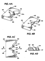
- Figs. 2A - 2D show a blade 50 according to the present invention which has a body 52 with a base 57 and a front face 54.
- the front face 54 has two inclined portions 61, 62 and a projection 60 that projects from the front face 54 between the two inclined portions 61, 62. Edges 56, 58 are at ends of the inclined portions 61, 62, respectively.
- the projection 60 has two inclined faces 63, 64 which meet at a central edge 65.
- An angle 68 between the faces 63, 64 may be any desired angle and, in certain aspects, ranges between 30 degrees to ninety degrees and, in certain particular aspects, is 30 degrees, 60 degrees, or 90 degrees.
- the cutting surfaces are sloped from the vertical and in one particular aspect, as shown in Fig. 2D , the two inclined portions 61, 62 are at an angle of 20 degrees from the vertical.
- the angle for any cutting surface of any blade according to the present invention ranges between 20 degrees and 60 degrees; and, in certain aspects, the angle is 20 degrees, 45 degrees, or 60 degrees.
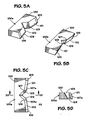
- Figs. 3A - 3D show a blade 70 according to the present invention which has a body 72 with a base 77, two opposed inclined faces 81, 82 and a projection 80 between the two inclined faces 81, 82.
- the projection 80 has two inclined faces 83, 84 which meet at a central edge 85.
- Inclined end portions 76, 78 are at ends of the faces 81, 82 respectively.
- Figs. 4A - 4D show a blade 90 with a body 99; opposed inclined faces 91, 92; opposed inclined faces 93, 94; and inclined end portions 95, 96. Projections 97, 98 are formed between faces 91, 93 and 94, 92, respectively.
- the blade 90 has a base 90a.
- Figs. 5A - 5D show a blade 100 with a body 100a; opposed inclined faces 101, 102; opposed inclined faces 103, 104; and opposed inclined end portions 105, 106.
- Projections 107, 108 are formed between faces 101, 103 and 104, 102, respectively.
- the blade 100 has a base 109.
- Projection 107 has an edge 107a and projection 108 has an edge 108a.
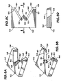
- Figs. 6A - 6D show a blade 110 with a body 110a, two inclined faces 111, 112; two opposed inclined faces 113, 114; inclined end portions 115, 116; a central semicircular inclined face 117; and a base 110b.
- Projections 118, 119 are formed between faces 111, 113 and 114, 112, respectively.
- Projection 118 has an edge 118a and projection 119 has an edge 119a.
- Figs. 7A - 7D show a blade 120 which has a body 122; a base 124; opposed inclined faces 126, 128; inclined faces 132, 134; inclined end portions 136, 138; and a semicircular inclined face 130.
- a serrated cutting surface 125 extends around a lower edge 127 of the face 130 and extends partially onto the faces 126, 128. As shown the serrations of the surface 125 have pointed tips 129; but, optionally, these tips may be rounded off.
- the faces 126, 132 are at an angle to each other forming a projection 131 with an edge 135.
- the faces 128, 134 are at an angle to each other forming the projection 133 with an edge 137.
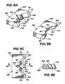
- Figs. 8A - 8D show a blade 140 according to the present invention which has a body 142; a base 144; opposed inclined faces 146, 148; a projection 150 between the faces 146, 148; and inclined end portions 156, 158.
- the projection 150 has inclined faces 151, 152 and a center face 153.
- a projection 155 is formed between the faces 156, 146 having an edge 154.
- a projection 157 is formed between the faces 148, 158 having an edge 159.
- the projection 150 is rounded off.
- Figs. 9A - 9D show a blade 160 which has a body 162; a base 164; opposed inclined faces 172, 173; inclined end portions 171, 174; projections 181, 182; and a recess 180 formed between the projections 181, 182.
- a projection 161 with an edge 163 is formed between the face 172 and the end portion 171.
- a projection 165 with an edge 167 is formed between the face 173 and the end portion 174.
- the projection 181 has inclined faces 183, 185 and an inclined center portion 184.
- the projection 182 has inclined faces 186, 188 and an inclined center portion 187.
- the projections 181, 182 are rounded off.
- Fig. 10 shows an apparatus 200 for severing a tubular (e.g., but not limited to, drill pipe, drill collar, casing, riser, tubing, and drill pipe tool joints - as is true and can be accomplished with any apparatus herein according to the present invention and with any blade or blades according to the present invention).
- the apparatus 200 has two alternately movable sets of rams 201, 202 and 203, 204.
- each ram 201, 202 has a plurality of spaced-apart puncturing points (or projections) 206 which make a series of corresponding spaced-apart holes in a tubular, thereby weakening the tubular and facilitating its complete shearing by blades 208 (any according to the present invention) of the rams 203, 204.
- Fig. 11 shows an apparatus 220 according to the present invention which has two sets of movable rams 221, 222 and 223, 224.
- Rams 221, 222 have flat faces 228 which are used to flatten a tubular 229 ("flatten" means make non-round to any extent as compared to the original round shape of the tubular 229 and includes, but it not limited to, a substantially or totally flattened tubular), e.g. as shown by the dotted line in Fig. 11 .
- the tubular 229 is completely severed by blades 225, 226 on the rams 223, 224, respectively.
- the blades 225, 226 may be any blade according to the present invention.
- Fig. 12 illustrates a method for severing a tubular 230 by either applying tension T to the tubular lengthwise with a tension applying apparatus TA, shown schematically (see arrows T) or by applying compression to it with a compression applying apparatus CA shown schematically (see arrows C).
- Ram apparatuses 231, 232 with blades 233, 234 respectively of a blowout preventer 235 are movable to sever the tubular 230.
- a tensioning step or steps and/or a compression step or steps may be used with any method according to the present invention, including but not limited to, methods as illustrated in Figs. 10 - 15 .
- Fig. 13 illustrates a method according to the present invention in which torque is applied to a tubular 240 while it is severed with blades 242, 243 (any blade or blades according to the present invention) of movable ram apparatuses 244, 245 of a blowout preventer 246.
- Rotation of the tubular 240 can be accomplished by any suitable rotating apparatus above, adjacent, and/or below the tubular, e.g. an apparatus RA (shown schematically in Fig. 13 ).
- a torquing step or steps may be used with any method according to the present invention.
- Fig. 14 illustrates a method according to the present invention for either severing a tubular 254 with blades 255 on movable rams 256 within a blowout preventer apparatus 250 using controlled explosive charges 252 in or on movable bodies 253; or a method for weakening a tubular at specific desired locations to facilitate complete severing of the tubular by blade(s) according to the present invention.
- the charges 252 are mounted on the blades 255 or on the rams 256.
- One, two, three, four or more charges may be used. Any blade according to the present invention may be used.
- FIGs. 15A - 15H illustrate a method according to the present invention using a blowout preventer 300 (depicted schematically, Fig. 15B ) according to the present invention (e.g. as any disclosed herein) with movable rams R (shown schematically, Fig. 15B ) with blades 301, 302 (blade 301 like blade 302; blade 302 inverted with respect to blade 301 - as may be the case with any two blades of any apparatus disclosed herein).
- Each blade 301, 302 has a body 304 and a central projection 310 with a pointed member 312 and cutting portions 313, 314.
- Each projection 310 has cutting surfaces 310a and 310b.
- the cutting surfaces are sloped from the vertical and the projections 310 have cutting surfaces at an angle to each other.
- the rams R move the blades so that, initially, the projections 310 contact and puncture a tubular T (e.g. casing, drill pipe, tool joints, drill collars, etc.) and then, following movement of the projections into the tubular T and cutting of the tubular T by the projections 310 and the cutting portions 313, 314, complete severing of the tubular T.
- the projections 310 are diametrically opposed so that the outermost point of the projections (and then the remainder of the projections) push against each other facilitating puncturing of the tubular and then severing of the tubular.
- This use of dual opposed puncturing projections also serves to maintain the tubular is a desired location within the blowout preventer 300 during severing so that puncturing and severing proceed with the blades 301, 302 maintained in a desired relation with respect to the tubular T.
- FIG. 15B illustrates initial entry of the points 312 into the tubular T.
- Fig. 15D illustrates further inward progress of the points 312 and further separation of the tubular portions T1, T2 and T3, T4.
- the cutting surfaces 313 and 314 begin to cut the tubular T.
- the projections 310 cut an amount of the tubular T and the cutting surfaces 313, 314 (and the projections 310 as they progress through the tubular) need cut only the remaining portion of the tubular T to effect complete severing of the tubular T. In certain aspects, and depending on the size of the tubular, the projections 310 can cut the entire tubular.
- FIG. 15G shows the tubular T completely severed.
- only one blade 301 or 302 is used and the other blade has no projection or projections.
- one blade be inverted with respect to an opposite blade.
- cutting surfaces adjacent a cutting projection either cut no tubular at all or only need cut only a fraction of a total wall thickness, circumference of a tubular (unlike, e.g., certain prior "V shear” or "V-shaped” blades in which each cutting surface cuts a much larger portion of a tubular).
- any blade according to the present invention or any prior blade or part thereof, and/or cutting surfaces thereof, and/or top and/or bottom thereof, and/or a tubular-puncturing part thereof with a low friction coating, e.g., but not limited to, polytetrafluoroethylene coating, electroless nickel coating, and/or titanium/nickel coating, including but not limited to, low friction coatings applied by a physical vapor deposition ("PVD") process.
- PVD physical vapor deposition
- Such coatings are shown, e.g., as a coating 69 ( Fig. 2A ) and a coating 209 ( Fig. 10 ) and as a coating 79 ( Fig. 3A ) on the top of a blade and as a coating 75 ( Fig. 3A ) on the bottom of a blade, applied by any suitable method or process.
- These coatings may be applied to any suitable known thickness for the application of low friction coatings.
Landscapes
- Geology (AREA)
- Life Sciences & Earth Sciences (AREA)
- Engineering & Computer Science (AREA)
- Mining & Mineral Resources (AREA)
- Environmental & Geological Engineering (AREA)
- Fluid Mechanics (AREA)
- General Life Sciences & Earth Sciences (AREA)
- Geochemistry & Mineralogy (AREA)
- Physics & Mathematics (AREA)
- Perforating, Stamping-Out Or Severing By Means Other Than Cutting (AREA)
- Superconductors And Manufacturing Methods Therefor (AREA)
- Lubricants (AREA)
- Shearing Machines (AREA)
- Processing Of Stones Or Stones Resemblance Materials (AREA)
- Bidet-Like Cleaning Device And Other Flush Toilet Accessories (AREA)
- Pharmaceuticals Containing Other Organic And Inorganic Compounds (AREA)
- Lining Or Joining Of Plastics Or The Like (AREA)
- Processing Of Solid Wastes (AREA)
- Sawing (AREA)
- Scissors And Nippers (AREA)
- Turning (AREA)
- Sampling And Sample Adjustment (AREA)
- Ceramic Products (AREA)
Priority Applications (6)
| Application Number | Priority Date | Filing Date | Title |
|---|---|---|---|
| EP20110180811 EP2400110B1 (en) | 2006-04-25 | 2006-12-27 | Apparatus and method for severing a wellbore tubular |
| PL11180788T PL2400109T3 (pl) | 2006-04-25 | 2006-12-27 | Urządzenie i sposób odcinania elementu rurowego odwiertu |
| PL11180811T PL2400110T3 (pl) | 2006-04-25 | 2006-12-27 | Sposób i urządzenie do przecinania rury wiertniczej |
| PL06820703T PL2013443T3 (pl) | 2006-04-25 | 2006-12-27 | Urządzenie i sposób odcinania elementu rurowego odwiertu |
| EP20110180788 EP2400109B1 (en) | 2006-04-25 | 2006-12-27 | Apparatus and method for severing a wellbore tubular |
| EP20110168306 EP2363572A1 (en) | 2006-04-25 | 2006-12-27 | Apparatus and method for severing a wellbore tubular |
Applications Claiming Priority (2)
| Application Number | Priority Date | Filing Date | Title |
|---|---|---|---|
| US11/411,203 US7367396B2 (en) | 2006-04-25 | 2006-04-25 | Blowout preventers and methods of use |
| PCT/GB2006/050478 WO2007122365A1 (en) | 2006-04-25 | 2006-12-27 | Apparatus and method for severing a wellbore tubular |
Related Child Applications (1)
| Application Number | Title | Priority Date | Filing Date |
|---|---|---|---|
| EP20110180788 Division EP2400109B1 (en) | 2006-04-25 | 2006-12-27 | Apparatus and method for severing a wellbore tubular |
Publications (2)
| Publication Number | Publication Date |
|---|---|
| EP2013443A1 EP2013443A1 (en) | 2009-01-14 |
| EP2013443B1 true EP2013443B1 (en) | 2011-06-01 |
Family
ID=37835262
Family Applications (4)
| Application Number | Title | Priority Date | Filing Date |
|---|---|---|---|
| EP20060820703 Active EP2013443B1 (en) | 2006-04-25 | 2006-12-27 | Apparatus and method for severing a wellbore tubular |
| EP20110168306 Withdrawn EP2363572A1 (en) | 2006-04-25 | 2006-12-27 | Apparatus and method for severing a wellbore tubular |
| EP20110180788 Active EP2400109B1 (en) | 2006-04-25 | 2006-12-27 | Apparatus and method for severing a wellbore tubular |
| EP20110180811 Active EP2400110B1 (en) | 2006-04-25 | 2006-12-27 | Apparatus and method for severing a wellbore tubular |
Family Applications After (3)
| Application Number | Title | Priority Date | Filing Date |
|---|---|---|---|
| EP20110168306 Withdrawn EP2363572A1 (en) | 2006-04-25 | 2006-12-27 | Apparatus and method for severing a wellbore tubular |
| EP20110180788 Active EP2400109B1 (en) | 2006-04-25 | 2006-12-27 | Apparatus and method for severing a wellbore tubular |
| EP20110180811 Active EP2400110B1 (en) | 2006-04-25 | 2006-12-27 | Apparatus and method for severing a wellbore tubular |
Country Status (12)
| Country | Link |
|---|---|
| US (5) | US7367396B2 (pl) |
| EP (4) | EP2013443B1 (pl) |
| CN (1) | CN101427003B (pl) |
| AT (1) | ATE511596T1 (pl) |
| AU (1) | AU2006342770A1 (pl) |
| BR (1) | BRPI0621572A2 (pl) |
| CA (3) | CA2747138C (pl) |
| DK (2) | DK2400109T3 (pl) |
| NO (3) | NO340135B1 (pl) |
| PL (3) | PL2400109T3 (pl) |
| RU (1) | RU2401935C2 (pl) |
| WO (1) | WO2007122365A1 (pl) |
Cited By (4)
| Publication number | Priority date | Publication date | Assignee | Title |
|---|---|---|---|---|
| US8066070B2 (en) | 2006-04-25 | 2011-11-29 | National Oilwell Varco, L.P. | Blowout preventers and methods of use |
| US8424607B2 (en) | 2006-04-25 | 2013-04-23 | National Oilwell Varco, L.P. | System and method for severing a tubular |
| US8720565B2 (en) | 2006-04-25 | 2014-05-13 | National Oilwell Varco, L.P. | Tubular severing system and method of using same |
| US8720564B2 (en) | 2006-04-25 | 2014-05-13 | National Oilwell Varco, L.P. | Tubular severing system and method of using same |
Families Citing this family (94)
| Publication number | Priority date | Publication date | Assignee | Title |
|---|---|---|---|---|
| US20080105436A1 (en) * | 2006-11-02 | 2008-05-08 | Schlumberger Technology Corporation | Cutter Assembly |
| US20120291606A1 (en) * | 2007-05-16 | 2012-11-22 | Khoury John J | Tubular cutting apparatus |
| US20080282857A1 (en) * | 2007-05-16 | 2008-11-20 | Khoury John J | Cutting machine for use in removing damaged oilfield rigs and equipment located in offshore waters, and method of using same |
| US20170282263A1 (en) * | 2007-05-16 | 2017-10-05 | John J. Khoury | Tubular cutting apparatus |
| CN101519952A (zh) * | 2008-02-25 | 2009-09-02 | 普拉德研究及开发股份有限公司 | 刀具组件 |
| US8844898B2 (en) | 2009-03-31 | 2014-09-30 | National Oilwell Varco, L.P. | Blowout preventer with ram socketing |
| US8567490B2 (en) | 2009-06-19 | 2013-10-29 | National Oilwell Varco, L.P. | Shear seal blowout preventer |
| US8783361B2 (en) | 2011-02-24 | 2014-07-22 | Foro Energy, Inc. | Laser assisted blowout preventer and methods of use |
| US8720584B2 (en) | 2011-02-24 | 2014-05-13 | Foro Energy, Inc. | Laser assisted system for controlling deep water drilling emergency situations |
| US8783360B2 (en) | 2011-02-24 | 2014-07-22 | Foro Energy, Inc. | Laser assisted riser disconnect and method of use |
| US8684088B2 (en) | 2011-02-24 | 2014-04-01 | Foro Energy, Inc. | Shear laser module and method of retrofitting and use |
| US8166993B2 (en) * | 2009-09-03 | 2012-05-01 | Hydril Usa Manufacturing Llc | Method and systems for using a shim plate for increased strength |
| US8833220B1 (en) * | 2009-09-16 | 2014-09-16 | II Woodrow A. Powers | Knife assembly for a trimming machine |
| US8573598B2 (en) * | 2009-09-17 | 2013-11-05 | Diamond Power International, Inc. | Sootblower isolation wall box |
| US8225857B2 (en) * | 2009-11-25 | 2012-07-24 | Hydril Usa Manufacturing Llc | Breech lock mechanisms for blowout preventer and method |
| US8439327B2 (en) * | 2009-12-21 | 2013-05-14 | Hydril Usa Manufacturing Llc | Shear block and blade interface and method |
| CA2801800C (en) * | 2010-05-28 | 2015-04-28 | National Oilwell Varco, L.P. | Tubular severing system and method of using same |
| US8540017B2 (en) | 2010-07-19 | 2013-09-24 | National Oilwell Varco, L.P. | Method and system for sealing a wellbore |
| US8544538B2 (en) | 2010-07-19 | 2013-10-01 | National Oilwell Varco, L.P. | System and method for sealing a wellbore |
| US8162046B2 (en) | 2010-08-17 | 2012-04-24 | T-3 Property Holdings, Inc. | Blowout preventer with shearing blades |
| SG10201408400TA (en) * | 2010-09-17 | 2015-01-29 | Nat Oilwell Varco Lp | Casing Friendly, Shearable Hardbands And Systems And Methods For Shearing Same |
| US9022104B2 (en) | 2010-09-29 | 2015-05-05 | National Oilwell Varco, L.P. | Blowout preventer blade assembly and method of using same |
| US9175538B2 (en) * | 2010-12-06 | 2015-11-03 | Hydril USA Distribution LLC | Rechargeable system for subsea force generating device and method |
| US9470057B2 (en) * | 2011-01-04 | 2016-10-18 | Aker Subsea | Gate valve assembly |
| US9045961B2 (en) | 2011-01-31 | 2015-06-02 | National Oilwell Varco, L.P. | Blowout preventer seal and method of using same |
| US8632047B2 (en) * | 2011-02-02 | 2014-01-21 | Hydril Usa Manufacturing Llc | Shear blade geometry and method |
| US8505870B2 (en) * | 2011-02-02 | 2013-08-13 | Hydril Usa Manufacturing Llc | Shear blade geometry and method |
| EP2683912B1 (en) | 2011-03-09 | 2017-08-23 | National Oilwell Varco, L.P. | Method and apparatus for sealing a wellbore |
| NO332669B1 (no) * | 2011-05-16 | 2012-12-03 | Smart Installations As | Kutteanordning, sikkerhetsventil, fremgangsmate samt anvendelser for avkutting av en rorstrengrelatert gjenstand i en sikkerhetsventil for en bronn |
| BR112013031563A2 (pt) | 2011-06-08 | 2016-12-13 | Axon Ep Inc | elemento de prevenção de explosão aperfeiçoado |
| US8464785B2 (en) * | 2011-06-14 | 2013-06-18 | Hydril Usa Manufacturing Llc | Pipe guide arms for blind shear rams |
| US20140110611A1 (en) | 2011-06-29 | 2014-04-24 | National Oilwell Varco, L.P. | Blowout preventer seal assembly and method of using same |
| US20130153204A1 (en) * | 2011-12-20 | 2013-06-20 | Hydril Usa Manufacturing Llc | Ram bop shear blade process to enhance the toughness |
| US9074450B2 (en) | 2012-02-03 | 2015-07-07 | National Oilwell Varco, L.P. | Blowout preventer and method of using same |
| US9068423B2 (en) | 2012-02-03 | 2015-06-30 | National Oilwell Varco, L.P. | Wellhead connector and method of using same |
| US20140182441A1 (en) * | 2012-03-23 | 2014-07-03 | Philip J Pisczak | Cutter dies |
| EP2834447B1 (en) | 2012-04-05 | 2019-12-11 | National Oilwell Varco, L.P. | Wellsite connector with piston driven collets and method of using same |
| CN104271871B (zh) | 2012-04-10 | 2017-03-08 | 国民油井华高公司 | 一种防喷器、防喷密封组件及其使用方法 |
| CA2868526C (en) | 2012-04-10 | 2017-03-07 | National Oilwell Varco, L.P. | Blowout preventer with locking ram assembly and method of using same |
| US20140048245A1 (en) * | 2012-08-16 | 2014-02-20 | Hydril Usa Manufacturing Llc | Replaceable Wear Plates for Use with Blind Shear Rams |
| BR112015004458A8 (pt) | 2012-09-01 | 2019-08-27 | Chevron Usa Inc | sistema de controle de poço, bop a laser e conjunto de bop |
| WO2014085628A2 (en) | 2012-11-29 | 2014-06-05 | National Oilwell Varco, L.P. | Blowout preventer monitoring system and method of using same |
| US20140209314A1 (en) * | 2013-01-28 | 2014-07-31 | Schlumberger Technology Corporation | Shear and seal system for subsea applications |
| WO2014130703A2 (en) | 2013-02-21 | 2014-08-28 | National Oilwell Varco, L.P. | Blowout preventer monitoring system and method of using same |
| US9249643B2 (en) | 2013-03-15 | 2016-02-02 | National Oilwell Varco, L.P. | Blowout preventer with wedge ram assembly and method of using same |
| WO2014144332A2 (en) * | 2013-03-15 | 2014-09-18 | Fmc Technologies, Inc. | Gate valve assembly comprising a support member |
| EP2992175B1 (en) | 2013-05-03 | 2023-02-22 | National Oilwell Varco, L.P. | Sealable wellsite valve and method of using same |
| GB201310613D0 (en) * | 2013-06-14 | 2013-07-31 | Enovate Systems Ltd | Well bore control system |
| CN104234652A (zh) * | 2013-06-18 | 2014-12-24 | 中国石油天然气股份有限公司 | 移动式油管抽油杆剪切装置 |
| US9416628B2 (en) | 2013-06-24 | 2016-08-16 | National Oilwell Varco, L.P. | Blowout preventer activator and method of using same |
| US8794333B1 (en) * | 2013-07-02 | 2014-08-05 | Milanovich Investments, L.L.C. | Combination blowout preventer and recovery device |
| US8794308B1 (en) * | 2013-07-21 | 2014-08-05 | Milanovich Investments, L.L.C. | Blowout preventer and flow regulator |
| US8727018B1 (en) | 2013-07-19 | 2014-05-20 | National Oilwell Varco, L.P. | Charging unit, system and method for activating a wellsite component |
| CN103692465B (zh) * | 2013-12-12 | 2015-12-02 | 中煤邯郸特殊凿井有限公司 | 一种塑料管切割刀具 |
| US9631442B2 (en) * | 2013-12-19 | 2017-04-25 | Weatherford Technology Holdings, Llc | Heave compensation system for assembling a drill string |
| US9828823B2 (en) * | 2014-04-01 | 2017-11-28 | Cameron International Corporation | Rod hang-off system |
| WO2015163879A1 (en) | 2014-04-24 | 2015-10-29 | Halliburton Energy Services, Inc. | Multi-perforating tool |
| EP2995768B1 (en) * | 2014-09-12 | 2020-01-22 | Cameron Technologies Limited | Blowout preventer with blade including multiple profiles |
| US9732576B2 (en) * | 2014-10-20 | 2017-08-15 | Worldwide Oilfield Machine, Inc. | Compact cutting system and method |
| US10954738B2 (en) | 2014-10-20 | 2021-03-23 | Worldwide Oilfield Machine, Inc. | Dual compact cutting device intervention system |
| US11156055B2 (en) | 2014-10-20 | 2021-10-26 | Worldwide Oilfield Machine, Inc. | Locking mechanism for subsea compact cutting device (CCD) |
| US10655421B2 (en) * | 2014-10-20 | 2020-05-19 | Worldwide Oilfield Machine, Inc. | Compact cutting system and method |
| US10132133B2 (en) | 2014-12-05 | 2018-11-20 | National Oilwell Varco, L.P. | Method of closing a blowout preventer seal based on seal erosion |
| US9441443B2 (en) | 2015-01-27 | 2016-09-13 | National Oilwell Varco, L.P. | Compound blowout preventer seal and method of using same |
| US20160221202A1 (en) * | 2015-02-02 | 2016-08-04 | Jorson & Carlson | Coated and recessed industrial paper knife |
| EP3640429B1 (en) | 2015-02-13 | 2021-10-20 | National Oilwell Varco, L.P. | A detection system for a wellsite and method of using same |
| US9879498B2 (en) | 2015-04-21 | 2018-01-30 | Axon Pressure Products, Inc. | Shear block design for blowout preventer |
| US10233716B2 (en) | 2015-09-01 | 2019-03-19 | Cameron International Corporation | Blowout preventer including blind seal assembly |
| US10167695B2 (en) * | 2015-11-09 | 2019-01-01 | Cameron International Corporation | Blowout preventer including shear body |
| NO343423B1 (en) * | 2015-12-11 | 2019-03-04 | Smart Installations As | Mobile cutting tool and method for cutting a subsea tubular structure |
| CN108699897B (zh) * | 2016-01-05 | 2021-01-12 | 诺布尔钻井服务股份有限公司 | 用于井压控制设备的压力辅助马达操作的冲头致动器 |
| US9938794B2 (en) * | 2016-06-21 | 2018-04-10 | Bop Technologies, Llc | Guided locking ram blocks |
| CN109790744B (zh) * | 2016-09-12 | 2021-08-27 | 动压控制有限责任公司 | 改进的防喷器 |
| US10577884B2 (en) * | 2017-03-31 | 2020-03-03 | General Electric Company | Blowout prevention system including blind shear ram |
| NO343501B1 (no) * | 2017-06-16 | 2019-03-25 | Nor Oil Tools As | Verktøy for kutting av brønnrør |
| CN108286419B (zh) * | 2018-01-17 | 2020-12-22 | 宋协翠 | 一种用于连续油管四闸板防喷器的圆形剪切装置 |
| CN108104761B (zh) * | 2018-01-17 | 2020-06-23 | 东营市元捷石油机械有限公司 | 用于连续油管四闸板防喷器的圆形剪切装置的使用方法 |
| AU2019249848B2 (en) * | 2018-04-03 | 2021-12-02 | Kinetic Pressure Control, Ltd. | Kinetic shear ram for well pressure control apparatus |
| US11480031B2 (en) * | 2018-10-26 | 2022-10-25 | Kinetic Pressure Control Ltd. | Pressure control device with safety locking mechanism |
| CN109267960A (zh) * | 2018-11-29 | 2019-01-25 | 美钻深海能源科技研发(上海)有限公司 | 一种炸药爆炸紧急关井装置 |
| US12006781B2 (en) | 2019-04-21 | 2024-06-11 | Schlumberger Technology Corporation | Blowout preventer with multiple application ram blades |
| US11286740B2 (en) | 2019-04-21 | 2022-03-29 | Schlumberger Technology Corporation | Blowout preventer shearing ram |
| EP3959415B1 (en) * | 2019-04-21 | 2024-04-03 | Services Pétroliers Schlumberger | Blowout preventer shearing ram |
| EP3959414A1 (en) * | 2019-04-26 | 2022-03-02 | McCormick, Craig | Improved station keeping and emergency disconnecting capability for a vessel connected to a subsea wellhead in shallow water |
| CA3137948A1 (en) | 2019-04-26 | 2020-10-29 | Craig MCCORMICK | Improved station keeping and emergency disconnecting capability for a vessel connected to a subsea wellhead in shallow water |
| USD973734S1 (en) * | 2019-08-06 | 2022-12-27 | Nxl Technologies Inc. | Blind shear |
| EP3987149A4 (en) * | 2019-08-15 | 2023-04-05 | Kinetic Pressure Control, Ltd. | PISTON AND SLIDE ASSEMBLY FOR KINETIC RAMS OF A PRESSURE CONTROL DEVICE |
| WO2021045985A1 (en) * | 2019-09-04 | 2021-03-11 | Kinetic Pressure Control, Ltd. | Kinetic shear ram cutters for well control apparatus |
| US10954737B1 (en) | 2019-10-29 | 2021-03-23 | Kongsberg Maritime Inc. | Systems and methods for initiating an emergency disconnect sequence |
| US11391108B2 (en) | 2020-06-03 | 2022-07-19 | Schlumberger Technology Corporation | Shear ram for a blowout preventer |
| US11613955B2 (en) * | 2020-07-15 | 2023-03-28 | Baker Hughes Oilfield Operations Llc | Shear ram with vertical shear control |
| IT202000022756A1 (it) * | 2020-09-28 | 2022-03-28 | Eni Spa | Valvola e metodo per la chiusura di pozzi estrattivi in condizioni di emergenza. |
| US20240110456A1 (en) * | 2022-09-30 | 2024-04-04 | Worldwide Oilfield Machine, Inc. | Non-sealing casing shear rams |
| US12247456B1 (en) | 2023-08-24 | 2025-03-11 | Schlumberger Technology Corporation | Blowout preventer system and method utilizing shear ram buttress |
Family Cites Families (179)
| Publication number | Priority date | Publication date | Assignee | Title |
|---|---|---|---|---|
| US1161705A (en) | 1913-05-12 | 1915-11-23 | Elyria Iron & Steel Company | Mechanism for cutting tubing and the like into lengths. |
| US2178698A (en) | 1936-05-04 | 1939-11-07 | Arthur J Penick | Tubing head |
| US2231613A (en) * | 1940-04-03 | 1941-02-11 | Paul Stock | Blowout preventer and control head |
| US2304793A (en) * | 1941-06-09 | 1942-12-15 | Calpat Corp | Method of and apparatus for cutting pipe |
| US2555069A (en) | 1945-12-20 | 1951-05-29 | Verney Jean Louis Francois | Machine for cutting tubes and the like |
| US2592197A (en) * | 1947-10-27 | 1952-04-08 | Jr Frank J Schweitzer | Side-plug hydraulic cellar gate |
| US2596851A (en) * | 1950-02-27 | 1952-05-13 | Hansen John | Cutter blade |
| US2752119A (en) | 1952-03-24 | 1956-06-26 | Cameron Iron Works Inc | Blowout preventer |
| US2919111A (en) * | 1955-12-30 | 1959-12-29 | California Research Corp | Shearing device and method for use in well drilling |
| US3040611A (en) * | 1956-11-15 | 1962-06-26 | Duralumin | Guillotine shears |
| US3145462A (en) | 1961-05-01 | 1964-08-25 | Yoder Co | Method of severing tubes and reforming deformed portion caused by severing action |
| US3272222A (en) | 1963-10-28 | 1966-09-13 | Cameron Iron Works Inc | Blowout preventer |
| US3399728A (en) * | 1966-12-01 | 1968-09-03 | Allan R. Taylor | Conduit closure apparatus |
| US3554480A (en) * | 1968-01-16 | 1971-01-12 | Cameron Iron Works Inc | Blowout preventer |
| US3554278A (en) * | 1969-07-31 | 1971-01-12 | Exxon Production Research Co | Pipe alignment apparatus |
| US3561526A (en) * | 1969-09-03 | 1971-02-09 | Cameron Iron Works Inc | Pipe shearing ram assembly for blowout preventer |
| US3647174A (en) * | 1970-09-25 | 1972-03-07 | Hydril Co | Blowout preventer |
| US3670761A (en) * | 1970-10-13 | 1972-06-20 | Hydril Co | Blowout preventer with resistance means between the body and the piston |
| US3744749A (en) | 1971-05-18 | 1973-07-10 | Hydril Co | Blowout preventer with ram support and guide means |
| US3716068A (en) * | 1971-06-11 | 1973-02-13 | F Addison | Surface controlled blowout arrester |
| US3741296A (en) | 1971-06-14 | 1973-06-26 | Hydril Co | Replacement of sub sea blow out preventer packing units |
| US3766979A (en) * | 1972-04-20 | 1973-10-23 | J Petrick | Well casing cutter and sealer |
| US3817326A (en) * | 1972-06-16 | 1974-06-18 | Cameron Iron Works Inc | Ram-type blowout preventer |
| US3946806A (en) * | 1972-06-16 | 1976-03-30 | Cameron Iron Works, Inc. | Ram-type blowout preventer |
| US3863667A (en) * | 1973-03-21 | 1975-02-04 | Pipe Line Development Co | Combined shear head and housing plug |
| US3863657A (en) * | 1973-05-23 | 1975-02-04 | Willard Irving | Dishwasher and sink combination |
| US3918478A (en) * | 1974-02-11 | 1975-11-11 | Hydril Co | Blowout preventer with locking means |
| US4057887A (en) | 1974-05-06 | 1977-11-15 | Cameron Iron Works, Inc. | Pipe disconnecting apparatus |
| US4007797A (en) | 1974-06-04 | 1977-02-15 | Texas Dynamatics, Inc. | Device for drilling a hole in the side wall of a bore hole |
| US3922780A (en) * | 1974-11-04 | 1975-12-02 | Cyril Robert Green | Cable spearing and cutting apparatus |
| US3955622A (en) * | 1975-06-09 | 1976-05-11 | Regan Offshore International, Inc. | Dual drill string orienting apparatus and method |
| US4015496A (en) | 1976-02-06 | 1977-04-05 | Hill Engineering, Inc. | Dimpleless tube cutoff device |
| GB1516273A (en) * | 1976-03-19 | 1978-06-28 | British Gas Corp | Stopping fluid flow in pipes |
| US4043389A (en) * | 1976-03-29 | 1977-08-23 | Continental Oil Company | Ram-shear and slip device for well pipe |
| FR2362332A1 (fr) * | 1976-04-29 | 1978-03-17 | Commissariat Energie Atomique | Dispositif pyrotechnique d'obturation d'une canalisation |
| US4081027A (en) * | 1976-08-23 | 1978-03-28 | The Rucker Company | Shear rams for hydrogen sulfide service |
| US4132267A (en) | 1978-04-06 | 1979-01-02 | Cameron Iron Works, Inc. | Pipe shearing ram assembly for blowout preventer |
| US4132266A (en) * | 1978-04-06 | 1979-01-02 | Cameron Iron Works, Inc. | Pipe shearing ram assembly for blowout preventer |
| US4132265A (en) * | 1978-04-06 | 1979-01-02 | Cameron Iron Works, Inc. | Pipe shearing ram assembly for blowout preventer |
| US4220206A (en) | 1979-01-22 | 1980-09-02 | Winkle Denzal W Van | Quick opening closure arrangement for well completions |
| US4215749A (en) * | 1979-02-05 | 1980-08-05 | Acf Industries, Incorporated | Gate valve for shearing workover lines to permit shutting in of a well |
| US4240503A (en) | 1979-05-01 | 1980-12-23 | Hydril Company | Blowout preventer shearing and sealing rams |
| JPS563128A (en) * | 1979-06-13 | 1981-01-13 | Yanagihara Kogyo Kk | Cutter for cutting pipe and preparation of pipe having concave arclike end surface |
| US4253638A (en) * | 1979-08-02 | 1981-03-03 | Cameron Iron Works, Inc. | Blowout preventer |
| US4392633A (en) | 1979-10-29 | 1983-07-12 | Winkle Denzal W Van | Valve structure having movable seat means |
| US4416441A (en) | 1979-10-29 | 1983-11-22 | Winkle Denzal W Van | Blowout preventer |
| US4313496A (en) * | 1980-04-22 | 1982-02-02 | Cameron Iron Works, Inc. | Wellhead shearing apparatus |
| US4372527A (en) * | 1980-05-05 | 1983-02-08 | Dresser Industries, Inc. | Blowout preventer |
| US4341264A (en) * | 1980-10-15 | 1982-07-27 | Cameron Iron Works, Inc. | Wellhead shearing apparatus |
| US4347898A (en) | 1980-11-06 | 1982-09-07 | Cameron Iron Works, Inc. | Shear ram blowout preventer |
| US4437643A (en) | 1981-06-25 | 1984-03-20 | Cameron Iron Works, Inc. | Ram-type blowout preventer |
| AU561397B2 (en) * | 1981-10-07 | 1987-05-07 | Stuart Malcolm Harrison | Ram operated cutter (2 blades) |
| US4492359A (en) | 1982-06-25 | 1985-01-08 | Baugh Benton F | Valve assembly |
| US4519577A (en) * | 1982-12-02 | 1985-05-28 | Koomey Blowout Preventers, Inc. | Flow controlling apparatus |
| US4508313A (en) * | 1982-12-02 | 1985-04-02 | Koomey Blowout Preventers, Inc. | Valves |
| JPS59134918A (ja) * | 1983-01-24 | 1984-08-02 | Toshiba Corp | ラツチ回路 |
| US4518144A (en) | 1983-09-01 | 1985-05-21 | Cameron Iron Works, Inc. | Ram-type blowout preventer and packer therefor |
| US4558842A (en) * | 1983-09-06 | 1985-12-17 | Bowen Tools, Inc. | Connector for joining blowout preventer members |
| US4540046A (en) | 1983-09-13 | 1985-09-10 | Nl Industries, Inc. | Shear ram apparatus |
| US4647002A (en) | 1983-09-23 | 1987-03-03 | Hydril Company | Ram blowout preventer apparatus |
| US4504037A (en) * | 1983-09-26 | 1985-03-12 | Hydril Company | Ram blowout preventer securing and retracting apparatus |
| US4516598A (en) * | 1983-10-24 | 1985-05-14 | Stupak Adam E | Well safety valve |
| US4523639A (en) * | 1983-11-21 | 1985-06-18 | Koomey Blowout Preventers, Inc. | Ram type blowout preventers |
| US4537250A (en) * | 1983-12-14 | 1985-08-27 | Cameron Iron Works, Inc. | Shearing type blowout preventer |
| US4526339A (en) * | 1984-05-11 | 1985-07-02 | Universal Well Control Systems | Blowout preventer |
| US4550895A (en) * | 1984-09-24 | 1985-11-05 | Shaffer Donald U | Ram construction for oil well blow out preventer apparatus |
| FR2580053B1 (pl) * | 1985-04-04 | 1987-09-25 | Petroles Cie Francaise | |
| DE3516424A1 (de) | 1985-05-04 | 1986-11-06 | Moller, Falk von, Dipl.-Ing. (FH), 3100 Celle | Verfahren und vorrichtung zum durchtrennen von staeben aus hochlegiertem stahl |
| SU1263808A1 (ru) * | 1985-05-23 | 1986-10-15 | Волгоградский завод буровой техники | Способ герметизации усть скважины |
| US5492541A (en) * | 1985-08-02 | 1996-02-20 | Clairol Incorporated | Dye compositions containing 5,6-dihydroxy indoles and a foam generator |
| US4612983A (en) | 1985-10-15 | 1986-09-23 | Gray Tool Company | Shear type gate valve |
| CN1004217B (zh) * | 1985-11-02 | 1989-05-17 | 阿茨国际器具公司 | 切割和回收海底井口套管的方法装置 |
| US4690033A (en) | 1985-12-16 | 1987-09-01 | Winkle Denzal W Van | Self actuating locking and unlocking arrangement and method for reciprocating piston type actuators |
| US4690411A (en) | 1985-12-23 | 1987-09-01 | Winkle Denzal W Van | Bonded mechanically inner connected seal arrangement for a blowout preventer |
| US4646825A (en) * | 1986-01-02 | 1987-03-03 | Winkle Denzal W Van | Blowout preventer, shear ram, shear blade and seal therefor |
| ATE70889T1 (de) * | 1986-04-18 | 1992-01-15 | Cooper Ind Inc | Ausbruchventil. |
| US4923005A (en) * | 1989-01-05 | 1990-05-08 | Otis Engineering Corporation | System for handling reeled tubing |
| CA1291923C (en) * | 1989-01-16 | 1991-11-12 | Stanley W. Wachowicz | Hydraulic power system |
| US4969390A (en) * | 1989-05-30 | 1990-11-13 | Cooper Industries, Inc. | Rod locking device |
| US4943031A (en) | 1989-08-17 | 1990-07-24 | Drexel Oilfield Services, Inc. | Blowout preventer |
| US4987956A (en) * | 1989-08-30 | 1991-01-29 | Asger Hansen | Apparatus for use in drilling a well at an offshore location |
| US5002130A (en) * | 1990-01-29 | 1991-03-26 | Otis Engineering Corp. | System for handling reeled tubing |
| US5025708A (en) | 1990-01-30 | 1991-06-25 | Baroid Technology, Inc. | Actuator with automatic lock |
| US5056418A (en) | 1990-10-18 | 1991-10-15 | Granger Stanley W | Self-adjusting automatic locking piston for RAM blowout preventers |
| US5158505A (en) * | 1990-10-25 | 1992-10-27 | Rexnord Corporation | Guide ring |
| US5199493A (en) * | 1991-05-03 | 1993-04-06 | Sodder George Jr | Methods and apparatus for shutting a conduit |
| DE4114887A1 (de) * | 1991-05-07 | 1992-11-12 | Bruns Werner | Trenn-schliess-vorrichtung fuer druckrohre in foerder- und versorgungsanlagen |
| US5178215A (en) | 1991-07-22 | 1993-01-12 | Folsom Metal Products, Inc. | Rotary blowout preventer adaptable for use with both kelly and overhead drive mechanisms |
| CA2048780C (en) * | 1991-08-08 | 1997-12-16 | Edward Joseph Schartinger | Blade for cutting cylindrical structures |
| US5360061A (en) * | 1992-10-14 | 1994-11-01 | Womble Lee M | Blowout preventer with tubing shear rams |
| US5361832A (en) | 1993-06-17 | 1994-11-08 | Drexel Oilfield Services, Inc. | Annular packer and insert |
| US5400857A (en) * | 1993-12-08 | 1995-03-28 | Varco Shaffer, Inc. | Oilfield tubular shear ram and method for blowout prevention |
| US5350061A (en) * | 1994-01-21 | 1994-09-27 | Gunn Andrew L | Container systems for school supplies |
| US5713581A (en) | 1994-10-03 | 1998-02-03 | Hydril Company | Fibrous seal for blowout preventer |
| DK0801705T3 (da) | 1995-01-13 | 2002-08-19 | Hydril Co | Lav og let højtryksudblæsningssikkerhedsventil |
| US5515916A (en) * | 1995-03-03 | 1996-05-14 | Stewart & Stevenson Services, Inc. | Blowout preventer |
| US5505426A (en) * | 1995-04-05 | 1996-04-09 | Varco Shaffer, Inc. | Hydraulically controlled blowout preventer |
| US5575451A (en) * | 1995-05-02 | 1996-11-19 | Hydril Company | Blowout preventer ram for coil tubing |
| US5590867A (en) | 1995-05-12 | 1997-01-07 | Drexel Oil Field Services, Inc. | Blowout preventer for coiled tubing |
| US5566753A (en) | 1995-06-07 | 1996-10-22 | Drexel Oil Field Services, Inc. | Stripper/packer |
| US5588491A (en) * | 1995-08-10 | 1996-12-31 | Varco Shaffer, Inc. | Rotating blowout preventer and method |
| US5575452A (en) | 1995-09-01 | 1996-11-19 | Varco Shaffer, Inc. | Blowout preventer with ram wedge locks |
| US5863022A (en) | 1996-01-16 | 1999-01-26 | Van Winkle; D. Wayne | Stripper/packer and blowout preventer with split bonnet |
| US5897074A (en) | 1996-07-30 | 1999-04-27 | Nuway Corporation | Moist tissue dispenser having sealing arms |
| US5778918A (en) | 1996-10-18 | 1998-07-14 | Varco Shaffer, Inc. | Pilot valve with improved cage |
| US5735502A (en) | 1996-12-18 | 1998-04-07 | Varco Shaffer, Inc. | BOP with partially equalized ram shafts |
| US5897094A (en) | 1996-12-27 | 1999-04-27 | Varco Shaffer, Inc. | BOP with improved door connectors |
| US5833208A (en) | 1997-09-15 | 1998-11-10 | Jm Clipper Corporation | Inner seal for ram-type blowout preventer |
| US6016880A (en) | 1997-10-02 | 2000-01-25 | Abb Vetco Gray Inc. | Rotating drilling head with spaced apart seals |
| US5918851A (en) | 1998-03-03 | 1999-07-06 | Cooper Cameron Corporation | Blowout preventer ram automatic locking system |
| AU2993999A (en) * | 1998-03-26 | 1999-10-18 | Hydril Company | Shear ram for ram-type blowout preventer |
| US6173770B1 (en) * | 1998-11-20 | 2001-01-16 | Hydril Company | Shear ram for ram-type blowout preventer |
| US6006647A (en) | 1998-05-08 | 1999-12-28 | Tuboscope I/P Inc. | Actuator with free-floating piston for a blowout preventer and the like |
| US6012528A (en) | 1998-06-24 | 2000-01-11 | Tuboscope I/P Inc. | Method and apparatus for replacing a packer element |
| US5961094A (en) | 1998-06-24 | 1999-10-05 | Tuboscope I/P Inc. | Method and apparatus for replacing a packer element |
| US6164619A (en) | 1999-01-07 | 2000-12-26 | Tuboscope I/P, Inc. | Bi-directional sealing ram |
| US6276450B1 (en) | 1999-05-02 | 2001-08-21 | Varco International, Inc. | Apparatus and method for rapid replacement of upper blowout preventers |
| US6192680B1 (en) | 1999-07-15 | 2001-02-27 | Varco Shaffer, Inc. | Subsea hydraulic control system |
| US6158505A (en) * | 1999-08-30 | 2000-12-12 | Cooper Cameron Corporation | Blade seal for a shearing blind ram in a ram type blowout preventer |
| US6578636B2 (en) | 2000-02-16 | 2003-06-17 | Performance Research & Drilling, Llc | Horizontal directional drilling in wells |
| US6244336B1 (en) * | 2000-03-07 | 2001-06-12 | Cooper Cameron Corporation | Double shearing rams for ram type blowout preventer |
| US6244560B1 (en) | 2000-03-31 | 2001-06-12 | Varco Shaffer, Inc. | Blowout preventer ram actuating mechanism |
| US6484808B2 (en) | 2000-06-09 | 2002-11-26 | Varco I/P, Inc. | Stripper/packer |
| US6374928B1 (en) * | 2000-06-23 | 2002-04-23 | Vermeer Manufacturing Company | Method of blocking a pocket of a multi-pocket feed member for a directional drilling machine |
| JP4438203B2 (ja) | 2000-09-12 | 2010-03-24 | 株式会社デンソー | パイプの穴開け方法及び装置 |
| US6374925B1 (en) | 2000-09-22 | 2002-04-23 | Varco Shaffer, Inc. | Well drilling method and system |
| US6601650B2 (en) | 2001-08-09 | 2003-08-05 | Worldwide Oilfield Machine, Inc. | Method and apparatus for replacing BOP with gate valve |
| US6510897B2 (en) * | 2001-05-04 | 2003-01-28 | Hydril Company | Rotational mounts for blowout preventer bonnets |
| US6530432B2 (en) * | 2001-07-11 | 2003-03-11 | Coiled Tubing Solutions, Inc. | Oil well tubing injection system and method |
| US6651746B2 (en) * | 2001-11-26 | 2003-11-25 | Anthony R. Boyd | High torque and high capacity rotatable center core and floatable sealed body assemblies with universals ram applications and method |
| US7086467B2 (en) * | 2001-12-17 | 2006-08-08 | Schlumberger Technology Corporation | Coiled tubing cutter |
| US6834721B2 (en) * | 2002-01-14 | 2004-12-28 | Halliburton Energy Services, Inc. | System for disconnecting coiled tubing |
| NO316189B1 (no) | 2002-01-16 | 2003-12-22 | Norsk Hydro As | Kontrollanordning for stigeror |
| EP1590550A2 (en) | 2002-02-19 | 2005-11-02 | Varco I/P, Inc. | Subsea intervention system, method and components thereof |
| US6742597B2 (en) | 2002-05-20 | 2004-06-01 | Varco I/P | Safety check valve for coiled tubing |
| US6719042B2 (en) * | 2002-07-08 | 2004-04-13 | Varco Shaffer, Inc. | Shear ram assembly |
| US6843463B1 (en) * | 2002-08-30 | 2005-01-18 | Varco I/P/ Inc. | Pressure regulated slip ram on a coil tubing blowout preventer |
| US20040124380A1 (en) | 2002-10-29 | 2004-07-01 | Van Winkle Denzal Wayne | Articulated slip ram for tapered coiled tubing |
| US6857634B2 (en) | 2003-02-20 | 2005-02-22 | Varco Shaffer, Inc. | BOP assembly with metal inserts |
| US6974135B2 (en) | 2003-07-11 | 2005-12-13 | Varco I/P Inc. | Variable bore ram |
| GB0319317D0 (en) | 2003-08-16 | 2003-09-17 | Maris Tdm Ltd | Method and apparatus for drilling |
| US7011159B2 (en) | 2003-09-16 | 2006-03-14 | Hydril Company, L.P. | Compact mid-grip fastener |
| CA2507116C (en) | 2003-10-09 | 2008-06-03 | Varco I/P, Inc. | Variable size coil tubing gripping elements |
| US7287544B2 (en) | 2003-10-21 | 2007-10-30 | Varco I/P, Inc. | Triple valve blow out preventer |
| PL1700001T3 (pl) | 2003-12-31 | 2013-12-31 | Varco I/P Inc | Oprzyrządowany, wewnętrzny zawór przeciwerupcyjny do mierzenia parametrów wiercenia kolumny eksploatacyjnej |
| US7051989B2 (en) | 2004-04-30 | 2006-05-30 | Varco I/P, Inc. | Blowout preventer and movable ram block support |
| US6969042B2 (en) * | 2004-05-01 | 2005-11-29 | Varco I/P, Inc. | Blowout preventer and ram actuator |
| US7051990B2 (en) * | 2004-07-01 | 2006-05-30 | Varco I/P, Inc. | Blowout preventer and movable bonnet support |
| WO2006014895A2 (en) | 2004-07-27 | 2006-02-09 | T-3 Property Holdings, Inc. | Shearing sealing ram |
| US7354026B2 (en) | 2004-08-17 | 2008-04-08 | Cameron International Corporation | Unitary blade seal for a shearing blind ram in a ram type blowout preventer |
| US20060076526A1 (en) | 2004-10-13 | 2006-04-13 | Varco I/P, Inc. | Anodic Protective Seal in a Blowout Preventer |
| US7234530B2 (en) * | 2004-11-01 | 2007-06-26 | Hydril Company Lp | Ram BOP shear device |
| US7703739B2 (en) * | 2004-11-01 | 2010-04-27 | Hydril Usa Manufacturing Llc | Ram BOP shear device |
| US7243713B2 (en) * | 2004-11-29 | 2007-07-17 | National-Oilwell Dht, L.P. | Shear/seal ram assembly for a ram-type blowout prevention system |
| US7350587B2 (en) | 2004-11-30 | 2008-04-01 | Varco I/P, Inc. | Pipe guide |
| US7055594B1 (en) | 2004-11-30 | 2006-06-06 | Varco I/P, Inc. | Pipe gripper and top drive systems |
| US7360603B2 (en) | 2004-11-30 | 2008-04-22 | Varco I/P, Inc. | Methods and apparatuses for wellbore operations |
| JP2006187817A (ja) * | 2004-12-28 | 2006-07-20 | Fuji Photo Film Co Ltd | ギロチンカッタおよびテープ貼付け装置 |
| US7195224B2 (en) | 2005-02-01 | 2007-03-27 | Varco I/P, Inc. | Blowout preventer and locking mechanism |
| US7464765B2 (en) | 2005-08-24 | 2008-12-16 | National-Oilwell Dht, L.P. | Inner guide seal assembly and method for a ram type BOP system |
| US7523644B2 (en) | 2005-09-08 | 2009-04-28 | Varco I/P | Method and apparatus for verifying the integrity of a joint seal |
| US7331562B2 (en) * | 2005-11-07 | 2008-02-19 | Varco I/P, Inc. | Blowout preventer with breech assembly |
| US7410003B2 (en) * | 2005-11-18 | 2008-08-12 | Bj Services Company | Dual purpose blow out preventer |
| US7673674B2 (en) * | 2006-01-31 | 2010-03-09 | Stream-Flo Industries Ltd. | Polish rod clamping device |
| US20080189954A1 (en) * | 2006-04-04 | 2008-08-14 | Yung Sheng Lin | Pipe cutter |
| US7367396B2 (en) | 2006-04-25 | 2008-05-06 | Varco I/P, Inc. | Blowout preventers and methods of use |
| US7487848B2 (en) | 2006-04-28 | 2009-02-10 | Varco I/P, Inc. | Multi-seal for top drive shaft |
| US7401664B2 (en) | 2006-04-28 | 2008-07-22 | Varco I/P | Top drive systems |
| US7181808B1 (en) * | 2006-05-31 | 2007-02-27 | Denzal Wayne Van Winkle | Buckle or clasp |
| US20080040070A1 (en) | 2006-08-11 | 2008-02-14 | Varco I/P, Inc. | Position Indicator for a Blowout Preventer |
| US7520129B2 (en) | 2006-11-07 | 2009-04-21 | Varco I/P, Inc. | Subsea pressure accumulator systems |
| US7926501B2 (en) | 2007-02-07 | 2011-04-19 | National Oilwell Varco L.P. | Subsea pressure systems for fluid recovery |
| US8464525B2 (en) | 2007-02-07 | 2013-06-18 | National Oilwell Varco, L.P. | Subsea power fluid recovery systems |
| US7798466B2 (en) | 2007-04-27 | 2010-09-21 | Varco I/P, Inc. | Ram locking blowout preventer |
| CA2599402C (en) | 2007-08-28 | 2015-05-05 | Darwell Industries Ltd. | Method of forming a blowout preventer body |
| US8033338B2 (en) | 2008-01-22 | 2011-10-11 | National Oilwell Varco, L.P. | Wellbore continuous circulation systems and method |
| US8181697B2 (en) | 2008-08-15 | 2012-05-22 | National Oilwell Varco L.P. | Multi-function multi-hole drilling rig |
| US8505870B2 (en) * | 2011-02-02 | 2013-08-13 | Hydril Usa Manufacturing Llc | Shear blade geometry and method |
| US8632047B2 (en) * | 2011-02-02 | 2014-01-21 | Hydril Usa Manufacturing Llc | Shear blade geometry and method |
-
2006
- 2006-04-25 US US11/411,203 patent/US7367396B2/en active Active
- 2006-12-27 PL PL11180788T patent/PL2400109T3/pl unknown
- 2006-12-27 CN CN2006800543637A patent/CN101427003B/zh active Active
- 2006-12-27 EP EP20060820703 patent/EP2013443B1/en active Active
- 2006-12-27 AT AT06820703T patent/ATE511596T1/de not_active IP Right Cessation
- 2006-12-27 DK DK11180788T patent/DK2400109T3/en active
- 2006-12-27 EP EP20110168306 patent/EP2363572A1/en not_active Withdrawn
- 2006-12-27 EP EP20110180788 patent/EP2400109B1/en active Active
- 2006-12-27 CA CA 2747138 patent/CA2747138C/en active Active
- 2006-12-27 EP EP20110180811 patent/EP2400110B1/en active Active
- 2006-12-27 RU RU2008146406A patent/RU2401935C2/ru active
- 2006-12-27 PL PL11180811T patent/PL2400110T3/pl unknown
- 2006-12-27 DK DK06820703T patent/DK2013443T3/da active
- 2006-12-27 PL PL06820703T patent/PL2013443T3/pl unknown
- 2006-12-27 AU AU2006342770A patent/AU2006342770A1/en not_active Abandoned
- 2006-12-27 CA CA 2754716 patent/CA2754716C/en active Active
- 2006-12-27 CA CA 2649771 patent/CA2649771C/en active Active
- 2006-12-27 BR BRPI0621572-6A patent/BRPI0621572A2/pt active IP Right Grant
- 2006-12-27 WO PCT/GB2006/050478 patent/WO2007122365A1/en not_active Ceased
-
2008
- 2008-05-05 US US12/151,279 patent/US7814979B2/en active Active
- 2008-10-14 NO NO20084286A patent/NO340135B1/no unknown
-
2010
- 2010-09-16 US US12/883,469 patent/US8066070B2/en active Active
-
2011
- 2011-09-19 US US13/236,504 patent/US8602102B2/en active Active
- 2011-09-19 US US13/236,490 patent/US8720567B2/en active Active
- 2011-10-10 NO NO20111367A patent/NO340141B1/no unknown
-
2015
- 2015-03-02 NO NO20150275A patent/NO343971B1/no unknown
Cited By (6)
| Publication number | Priority date | Publication date | Assignee | Title |
|---|---|---|---|---|
| US8066070B2 (en) | 2006-04-25 | 2011-11-29 | National Oilwell Varco, L.P. | Blowout preventers and methods of use |
| US8424607B2 (en) | 2006-04-25 | 2013-04-23 | National Oilwell Varco, L.P. | System and method for severing a tubular |
| US8602102B2 (en) | 2006-04-25 | 2013-12-10 | National Oilwell Varco, L.P. | Blowout preventers and methods of use |
| US8720567B2 (en) | 2006-04-25 | 2014-05-13 | National Oilwell Varco, L.P. | Blowout preventers for shearing a wellbore tubular |
| US8720565B2 (en) | 2006-04-25 | 2014-05-13 | National Oilwell Varco, L.P. | Tubular severing system and method of using same |
| US8720564B2 (en) | 2006-04-25 | 2014-05-13 | National Oilwell Varco, L.P. | Tubular severing system and method of using same |
Also Published As
Similar Documents
| Publication | Publication Date | Title |
|---|---|---|
| EP2013443B1 (en) | Apparatus and method for severing a wellbore tubular | |
| US8720564B2 (en) | Tubular severing system and method of using same | |
| US8720565B2 (en) | Tubular severing system and method of using same | |
| CA2801800C (en) | Tubular severing system and method of using same | |
| BRPI0621572B1 (pt) | Blade to start a part of a tubular structure of a well and method for part of a tubular structure of a well |
Legal Events
| Date | Code | Title | Description |
|---|---|---|---|
| PUAI | Public reference made under article 153(3) epc to a published international application that has entered the european phase |
Free format text: ORIGINAL CODE: 0009012 |
|
| 17P | Request for examination filed |
Effective date: 20081118 |
|
| AK | Designated contracting states |
Kind code of ref document: A1 Designated state(s): AT BE BG CH CY CZ DE DK EE ES FI FR GB GR HU IE IS IT LI LT LU LV MC NL PL PT RO SE SI SK TR |
|
| AX | Request for extension of the european patent |
Extension state: AL BA HR MK RS |
|
| 17Q | First examination report despatched |
Effective date: 20090911 |
|
| GRAP | Despatch of communication of intention to grant a patent |
Free format text: ORIGINAL CODE: EPIDOSNIGR1 |
|
| DAX | Request for extension of the european patent (deleted) | ||
| GRAS | Grant fee paid |
Free format text: ORIGINAL CODE: EPIDOSNIGR3 |
|
| GRAA | (expected) grant |
Free format text: ORIGINAL CODE: 0009210 |
|
| AK | Designated contracting states |
Kind code of ref document: B1 Designated state(s): AT BE BG CH CY CZ DE DK EE ES FI FR GB GR HU IE IS IT LI LT LU LV MC NL PL PT RO SE SI SK TR |
|
| REG | Reference to a national code |
Ref country code: GB Ref legal event code: FG4D |
|
| REG | Reference to a national code |
Ref country code: CH Ref legal event code: EP |
|
| REG | Reference to a national code |
Ref country code: IE Ref legal event code: FG4D |
|
| REG | Reference to a national code |
Ref country code: DE Ref legal event code: R096 Ref document number: 602006022313 Country of ref document: DE Effective date: 20110714 |
|
| REG | Reference to a national code |
Ref country code: DK Ref legal event code: T3 |
|
| REG | Reference to a national code |
Ref country code: NL Ref legal event code: T3 |
|
| PG25 | Lapsed in a contracting state [announced via postgrant information from national office to epo] |
Ref country code: LT Free format text: LAPSE BECAUSE OF FAILURE TO SUBMIT A TRANSLATION OF THE DESCRIPTION OR TO PAY THE FEE WITHIN THE PRESCRIBED TIME-LIMIT Effective date: 20110601 Ref country code: SE Free format text: LAPSE BECAUSE OF FAILURE TO SUBMIT A TRANSLATION OF THE DESCRIPTION OR TO PAY THE FEE WITHIN THE PRESCRIBED TIME-LIMIT Effective date: 20110601 |
|
| PG25 | Lapsed in a contracting state [announced via postgrant information from national office to epo] |
Ref country code: GR Free format text: LAPSE BECAUSE OF FAILURE TO SUBMIT A TRANSLATION OF THE DESCRIPTION OR TO PAY THE FEE WITHIN THE PRESCRIBED TIME-LIMIT Effective date: 20110902 Ref country code: AT Free format text: LAPSE BECAUSE OF FAILURE TO SUBMIT A TRANSLATION OF THE DESCRIPTION OR TO PAY THE FEE WITHIN THE PRESCRIBED TIME-LIMIT Effective date: 20110601 Ref country code: LV Free format text: LAPSE BECAUSE OF FAILURE TO SUBMIT A TRANSLATION OF THE DESCRIPTION OR TO PAY THE FEE WITHIN THE PRESCRIBED TIME-LIMIT Effective date: 20110601 Ref country code: ES Free format text: LAPSE BECAUSE OF FAILURE TO SUBMIT A TRANSLATION OF THE DESCRIPTION OR TO PAY THE FEE WITHIN THE PRESCRIBED TIME-LIMIT Effective date: 20110912 Ref country code: FI Free format text: LAPSE BECAUSE OF FAILURE TO SUBMIT A TRANSLATION OF THE DESCRIPTION OR TO PAY THE FEE WITHIN THE PRESCRIBED TIME-LIMIT Effective date: 20110601 Ref country code: CY Free format text: LAPSE BECAUSE OF FAILURE TO SUBMIT A TRANSLATION OF THE DESCRIPTION OR TO PAY THE FEE WITHIN THE PRESCRIBED TIME-LIMIT Effective date: 20110601 Ref country code: SI Free format text: LAPSE BECAUSE OF FAILURE TO SUBMIT A TRANSLATION OF THE DESCRIPTION OR TO PAY THE FEE WITHIN THE PRESCRIBED TIME-LIMIT Effective date: 20110601 |
|
| PG25 | Lapsed in a contracting state [announced via postgrant information from national office to epo] |
Ref country code: BE Free format text: LAPSE BECAUSE OF FAILURE TO SUBMIT A TRANSLATION OF THE DESCRIPTION OR TO PAY THE FEE WITHIN THE PRESCRIBED TIME-LIMIT Effective date: 20110601 |
|
| REG | Reference to a national code |
Ref country code: PL Ref legal event code: T3 |
|
| PG25 | Lapsed in a contracting state [announced via postgrant information from national office to epo] |
Ref country code: CZ Free format text: LAPSE BECAUSE OF FAILURE TO SUBMIT A TRANSLATION OF THE DESCRIPTION OR TO PAY THE FEE WITHIN THE PRESCRIBED TIME-LIMIT Effective date: 20110601 Ref country code: PT Free format text: LAPSE BECAUSE OF FAILURE TO SUBMIT A TRANSLATION OF THE DESCRIPTION OR TO PAY THE FEE WITHIN THE PRESCRIBED TIME-LIMIT Effective date: 20111003 Ref country code: IS Free format text: LAPSE BECAUSE OF FAILURE TO SUBMIT A TRANSLATION OF THE DESCRIPTION OR TO PAY THE FEE WITHIN THE PRESCRIBED TIME-LIMIT Effective date: 20111001 Ref country code: EE Free format text: LAPSE BECAUSE OF FAILURE TO SUBMIT A TRANSLATION OF THE DESCRIPTION OR TO PAY THE FEE WITHIN THE PRESCRIBED TIME-LIMIT Effective date: 20110601 |
|
| PG25 | Lapsed in a contracting state [announced via postgrant information from national office to epo] |
Ref country code: RO Free format text: LAPSE BECAUSE OF FAILURE TO SUBMIT A TRANSLATION OF THE DESCRIPTION OR TO PAY THE FEE WITHIN THE PRESCRIBED TIME-LIMIT Effective date: 20110601 Ref country code: SK Free format text: LAPSE BECAUSE OF FAILURE TO SUBMIT A TRANSLATION OF THE DESCRIPTION OR TO PAY THE FEE WITHIN THE PRESCRIBED TIME-LIMIT Effective date: 20110601 |
|
| PLBE | No opposition filed within time limit |
Free format text: ORIGINAL CODE: 0009261 |
|
| STAA | Information on the status of an ep patent application or granted ep patent |
Free format text: STATUS: NO OPPOSITION FILED WITHIN TIME LIMIT |
|
| 26N | No opposition filed |
Effective date: 20120302 |
|
| REG | Reference to a national code |
Ref country code: DE Ref legal event code: R097 Ref document number: 602006022313 Country of ref document: DE Effective date: 20120302 |
|
| PG25 | Lapsed in a contracting state [announced via postgrant information from national office to epo] |
Ref country code: MC Free format text: LAPSE BECAUSE OF NON-PAYMENT OF DUE FEES Effective date: 20111231 |
|
| REG | Reference to a national code |
Ref country code: CH Ref legal event code: PL |
|
| REG | Reference to a national code |
Ref country code: IE Ref legal event code: MM4A |
|
| PG25 | Lapsed in a contracting state [announced via postgrant information from national office to epo] |
Ref country code: CH Free format text: LAPSE BECAUSE OF NON-PAYMENT OF DUE FEES Effective date: 20111231 Ref country code: IE Free format text: LAPSE BECAUSE OF NON-PAYMENT OF DUE FEES Effective date: 20111227 Ref country code: LI Free format text: LAPSE BECAUSE OF NON-PAYMENT OF DUE FEES Effective date: 20111231 |
|
| PG25 | Lapsed in a contracting state [announced via postgrant information from national office to epo] |
Ref country code: LU Free format text: LAPSE BECAUSE OF NON-PAYMENT OF DUE FEES Effective date: 20111227 |
|
| PG25 | Lapsed in a contracting state [announced via postgrant information from national office to epo] |
Ref country code: BG Free format text: LAPSE BECAUSE OF FAILURE TO SUBMIT A TRANSLATION OF THE DESCRIPTION OR TO PAY THE FEE WITHIN THE PRESCRIBED TIME-LIMIT Effective date: 20110901 |
|
| PG25 | Lapsed in a contracting state [announced via postgrant information from national office to epo] |
Ref country code: TR Free format text: LAPSE BECAUSE OF FAILURE TO SUBMIT A TRANSLATION OF THE DESCRIPTION OR TO PAY THE FEE WITHIN THE PRESCRIBED TIME-LIMIT Effective date: 20110601 |
|
| PG25 | Lapsed in a contracting state [announced via postgrant information from national office to epo] |
Ref country code: HU Free format text: LAPSE BECAUSE OF FAILURE TO SUBMIT A TRANSLATION OF THE DESCRIPTION OR TO PAY THE FEE WITHIN THE PRESCRIBED TIME-LIMIT Effective date: 20110601 |
|
| REG | Reference to a national code |
Ref country code: FR Ref legal event code: PLFP Year of fee payment: 10 |
|
| REG | Reference to a national code |
Ref country code: FR Ref legal event code: PLFP Year of fee payment: 11 |
|
| REG | Reference to a national code |
Ref country code: FR Ref legal event code: PLFP Year of fee payment: 12 |
|
| PGFP | Annual fee paid to national office [announced via postgrant information from national office to epo] |
Ref country code: PL Payment date: 20191018 Year of fee payment: 14 |
|
| PG25 | Lapsed in a contracting state [announced via postgrant information from national office to epo] |
Ref country code: PL Free format text: LAPSE BECAUSE OF NON-PAYMENT OF DUE FEES Effective date: 20201227 |
|
| PGFP | Annual fee paid to national office [announced via postgrant information from national office to epo] |
Ref country code: NL Payment date: 20251003 Year of fee payment: 20 |
|
| PGFP | Annual fee paid to national office [announced via postgrant information from national office to epo] |
Ref country code: DE Payment date: 20250930 Year of fee payment: 20 |
|
| PGFP | Annual fee paid to national office [announced via postgrant information from national office to epo] |
Ref country code: GB Payment date: 20251001 Year of fee payment: 20 |
|
| PGFP | Annual fee paid to national office [announced via postgrant information from national office to epo] |
Ref country code: IT Payment date: 20251121 Year of fee payment: 20 Ref country code: DK Payment date: 20251212 Year of fee payment: 20 |
|
| PGFP | Annual fee paid to national office [announced via postgrant information from national office to epo] |
Ref country code: FR Payment date: 20251110 Year of fee payment: 20 |