EP2683912B1 - Method and apparatus for sealing a wellbore - Google Patents
Method and apparatus for sealing a wellbore Download PDFInfo
- Publication number
- EP2683912B1 EP2683912B1 EP12716730.2A EP12716730A EP2683912B1 EP 2683912 B1 EP2683912 B1 EP 2683912B1 EP 12716730 A EP12716730 A EP 12716730A EP 2683912 B1 EP2683912 B1 EP 2683912B1
- Authority
- EP
- European Patent Office
- Prior art keywords
- inserts
- insert
- pipe
- pair
- tip
- Prior art date
- Legal status (The legal status is an assumption and is not a legal conclusion. Google has not performed a legal analysis and makes no representation as to the accuracy of the status listed.)
- Active
Links
- 238000000034 method Methods 0.000 title claims description 20
- 238000007789 sealing Methods 0.000 title claims description 15
- 238000001125 extrusion Methods 0.000 claims description 28
- 235000020637 scallop Nutrition 0.000 claims description 25
- 241000237503 Pectinidae Species 0.000 claims description 23
- 241000237509 Patinopecten sp. Species 0.000 claims 2
- 210000004907 gland Anatomy 0.000 description 10
- 238000004891 communication Methods 0.000 description 7
- 230000000712 assembly Effects 0.000 description 5
- 238000000429 assembly Methods 0.000 description 5
- 239000012530 fluid Substances 0.000 description 5
- 230000003993 interaction Effects 0.000 description 4
- 239000002184 metal Substances 0.000 description 3
- 238000005516 engineering process Methods 0.000 description 2
- 238000012986 modification Methods 0.000 description 2
- 230000004048 modification Effects 0.000 description 2
- 230000004913 activation Effects 0.000 description 1
- 238000007792 addition Methods 0.000 description 1
- 238000013461 design Methods 0.000 description 1
- 238000011161 development Methods 0.000 description 1
- 238000005553 drilling Methods 0.000 description 1
- 230000007613 environmental effect Effects 0.000 description 1
- 238000010070 extrusion (rubber) Methods 0.000 description 1
- 239000000835 fiber Substances 0.000 description 1
- 238000007373 indentation Methods 0.000 description 1
- 208000016339 iris pattern Diseases 0.000 description 1
- 238000012423 maintenance Methods 0.000 description 1
- 238000004519 manufacturing process Methods 0.000 description 1
- 230000003287 optical effect Effects 0.000 description 1
- 210000001747 pupil Anatomy 0.000 description 1
- 230000002787 reinforcement Effects 0.000 description 1
- 230000008439 repair process Effects 0.000 description 1
- 230000007704 transition Effects 0.000 description 1
- XLYOFNOQVPJJNP-UHFFFAOYSA-N water Substances O XLYOFNOQVPJJNP-UHFFFAOYSA-N 0.000 description 1
Images


Classifications
-
- E—FIXED CONSTRUCTIONS
- E21—EARTH DRILLING; MINING
- E21B—EARTH DRILLING, e.g. DEEP DRILLING; OBTAINING OIL, GAS, WATER, SOLUBLE OR MELTABLE MATERIALS OR A SLURRY OF MINERALS FROM WELLS
- E21B33/00—Sealing or packing boreholes or wells
- E21B33/02—Surface sealing or packing
- E21B33/03—Well heads; Setting-up thereof
- E21B33/06—Blow-out preventers, i.e. apparatus closing around a drill pipe, e.g. annular blow-out preventers
- E21B33/061—Ram-type blow-out preventers, e.g. with pivoting rams
- E21B33/062—Ram-type blow-out preventers, e.g. with pivoting rams with sliding rams
-
- E—FIXED CONSTRUCTIONS
- E21—EARTH DRILLING; MINING
- E21B—EARTH DRILLING, e.g. DEEP DRILLING; OBTAINING OIL, GAS, WATER, SOLUBLE OR MELTABLE MATERIALS OR A SLURRY OF MINERALS FROM WELLS
- E21B33/00—Sealing or packing boreholes or wells
- E21B33/02—Surface sealing or packing
- E21B33/03—Well heads; Setting-up thereof
- E21B33/06—Blow-out preventers, i.e. apparatus closing around a drill pipe, e.g. annular blow-out preventers
Definitions
- the present disclosure relates generally to oilfield operations. More specifically, the present disclosure relates to techniques for sealing a wellbore.
- Oilfield operations are typically performed to locate and gather valuable downhole fluids.
- Oil rigs are positioned at wellsites and downhole tools, such as drilling tools, are deployed into the ground to reach subsurface reservoirs.
- downhole tools such as drilling tools
- casings may be cemented into place within the wellbore, and the wellbore completed to initiate production of fluids from the reservoir.
- Tubing or pipes are typically positioned in the wellbore to enable the passage of subsurface fluids to the surface.
- BOPs blow out preventers
- rams and/or ram blocks that seal the wellbore.
- Some examples of ram BOPs and/or ram blocks are provided in U.S. Patent/Application Nos. 4647002 , 6173770 , 5025708 , 7051989 , 5575452 , 6374925 , 20080265188 , 5735502 , 5897094 , 7234530 and 2009/0056132 .
- the BOPs may be provided with various devices to seal various portions of the BOP as described, for example, in US Patent Nos. 4508311 , 5975484 and 6955357 .
- US Patent No 6857634 is considered the closest prior art document to the subject-matter under consideration.
- Inserts may be positioned in a seal assembly of carried by a pair of opposing ram blocks of a blowout preventer.
- the inserts have upper and lower bodies with a rib therebetween.
- the upper and lower bodies are provided with extended tips on a seal end thereof and tip receptacles on a leading face thereof.
- the extended tips are receivable in the tip receptacles of an adjacent insert to restrict extrusion of therebetween.
- the upper and lower bodies may also be provided with recesses and ledges for interlocking engagement and slidable movement between the inserts.
- Scallops may be provided along the tips to conform to various pipe diameters.
- the disclosure relates to a seal assembly of a blowout preventer.
- the blowout preventer includes a pair of opposing ram blocks positionable about a pipe of a wellsite.
- the seal assembly includes a pair of seals carried by the pair of opposing ram blocks and a plurality of inserts.
- the inserts carried by the pair of seals and positionable about the pipe in an elliptical array.
- Each of the inserts having an upper body and a lower body with a rib therebetween.
- Each of the upper and lower bodies have an extended tip on a seal end thereof and a tip receptacle on a leading face thereof.
- the extended tips of the upper and lower bodies of each of the inserts are receivable in the tip receptacles of an adjacent one of the inserts whereby extrusion of the pair of seals between the inserts is restricted.
- the disclosure relates to a blowout preventer for sealing a pipe of a wellsite.
- the blowout preventer includes a housing, a pair of opposing ram blocks positionable about a pipe of a wellsite, and a seal assembly.
- the seal assembly includes a pair of seals carried by the pair of opposing ram blocks and positionable in sealing engagement about the pipe and a plurality of inserts.
- the inserts are carried by the pair of seals and positionable about the pipe in an elliptical array.
- Each of the inserts have an upper body and a lower body with a rib therebetween.
- Each of the upper and lower bodies have an extended tip on a seal end thereof and a tip receptacle on a leading face thereof.
- the extended tips of the upper and lower bodies of each of the inserts are receivable in the tip receptacles of an adjacent one of the inserts whereby extrusion of the pair of seals between the inserts is restricted.
- the disclosure relates to a method of sealing a pipe of a wellsite.
- the method involves providing a blowout preventer including a housing, a pair of opposing ram blocks positionable about the pipe, and a seal assembly.
- the seal assembly includes a pair of seals carried by the opposing ram blocks and a plurality of inserts. The carried by the seals.
- the inserts have an upper body and a lower body with a rib therebetween.
- Each of the upper and lower bodies has an extended tip on a seal end thereof and a tip receptacle on a leading face thereof.
- the method further involves positioning the inserts of the seal assembly about the pipe in an elliptical array by advancing the opposing ram blocks toward the pipe, and restricting extrusion of the pair of seals between the inserts by receiving the extended tips of the upper and lower bodies of each of the inserts in the tip receptacles of an adjacent one of the inserts.
- the disclosure relates to techniques for sealing a wellbore.
- the techniques involve inserts used, for example, in a ram block of a blowout preventer.
- the inserts may be positioned about a tubular (or pipe) for forming a seal therewith.
- It may be desirable to provide techniques that more effectively seal, even under high pressure conditions.
- It may be further desirable to provide techniques that more effectively seal about a variety of pipe diameters.
- such techniques involve one or more of the following, among others: ease of operation, simple design, adaptability to a variety of applications, reduced failures, performance under harsh conditions, conformance to equipment shapes and/or sizes, increased capacity, etc.
- the present disclosure is directed to fulfilling these needs in the art.
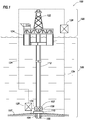
- FIG. 1 depicts an offshore wellsite 100 having a blowout preventer (BOP) 108 configured to seal a wellbore 105 extending into a seabed 107.
- the BOP 108 has a seal assembly 102 positioned therein.
- the BOP 108 is part of a subsea system 106 positioned on the seabed 107.
- the subsea system 106 may also comprise a pipe (or tubular) 104 extending through the wellbore 105, a wellhead 110 about the wellbore 105, a conduit 112 extending from the wellbore 105, and other subsea devices, such as a stripper and a conveyance delivery system (not shown). While the wellsite 100 is depicted as a subsea operation, it will be appreciated that the wellsite 100 may be land or water based.
- a surface system 120 may be used to facilitate operations at the offshore wellsite 100.
- the surface system 120 may comprise a rig 122, a platform 124 (or vessel) and a surface controller 126. Further, there may be one or more subsea controllers 128. While the surface controller 126 is shown as part of the surface system 120 at a surface location and the subsea controller 128 is shown part of the subsea system 106 in a subsea location, it will be appreciated that one or more controllers may be located at various locations to control the surface and/or subsea systems.
- the surface controller 126 and/or the subsea controller 128 may be placed in communication.
- the surface controller 126, the subsea controller 128, and/or any devices at the wellsite 100 may communicate via one or more communication links 134.
- the communication links 134 may be any suitable communication means, such as hydraulic lines, pneumatic lines, wiring, fiber optics, telemetry, acoustics, wireless communication, any combination thereof, and the like.
- the BOP 108 and/or other devices at the wellsite 100 may be automatically, manually and/or selectively operated via the controllers 126 and/or 128.
- FIG 2 shows a detailed, schematic view of a BOP 108 that may be used as the BOP 108 of Figure 1 .
- the BOP 108 may be a conventional BOP having a body 236 with a central passageway 238 therethrough for receiving a pipe (e.g., 104 of Figure 1 ).
- the BOP 108 also includes a pair of conventional ram assemblies 240, 242 on opposite sides thereof. Examples of BOPs, ram assemblies and/or ram blocks usable with the BOP 108 are described in U.S. Patent No. 5735502 .
- the ram assembly 240 has been pivotally retracted to reveal ram block 247.
- the seal assembly 102 is positionable within each of the ram blocks 247 for providing a seal with a pipe positioned in the central passageway 238.
- Each ram assembly 240, 242 is in communication with a respective one of the radially opposing chambers 244 in the BOP body that extend radially outward from the central passageway 238.
- Each ram assembly 240, 242 may include a ram body 246, the ram block 247 and a ram door 248.
- Ram door 248 may be secured to the BOP body 236 by conventional bolts (not shown) which pass through respective apertures 250 in the ram door 248 and thread to corresponding ports 251 in the BOP body 236.
- the ram assemblies 240, 242 may be pivotally mounted on the BOP body 236 by pivot arms 252, thereby facilitating repair and maintenance of the ram blocks 247.
- Bolts in the passageway 250 may thus be unthreaded from the BOP body 236, and the ram assembly 240 swung open, as shown in Figure 2 , to expose the ram block 247.
- the ram blocks 247 have an arcuate shaped body with an arcuate shaped inlet 259 configured to receive a portion of the pipe 104 for sealing engagement therewith. Once in position, the ram block 247 may be selectively activated to move within the seal assembly 102 to a sealed position about the pipe 104 positioned therein.
- FIGs 3A-3B show a portion of conventional ram blocks assemblies 12, 14 in various positions about the pipe 104.
- the ram block assemblies 12, 14 may be used as part of the ram blocks 247 of Figure 2 .
- the ram blocks 247 are provided with a seal assembly 102 thereon for supporting a rubber gland (or seal) 249.
- the seal assembly 102 may be configured to seal on multiple pipe diameters.
- the rubber gland 249 is advanced toward the drill pipe 104 and forced under hydraulic pressure to conform to the drill pipe 104.
- the rubber gland 249 may be molded with inserts (or metal reinforcements) 20 that aid in retaining the gland 249 and/or prevent rubber extrusion.
- the inserts 20 are positionable in an elliptical, iris configuration, sometimes referred to as an insert array.
- the movement of the inserts 20 is similar to the iris of an eye that alters the inner diameter of the pupil (or hole) receiving the pipe 104.
- the inserts 20 are slidingly moveable between a retracted (or unsealed) and a sealed position, and interlocked for cooperative movement therebetween.
- the inserts 20 are designed to support the rubber gland 249 to enhance a seal formed by the rubber gland 249 about the pipe 104 during operation.
- inserts 20 are detailed in Figures 4A-4C . These inserts 20 are described in further detail in US Patent No. 6,857,634 .
- the inserts 20 have an upper body 24 and a lower body 26. Each of the upper and lower bodies 24, 26 are provided with a ledge 30 and a corresponding recess 36 and an anti-extrusion ledge 46 thereon.
- the inserts 20 may optionally be provided with geometries that provide support to the seal assembly 102 and/or reduce extrusion of the rubber gland 249 about the pipe 104 during operation of the ram blocks 247.
- Figure 5A shows a portion of the array of inserts 20 of Figure 3B .
- conventional inserts 20 define an inner diameter 560 for receiving pipe 104 ( Figure 1 ).
- the inserts 20 have tips 564 at an end adjacent the inner diameter 560, and may define gaps 562 between the inserts 20 along the inner diameter 560. These large gaps provide space between the inserts and the drill pipe that define an extrusion path or gap for the rubber gland 249. In some cases, extrusion gaps of up to 0.125 inches (0.32 cm) may be present.
- alternate inserts 20a are provided with extended tips 564a that extend beyond a secondary tip 565a on a seal end of the insert 20a.
- the extended tips 564a may be used to provide a reduced gap 562a therebetween along inner diameter 560a.
- the geometry of the inserts 20a may be used to minimize the extrusion gap 562a by providing geometry that incrementally matches various pipe sizes. The shape, size and quantity of the geometries may vary based on a desired range of coverage and/or operating conditions.
- the inserts may be provided with various features, such as scallops (or facets) as will be described further herein, to reduce this gap to, for example, about 0.015-0.030 inches (0.38 - 0.76 mm) or less.
- the inserts may also have overlapping features, such as tips, ledges or shoulders as will be described further herein, to allow greater surface area to distribute the features.
- Such overlapping features may be used on portions of the insert for supporting an adjacent insert from internal rubber pressures, preventing extrusion between inserts, and/or adding stiffness to the seal assembly.
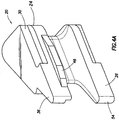
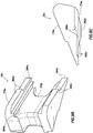
- Figures 6A-6D show various views of an insert 20a usable in the seal assembly 102 of Figures 1-3B .
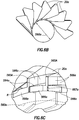
- Figure 6A shows an elliptical array of the inserts 20a forming a portion of an alternate seal assembly 102a and defining a variable inner diameter 560a.
- Figure 6B shows a portion of the array of inserts 20a of Figure 6A taken along line 6B-6B.
- Figure 6C is a detailed view of a portion 6C of the assembly 102a of Figure 6A .
- Figure 6D is a detailed view of two of the inserts 20a interlocked together for slidable movement therebetween.
- the inserts 20a may be provided with extended (or pointed) tips 564a that terminate at a point to fill the gap 562a (see, e.g., Figure 5B ).
- the extended tip 564a may, for example, have a radius R of about 0.03 - 0.05 inches (0.76 - 1.27 mm) near an end thereof.
- a tip receptacle 667a may be provided in the insert 20a for receiving the extended tip 564a of an adjacent insert 20a, and for providing overlap between the inserts 20a, as will be described further herein.
- the elliptical array of inserts defines an inner contact surface for engaging the pipe.
- the inserts 20a may also be provided with scallops (or contact surfaces) 566a for engaging the pipe 104 and further filling the gaps 562a about inner diameter 560a.
- One or more scallops 566a may be provided along the extended tip to define the contact surface for receiving the pipe 104.
- Multiple scallops may be provided to a curved contact surface that may conform to the shape of a variety of pipe diameters.
- the inserts may contract and expand about the pipe to conform to the size and shape of the pipe, and the shape of the scallops can conform to the various pipes.
- FIGS 7A-7D show the inserts 20a in greater detail.
- the inserts 20a cooperate with each other to radially expand and contract in an iris pattern (see, e.g., Figure 3B , 6B ).
- Each insert 20a has an upper body 768a and a lower body 770a with a rib 772a therebetween integrally made of metal.
- the upper body 768a has the same shape as the lower body 770a and is a mirror image thereof.
- the rib 772a is substantially smaller than the upper body 768a and lower body 770a to allow the rubber gland 249 to flow between the metal inserts 20a as the ram blocks 247 are pressed together as shown in Figure 3B .
- the upper body 768a and the lower body 770a each have a leading face 774a a shown in Figure 7A and a trailing face 776a as shown in Figure 7B .
- the leading face 774a and the trailing face 776a meet at the extended tip 564a on one end beyond secondary tip 565a, and are joined by a heel (or radially outwardly opposing face) 778a at an opposite end thereof.
- the upper body 768a and the lower body 770a each also have an inverted ledge 782a extending from the leading face 774a, and an inverted recess 784a indented into the trailing face 776a as shown in Figure 7C .
- the inverted recess 784a is configured to receive the inverted ledge 782a of an adjacent insert as depicted in Figure 6D for slidable support therebetween.
- the inverted recess 784a and the inverted ledge 782a may be mated to cooperatively interact similar to the ledge 30 and recess 36 of Figure 4A .
- the ledges 782a and recesses 784a may be inverted from the configuration of ledge 30 and recess 36 positioned on an outer surface of the insert 20 of Figure 4A .
- the ledges 782a and recesses 784a are positioned on an inner surface of the upper and lower bodies 768a, 770a to further support the inserts 20a as pressure is applied thereto during a sealing operation.
- the leading face 774a has a plurality of scallops (or contact surfaces or facets) 566a on a portion thereof as shown in Figure 7A .
- One or more scallops 566a may be provided. As shown, four scallops 566a extend into the leading face 774a.
- the scallops 566a may be concave indentations configured to receivingly engage the pipe 104.
- the scallops 566a of adjacent inserts 20a are preferably shaped to conform to the shape of the inner diameter 560a ( Figure 4B ).
- the scallops 566a may also be shaped such that, as the inner diameter 560a defined by the inserts adjusts to a given pipe size, the scallops 566a conform to the pipe shape.
- scallops 566a may be added to provide conformity to more pipe sizes.
- the scallops 566a may define an edge 787a therebetween.
- the edges 787a may optionally be flattened or curved to provide a smoother transition between the scallops 566a.
- Figure 7D shows a portion of the insert 20a depicting the extended tip 564a in greater detail.
- Figures 7E and 7F show views of a portion of an array of the inserts 20a.
- the insert 20a has a tip receptacle 667a extending into the upper body 768a for receiving the extended tip 564a of an adjacent insert 20a.
- This overlapped configuration may be used to more tightly fit the inserts 20a together, and further conform the extended tip 564a to the shape of the pipe. Additionally, this overlapping configuration may be used to further prevent extrusion between inserts.
- Figures 8A-8B show an alternate insert 20b that is similar to the insert 20a, except that the upper body 768b and lower body 770b each have a recess 888b extending into leading face 774b with corresponding ledges 890b extending into trailing face 776b.
- the upper body 768b and the lower body 770b have a rib 772b therebetween.
- the recess 888b and ledges 890b are upright (not inverted as shown in the insert 20a of Figures 7A-7F ), and are positioned on an outer surface of the insert 20b.
- the recess 888b and ledge 890b may cooperatively interact similarly to the ledge 30 and recess 36 of Figure 4A .
- One or more recesses 888b and corresponding ledges 890b may be provided about various portions of the upper and/or lower body 786b, 770b of each insert 20b.
- a shoulder (or radially inwardly directed anti-extrusion ledge) 892b extends from the leading face 774b and a corresponding ridge 894b extends into a trailing face 776b in the upper body 786b on each insert 20a.
- the shoulder 892b and ridge 894b may operate similar to the radially inwardly directed anti-extrusion ledge 46 of the insert 20 of Figure 4A .
- the shoulder 892b and ridge 894b define a first tier for interaction between the inserts 20b.
- the ledge 890b extends from the trailing face 776b to define a second tier for interaction with recess 888b. This two tier configuration may be used to support the cooperative movement and support of the inserts 20b, and prevent extrusion therebetween.
- One or more shoulders 892b and corresponding ridges 894b may also be provided about various portions of the insert 20b to provide support and/or prevent extrusion between adjacent inserts.
- Scallops 566b adjacent extended tip 564b similar to the scallops 566a of Figures 7A-7C , may also be provided to reduce the gaps between the inserts 20b and further prevent extrusion therebetween.
- Extended tip 564b is provided with a secondary tip 565b therebelow.
- Figures 9A-9B show an alternate insert 20c that is similar to the insert 20b, except that the upper body 768c and lower body 770c each have multiple recesses 888c extending into leading face 774c with corresponding upright ledges 890c extending into trailing face 776c.
- the upper body 768c and the lower body 770c have a rib 772c therebetween.
- the multiple recesses 888c and multiple ledges 890c may cooperatively interact similarly to the ledges 890b and recesses 888b of Figures 8A-8B .
- multiple recesses 888c and corresponding ledges 890c are provided at various depths to provide for additional contact between adjacent inserts.
- Additional ledges 890c and recesses 888c may be used to increase the amount of overlap between inserts and/or to reduce extrusion therebetween.
- One or more recesses 888c and corresponding ledges 890c for receiving that shoulder may also be provided about various portions of the upper and/or lower body of each insert 20c.
- the insert 20c may also be provided with a shoulder (or radially inwardly directed antiextrusion ledge) 892c extending from the leading face 774c and a corresponding ridge 894c extending into the trailing face 776c in the upper body 786c on each insert 20c.
- the shoulder 892c and ridge 894c may operate similar to the shoulder 892b and ridge 894b of Figures 8A and 8B .
- the recesses 888c and shoulders 890c define a first and second tier for interaction between the inserts 20c.
- the shoulder 892c extends from the leading face 774c to define a third tier for interaction between the inserts 20c.
- This three tier configuration may be used to support the cooperative movement and support of the inserts 20c, and prevent extrusion therebetween.
- One or more shoulders 892c and corresponding ridges 894c may also be provided about various portions of the insert 20c to provide support and/or prevent extrusion between adjacent inserts.
- Scallops 566c positioned about extended tip 564c similar to the scallops 566a of Figures 7A-7C , may also be provided to reduce the gaps between the inserts 20c and further prevent extrusion therebetween.
- Two extended tips 564c are provided with a secondary tip 565c therebelow.
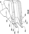
- FIGs 10A-10C show views of a portion of an array of the inserts 20c.
- Each insert 20c has a tip receptacle 667c extending into the upper body 768c and lower body 770c for receiving the extended tip 564c of an adjacent insert 20c as shown in Figures 10A and 10B .
- This overlapped configuration may be used to more tightly fit the inserts 20c together, and further conform the extended tips 564c to the shape of the pipe.
- Figure 10C also shows the ledges 890c and shoulder 892c of a first insert 20c being received by the recesses 888c and ridge 894c, respectively of an adjacent insert 20c for further overlap therebetween. These overlapping configurations may also be used to further prevent extrusion between inserts.
- the ram blocks 247 may actuated between the retracted position of Figure 4A and to the sealed position of Figure 4B .
- the inserts 20a-c of the seal assembly 102a-c may slidingly move to cooperatively conform to the shape of the pipe 104 for sealing engagement therewith.
- the inserts 20a-c may be provided with various combinations of features, such as recesses, shoulders, ridges, scallops, receptacles, and extended tips to enhance operation of the seal assembly.
- the techniques disclosed herein can be implemented for automated/autonomous applications via software configured with algorithms to perform the desired functions. These aspects can be implemented by programming one or more suitable general-purpose computers having appropriate hardware. The programming may be accomplished through the use of one or more program storage devices readable by the processor(s) and encoding one or more programs of instructions executable by the computer for performing the operations described herein.
- the program storage device may take the form of, e.g., one or more floppy disks; a CD ROM or other optical disk; a read-only memory chip (ROM); and other forms of the kind well known in the art or subsequently developed.
- the program of instructions may be "object code,” i.e., in binary form that is executable more-or-less directly by the computer; in "source code” that requires compilation or interpretation before execution; or in some intermediate form such as partially compiled code.
- object code i.e., in binary form that is executable more-or-less directly by the computer
- source code that requires compilation or interpretation before execution
- some intermediate form such as partially compiled code.
- the precise forms of the program storage device and of the encoding of instructions are immaterial here. Aspects of the disclosure may also be configured to perform the described functions (via appropriate hardware/software) solely on site and/or remotely controlled via an extended communication (e.g., wireless, internet, satellite, etc.) network.
- extended communication e.g., wireless, internet, satellite, etc.
Description
- The present disclosure relates generally to oilfield operations. More specifically, the present disclosure relates to techniques for sealing a wellbore.
- Oilfield operations are typically performed to locate and gather valuable downhole fluids. Oil rigs are positioned at wellsites and downhole tools, such as drilling tools, are deployed into the ground to reach subsurface reservoirs. Once the downhole tools form a wellbore to reach a desired reservoir, casings may be cemented into place within the wellbore, and the wellbore completed to initiate production of fluids from the reservoir. Tubing or pipes are typically positioned in the wellbore to enable the passage of subsurface fluids to the surface.
- Leakage of subsurface fluids may pose a significant environmental threat if released from the wellbore. Equipment, such as blow out preventers (BOPs), are often positioned about the wellbore to form a seal about pipes and to prevent leakage of fluid as it is brought to the surface. BOPs may employ rams and/or ram blocks that seal the wellbore. Some examples of ram BOPs and/or ram blocks are provided in U.S. Patent/Application Nos.
4647002 ,6173770 ,5025708 ,7051989 ,5575452 ,6374925 ,20080265188 ,5735502 ,5897094 ,7234530 and2009/0056132 . The BOPs may be provided with various devices to seal various portions of the BOP as described, for example, in US Patent Nos.4508311 ,5975484 and6955357 . Despite the development of sealing techniques, there remains a need to provide advanced techniques for sealing wellbores.US Patent No 6857634 is considered the closest prior art document to the subject-matter under consideration. - The present disclosure relates to techniques for sealing a pipe of a wellbore. Inserts may be positioned in a seal assembly of carried by a pair of opposing ram blocks of a blowout preventer. The inserts have upper and lower bodies with a rib therebetween. The upper and lower bodies are provided with extended tips on a seal end thereof and tip receptacles on a leading face thereof. The extended tips are receivable in the tip receptacles of an adjacent insert to restrict extrusion of therebetween. The upper and lower bodies may also be provided with recesses and ledges for interlocking engagement and slidable movement between the inserts. Scallops may be provided along the tips to conform to various pipe diameters.
- In another aspect, the disclosure relates to a seal assembly of a blowout preventer. The blowout preventer includes a pair of opposing ram blocks positionable about a pipe of a wellsite. The seal assembly includes a pair of seals carried by the pair of opposing ram blocks and a plurality of inserts. The inserts carried by the pair of seals and positionable about the pipe in an elliptical array. Each of the inserts having an upper body and a lower body with a rib therebetween. Each of the upper and lower bodies have an extended tip on a seal end thereof and a tip receptacle on a leading face thereof. The extended tips of the upper and lower bodies of each of the inserts are receivable in the tip receptacles of an adjacent one of the inserts whereby extrusion of the pair of seals between the inserts is restricted.
- In yet another aspect, the disclosure relates to a blowout preventer for sealing a pipe of a wellsite. The blowout preventer includes a housing, a pair of opposing ram blocks positionable about a pipe of a wellsite, and a seal assembly. The seal assembly includes a pair of seals carried by the pair of opposing ram blocks and positionable in sealing engagement about the pipe and a plurality of inserts. The inserts are carried by the pair of seals and positionable about the pipe in an elliptical array. Each of the inserts have an upper body and a lower body with a rib therebetween. Each of the upper and lower bodies have an extended tip on a seal end thereof and a tip receptacle on a leading face thereof. The extended tips of the upper and lower bodies of each of the inserts are receivable in the tip receptacles of an adjacent one of the inserts whereby extrusion of the pair of seals between the inserts is restricted.
- Finally, in yet another aspect, the disclosure relates to a method of sealing a pipe of a wellsite. The method involves providing a blowout preventer including a housing, a pair of opposing ram blocks positionable about the pipe, and a seal assembly. The seal assembly includes a pair of seals carried by the opposing ram blocks and a plurality of inserts. The carried by the seals. The inserts have an upper body and a lower body with a rib therebetween. Each of the upper and lower bodies has an extended tip on a seal end thereof and a tip receptacle on a leading face thereof. The method further involves positioning the inserts of the seal assembly about the pipe in an elliptical array by advancing the opposing ram blocks toward the pipe, and restricting extrusion of the pair of seals between the inserts by receiving the extended tips of the upper and lower bodies of each of the inserts in the tip receptacles of an adjacent one of the inserts.
- So that the above recited features and advantages of the present disclosure can be understood in detail, a more particular description of the technology herein, briefly summarized above, may be had by reference to the embodiments thereof that are illustrated in the appended drawings. It is to be noted, however, that the appended drawings illustrate only typical embodiments of this technology and are, therefore, not to be considered limiting of its scope, for the disclosure may admit to other equally effective embodiments. The figures are not necessarily to scale, and certain features and certain views of the figures may be shown exaggerated in scale or in schematic in the interest of clarity and conciseness.
-
Figure 1 is a schematic view of an offshore wellsite having a BOP with a seal assembly therein according to the disclosure. -
Figure 2 is a schematic view of the BOP ofFigure 1 having ram blocks with the seal assembly thereon. -
Figures 3A and 3B are schematic views of ram blocks with a seal assembly thereon in a retracted and sealed position, respectively. -
Figures 4A-4C are various schematic views of an insert of a seal assembly. -
Figures 5A and 5B are schematic views of a portion of a seal assembly having a gap and a reduced gap, respectively. -
Figures 6A-6D are various schematic views of various portions of a seal assembly having a plurality of inserts in accordance with the disclosure. -
Figures 7A-7D are various schematic views of one of the inserts ofFigure 6A . -
Figures 7E-7F are various schematic views of a portion of a seal assembly having a plurality of the inserts ofFigure 7A . -
Figures 8A-8C are schematic views of an alternate insert. -
Figures 9A-9C are schematic views of another alternate insert. -
Figures 10A-10C are various schematic views of a portion of a seal assembly having a plurality of the inserts ofFigure 9A . - The description that follows includes exemplary apparatuses, methods, techniques, and instruction sequences that embody techniques of the present subject matter. However, it is understood that the described embodiments may be practiced without these specific details.
- The disclosure relates to techniques for sealing a wellbore. The techniques involve inserts used, for example, in a ram block of a blowout preventer. The inserts may be positioned about a tubular (or pipe) for forming a seal therewith. It may be desirable to provide techniques that more effectively seal, even under high pressure conditions. It may be further desirable to provide techniques that more effectively seal about a variety of pipe diameters. Preferably, such techniques involve one or more of the following, among others: ease of operation, simple design, adaptability to a variety of applications, reduced failures, performance under harsh conditions, conformance to equipment shapes and/or sizes, increased capacity, etc. The present disclosure is directed to fulfilling these needs in the art.
-
Figure 1 depicts anoffshore wellsite 100 having a blowout preventer (BOP) 108 configured to seal awellbore 105 extending into aseabed 107. TheBOP 108 has aseal assembly 102 positioned therein. As shown, theBOP 108 is part of asubsea system 106 positioned on theseabed 107. Thesubsea system 106 may also comprise a pipe (or tubular) 104 extending through thewellbore 105, awellhead 110 about thewellbore 105, aconduit 112 extending from thewellbore 105, and other subsea devices, such as a stripper and a conveyance delivery system (not shown). While thewellsite 100 is depicted as a subsea operation, it will be appreciated that thewellsite 100 may be land or water based. - A
surface system 120 may be used to facilitate operations at theoffshore wellsite 100. Thesurface system 120 may comprise arig 122, a platform 124 (or vessel) and asurface controller 126. Further, there may be one or moresubsea controllers 128. While thesurface controller 126 is shown as part of thesurface system 120 at a surface location and thesubsea controller 128 is shown part of thesubsea system 106 in a subsea location, it will be appreciated that one or more controllers may be located at various locations to control the surface and/or subsea systems. - To operate the
BOP 108 and/or other devices associated with thewellsite 100, thesurface controller 126 and/or thesubsea controller 128 may be placed in communication. Thesurface controller 126, thesubsea controller 128, and/or any devices at thewellsite 100 may communicate via one or more communication links 134. The communication links 134 may be any suitable communication means, such as hydraulic lines, pneumatic lines, wiring, fiber optics, telemetry, acoustics, wireless communication, any combination thereof, and the like. TheBOP 108 and/or other devices at thewellsite 100 may be automatically, manually and/or selectively operated via thecontrollers 126 and/or 128. -
Figure 2 shows a detailed, schematic view of aBOP 108 that may be used as theBOP 108 ofFigure 1 . TheBOP 108 may be a conventional BOP having abody 236 with acentral passageway 238 therethrough for receiving a pipe (e.g., 104 ofFigure 1 ). TheBOP 108 also includes a pair ofconventional ram assemblies BOP 108 are described inU.S. Patent No. 5735502 . Theram assembly 240 has been pivotally retracted to revealram block 247. Theseal assembly 102 is positionable within each of the ram blocks 247 for providing a seal with a pipe positioned in thecentral passageway 238. - Each
ram assembly chambers 244 in the BOP body that extend radially outward from thecentral passageway 238. Eachram assembly ram body 246, theram block 247 and aram door 248.Ram door 248 may be secured to theBOP body 236 by conventional bolts (not shown) which pass throughrespective apertures 250 in theram door 248 and thread to correspondingports 251 in theBOP body 236. - The
ram assemblies BOP body 236 bypivot arms 252, thereby facilitating repair and maintenance of the ram blocks 247. Bolts in thepassageway 250 may thus be unthreaded from theBOP body 236, and theram assembly 240 swung open, as shown inFigure 2 , to expose theram block 247. - The ram blocks 247 have an arcuate shaped body with an arcuate shaped
inlet 259 configured to receive a portion of thepipe 104 for sealing engagement therewith. Once in position, theram block 247 may be selectively activated to move within theseal assembly 102 to a sealed position about thepipe 104 positioned therein. -
Figures 3A-3B show a portion of conventionalram blocks assemblies pipe 104. Theram block assemblies Figure 2 . The ram blocks 247 are provided with aseal assembly 102 thereon for supporting a rubber gland (or seal) 249. Theseal assembly 102 may be configured to seal on multiple pipe diameters. During activation of the ram blocks 247, therubber gland 249 is advanced toward thedrill pipe 104 and forced under hydraulic pressure to conform to thedrill pipe 104. To protect the rubber gland 249 (and potentially extend its life), therubber gland 249 may be molded with inserts (or metal reinforcements) 20 that aid in retaining thegland 249 and/or prevent rubber extrusion. - As shown in
Figure 3B , theinserts 20 are positionable in an elliptical, iris configuration, sometimes referred to as an insert array. The movement of theinserts 20 is similar to the iris of an eye that alters the inner diameter of the pupil (or hole) receiving thepipe 104. Theinserts 20 are slidingly moveable between a retracted (or unsealed) and a sealed position, and interlocked for cooperative movement therebetween. Theinserts 20 are designed to support therubber gland 249 to enhance a seal formed by therubber gland 249 about thepipe 104 during operation. - Conventional inserts 20 are detailed in
Figures 4A-4C . Theseinserts 20 are described in further detail inUS Patent No. 6,857,634 . Theinserts 20 have anupper body 24 and alower body 26. Each of the upper andlower bodies ledge 30 and acorresponding recess 36 and ananti-extrusion ledge 46 thereon. - To enhance the operation of the
seal assembly 102, theinserts 20 may optionally be provided with geometries that provide support to theseal assembly 102 and/or reduce extrusion of therubber gland 249 about thepipe 104 during operation of the ram blocks 247.Figure 5A shows a portion of the array ofinserts 20 ofFigure 3B . As shown inFigure 5A ,conventional inserts 20 define aninner diameter 560 for receiving pipe 104 (Figure 1 ). Theinserts 20 havetips 564 at an end adjacent theinner diameter 560, and may definegaps 562 between theinserts 20 along theinner diameter 560. These large gaps provide space between the inserts and the drill pipe that define an extrusion path or gap for therubber gland 249. In some cases, extrusion gaps of up to 0.125 inches (0.32 cm) may be present. - To reduce or restrict the extrusion between the inserts, it may be desirable to reduce the
gaps 562. These reduced gaps may reduce the open area (or space) between thepipe 104 and theinserts 20 to restrict extrusion therethrough. As shown inFigure 5B ,alternate inserts 20a are provided withextended tips 564a that extend beyond asecondary tip 565a on a seal end of theinsert 20a. Theextended tips 564a may be used to provide a reduced gap 562a therebetween alonginner diameter 560a. The geometry of theinserts 20a may be used to minimize the extrusion gap 562a by providing geometry that incrementally matches various pipe sizes. The shape, size and quantity of the geometries may vary based on a desired range of coverage and/or operating conditions. - The inserts may be provided with various features, such as scallops (or facets) as will be described further herein, to reduce this gap to, for example, about 0.015-0.030 inches (0.38 - 0.76 mm) or less. In addition the inserts may also have overlapping features, such as tips, ledges or shoulders as will be described further herein, to allow greater surface area to distribute the features. Such overlapping features may be used on portions of the insert for supporting an adjacent insert from internal rubber pressures, preventing extrusion between inserts, and/or adding stiffness to the seal assembly.
-
Figures 6A-6D show various views of aninsert 20a usable in theseal assembly 102 ofFigures 1-3B .Figure 6A shows an elliptical array of theinserts 20a forming a portion of analternate seal assembly 102a and defining a variableinner diameter 560a.Figure 6B shows a portion of the array ofinserts 20a ofFigure 6A taken alongline 6B-6B.Figure 6C is a detailed view of aportion 6C of theassembly 102a ofFigure 6A .Figure 6D is a detailed view of two of theinserts 20a interlocked together for slidable movement therebetween. - As shown in
Figures 6C-6D , theinserts 20a may be provided with extended (or pointed)tips 564a that terminate at a point to fill the gap 562a (see, e.g.,Figure 5B ). Theextended tip 564a may, for example, have a radius R of about 0.03 - 0.05 inches (0.76 - 1.27 mm) near an end thereof. Atip receptacle 667a may be provided in theinsert 20a for receiving theextended tip 564a of anadjacent insert 20a, and for providing overlap between theinserts 20a, as will be described further herein. - The elliptical array of inserts defines an inner contact surface for engaging the pipe. The
inserts 20a may also be provided with scallops (or contact surfaces) 566a for engaging thepipe 104 and further filling the gaps 562a aboutinner diameter 560a. One ormore scallops 566a may be provided along the extended tip to define the contact surface for receiving thepipe 104. Multiple scallops may be provided to a curved contact surface that may conform to the shape of a variety of pipe diameters. The inserts may contract and expand about the pipe to conform to the size and shape of the pipe, and the shape of the scallops can conform to the various pipes. -
Figures 7A-7D show theinserts 20a in greater detail. Theinserts 20a cooperate with each other to radially expand and contract in an iris pattern (see, e.g.,Figure 3B ,6B ). Eachinsert 20a has anupper body 768a and alower body 770a with arib 772a therebetween integrally made of metal. Theupper body 768a has the same shape as thelower body 770a and is a mirror image thereof. Therib 772a is substantially smaller than theupper body 768a andlower body 770a to allow therubber gland 249 to flow between the metal inserts 20a as the ram blocks 247 are pressed together as shown inFigure 3B . - The
upper body 768a and thelower body 770a each have aleading face 774a a shown inFigure 7A and a trailingface 776a as shown inFigure 7B . The leadingface 774a and the trailingface 776a meet at theextended tip 564a on one end beyondsecondary tip 565a, and are joined by a heel (or radially outwardly opposing face) 778a at an opposite end thereof. Theupper body 768a and thelower body 770a each also have an invertedledge 782a extending from the leadingface 774a, and aninverted recess 784a indented into the trailingface 776a as shown inFigure 7C . Theinverted recess 784a is configured to receive theinverted ledge 782a of an adjacent insert as depicted inFigure 6D for slidable support therebetween. Theinverted recess 784a and theinverted ledge 782a may be mated to cooperatively interact similar to theledge 30 andrecess 36 ofFigure 4A . Theledges 782a andrecesses 784a may be inverted from the configuration ofledge 30 andrecess 36 positioned on an outer surface of theinsert 20 ofFigure 4A . In the inverted configuration, theledges 782a andrecesses 784a are positioned on an inner surface of the upper andlower bodies inserts 20a as pressure is applied thereto during a sealing operation. - The leading
face 774a has a plurality of scallops (or contact surfaces or facets) 566a on a portion thereof as shown inFigure 7A . One ormore scallops 566a may be provided. As shown, fourscallops 566a extend into the leadingface 774a. Thescallops 566a may be concave indentations configured to receivingly engage thepipe 104. To further reduce the gap 562a (Figure 5B ), thescallops 566a ofadjacent inserts 20a are preferably shaped to conform to the shape of theinner diameter 560a (Figure 4B ). Thescallops 566a may also be shaped such that, as theinner diameter 560a defined by the inserts adjusts to a given pipe size, thescallops 566a conform to the pipe shape.Additional scallops 566a may be added to provide conformity to more pipe sizes. In some cases, thescallops 566a may define anedge 787a therebetween. Theedges 787a may optionally be flattened or curved to provide a smoother transition between thescallops 566a. -
Figure 7D shows a portion of theinsert 20a depicting theextended tip 564a in greater detail.Figures 7E and 7F show views of a portion of an array of theinserts 20a. Theinsert 20a has atip receptacle 667a extending into theupper body 768a for receiving theextended tip 564a of anadjacent insert 20a. This overlapped configuration may be used to more tightly fit theinserts 20a together, and further conform theextended tip 564a to the shape of the pipe. Additionally, this overlapping configuration may be used to further prevent extrusion between inserts. -
Figures 8A-8B show analternate insert 20b that is similar to theinsert 20a, except that theupper body 768b andlower body 770b each have arecess 888b extending into leadingface 774b withcorresponding ledges 890b extending into trailingface 776b. Theupper body 768b and thelower body 770b have arib 772b therebetween. In this configuration, therecess 888b andledges 890b are upright (not inverted as shown in theinsert 20a ofFigures 7A-7F ), and are positioned on an outer surface of theinsert 20b. Therecess 888b andledge 890b may cooperatively interact similarly to theledge 30 andrecess 36 ofFigure 4A . One ormore recesses 888b andcorresponding ledges 890b may be provided about various portions of the upper and/orlower body 786b, 770b of eachinsert 20b. - As shown in
Figures 8A and8B , a shoulder (or radially inwardly directed anti-extrusion ledge) 892b extends from the leadingface 774b and acorresponding ridge 894b extends into a trailingface 776b in the upper body 786b on eachinsert 20a. Theshoulder 892b andridge 894b may operate similar to the radially inwardly directedanti-extrusion ledge 46 of theinsert 20 ofFigure 4A . - The
shoulder 892b andridge 894b define a first tier for interaction between theinserts 20b. Theledge 890b extends from the trailingface 776b to define a second tier for interaction withrecess 888b. This two tier configuration may be used to support the cooperative movement and support of theinserts 20b, and prevent extrusion therebetween. One ormore shoulders 892b and correspondingridges 894b may also be provided about various portions of theinsert 20b to provide support and/or prevent extrusion between adjacent inserts.Scallops 566b adjacentextended tip 564b, similar to thescallops 566a ofFigures 7A-7C , may also be provided to reduce the gaps between theinserts 20b and further prevent extrusion therebetween.Extended tip 564b is provided with asecondary tip 565b therebelow. -
Figures 9A-9B show analternate insert 20c that is similar to theinsert 20b, except that theupper body 768c andlower body 770c each havemultiple recesses 888c extending into leadingface 774c with correspondingupright ledges 890c extending into trailingface 776c. Theupper body 768c and thelower body 770c have arib 772c therebetween. Themultiple recesses 888c andmultiple ledges 890c may cooperatively interact similarly to theledges 890b and recesses 888b ofFigures 8A-8B . In this case,multiple recesses 888c andcorresponding ledges 890c are provided at various depths to provide for additional contact between adjacent inserts.Additional ledges 890c andrecesses 888c may be used to increase the amount of overlap between inserts and/or to reduce extrusion therebetween. One ormore recesses 888c andcorresponding ledges 890c for receiving that shoulder may also be provided about various portions of the upper and/or lower body of eachinsert 20c. - As shown in
Figures 9A and9B , theinsert 20c may also be provided with a shoulder (or radially inwardly directed antiextrusion ledge) 892c extending from the leadingface 774c and acorresponding ridge 894c extending into the trailingface 776c in the upper body 786c on eachinsert 20c. Theshoulder 892c andridge 894c may operate similar to theshoulder 892b andridge 894b ofFigures 8A and8B . - The
recesses 888c andshoulders 890c define a first and second tier for interaction between theinserts 20c. Theshoulder 892c extends from the leadingface 774c to define a third tier for interaction between theinserts 20c. This three tier configuration may be used to support the cooperative movement and support of theinserts 20c, and prevent extrusion therebetween. One ormore shoulders 892c and correspondingridges 894c may also be provided about various portions of theinsert 20c to provide support and/or prevent extrusion between adjacent inserts.Scallops 566c positioned about extendedtip 564c, similar to thescallops 566a ofFigures 7A-7C , may also be provided to reduce the gaps between theinserts 20c and further prevent extrusion therebetween. Twoextended tips 564c are provided with asecondary tip 565c therebelow. -
Figures 10A-10C show views of a portion of an array of theinserts 20c. Eachinsert 20c has atip receptacle 667c extending into theupper body 768c andlower body 770c for receiving theextended tip 564c of anadjacent insert 20c as shown inFigures 10A and 10B . This overlapped configuration may be used to more tightly fit theinserts 20c together, and further conform theextended tips 564c to the shape of the pipe.Figure 10C also shows theledges 890c andshoulder 892c of afirst insert 20c being received by therecesses 888c andridge 894c, respectively of anadjacent insert 20c for further overlap therebetween. These overlapping configurations may also be used to further prevent extrusion between inserts. - In an example operation, the ram blocks 247 may actuated between the retracted position of
Figure 4A and to the sealed position ofFigure 4B . Theinserts 20a-c of theseal assembly 102a-c may slidingly move to cooperatively conform to the shape of thepipe 104 for sealing engagement therewith. Theinserts 20a-c may be provided with various combinations of features, such as recesses, shoulders, ridges, scallops, receptacles, and extended tips to enhance operation of the seal assembly. - It will be appreciated by those skilled in the art that the techniques disclosed herein can be implemented for automated/autonomous applications via software configured with algorithms to perform the desired functions. These aspects can be implemented by programming one or more suitable general-purpose computers having appropriate hardware. The programming may be accomplished through the use of one or more program storage devices readable by the processor(s) and encoding one or more programs of instructions executable by the computer for performing the operations described herein. The program storage device may take the form of, e.g., one or more floppy disks; a CD ROM or other optical disk; a read-only memory chip (ROM); and other forms of the kind well known in the art or subsequently developed. The program of instructions may be "object code," i.e., in binary form that is executable more-or-less directly by the computer; in "source code" that requires compilation or interpretation before execution; or in some intermediate form such as partially compiled code. The precise forms of the program storage device and of the encoding of instructions are immaterial here. Aspects of the disclosure may also be configured to perform the described functions (via appropriate hardware/software) solely on site and/or remotely controlled via an extended communication (e.g., wireless, internet, satellite, etc.) network.
- While the present disclosure describes specific aspects of the disclosure, numerous modifications and variations will become apparent to those skilled in the art after studying the disclosure, including use of equivalent functional and/or structural substitutes for elements described herein. For example, aspects of the disclosure can also be implemented using various combinations of one or more recesses, shoulders, ridges, scallops, receptacles, extended tips and/or other features about various portions of the inserts. All such similar variations apparent to those skilled in the art are deemed to be within the scope of the disclosure as defined by the appended claims.
- Plural instances may be provided for components, operations or structures described herein as a single instance. In general, structures and functionality presented as separate components in the exemplary configurations may be implemented as a combined structure or component. Similarly, structures and functionality presented as a single component may be implemented as separate components. These and other variations, modifications, additions, and improvements may fall within the scope of the subject matter herein.
Claims (13)
- An insert for supporting a seal (249) of a seal assembly (102a) of a blowout preventer (108), the seal assembly positionable in sealing engagement with a pipe (104), the insert comprising:an upper body (768a) and a lower body (770a) with a rib (772a) therebetween, characterized in that each of the upper and lower bodies has an extended tip (564a) on a seal end thereof and a tip receptacle (667a,c) on a leading face (774b) thereof;wherein the extended tips of the upper and lower bodies of the insert are receivable in the tip receptacles of an adjacent insert whereby extrusion of the seal therebetween is restricted.
- The insert of claim 1, wherein the upper and lower bodies each have a plurality of scallops (566a,b) adjacent the extended tip.
- The insert of claim 1 or 2, wherein the upper and lower bodies each have at least one ledge (890b,c) and at least one recess (888b,c) for receiving the at least one ledge of the an adjacent insert.
- The insert of claim 3, wherein the at least one ledge comprises an inverted ledge (782a), an upright ledge (890b) or an anti-extrusion ledge (892c).
- The insert of claim 3 or 4, wherein the at least one recess comprises an inverted recess (784a), an upright recess (888b,c), or an anti-extrusion ridge (894c).
- The insert of any preceding claim, wherein the upper body further comprises a secondary tip (565a,b,c) a distance from the seal end.
- The insert of any preceding Claim, wherein a plurality of the inserts are positionable in the seal assembly of the blowout preventer, the blowout preventer comprising a housing, a pair of opposing ram blocks (247) positionable about the pipe of a wellsite (100), the seal assembly further comprising a pair of seals (249) carried by the pair of opposing ram blocks, the plurality of inserts carried by the pair of seals and positionable about the pipe in an elliptical array.
- The insert of Claim 7, wherein an inner diameter (560a) of the elliptical array is variable.
- The insert of Claim 7, wherein the plurality of inserts are interlocked together.
- The insert of any of Claims 7-9, wherein, when the plurality of inserts are positioned in sealing engagement with the pipe, an extrusion gap (562a) is defined between the plurality of inserts and the pipe to movably receive the pair of seals.
- The insert of any of Claims 7-10, wherein each of the plurality of inserts has at least one scallop (566a,b) about the extended tip such that, when positioned in the elliptical array about the pipe, the at least one scallop of the extended tips of the plurality of inserts defines an inner surface for receivingly engaging the pipe.
- A method of sealing a pipe (104) of a wellsite (100), the method comprising:providing a blowout preventer (108) comprising a housing, a pair of opposing ram blocks (247) positionable about the pipe with a seal assembly (102a), the seal assembly comprising:a pair of seals (249) carried by the pair of opposing ram blocks; anda plurality of inserts (20a) carried by the pair of seals, each of the plurality of inserts having an upper body (768a) and a lower body (770a) with a rib (772a) therebetween, each of the upper and lower bodies having an extended tip (564a) on a seal end thereof and a tip receptacle (667a) on a leading face (774b) thereof;positioning the plurality of inserts of the seal assembly about the pipe in an elliptical array by advancing the opposing ram blocks toward the pipe; andrestricting extrusion of the pair of seals between the plurality of inserts by receiving the extended tips of the upper and lower bodies of each of the plurality of inserts in the tip receptacles of an adjacent one of the plurality of inserts.
- The method of Claim 12, further comprising adjustably receiving pipes of various diameters.
Applications Claiming Priority (2)
| Application Number | Priority Date | Filing Date | Title |
|---|---|---|---|
| US201161450965P | 2011-03-09 | 2011-03-09 | |
| PCT/US2012/025767 WO2012121866A2 (en) | 2011-03-09 | 2012-02-19 | Method and apparatus for sealing a wellbore |
Publications (2)
| Publication Number | Publication Date |
|---|---|
| EP2683912A2 EP2683912A2 (en) | 2014-01-15 |
| EP2683912B1 true EP2683912B1 (en) | 2017-08-23 |
Family
ID=46000290
Family Applications (1)
| Application Number | Title | Priority Date | Filing Date |
|---|---|---|---|
| EP12716730.2A Active EP2683912B1 (en) | 2011-03-09 | 2012-02-19 | Method and apparatus for sealing a wellbore |
Country Status (9)
| Country | Link |
|---|---|
| US (1) | US8978751B2 (en) |
| EP (1) | EP2683912B1 (en) |
| KR (2) | KR20150092371A (en) |
| CN (1) | CN103502565B (en) |
| BR (1) | BR112013022928B1 (en) |
| CA (1) | CA2828956C (en) |
| NO (1) | NO2683912T3 (en) |
| SG (1) | SG193346A1 (en) |
| WO (1) | WO2012121866A2 (en) |
Families Citing this family (25)
| Publication number | Priority date | Publication date | Assignee | Title |
|---|---|---|---|---|
| US9045961B2 (en) | 2011-01-31 | 2015-06-02 | National Oilwell Varco, L.P. | Blowout preventer seal and method of using same |
| GB2493180A (en) * | 2011-07-27 | 2013-01-30 | Expro North Sea Ltd | Valve housing arrangement |
| US9175541B2 (en) | 2012-04-10 | 2015-11-03 | National Oilwell Varco, L.P. | Blowout preventer seal assembly and method of using same |
| CN104131798A (en) * | 2014-08-27 | 2014-11-05 | 上海神开石油化工装备股份有限公司 | Large-range variable-diameter flashboard for blowout preventer |
| US9580988B2 (en) * | 2014-12-09 | 2017-02-28 | Hydril USA Distribution LLC | Variable ram packer with strain reduction features |
| US9441443B2 (en) * | 2015-01-27 | 2016-09-13 | National Oilwell Varco, L.P. | Compound blowout preventer seal and method of using same |
| WO2016130979A1 (en) | 2015-02-13 | 2016-08-18 | National Oilwell Varco, L.P. | A detection system for a wellsite and method of using same |
| US10487614B2 (en) | 2015-05-29 | 2019-11-26 | Halliburton Energy Services, Inc. | Packing element back-up system incorporating iris mechanism |
| BR112018002780B1 (en) | 2015-08-14 | 2022-08-30 | National Oilwell Varco, L.P. | PREVENTIVE ERUPTION CONTROLLER, AND, SHUTTING ELEMENT |
| US9732577B2 (en) * | 2015-09-08 | 2017-08-15 | Axon Pressure Products, Inc. | Blowout preventer with hinged bonnet |
| US10161212B2 (en) * | 2015-11-24 | 2018-12-25 | Cameron International Corporation | Packer assembly with multiple different inserts for blowout preventer |
| NO343133B1 (en) * | 2016-03-30 | 2018-11-19 | Electrical Subsea & Drilling As | Annular blowout preventer |
| GB2567942B (en) | 2016-03-30 | 2019-12-11 | Electrical Subsea & Drilling As | Annular blowout preventer |
| NO343132B1 (en) * | 2016-03-30 | 2018-11-19 | Electrical Subsea and Drilling AS | Packer actuation system for a blowout preventer and blowout preventer |
| US10233715B2 (en) | 2016-07-25 | 2019-03-19 | Cameron International Corporation | Packer assembly with multi-material inserts for blowout preventer |
| GB2559109B (en) * | 2016-11-09 | 2021-05-05 | Peak Well Systems Pty Ltd | Expanding and collapsing apparatus and methods of use |
| US10590728B2 (en) | 2017-05-19 | 2020-03-17 | Cameron International Corporation | Annular blowout preventer packer assembly |
| GB201710367D0 (en) | 2017-06-28 | 2017-08-09 | Peak Well Systems Pty Ltd | Seal apparatus and methods of use |
| US10900347B2 (en) | 2018-03-01 | 2021-01-26 | Cameron International Corporation | BOP elastomer health monitoring |
| WO2019232052A1 (en) * | 2018-05-31 | 2019-12-05 | National Oilwell Varco, L.P. | Blowout preventer apparatus and method |
| US11459844B2 (en) * | 2019-08-27 | 2022-10-04 | Hydril USA Distribution LLC | Blowout preventer system and method |
| WO2022031509A1 (en) * | 2020-08-04 | 2022-02-10 | Texas Institute Of Science, Inc. | Variable bore ram packer and ram-type blowout preventer using same |
| US11603731B2 (en) | 2020-09-17 | 2023-03-14 | Baker Hughes Oilfield Operations Llc | Inserts for variable bore rams |
| CN114893143B (en) * | 2022-07-14 | 2022-09-09 | 威海海洋职业学院 | Ocean oil well wellhead assembly |
| WO2024030812A1 (en) * | 2022-08-05 | 2024-02-08 | Schlumberger Technology Corporation | Rotating control device with sealing insert |
Family Cites Families (277)
| Publication number | Priority date | Publication date | Assignee | Title |
|---|---|---|---|---|
| US2035925A (en) | 1933-05-24 | 1936-03-31 | Seamark Lewis Mervyn Cecil | Casing head equipment |
| US2193110A (en) | 1935-09-07 | 1940-03-12 | Kirby T Penick | Blowout preventer |
| US2178698A (en) | 1936-05-04 | 1939-11-07 | Arthur J Penick | Tubing head |
| US2194256A (en) | 1937-05-07 | 1940-03-19 | Cameron Iron Works Inc | Multiple seal blowout preventer |
| US2231613A (en) | 1940-04-03 | 1941-02-11 | Paul Stock | Blowout preventer and control head |
| US2304793A (en) | 1941-06-09 | 1942-12-15 | Calpat Corp | Method of and apparatus for cutting pipe |
| US2609836A (en) | 1946-08-16 | 1952-09-09 | Hydril Corp | Control head and blow-out preventer |
| US2592197A (en) | 1947-10-27 | 1952-04-08 | Jr Frank J Schweitzer | Side-plug hydraulic cellar gate |
| US2749078A (en) | 1951-06-26 | 1956-06-05 | Guiberson Corp | Well blowout preventer |
| US2752119A (en) | 1952-03-24 | 1956-06-26 | Cameron Iron Works Inc | Blowout preventer |
| US3028917A (en) | 1955-08-04 | 1962-04-10 | Mcevoy Co | Well completion apparatus |
| US3001803A (en) | 1956-05-07 | 1961-09-26 | Gray Tool Co | Wellhead |
| US3040611A (en) | 1956-11-15 | 1962-06-26 | Duralumin | Guillotine shears |
| US3242826A (en) | 1963-10-11 | 1966-03-29 | Shaffer Tool Works | Locking device for a fluid operated rod |
| US3272222A (en) | 1963-10-28 | 1966-09-13 | Cameron Iron Works Inc | Blowout preventer |
| US3282222A (en) | 1964-10-13 | 1966-11-01 | Itt | Rotating vane machines |
| US3434729A (en) | 1965-10-21 | 1969-03-25 | Shaffer Tool Works | Ram assembly |
| US3399728A (en) | 1966-12-01 | 1968-09-03 | Allan R. Taylor | Conduit closure apparatus |
| US3554480A (en) | 1968-01-16 | 1971-01-12 | Cameron Iron Works Inc | Blowout preventer |
| US3572628A (en) | 1968-10-04 | 1971-03-30 | Cameron Iron Works Inc | Blowout preventer |
| US3554278A (en) | 1969-07-31 | 1971-01-12 | Exxon Production Research Co | Pipe alignment apparatus |
| US3561526A (en) | 1969-09-03 | 1971-02-09 | Cameron Iron Works Inc | Pipe shearing ram assembly for blowout preventer |
| US3771601A (en) | 1970-07-16 | 1973-11-13 | H Garrett | Well bore blocking method |
| US3647174A (en) | 1970-09-25 | 1972-03-07 | Hydril Co | Blowout preventer |
| US3670761A (en) | 1970-10-13 | 1972-06-20 | Hydril Co | Blowout preventer with resistance means between the body and the piston |
| US3744749A (en) | 1971-05-18 | 1973-07-10 | Hydril Co | Blowout preventer with ram support and guide means |
| US3716068A (en) | 1971-06-11 | 1973-02-13 | F Addison | Surface controlled blowout arrester |
| US3741296A (en) | 1971-06-14 | 1973-06-26 | Hydril Co | Replacement of sub sea blow out preventer packing units |
| US3871613A (en) | 1971-09-08 | 1975-03-18 | Robert K Lerouax | Non-rotating ram rod locking assembly for blowout preventer |
| US3791616A (en) | 1971-09-08 | 1974-02-12 | Hydril Co | Non-rotating ram rod locking assembly for blowout preventer |
| GB1352260A (en) | 1971-09-29 | 1974-05-08 | Hydril Co | Blowout preventers |
| GB1352258A (en) | 1971-09-29 | 1974-05-08 | Hydril Co | Blowout preventer |
| US3766979A (en) | 1972-04-20 | 1973-10-23 | J Petrick | Well casing cutter and sealer |
| US3897071A (en) | 1972-04-27 | 1975-07-29 | Hydril Co | Annular blowout preventer with variable inside diameter |
| US3946806A (en) | 1972-06-16 | 1976-03-30 | Cameron Iron Works, Inc. | Ram-type blowout preventer |
| US3897038A (en) | 1973-01-22 | 1975-07-29 | Hydril Co | Blowout preventer with variable inside diameter |
| US3915426A (en) | 1973-01-26 | 1975-10-28 | Hydril Co | Blowout preventer with variable inside diameter |
| US3915424A (en) | 1973-01-26 | 1975-10-28 | Hydril Co | Blowout preventer with variable inside diameter |
| US4007905A (en) | 1973-01-29 | 1977-02-15 | Hydril Company | Retrievable blow-out preventer ram seals |
| US3863667A (en) | 1973-03-21 | 1975-02-04 | Pipe Line Development Co | Combined shear head and housing plug |
| US3918478A (en) | 1974-02-11 | 1975-11-11 | Hydril Co | Blowout preventer with locking means |
| US3941141A (en) | 1974-05-03 | 1976-03-02 | Robert Eddie L | Blowout preventer locking apparatus and method |
| US4057887A (en) | 1974-05-06 | 1977-11-15 | Cameron Iron Works, Inc. | Pipe disconnecting apparatus |
| US4007797A (en) | 1974-06-04 | 1977-02-15 | Texas Dynamatics, Inc. | Device for drilling a hole in the side wall of a bore hole |
| US3917293A (en) | 1974-06-26 | 1975-11-04 | Hydril Co | Controlled closing pattern packing unit for blowout preventer |
| US3922780A (en) | 1974-11-04 | 1975-12-02 | Cyril Robert Green | Cable spearing and cutting apparatus |
| US3955622A (en) | 1975-06-09 | 1976-05-11 | Regan Offshore International, Inc. | Dual drill string orienting apparatus and method |
| US4071935A (en) | 1975-08-07 | 1978-02-07 | Stainless Equipment Company | Method of making heat exchanger |
| US4052995A (en) | 1975-08-19 | 1977-10-11 | Hydril Company | Blowout preventer ram lock and locking method |
| GB1516273A (en) | 1976-03-19 | 1978-06-28 | British Gas Corp | Stopping fluid flow in pipes |
| US4043389A (en) | 1976-03-29 | 1977-08-23 | Continental Oil Company | Ram-shear and slip device for well pipe |
| FR2362332A1 (en) | 1976-04-29 | 1978-03-17 | Commissariat Energie Atomique | PYROTECHNICAL DEVICE FOR BLOCKING A PIPELINE |
| US4076208A (en) | 1976-10-04 | 1978-02-28 | Hydril Company | Blowout preventer ram lock |
| US4188860A (en) | 1978-01-03 | 1980-02-19 | Shafco Industries, Inc. | Locking mechanism |
| US4162057A (en) | 1978-04-05 | 1979-07-24 | Aerojet-General Corporation | Linear retractable seal valve |
| US4132267A (en) | 1978-04-06 | 1979-01-02 | Cameron Iron Works, Inc. | Pipe shearing ram assembly for blowout preventer |
| US4132265A (en) | 1978-04-06 | 1979-01-02 | Cameron Iron Works, Inc. | Pipe shearing ram assembly for blowout preventer |
| US4132266A (en) | 1978-04-06 | 1979-01-02 | Cameron Iron Works, Inc. | Pipe shearing ram assembly for blowout preventer |
| US4229012A (en) | 1978-04-28 | 1980-10-21 | Cameron Iron Works, Inc. | Variable bore packer assembly for ram-type blowout preventers |
| US4192483A (en) | 1978-12-20 | 1980-03-11 | Grove Valve And Regulator Company | One piece seat ring with O-ring seal |
| US4220206A (en) | 1979-01-22 | 1980-09-02 | Winkle Denzal W Van | Quick opening closure arrangement for well completions |
| US4265424A (en) | 1979-02-01 | 1981-05-05 | Cameron Iron Works, Inc. | Blowout preventer and improved ram packer structure |
| US4215749A (en) | 1979-02-05 | 1980-08-05 | Acf Industries, Incorporated | Gate valve for shearing workover lines to permit shutting in of a well |
| US4253638A (en) | 1979-08-02 | 1981-03-03 | Cameron Iron Works, Inc. | Blowout preventer |
| US4290577A (en) | 1979-09-24 | 1981-09-22 | Hydril Company | Blowout preventer ram lock |
| US4392633A (en) | 1979-10-29 | 1983-07-12 | Winkle Denzal W Van | Valve structure having movable seat means |
| US4416441A (en) | 1979-10-29 | 1983-11-22 | Winkle Denzal W Van | Blowout preventer |
| US4305565A (en) | 1980-04-07 | 1981-12-15 | Hydril Company | Variable position ram lock for blowout preventers |
| US4313496A (en) | 1980-04-22 | 1982-02-02 | Cameron Iron Works, Inc. | Wellhead shearing apparatus |
| US4323256A (en) | 1980-04-30 | 1982-04-06 | Hydril Company | Front packer seal for ram blowout preventer |
| US4332367A (en) | 1980-05-02 | 1982-06-01 | Nl Industries, Inc. | Blowout preventer having a variable ram seal |
| US4372527A (en) | 1980-05-05 | 1983-02-08 | Dresser Industries, Inc. | Blowout preventer |
| US4438900A (en) | 1980-06-05 | 1984-03-27 | Nl Industries, Inc. | Locking mechanism for annular blowout preventer |
| US4341264A (en) | 1980-10-15 | 1982-07-27 | Cameron Iron Works, Inc. | Wellhead shearing apparatus |
| US4347898A (en) | 1980-11-06 | 1982-09-07 | Cameron Iron Works, Inc. | Shear ram blowout preventer |
| US4447037A (en) | 1981-06-25 | 1984-05-08 | Hydril Company | Well blowout preventer, and packing element |
| US4437643A (en) | 1981-06-25 | 1984-03-20 | Cameron Iron Works, Inc. | Ram-type blowout preventer |
| US4582293A (en) | 1982-01-06 | 1986-04-15 | Koomey Blowout Preventers, Inc. | Hydraulically operated valves |
| US4456215A (en) | 1982-05-07 | 1984-06-26 | Bowen Tools, Inc. | Inner seal and support rod assembly for high pressure blowout preventers |
| US4492359A (en) | 1982-06-25 | 1985-01-08 | Baugh Benton F | Valve assembly |
| US4458876A (en) * | 1982-09-16 | 1984-07-10 | Ventre Corporation | Annular blowout preventer |
| US4444404A (en) * | 1982-10-19 | 1984-04-24 | Hydril Company | Variable bore ram packing element and blowout preventer |
| US4508311A (en) | 1982-11-12 | 1985-04-02 | Cameron Iron Works, Inc. | Annular blowout preventer |
| US4519577A (en) | 1982-12-02 | 1985-05-28 | Koomey Blowout Preventers, Inc. | Flow controlling apparatus |
| US4508313A (en) | 1982-12-02 | 1985-04-02 | Koomey Blowout Preventers, Inc. | Valves |
| US4502534A (en) | 1982-12-13 | 1985-03-05 | Hydril Company | Flow diverter |
| JPS59134918A (en) | 1983-01-24 | 1984-08-02 | Toshiba Corp | Latch circuit |
| DE3317487A1 (en) | 1983-05-13 | 1984-11-15 | Gabrie, Duje Welter, 5170 Jülich | Positive locking system for pistons of pressure-medium cylinders |
| US4518144A (en) | 1983-09-01 | 1985-05-21 | Cameron Iron Works, Inc. | Ram-type blowout preventer and packer therefor |
| US4558842A (en) | 1983-09-06 | 1985-12-17 | Bowen Tools, Inc. | Connector for joining blowout preventer members |
| US4540046A (en) | 1983-09-13 | 1985-09-10 | Nl Industries, Inc. | Shear ram apparatus |
| US4647002A (en) | 1983-09-23 | 1987-03-03 | Hydril Company | Ram blowout preventer apparatus |
| US4504037A (en) | 1983-09-26 | 1985-03-12 | Hydril Company | Ram blowout preventer securing and retracting apparatus |
| US4516598A (en) | 1983-10-24 | 1985-05-14 | Stupak Adam E | Well safety valve |
| US4523639A (en) | 1983-11-21 | 1985-06-18 | Koomey Blowout Preventers, Inc. | Ram type blowout preventers |
| US4537250A (en) | 1983-12-14 | 1985-08-27 | Cameron Iron Works, Inc. | Shearing type blowout preventer |
| US4526339A (en) | 1984-05-11 | 1985-07-02 | Universal Well Control Systems | Blowout preventer |
| US4550895A (en) | 1984-09-24 | 1985-11-05 | Shaffer Donald U | Ram construction for oil well blow out preventer apparatus |
| US4601232A (en) | 1985-03-01 | 1986-07-22 | Cameron Iron Works, Inc. | Rod locking device |
| FR2580053B1 (en) | 1985-04-04 | 1987-09-25 | Petroles Cie Francaise | |
| US4840346A (en) | 1985-04-11 | 1989-06-20 | Memory Metals, Inc. | Apparatus for sealing a well blowout |
| DE3516424A1 (en) | 1985-05-04 | 1986-11-06 | Moller, Falk von, Dipl.-Ing. (FH), 3100 Celle | Method and device for cutting through bars made of high-alloy steel |
| US4612983A (en) | 1985-10-15 | 1986-09-23 | Gray Tool Company | Shear type gate valve |
| US4690033A (en) | 1985-12-16 | 1987-09-01 | Winkle Denzal W Van | Self actuating locking and unlocking arrangement and method for reciprocating piston type actuators |
| US4690411A (en) | 1985-12-23 | 1987-09-01 | Winkle Denzal W Van | Bonded mechanically inner connected seal arrangement for a blowout preventer |
| US4646825A (en) | 1986-01-02 | 1987-03-03 | Winkle Denzal W Van | Blowout preventer, shear ram, shear blade and seal therefor |
| US4655284A (en) | 1986-02-11 | 1987-04-07 | Positive Action Tool Western Limited | Well head shut-off device |
| DE3775446D1 (en) | 1986-04-18 | 1992-02-06 | Cooper Ind Inc | BREAKOUT VALVE. |
| US4770387A (en) | 1986-10-24 | 1988-09-13 | Nl Industries, Inc. | Variable ram seal for blowout preventers |
| US4969627A (en) | 1986-10-27 | 1990-11-13 | Cameron Iron Works Usa, Inc. | Rod locking device |
| US4922423A (en) | 1987-12-10 | 1990-05-01 | Koomey Paul C | Position and seal wear indicator for valves and blowout preventers |
| JPH01141905U (en) | 1988-03-23 | 1989-09-28 | ||
| US4930745A (en) | 1988-04-29 | 1990-06-05 | Granger Stanley W | Variable bore ram rubber |
| US4877217A (en) | 1988-10-27 | 1989-10-31 | Bowen Tools, Inc. | Fail-safe blowout preventer |
| US4923005A (en) | 1989-01-05 | 1990-05-08 | Otis Engineering Corporation | System for handling reeled tubing |
| CA1291923C (en) | 1989-01-16 | 1991-11-12 | Stanley W. Wachowicz | Hydraulic power system |
| US4969390A (en) | 1989-05-30 | 1990-11-13 | Cooper Industries, Inc. | Rod locking device |
| US4938290A (en) | 1989-06-19 | 1990-07-03 | Eastern Oil Tools Pte Ltd | Wireline blowout preventer having mechanical and hydraulic sealing |
| US4923006A (en) | 1989-08-07 | 1990-05-08 | Cameron Iron Works Usa, Inc. | Insulating support for tubing string |
| US4911410A (en) | 1989-07-21 | 1990-03-27 | Cameron Iron Works Usa, Inc. | Shearing gate valve |
| US4997162A (en) | 1989-07-21 | 1991-03-05 | Cooper Industries, Inc. | Shearing gate valve |
| US4943031A (en) | 1989-08-17 | 1990-07-24 | Drexel Oilfield Services, Inc. | Blowout preventer |
| US5002130A (en) | 1990-01-29 | 1991-03-26 | Otis Engineering Corp. | System for handling reeled tubing |
| US5025708A (en) | 1990-01-30 | 1991-06-25 | Baroid Technology, Inc. | Actuator with automatic lock |
| US5005802A (en) | 1990-02-01 | 1991-04-09 | Cooper Industries, Inc. | Variable bore packer for a ram type blowout preventer |
| US5064164A (en) | 1990-08-16 | 1991-11-12 | Baroid Technology, Inc. | Bop seal with improved metal inserts |
| US5011110A (en) | 1990-08-16 | 1991-04-30 | Baroid Technology, Inc. | BOP seal with improved metal inserts |
| US5056418A (en) | 1990-10-18 | 1991-10-15 | Granger Stanley W | Self-adjusting automatic locking piston for RAM blowout preventers |
| US5199493A (en) | 1991-05-03 | 1993-04-06 | Sodder George Jr | Methods and apparatus for shutting a conduit |
| DE4114887A1 (en) | 1991-05-07 | 1992-11-12 | Bruns Werner | DISCONNECTING AND LOCKING DEVICE FOR PRESSURE PIPES IN CONVEYOR AND SUPPLY PLANTS |
| US5150049A (en) | 1991-06-24 | 1992-09-22 | Schuetz Tool & Die, Inc. | Magnetostrictive linear displacement transducer with temperature compensation |
| US5178215A (en) | 1991-07-22 | 1993-01-12 | Folsom Metal Products, Inc. | Rotary blowout preventer adaptable for use with both kelly and overhead drive mechanisms |
| CA2048780C (en) | 1991-08-08 | 1997-12-16 | Edward Joseph Schartinger | Blade for cutting cylindrical structures |
| US5125620A (en) | 1991-10-02 | 1992-06-30 | Hydril Company | Ram type blowout preventer having improved ram front packing |
| US5199683A (en) | 1992-06-09 | 1993-04-06 | Baroid Technology, Inc. | Blowout preventer opening mechanism |
| US5294088A (en) | 1992-10-13 | 1994-03-15 | Cooper Industries, Inc. | Variable bore packer for a ram-type blowout preventer |
| US5360061A (en) | 1992-10-14 | 1994-11-01 | Womble Lee M | Blowout preventer with tubing shear rams |
| US5255890A (en) | 1992-11-12 | 1993-10-26 | Hydril Company | Ram type blowout preventer |
| US5361832A (en) | 1993-06-17 | 1994-11-08 | Drexel Oilfield Services, Inc. | Annular packer and insert |
| NO306914B1 (en) | 1993-08-02 | 2000-01-10 | Hydril Co | Electromagnetic shutter locator for a wellhead blowout fuse |
| US5320325A (en) | 1993-08-02 | 1994-06-14 | Hydril Company | Position instrumented blowout preventer |
| US5400857A (en) | 1993-12-08 | 1995-03-28 | Varco Shaffer, Inc. | Oilfield tubular shear ram and method for blowout prevention |
| US5501424A (en) | 1994-02-09 | 1996-03-26 | Fmc Corporation | Wire cutting insert for gate valve |
| CA2145145A1 (en) | 1994-04-19 | 1995-10-20 | Richard A. Olson | Ram-type blowout preventer |
| US5713581A (en) | 1994-10-03 | 1998-02-03 | Hydril Company | Fibrous seal for blowout preventer |
| ATE216461T1 (en) | 1995-01-13 | 2002-05-15 | Hydril Co | LOW-BUILD AND LIGHTWEIGHT HIGH PRESSURE BREAKOUT VALVE |
| US5515916A (en) | 1995-03-03 | 1996-05-14 | Stewart & Stevenson Services, Inc. | Blowout preventer |
| US5505426A (en) | 1995-04-05 | 1996-04-09 | Varco Shaffer, Inc. | Hydraulically controlled blowout preventer |
| US5575451A (en) | 1995-05-02 | 1996-11-19 | Hydril Company | Blowout preventer ram for coil tubing |
| US5590867A (en) | 1995-05-12 | 1997-01-07 | Drexel Oil Field Services, Inc. | Blowout preventer for coiled tubing |
| US5566753A (en) | 1995-06-07 | 1996-10-22 | Drexel Oil Field Services, Inc. | Stripper/packer |
| US5588491A (en) | 1995-08-10 | 1996-12-31 | Varco Shaffer, Inc. | Rotating blowout preventer and method |
| US5575452A (en) | 1995-09-01 | 1996-11-19 | Varco Shaffer, Inc. | Blowout preventer with ram wedge locks |
| US5863022A (en) | 1996-01-16 | 1999-01-26 | Van Winkle; D. Wayne | Stripper/packer and blowout preventer with split bonnet |
| US5775420A (en) | 1996-03-18 | 1998-07-07 | Mitchell; Morton Lindsay | Dual string assembly for gas wells |
| US5897074A (en) | 1996-07-30 | 1999-04-27 | Nuway Corporation | Moist tissue dispenser having sealing arms |
| US5778918A (en) | 1996-10-18 | 1998-07-14 | Varco Shaffer, Inc. | Pilot valve with improved cage |
| US5735502A (en) | 1996-12-18 | 1998-04-07 | Varco Shaffer, Inc. | BOP with partially equalized ram shafts |
| US5897094A (en) | 1996-12-27 | 1999-04-27 | Varco Shaffer, Inc. | BOP with improved door connectors |
| US6089526A (en) | 1997-05-01 | 2000-07-18 | Stewart & Stevenson Services, Inc. | Ram type blowout preventor |
| US5944110A (en) | 1997-09-11 | 1999-08-31 | Cooper Cameron Corporation | Variable bore ram packer for a ram type blowout preventer |
| US5833208A (en) | 1997-09-15 | 1998-11-10 | Jm Clipper Corporation | Inner seal for ram-type blowout preventer |
| US6016880A (en) | 1997-10-02 | 2000-01-25 | Abb Vetco Gray Inc. | Rotating drilling head with spaced apart seals |
| US5964922A (en) | 1997-11-18 | 1999-10-12 | Praxair Technology, Inc. | Solid electrolyte ionic conductor with adjustable steam-to-oxygen production |
| US5918851A (en) | 1998-03-03 | 1999-07-06 | Cooper Cameron Corporation | Blowout preventer ram automatic locking system |
| USD425525S (en) | 1998-03-10 | 2000-05-23 | Cooper Cameron Corporation, Inc. | Insert for variable bore ram blow out preventor |
| US6173770B1 (en) | 1998-11-20 | 2001-01-16 | Hydril Company | Shear ram for ram-type blowout preventer |
| US6006647A (en) | 1998-05-08 | 1999-12-28 | Tuboscope I/P Inc. | Actuator with free-floating piston for a blowout preventer and the like |
| US6012528A (en) | 1998-06-24 | 2000-01-11 | Tuboscope I/P Inc. | Method and apparatus for replacing a packer element |
| US5961094A (en) | 1998-06-24 | 1999-10-05 | Tuboscope I/P Inc. | Method and apparatus for replacing a packer element |
| US6164619A (en) | 1999-01-07 | 2000-12-26 | Tuboscope I/P, Inc. | Bi-directional sealing ram |
| US6276450B1 (en) | 1999-05-02 | 2001-08-21 | Varco International, Inc. | Apparatus and method for rapid replacement of upper blowout preventers |
| US6192680B1 (en) | 1999-07-15 | 2001-02-27 | Varco Shaffer, Inc. | Subsea hydraulic control system |
| US6454015B1 (en) | 1999-07-15 | 2002-09-24 | Abb Vetco Gray Inc. | Shearing gate valve |
| US6158505A (en) | 1999-08-30 | 2000-12-12 | Cooper Cameron Corporation | Blade seal for a shearing blind ram in a ram type blowout preventer |
| US6578636B2 (en) | 2000-02-16 | 2003-06-17 | Performance Research & Drilling, Llc | Horizontal directional drilling in wells |
| US6244336B1 (en) | 2000-03-07 | 2001-06-12 | Cooper Cameron Corporation | Double shearing rams for ram type blowout preventer |
| US6244560B1 (en) | 2000-03-31 | 2001-06-12 | Varco Shaffer, Inc. | Blowout preventer ram actuating mechanism |
| US6367804B1 (en) * | 2000-04-14 | 2002-04-09 | Cooper Cameron Corporation | Variable bore ram packer for tapered tubular members in a ram type blowout preventer |
| US6484808B2 (en) | 2000-06-09 | 2002-11-26 | Varco I/P, Inc. | Stripper/packer |
| FR2810701B1 (en) | 2000-06-27 | 2002-12-13 | Hydraulique Production Systems | DOUBLE ACTING HYDRAULIC CYLINDER WITH AXIAL LOCKING DEVICE |
| US6296225B1 (en) | 2000-06-29 | 2001-10-02 | Cooper Cameron Corporation | Ram bore profile for variable bore packer ram in a ram type blowout preventer |
| JP4438203B2 (en) | 2000-09-12 | 2010-03-24 | 株式会社デンソー | Pipe drilling method and apparatus |
| US6374925B1 (en) | 2000-09-22 | 2002-04-23 | Varco Shaffer, Inc. | Well drilling method and system |
| US6510895B1 (en) | 2000-11-06 | 2003-01-28 | Fmc Technologies | Energized sealing cartridge for annulus sealing between tubular well components |
| US6554016B2 (en) | 2000-12-12 | 2003-04-29 | Northland Energy Corporation | Rotating blowout preventer with independent cooling circuits and thrust bearing |
| US6509733B2 (en) | 2000-12-20 | 2003-01-21 | Caterpillar Inc | Fluid cylinder with embedded positioning sensor |
| US6601650B2 (en) | 2001-08-09 | 2003-08-05 | Worldwide Oilfield Machine, Inc. | Method and apparatus for replacing BOP with gate valve |
| US6845959B2 (en) | 2001-05-04 | 2005-01-25 | Hydril Company, L.P. | Quick release blowout preventer bonnet |
| US6510897B2 (en) | 2001-05-04 | 2003-01-28 | Hydril Company | Rotational mounts for blowout preventer bonnets |
| US6554247B2 (en) | 2001-05-04 | 2003-04-29 | Hydril Company | Quick release blowout preventer bonnet |
| US7096960B2 (en) | 2001-05-04 | 2006-08-29 | Hydrill Company Lp | Mounts for blowout preventer bonnets |
| US6530432B2 (en) | 2001-07-11 | 2003-03-11 | Coiled Tubing Solutions, Inc. | Oil well tubing injection system and method |
| US6651746B2 (en) | 2001-11-26 | 2003-11-25 | Anthony R. Boyd | High torque and high capacity rotatable center core and floatable sealed body assemblies with universals ram applications and method |
| EP1319800B1 (en) | 2001-12-12 | 2006-02-22 | Cooper Cameron Corporation | Borehole equipment position detection system |
| BR0206084B1 (en) | 2001-12-17 | 2013-08-27 | "subsea production system, and cutting module adapted to cut pipe in a well." | |
| US6834721B2 (en) | 2002-01-14 | 2004-12-28 | Halliburton Energy Services, Inc. | System for disconnecting coiled tubing |
| NO316189B1 (en) | 2002-01-16 | 2003-12-22 | Norsk Hydro As | Riser control device |
| EP1590550A2 (en) | 2002-02-19 | 2005-11-02 | Varco I/P, Inc. | Subsea intervention system, method and components thereof |
| US6742597B2 (en) | 2002-05-20 | 2004-06-01 | Varco I/P | Safety check valve for coiled tubing |
| US6719042B2 (en) | 2002-07-08 | 2004-04-13 | Varco Shaffer, Inc. | Shear ram assembly |
| US20040021269A1 (en) | 2002-08-01 | 2004-02-05 | Cooper Cameron Corporation | Compact insert for variable bore ram packer in a ram type blowout preventer |
| US6843463B1 (en) | 2002-08-30 | 2005-01-18 | Varco I/P/ Inc. | Pressure regulated slip ram on a coil tubing blowout preventer |
| US6955357B2 (en) | 2002-10-07 | 2005-10-18 | Cooper Cameron Corporation | Extended range variable bore ram packer for a ram type blowout preventer |
| US20040124380A1 (en) | 2002-10-29 | 2004-07-01 | Van Winkle Denzal Wayne | Articulated slip ram for tapered coiled tubing |
| CA2411129C (en) | 2002-11-05 | 2006-06-27 | Vanoil Equipment Inc. | Method of sealing pressure within a blowout preventer and a blowout preventer |
| US7023199B2 (en) | 2002-12-31 | 2006-04-04 | Caterpillar Inc. | Position sensing cylinder cap for ease of service and assembly |
| US6857634B2 (en) | 2003-02-20 | 2005-02-22 | Varco Shaffer, Inc. | BOP assembly with metal inserts |
| WO2004099656A1 (en) | 2003-05-02 | 2004-11-18 | Varian, Inc. | Gate valve |
| US6974135B2 (en) | 2003-07-11 | 2005-12-13 | Varco I/P Inc. | Variable bore ram |
| US7225793B2 (en) | 2003-08-14 | 2007-06-05 | Electrojet, Inc. | Engine timing control with intake air pressure sensor |
| GB0319317D0 (en) | 2003-08-16 | 2003-09-17 | Maris Tdm Ltd | Method and apparatus for drilling |
| US7100892B2 (en) | 2003-08-26 | 2006-09-05 | Kitz Sct Corporation | Non-rubbing gate valve for semiconductor fabrication apparatus |
| US7159652B2 (en) | 2003-09-04 | 2007-01-09 | Oil States Energy Services, Inc. | Drilling flange and independent screwed wellhead with metal-to-metal seal and method of use |
| US7036613B2 (en) | 2003-09-12 | 2006-05-02 | Reedhycalog, L.P. | Lip seal for roller cone drill bit |
| US7011159B2 (en) | 2003-09-16 | 2006-03-14 | Hydril Company, L.P. | Compact mid-grip fastener |
| WO2005038192A1 (en) | 2003-10-09 | 2005-04-28 | Varco I/P, Inc. | Variable size coil tubing gripping elements |
| CA2445468C (en) | 2003-10-17 | 2008-04-01 | L. Murray Dallas | Metal ring gasket for a threaded union |
| US7287544B2 (en) | 2003-10-21 | 2007-10-30 | Varco I/P, Inc. | Triple valve blow out preventer |
| US20070137688A1 (en) | 2003-11-10 | 2007-06-21 | Tokyo Denki University | Photovoltaic power generator |
| US7300642B1 (en) | 2003-12-03 | 2007-11-27 | Rentech, Inc. | Process for the production of ammonia and Fischer-Tropsch liquids |
| PL1700001T3 (en) | 2003-12-31 | 2013-12-31 | Varco I/P Inc | Instrumented internal blowout preventer valve for measuring drill string drilling parameters |
| US7334634B1 (en) | 2004-02-02 | 2008-02-26 | Leo William Abel | High pressure adaptor assembly for use on blow out preventors |
| US7395867B2 (en) | 2004-03-17 | 2008-07-08 | Stinger Wellhead Protection, Inc. | Hybrid wellhead system and method of use |
| US20050242519A1 (en) | 2004-04-29 | 2005-11-03 | Koleilat Bashir M | Wedge seal |
| US7051989B2 (en) | 2004-04-30 | 2006-05-30 | Varco I/P, Inc. | Blowout preventer and movable ram block support |
| US6969042B2 (en) | 2004-05-01 | 2005-11-29 | Varco I/P, Inc. | Blowout preventer and ram actuator |
| US7121185B2 (en) | 2004-05-28 | 2006-10-17 | Caterpillar Inc. | Hydraulic cylinder having a snubbing valve |
| US7051990B2 (en) | 2004-07-01 | 2006-05-30 | Varco I/P, Inc. | Blowout preventer and movable bonnet support |
| AU2005269523B2 (en) | 2004-07-27 | 2008-12-04 | T-3 Property Holdings, Inc. | Shearing sealing ram |
| US7354026B2 (en) | 2004-08-17 | 2008-04-08 | Cameron International Corporation | Unitary blade seal for a shearing blind ram in a ram type blowout preventer |
| US20060076526A1 (en) | 2004-10-13 | 2006-04-13 | Varco I/P, Inc. | Anodic Protective Seal in a Blowout Preventer |
| US7703739B2 (en) | 2004-11-01 | 2010-04-27 | Hydril Usa Manufacturing Llc | Ram BOP shear device |
| US7234530B2 (en) | 2004-11-01 | 2007-06-26 | Hydril Company Lp | Ram BOP shear device |
| GB0425117D0 (en) | 2004-11-13 | 2004-12-15 | Cromar Ltd | Improved valve |
| US7243713B2 (en) | 2004-11-29 | 2007-07-17 | National-Oilwell Dht, L.P. | Shear/seal ram assembly for a ram-type blowout prevention system |
| US7360603B2 (en) | 2004-11-30 | 2008-04-22 | Varco I/P, Inc. | Methods and apparatuses for wellbore operations |
| US7055594B1 (en) | 2004-11-30 | 2006-06-06 | Varco I/P, Inc. | Pipe gripper and top drive systems |
| US7350587B2 (en) | 2004-11-30 | 2008-04-01 | Varco I/P, Inc. | Pipe guide |
| JP2006187817A (en) | 2004-12-28 | 2006-07-20 | Fuji Photo Film Co Ltd | Guillotine cutter and tape sticking device |
| US20060144586A1 (en) | 2004-12-30 | 2006-07-06 | Cooper Cameron Corporation | Shearing blind ram assembly with a fish pocket |
| US7195224B2 (en) | 2005-02-01 | 2007-03-27 | Varco I/P, Inc. | Blowout preventer and locking mechanism |
| US20060228284A1 (en) | 2005-04-11 | 2006-10-12 | Schmidt Craig A | Integration of gasification and ammonia production |
| US20060278406A1 (en) | 2005-06-08 | 2006-12-14 | Judge Robert A | Rod lock for ram blowout preventers |
| US7464765B2 (en) | 2005-08-24 | 2008-12-16 | National-Oilwell Dht, L.P. | Inner guide seal assembly and method for a ram type BOP system |
| US7523644B2 (en) | 2005-09-08 | 2009-04-28 | Varco I/P | Method and apparatus for verifying the integrity of a joint seal |
| US7216872B1 (en) | 2005-10-28 | 2007-05-15 | Oceaneering International, Inc. | Seal for use with pipe and flange assemblies |
| US7331562B2 (en) | 2005-11-07 | 2008-02-19 | Varco I/P, Inc. | Blowout preventer with breech assembly |
| CA2568431C (en) | 2005-11-18 | 2009-07-14 | Bj Services Company | Dual purpose blow out preventer |
| CN201008733Y (en) | 2005-12-08 | 2008-01-23 | 张宜冰 | Portable spelling-puzzle award shooting game device |
| US7673674B2 (en) | 2006-01-31 | 2010-03-09 | Stream-Flo Industries Ltd. | Polish rod clamping device |
| US20080189954A1 (en) | 2006-04-04 | 2008-08-14 | Yung Sheng Lin | Pipe cutter |
| US8113544B2 (en) | 2006-04-07 | 2012-02-14 | Hydril Usa Manufacturing Llc | Rotating fluid union |
| US7367396B2 (en) | 2006-04-25 | 2008-05-06 | Varco I/P, Inc. | Blowout preventers and methods of use |
| US7487848B2 (en) | 2006-04-28 | 2009-02-10 | Varco I/P, Inc. | Multi-seal for top drive shaft |
| US7401664B2 (en) | 2006-04-28 | 2008-07-22 | Varco I/P | Top drive systems |
| US7181808B1 (en) | 2006-05-31 | 2007-02-27 | Denzal Wayne Van Winkle | Buckle or clasp |
| GB0610987D0 (en) * | 2006-06-03 | 2006-07-12 | Elmar Services Ltd | Method and Apparatus |
| US20080040070A1 (en) | 2006-08-11 | 2008-02-14 | Varco I/P, Inc. | Position Indicator for a Blowout Preventer |
| US7520129B2 (en) | 2006-11-07 | 2009-04-21 | Varco I/P, Inc. | Subsea pressure accumulator systems |
| US7947115B2 (en) | 2006-11-16 | 2011-05-24 | Siemens Energy, Inc. | System and method for generation of high pressure air in an integrated gasification combined cycle system |
| US8740174B2 (en) | 2006-12-12 | 2014-06-03 | Hydril Usa Manufacturing Llc | Dual-direction ram-type blowout preventer seal |
| US8464525B2 (en) | 2007-02-07 | 2013-06-18 | National Oilwell Varco, L.P. | Subsea power fluid recovery systems |
| US7926501B2 (en) | 2007-02-07 | 2011-04-19 | National Oilwell Varco L.P. | Subsea pressure systems for fluid recovery |
| US7832706B2 (en) | 2007-02-16 | 2010-11-16 | Hydrill USA Manufacturing LLC | RAM BOP position sensor |
| US7980305B2 (en) | 2007-02-16 | 2011-07-19 | Hydril Usa Manufacturing Llc | Ram BOP position sensor |
| US7798466B2 (en) | 2007-04-27 | 2010-09-21 | Varco I/P, Inc. | Ram locking blowout preventer |
| WO2009025835A1 (en) | 2007-08-21 | 2009-02-26 | Regents Of The University Of Minnesota | Non-thermal plasma synthesis of ammonia |
| CA2599402C (en) | 2007-08-28 | 2015-05-05 | Darwell Industries Ltd. | Method of forming a blowout preventer body |
| US8033338B2 (en) | 2008-01-22 | 2011-10-11 | National Oilwell Varco, L.P. | Wellbore continuous circulation systems and method |
| US8181697B2 (en) | 2008-08-15 | 2012-05-22 | National Oilwell Varco L.P. | Multi-function multi-hole drilling rig |
| US8844898B2 (en) | 2009-03-31 | 2014-09-30 | National Oilwell Varco, L.P. | Blowout preventer with ram socketing |
| CN201460794U (en) * | 2009-06-05 | 2010-05-12 | 宝鸡石油机械有限责任公司 | Rotary variable-diameter blowout preventer flashboard |
| US8567490B2 (en) | 2009-06-19 | 2013-10-29 | National Oilwell Varco, L.P. | Shear seal blowout preventer |
| US7967299B2 (en) | 2009-07-16 | 2011-06-28 | National Oilwell Varco, L.P. | Body to bonnet seal on a blowout preventer |
| CN201486511U (en) * | 2009-08-25 | 2010-05-26 | 山东创佳石油机械制造有限公司 | Variable-diameter flashboard of blowout preventer |
| US8540017B2 (en) | 2010-07-19 | 2013-09-24 | National Oilwell Varco, L.P. | Method and system for sealing a wellbore |
-
2012
- 2012-02-19 US US13/400,098 patent/US8978751B2/en active Active
- 2012-02-19 CN CN201280021115.8A patent/CN103502565B/en active Active
- 2012-02-19 KR KR1020157020764A patent/KR20150092371A/en not_active Application Discontinuation
- 2012-02-19 NO NO12716730A patent/NO2683912T3/no unknown
- 2012-02-19 SG SG2013067251A patent/SG193346A1/en unknown
- 2012-02-19 CA CA2828956A patent/CA2828956C/en active Active
- 2012-02-19 BR BR112013022928-4A patent/BR112013022928B1/en active IP Right Grant
- 2012-02-19 WO PCT/US2012/025767 patent/WO2012121866A2/en active Application Filing
- 2012-02-19 EP EP12716730.2A patent/EP2683912B1/en active Active
- 2012-02-19 KR KR1020137023427A patent/KR101697397B1/en active IP Right Grant
Non-Patent Citations (1)
| Title |
|---|
| None * |
Also Published As
| Publication number | Publication date |
|---|---|
| CN103502565B (en) | 2016-03-09 |
| US20120227987A1 (en) | 2012-09-13 |
| SG193346A1 (en) | 2013-10-30 |
| CN103502565A (en) | 2014-01-08 |
| CA2828956A1 (en) | 2012-09-13 |
| BR112013022928A2 (en) | 2016-12-06 |
| BR112013022928B1 (en) | 2020-12-08 |
| NO2683912T3 (en) | 2018-01-20 |
| EP2683912A2 (en) | 2014-01-15 |
| KR20130129275A (en) | 2013-11-27 |
| US8978751B2 (en) | 2015-03-17 |
| KR20150092371A (en) | 2015-08-12 |
| WO2012121866A2 (en) | 2012-09-13 |
| WO2012121866A3 (en) | 2013-08-15 |
| CA2828956C (en) | 2016-08-02 |
| KR101697397B1 (en) | 2017-01-17 |
Similar Documents
| Publication | Publication Date | Title |
|---|---|---|
| EP2683912B1 (en) | Method and apparatus for sealing a wellbore | |
| EP2670938B1 (en) | Blowout preventer seal and method of using same | |
| CA2810435C (en) | Blowout preventer ram assembly and method of using same | |
| US9580987B2 (en) | Spherical blowout preventer with energizeable packer seal and method of using same | |
| EP2809875B1 (en) | Blowout preventer and method of using same | |
| CA2804558C (en) | Wellhead connector and method of using same | |
| US9441443B2 (en) | Compound blowout preventer seal and method of using same | |
| EP2836668B1 (en) | Blowout preventer locking door assembly and method of using same | |
| EP2836670B1 (en) | Blowout preventer seal assembly and method of using same |
Legal Events
| Date | Code | Title | Description |
|---|---|---|---|
| PUAI | Public reference made under article 153(3) epc to a published international application that has entered the european phase |
Free format text: ORIGINAL CODE: 0009012 |
|
| 17P | Request for examination filed |
Effective date: 20130813 |
|
| AK | Designated contracting states |
Kind code of ref document: A2 Designated state(s): AL AT BE BG CH CY CZ DE DK EE ES FI FR GB GR HR HU IE IS IT LI LT LU LV MC MK MT NL NO PL PT RO RS SE SI SK SM TR |
|
| DAX | Request for extension of the european patent (deleted) | ||
| GRAP | Despatch of communication of intention to grant a patent |
Free format text: ORIGINAL CODE: EPIDOSNIGR1 |
|
| INTG | Intention to grant announced |
Effective date: 20170222 |
|
| GRAS | Grant fee paid |
Free format text: ORIGINAL CODE: EPIDOSNIGR3 |
|
| GRAJ | Information related to disapproval of communication of intention to grant by the applicant or resumption of examination proceedings by the epo deleted |
Free format text: ORIGINAL CODE: EPIDOSDIGR1 |
|
| GRAL | Information related to payment of fee for publishing/printing deleted |
Free format text: ORIGINAL CODE: EPIDOSDIGR3 |
|
| INTC | Intention to grant announced (deleted) | ||
| GRAR | Information related to intention to grant a patent recorded |
Free format text: ORIGINAL CODE: EPIDOSNIGR71 |
|
| GRAA | (expected) grant |
Free format text: ORIGINAL CODE: 0009210 |
|
| INTG | Intention to grant announced |
Effective date: 20170713 |
|
| AK | Designated contracting states |
Kind code of ref document: B1 Designated state(s): AL AT BE BG CH CY CZ DE DK EE ES FI FR GB GR HR HU IE IS IT LI LT LU LV MC MK MT NL NO PL PT RO RS SE SI SK SM TR |
|
| REG | Reference to a national code |
Ref country code: GB Ref legal event code: FG4D |
|
| REG | Reference to a national code |
Ref country code: CH Ref legal event code: EP |
|
| REG | Reference to a national code |
Ref country code: AT Ref legal event code: REF Ref document number: 921556 Country of ref document: AT Kind code of ref document: T Effective date: 20170915 |
|
| REG | Reference to a national code |
Ref country code: IE Ref legal event code: FG4D |
|
| REG | Reference to a national code |
Ref country code: DE Ref legal event code: R096 Ref document number: 602012036268 Country of ref document: DE |
|
| REG | Reference to a national code |
Ref country code: NL Ref legal event code: FP |
|
| REG | Reference to a national code |
Ref country code: LT Ref legal event code: MG4D |
|
| REG | Reference to a national code |
Ref country code: AT Ref legal event code: MK05 Ref document number: 921556 Country of ref document: AT Kind code of ref document: T Effective date: 20170823 |
|
| REG | Reference to a national code |
Ref country code: NO Ref legal event code: T2 Effective date: 20170823 |
|
| PG25 | Lapsed in a contracting state [announced via postgrant information from national office to epo] |
Ref country code: FI Free format text: LAPSE BECAUSE OF FAILURE TO SUBMIT A TRANSLATION OF THE DESCRIPTION OR TO PAY THE FEE WITHIN THE PRESCRIBED TIME-LIMIT Effective date: 20170823 Ref country code: SE Free format text: LAPSE BECAUSE OF FAILURE TO SUBMIT A TRANSLATION OF THE DESCRIPTION OR TO PAY THE FEE WITHIN THE PRESCRIBED TIME-LIMIT Effective date: 20170823 Ref country code: LT Free format text: LAPSE BECAUSE OF FAILURE TO SUBMIT A TRANSLATION OF THE DESCRIPTION OR TO PAY THE FEE WITHIN THE PRESCRIBED TIME-LIMIT Effective date: 20170823 Ref country code: AT Free format text: LAPSE BECAUSE OF FAILURE TO SUBMIT A TRANSLATION OF THE DESCRIPTION OR TO PAY THE FEE WITHIN THE PRESCRIBED TIME-LIMIT Effective date: 20170823 Ref country code: HR Free format text: LAPSE BECAUSE OF FAILURE TO SUBMIT A TRANSLATION OF THE DESCRIPTION OR TO PAY THE FEE WITHIN THE PRESCRIBED TIME-LIMIT Effective date: 20170823 |
|
| PG25 | Lapsed in a contracting state [announced via postgrant information from national office to epo] |
Ref country code: RS Free format text: LAPSE BECAUSE OF FAILURE TO SUBMIT A TRANSLATION OF THE DESCRIPTION OR TO PAY THE FEE WITHIN THE PRESCRIBED TIME-LIMIT Effective date: 20170823 Ref country code: PL Free format text: LAPSE BECAUSE OF FAILURE TO SUBMIT A TRANSLATION OF THE DESCRIPTION OR TO PAY THE FEE WITHIN THE PRESCRIBED TIME-LIMIT Effective date: 20170823 Ref country code: BG Free format text: LAPSE BECAUSE OF FAILURE TO SUBMIT A TRANSLATION OF THE DESCRIPTION OR TO PAY THE FEE WITHIN THE PRESCRIBED TIME-LIMIT Effective date: 20171123 Ref country code: ES Free format text: LAPSE BECAUSE OF FAILURE TO SUBMIT A TRANSLATION OF THE DESCRIPTION OR TO PAY THE FEE WITHIN THE PRESCRIBED TIME-LIMIT Effective date: 20170823 Ref country code: LV Free format text: LAPSE BECAUSE OF FAILURE TO SUBMIT A TRANSLATION OF THE DESCRIPTION OR TO PAY THE FEE WITHIN THE PRESCRIBED TIME-LIMIT Effective date: 20170823 Ref country code: IS Free format text: LAPSE BECAUSE OF FAILURE TO SUBMIT A TRANSLATION OF THE DESCRIPTION OR TO PAY THE FEE WITHIN THE PRESCRIBED TIME-LIMIT Effective date: 20171223 |
|
| REG | Reference to a national code |
Ref country code: GR Ref legal event code: EP Ref document number: 20170402535 Country of ref document: GR Effective date: 20180309 |
|
| PG25 | Lapsed in a contracting state [announced via postgrant information from national office to epo] |
Ref country code: RO Free format text: LAPSE BECAUSE OF FAILURE TO SUBMIT A TRANSLATION OF THE DESCRIPTION OR TO PAY THE FEE WITHIN THE PRESCRIBED TIME-LIMIT Effective date: 20170823 Ref country code: CZ Free format text: LAPSE BECAUSE OF FAILURE TO SUBMIT A TRANSLATION OF THE DESCRIPTION OR TO PAY THE FEE WITHIN THE PRESCRIBED TIME-LIMIT Effective date: 20170823 Ref country code: DK Free format text: LAPSE BECAUSE OF FAILURE TO SUBMIT A TRANSLATION OF THE DESCRIPTION OR TO PAY THE FEE WITHIN THE PRESCRIBED TIME-LIMIT Effective date: 20170823 |
|
| REG | Reference to a national code |
Ref country code: DE Ref legal event code: R097 Ref document number: 602012036268 Country of ref document: DE |
|
| PG25 | Lapsed in a contracting state [announced via postgrant information from national office to epo] |
Ref country code: EE Free format text: LAPSE BECAUSE OF FAILURE TO SUBMIT A TRANSLATION OF THE DESCRIPTION OR TO PAY THE FEE WITHIN THE PRESCRIBED TIME-LIMIT Effective date: 20170823 Ref country code: SK Free format text: LAPSE BECAUSE OF FAILURE TO SUBMIT A TRANSLATION OF THE DESCRIPTION OR TO PAY THE FEE WITHIN THE PRESCRIBED TIME-LIMIT Effective date: 20170823 Ref country code: SM Free format text: LAPSE BECAUSE OF FAILURE TO SUBMIT A TRANSLATION OF THE DESCRIPTION OR TO PAY THE FEE WITHIN THE PRESCRIBED TIME-LIMIT Effective date: 20170823 |
|
| PLBE | No opposition filed within time limit |
Free format text: ORIGINAL CODE: 0009261 |
|
| STAA | Information on the status of an ep patent application or granted ep patent |
Free format text: STATUS: NO OPPOSITION FILED WITHIN TIME LIMIT |
|
| 26N | No opposition filed |
Effective date: 20180524 |
|
| PG25 | Lapsed in a contracting state [announced via postgrant information from national office to epo] |
Ref country code: SI Free format text: LAPSE BECAUSE OF FAILURE TO SUBMIT A TRANSLATION OF THE DESCRIPTION OR TO PAY THE FEE WITHIN THE PRESCRIBED TIME-LIMIT Effective date: 20170823 |
|
| REG | Reference to a national code |
Ref country code: DE Ref legal event code: R119 Ref document number: 602012036268 Country of ref document: DE |
|
| REG | Reference to a national code |
Ref country code: CH Ref legal event code: PL |
|
| PG25 | Lapsed in a contracting state [announced via postgrant information from national office to epo] |
Ref country code: MC Free format text: LAPSE BECAUSE OF FAILURE TO SUBMIT A TRANSLATION OF THE DESCRIPTION OR TO PAY THE FEE WITHIN THE PRESCRIBED TIME-LIMIT Effective date: 20170823 |
|
| REG | Reference to a national code |
Ref country code: IE Ref legal event code: MM4A |
|
| REG | Reference to a national code |
Ref country code: BE Ref legal event code: MM Effective date: 20180228 |
|
| PG25 | Lapsed in a contracting state [announced via postgrant information from national office to epo] |
Ref country code: LU Free format text: LAPSE BECAUSE OF NON-PAYMENT OF DUE FEES Effective date: 20180219 Ref country code: CH Free format text: LAPSE BECAUSE OF NON-PAYMENT OF DUE FEES Effective date: 20180228 Ref country code: LI Free format text: LAPSE BECAUSE OF NON-PAYMENT OF DUE FEES Effective date: 20180228 |
|
| REG | Reference to a national code |
Ref country code: FR Ref legal event code: ST Effective date: 20181031 |
|
| PG25 | Lapsed in a contracting state [announced via postgrant information from national office to epo] |
Ref country code: IE Free format text: LAPSE BECAUSE OF NON-PAYMENT OF DUE FEES Effective date: 20180219 Ref country code: DE Free format text: LAPSE BECAUSE OF NON-PAYMENT OF DUE FEES Effective date: 20180901 |
|
| PG25 | Lapsed in a contracting state [announced via postgrant information from national office to epo] |
Ref country code: FR Free format text: LAPSE BECAUSE OF NON-PAYMENT OF DUE FEES Effective date: 20180228 Ref country code: BE Free format text: LAPSE BECAUSE OF NON-PAYMENT OF DUE FEES Effective date: 20180228 |
|
| PGFP | Annual fee paid to national office [announced via postgrant information from national office to epo] |
Ref country code: GR Payment date: 20190110 Year of fee payment: 8 |
|
| PG25 | Lapsed in a contracting state [announced via postgrant information from national office to epo] |
Ref country code: MT Free format text: LAPSE BECAUSE OF NON-PAYMENT OF DUE FEES Effective date: 20180219 |
|
| PG25 | Lapsed in a contracting state [announced via postgrant information from national office to epo] |
Ref country code: TR Free format text: LAPSE BECAUSE OF FAILURE TO SUBMIT A TRANSLATION OF THE DESCRIPTION OR TO PAY THE FEE WITHIN THE PRESCRIBED TIME-LIMIT Effective date: 20170823 |
|
| PG25 | Lapsed in a contracting state [announced via postgrant information from national office to epo] |
Ref country code: PT Free format text: LAPSE BECAUSE OF FAILURE TO SUBMIT A TRANSLATION OF THE DESCRIPTION OR TO PAY THE FEE WITHIN THE PRESCRIBED TIME-LIMIT Effective date: 20170823 Ref country code: HU Free format text: LAPSE BECAUSE OF FAILURE TO SUBMIT A TRANSLATION OF THE DESCRIPTION OR TO PAY THE FEE WITHIN THE PRESCRIBED TIME-LIMIT; INVALID AB INITIO Effective date: 20120219 |
|
| PG25 | Lapsed in a contracting state [announced via postgrant information from national office to epo] |
Ref country code: CY Free format text: LAPSE BECAUSE OF FAILURE TO SUBMIT A TRANSLATION OF THE DESCRIPTION OR TO PAY THE FEE WITHIN THE PRESCRIBED TIME-LIMIT Effective date: 20170823 Ref country code: MK Free format text: LAPSE BECAUSE OF NON-PAYMENT OF DUE FEES Effective date: 20170823 |
|
| PG25 | Lapsed in a contracting state [announced via postgrant information from national office to epo] |
Ref country code: AL Free format text: LAPSE BECAUSE OF FAILURE TO SUBMIT A TRANSLATION OF THE DESCRIPTION OR TO PAY THE FEE WITHIN THE PRESCRIBED TIME-LIMIT Effective date: 20170823 |
|
| PG25 | Lapsed in a contracting state [announced via postgrant information from national office to epo] |
Ref country code: GR Free format text: LAPSE BECAUSE OF NON-PAYMENT OF DUE FEES Effective date: 20200909 |
|
| PGFP | Annual fee paid to national office [announced via postgrant information from national office to epo] |
Ref country code: GB Payment date: 20221230 Year of fee payment: 12 |
|
| PGFP | Annual fee paid to national office [announced via postgrant information from national office to epo] |
Ref country code: NO Payment date: 20230208 Year of fee payment: 12 |
|
| PGFP | Annual fee paid to national office [announced via postgrant information from national office to epo] |
Ref country code: IT Payment date: 20230110 Year of fee payment: 12 |
|
| PGFP | Annual fee paid to national office [announced via postgrant information from national office to epo] |
Ref country code: NL Payment date: 20230113 Year of fee payment: 12 |
|
| P01 | Opt-out of the competence of the unified patent court (upc) registered |
Effective date: 20230530 |
|
| PGFP | Annual fee paid to national office [announced via postgrant information from national office to epo] |
Ref country code: NL Payment date: 20240108 Year of fee payment: 13 |